


Notes:
' I This ma n u a l i, also applicable I„ GX-6 35DB. and both black and silver panel models.
" Supply reel and tape shown in photograph not included in standard I M w,
manuel |
peut |
x appliquer |
aux |
|
modéles |
35D11 et panneaux noir et |
|||
argent |
|
|
|
|
'- I u |
bo 1 |
|
ine deb itriee |
|
1;1 |
Lunch• montré dans l´illustration |
|||
n est Im s u n ac césso i r e |
s1 andard |
|
||
Anmerkungen
*Diese Anleitung ist auch für GX-635DB anwendbar, ob das Modellschwarzes oder auch silbernes Gehäuse hat.
*Die auf dem Foto gezeigte Vorwickerlspule und das Band sind nicht im Standardzubehör enthalten.
WARNING:
T o prevent lire or shock hazard, do not expose this appliance to rain or
A7"I'ENTION:
Atin d'witer tout risque d'incendie ou autre incident, ne pas exposer cet appareil ä I'humidit~ ou ä la pluie.
ACHTUNG:
Um Brandgefahr und elektrischen Schlägen zu vermeiden, muß das Gerät vor Regen und Feuchtigkeit geschützt werden.
MANUFACTURED & DISTRIBUTED BY AKAI ELECTRIC CO., LTD./AKAI TRADING CO., LTD./AKAI AMERICA LTD.
Downloaded from www.Manualslib.com manuals search engine
WARNING Voltage Selection Power requirements for electrical equipment differ from area to area. Please ensure that your machirre meets the Power requirements
in your area. If in doubt, consult a qualified electrician. 120V, 60Hz for USA and Canada
220/240V, 50Hz for Europe, UK and Australia 110/120V/220V/240V, 50/60Hz internally switchable for other countries.
Power Cord
If your machirre comes with a detachable Power cord, please insert into the AC Power inlet an the rear panel of your machirre. If you wart to use any other type of Power cord, please use one of a similar kind and consult a qualified electrician.
FOR CUSTOMERS IN THE UK AND AUSTRALIA
The wires in this mains lead are coloured in accordance
with the following code: |
|
Blue: Neutral, |
Brown: Live |
As the colours of the wires in the mains lead of this apparatus may not correspond with the coloured markings identifying the terminals in your plug, proceed as follows:
The wire which is coloured blue must be connected to the terminal which is marked with the Letter N or coloured black.
The wire which is coloured brown must be connected to the terminal which is marked with the Letter L or coloured red.
*When wiring a plug, ensure that all terminals are securely tightened and that no Loose strands of wire exist.
GX-635DB
The instructions in this operator's manual apply to GX-635DB except for the fact that GX-635DB is equipped with Dolby NR and MPX filter switches instead of the TIMER START switch. Please skip pages 25 thru 28. For information an the benefits of the Dolby NR system and the MPX filtrr, refer to page 6.
AV ERTISSEMENT Choix de la Tension L'alimentation de 1'équipement électrique varie selon les endroits. Veuillez-vous assurer que la tension de la région où vous habitez convient ä l'appareil. Si vous avez un doube, consultez un électricien.
120V, 60Hz pour les USA et le Canada
220/240V, 50Hz pour l'Europe, la Grande-Bretagne et l'Australie
110/120V/220V/240V, 50/60Hz commutable intérieurement pour les autres pays.
Cordon d'Alimentation
Si l'appareil est muni d'un cordon indépendant, brancher ce cordon ä la Prise CA sur le panneau arrière de Pappareil. Si l'on veut utiliser un autre type de cordon d'alimentation, en prendre un de meine genre et consulter un électricien qualifié.
GX-635DB
Les instructions faisant l'objet de ce manual d'instructions s'appliquent au GX-635DB ä l'exeption du fait que le GX-635DB est équippé de commutateurs de Dolby NR et de filtre MPX ä la place du commutateur d'initialisation de minuterie (TIME START). Nous vous prions de passer les pages allant de 25 ä 28. Pour toute information se rapportant aux avantages du dispositif de Dolby NR et du filtre MPX, nous vous prions de vous référer ä la Page 6.
ACHTUNG
Wahl der Netzspannung
Die Stromversorgung für elektrische Apparate ist von Land zu verschieden. Es empfielt sich daher, sich vorher zu vergewissern, ob ihr Gerät den lokalen Verhältnissen entspricht. Im Zweifelsfalle lohnt es sich, einen qualifizierten Elektriker zu konsultieren.
120V, 60Hz für Amerika und Kanada
220/240V, 50Hz für Europa, Großbritannien und Australien
110/120V/220V/240V, 50/60Hz international umschaltbar für andere Länder.
Netzkabel
Erhalten Sie Ihr Gerät mit einem abnehmbaren Netzkabel, so muß es in die Strom-Buchse auf der Rückseite Ihres Gerätes eingesteckt werden. Sollten Sie irgend ein anderes Netzkabel verwenden, empfielt es sich, ein ähnliches Modell zu gebrauchen und einen qualifizierten Elektriker zu konsultieren.
GX-635DB
Die Anweisungen in dieser Bedienungsanleitung gelten auch für GX-635DB, jedoch mit einer Ausnahme: das GX-635DB hat statt dez Zeitgeber-Startschalters (TIMER START) eine Lärmbewertungs-Dolby-Vorrich- tung und einen MPX (Mehrfach)-Filterschalter. Bitte übergehen Sie daher die Seiten 25 bis 28. Zur Information über die Vorteile der Dolby-Vorrichtung und des MPX-Schalters sehen Sie bitte auf Seite 6 nach.
Downloaded from www.Manualslib.com manuals search engine

OPERATING PRECAUTIONS
*As dirty or magnetized heads become the source of loss of sound, sound drop-out, distortion, and other recording and playback failures, the heads should be kept clean and demagnetized at all times.
*Place machine an a flat level surface and operate in either a vertikal or horizontal position.
*Do not place anything an top of the unit which will obstruct the ventilator.
*If the sound sources are so far away from the microphones that the Input level controls must be turned to maximum, some hum or noise will be recorded inevitably. A test recording is recommended before making a final recording.
*For immediate playback after recording, stop the machine and ensure that it is out of the Recording Mode. If not, the recording will be erased as the
machine will continue to operate in the Recording Mode.
*Tapes left loaded for any length of time will stretch, become dusty and will result in damage to both your tapes and your machine. Please ensure that after using, the tape is wound off onto one
reel and then removed for storage.
Should there be a problem with your machine, write down the model and serial numbers and all pertinent data regarding warranty coverage as well as a clear description of the existing trouble and contact your nearest authorized AKAI Service Station or the
CONTROLS
10 PITCH CONTROL
Employment of the Pitch Control facilitates modification of playback musical tone as desired by changing the musical interval by up to ±I semitone (tape speed ±6%).Convenient for musical instruction or adjusting pitch during duet performance, etc.
*This control is for use at playback time only and must be kept at 12 o'clock (preset "click")
position at all other times. 2 SUPPLY REEL TABLE
3 BUILT-IN REEL RETAINER (Left)
To lock reel firmly into place, pull tip of retainer outward and turn to left or right.
4LEFT TENSION ARM (SENSING POLE: FOR- WARD-> REVERSE)
Provides ideal tape tension for a smooth tape travel. It is interlocked with automatic stop and Starts the motor only when the tape is given correct tension. Lock arm to the extreme left hand position for easy tape loading, then release to stand by position when loading has been completed.
*The motor will not start with arm at locked position.
5PITCH ROLLER
Presses against capstan to transport tape.
6 RECORDING MUTE SWITCH (REC MUTE)/ TIMING LAMP
When depressed during recording, the mode will change over to a no-signal recording mode.Refer to Page 13.
7 REEL SIZE SELECTOR
Set to "10 in" when using 10-l/2 Inch reels and to "7 in" when using 7 Inch or 5 Inch reels.
® REVERSESELECTOR
PRECAUTIONS D'EMPLOI
*Des tetes sales ou magnétisées produisent des pertes et des chutes de son, des distorsions et divers autres défauts ä l'enregistrement et ä la lecture. II faut donc que les tetes soient maintenues propres et demagnetisées en permanence.
*Utiliser cet appareil Sur des surfaces planes en position verticale ou horizontale.
*Ne disposer sur le dessus de l'appareil aucun objet
risquant d'obstruer le ventilateur.
*Si la source de son se trouve eloignée de l'appareil au point qu'il faille pousser au maximum les commandes de niveau d'entree, il est inevitably qu'un certain bruit de fond se trouve simultanement enregistre. Il est par conséquent recommande de se livrer ä un enregistrement d'essai avant de procéder ä l'enregistrement final.
*Pour reproduire immediatement apres Fenregistrement,
arreter Pappareil et s'assurer qu'il ne se trouve pas sur le mode enregistrement. Si c'est le cas, l'enregistrement sera efface au fur et ä mesure que la bande avance.
*Les rubans charges ä Bauche pour chacune longeur de temps s'eteindront, deviendront poussiereux et aboutiront au dommage ä la fois ä vos rubans et votre appareil. S'il vous plait s'assurer de que apres
l'emploi, le ruban est de-enroule sur une bobine et ensuite enleve pour emmagasinage.
Si vous avez un probleme avec votre machine, notez le modele et le numbeo de Serie ainsi que tous renseignments relatifs ä la periode de garantie, avec une description précise de Pennui constate et adressez-vous ä votre concessionnaire AKAI le plus proche ou au
ZUR BEACHTUNG
*Verschmutzte oder magnetisierte Tonköpfe können verminderte Klangqualität, Tonausfälle Verzerrungen und andere unerwünschte Effekte bei Aufnahme und Wiedergabe verursachen. Daher sind die Tonköpfe stets sauber zu halten und bei Bedarf zu entmagnetisieren.
*Stellen Sie Ihr Gerät auf eine ebene horizontale
Unterlage. Sie können es vertikal (hochgestellt) oder horizontal (liegend) in Betrieb nehmen.
*Sorgen Sie für ausreichende Belüftung, und stellen Sie nichts auf das Tapedeck, was die Luftzufuhr blockieren könnte.
*Wenn bei Mikrophonaufnahme die Schallquelle so weit vom Mikrophon entfernt ist, daß Sie die Aufnahmepegelregler auf die höchste Stufe stellen
müssen (MAX), so wird unweigerlich störendes Brummen oder Rauschen mit aufgenommen. Wir empfehlen Ihnen, zunächst eine Probeaufnahme zu machen.
*Für sofortige Wiedergabe nach Aufnahme, stoppen Sie das Gerät und versichern Sie sich, daß es nicht mehr in Aufnahmefunktion ist, ansonsten wird die Aufnahme gelöscht und das Gerät verbleibt in Aufnahmefunktion.
*Die Tonbänder, die auf den Bandspulen einladend für jede Zeit lang stehengelassen sind, mögen sich dehnen und staubig werden. Das kann sowohl den Bändern als auch Ihrem Gerät Schaden verursachen. So ist sehr zu empfehlen, die Bänder nach Gebrauch auf eine von beiden Bandspulen völlig aufzuwinden und sie in den Hülsen aufzubewahren.
Sollte an Ihrem Gerät irgendein Gebrechen auftreten, so notieren Sie, bitte, Modell, Seriennummer und alle für die Garantiedeckung erheblichen Daten sowie eine genaue Beschreibung des aufgetretenen Fehlers, und setzen Sie sich mit Ihrer nächsten AKAI-Service-Stelle in Verbindung.
COMMANDES BEDIENUNGSELEMENTE
1 COMMANDE DE HAUTEUR DU SON (PITCH)
La commande de hauteur du son permet ä la reproduction de modifier la tonalite en changeant Pintervalle musical jusqu'ä ±l demi-ton (vitesse de bande ±6%). Pratique pour l'education musicale ou pour régler la hauteur du son si l'on joue en duo. etc.
*Ort ne doit se servir de cette commande que lors de la reproduction, il faut la laisser sur la position centrale (position pre-reglée d'encliquetage) ä tout autre moment.
2 PLATEAU DE BOBINE DEBITRICE (3) FIXEBOBINE INCORPORE (Gauche) Pour maintenir solidement la bobine en place, tirer vers l'exterieur l'extremite du fixe-bobine puis le tourner vers la Bauche ou la droite.
4 BRAS DE TENSION GAUCHE (DIRECTION: AVANT --> ARRIERE)
Permet d'obtenir une tension ideale de la bande pour qu'elle defile uniformement. Ce mecanisme est relie. au systeme d'arret automatique et le moteur ne démarre que lorsque la tension de la bande est correcte. Bloquer le bras Sur la position la plus ä Bauche pour faciliter la mise en place puis, une fois cette operation effectuée, placer le bras sur la position d'attente.
*Le moteur ne demarrera pas lorsque le bras est bloque.
s GALET-PRESSEUR
Appuie contre le cabestan pour transporter la bande.
s; COMMUTATEUR DE SOURDINE A L'ENREGISTREMENT (REC MUTE)/LAMPE DE MINUTAGE (TIMING)
Lorsqu'on appuie sur ce commutateur pendant l'enregistrement, plus aucun signal ne sera registre.
1 NIVEAU-KONTROLLE
Der Einsatz der Niveau-Kontrolle erlaubt eine Abänderung von musikalischer Tonwiedergabe, wobei je nach Wunsch das musikalische Intervall bis zu ±l Halbton (Bandgeschwindigkeit ±6%) verändert werden kann. Vorteilhaft ist dies bei MusikUnterricht sowie für Tonhöhen-Abstimmungen während Duett-Vorstellungen, etc.
*Diese Kontrolle ist nur für den Gebrauch bei der Wiedergabe und muß in allen anderen Fällen in der 12:00 Uhr-Stellung (bitte den Raster einstellen) gelassen werden.
2SPULEN-TELLER
3EINGEBAUTER SPULEN-HALTER (links)
Um die Spule richtig einzufügen, ziehen Sie die Spitze des Halters heraus und drehen Sie es nach rechts oder links.
4RECHTER SPANNUNGS-ARM (ABTAST-STIFT: VORWÄRTS --> RÜCKWÄRTS)
Gewährleistet eine ideale Bandspannung für einen weichen Bandlauf. Er wird automatisch ausgeschaltet, und startet den Motor nur, wenn das Band die richtige Spannung hat. Schalten Sie den Arm ganz nach links, um das Band ohne Schwierigkeiten einzufügen, dann bringen Sie es auf BereitschaftsStellung, wenn das Band eingeführt wurde.
*Der Motor läuft nicht an, wenn der Hebel in Sperrstellung ist.
5 ANDRUCKS-ROLLE
Drücken Sie auf die Bandantriebsachse, um das Band zu befördern.
6AUFNAHME/STUMM-SCHALTER (STUMMAUF- NAHME)/ZEITSIGNAL-LAMPE
Wird diese Taste während der Aufnahme gedrückt,
so wechselt die Betriebsfunktion in eine Aufnahme ohne Signal. Siehe Seite 13.
Downloaded from www.Manualslib.com manuals search engine
Set to this position for one cyclc forward to reverse recording or playback.
*If recording or playback is begu n al reverse mode, automatic stop will be effected at the
end of reverse operation.
CO : Set to this position for continuou s playback or orte-cycle forward and reverse recording.
*Automatic stop will be effected al the end of reverse recording.
O POWER SWITCH © VU METER (Right) lndicates right channel recording and playback levels. © VU METER (Left)
lndicates left channel recording and playba ck levels. © TAPE SELECTOR SWITCH
WIDE RANGE (In): Set to ]his position when u sinWide Ra nge Tape.
LOW NOISE (Out): Set to ]his position when tising Low Noise Tape.
* Set to Wide Range position onty when using special wide range tape of a grade higher tha n low noise.
® TAPE SPEED SELECTOR
Depress for 3 -3/4 in (9.S cm/sec) a nd relea se for 7-l/2 in (19 cm/sec) tage Speed. Refer to pages 10, 11. © TIMER START SWITCH (TIMER START)
To be used for absentee recording a nd tinied playback. Lock the switch by pulling it first toward yourself and then turning it clockwise.
*For times other tha n timed recording (playba ck), confirm that the Timer Start Switclt lta s been brought back to the PULL position. This is especially important as, when the Start Switclt is in LOCK position when a tage is loaded, Ihe sei will automatically be put into a recording (playback) mode immediately following Switclt ()n of power.
©HEADPHONEJACK
Accommodates 8 ohms impeda nce type stereo
hea dphones.
© OUTPUT LEVEL CONTROL
Adjusts line outpu f level and headphone volume during playba ck. Set to correspond wich amplifier input.
MONITOR SWITCH
Set to SOURCE position to monitor source and to TAPE position for playback or private hea dphone
listening. |
|
|
18 REAL TIME COUNTER AND RESET BUTTON This |
|
|
counter indicates tape travel Speed (,f |
in (19 |
|
19 |
TAKE -UP REEL TABLE |
|
20 |
BUILT -IN REEL RETAINER (Right) |
|
To lock reel firmly into placc, pult t i p o ) retainer outward and turn to left or right .
Le placer sttr •`10 in" lorsqu`on Wiliso des hohn _ '7 crn ei sui "7 in." lorsqu `on utilise des hohines de 18 ein ou 13 ein.
Planer sui rette position pour enregistret ou reproduire vors I'a vant ou l`arriére sui une lortgueur de bände.
Placer sui rette position pour enregistrer ()u
reproduire vors I'a vant pttis vors I'arriéru |
sui |
||
tin cycle cornplei de hantle. |
|
|
|
* Si Von contntencc I'cnregistrenteni ou la |
|||
reprodu ct.ion sui |
le niode |
de retour, la |
|
bände s'arretera |
autornatiqueruent en |
fin |
|
de course. |
|
|
|
CQ : Appuyer Sur cutte position pour |
une |
||
reprodu clion contintie ou pour |
enregistrer |
sui |
|
trn cycle de bä nde, aller ei retour. |
|
||
* La bände s'arrélera ä la fin d'u n |
|
||
enregislrement effectu e en retour de |
|
||
hantle. |
|
|
|
Indique los niveaux d'enregistrentent et de rehiodur_ tion du canal de droite.
Indique los niveaux (I'enregisirentcnl ei (Je reprodu ction du rannt de Bauche.
WIDE RANGE (Tonehe erttoncee): Placer S 1 4 l rohe position lorsqtt'oti utilise wie bä nde WIDE RANGE . LOW NOISE (Touche (lésengagce): Placer Sur rette position lorsqu'on utilise une ha ntle L.OW NOISE. * Ne placer Sur la position WIDE. RANGE quo lorsqtr'on utilise Litte handc Wide la nge spcciale (Je qualité supcrietrre ä Gelte des handes LOW NOISE
Enfoncer Gelte lou che pour obtenir u no vitesse de 3-3/4 in (9.~ ritt/S) et la relacher pour trne vitesse
de |
7-I/_ ' in ( 19 crn/sl. Voir pages 111, I I. |
|
||||||
A |
lttiliser |
pour |
unregistrcr |
Sa ns |
etre |
préSenl |
ei |
|
lut14r |
la |
reproduclion |
ntinuico. |
Bloqt]er |
||||
I`interrttptcur en |
le tira n1 |
vors |
soi |
Inns en |
Ic |
|||
lottrnant Ja ns Ic sens des aiguilles Wune ntonlrc.
* I.orsqu `on ne veut pas prm'cder a un enregislrrntenl Irepn,durli(ml ntinulc, s`a ssurer qm. I`inter
rupteur I IMER ST AR l a été rantenc a la position] PULL. ("csl p;]r(ir]]licr'er14enl ir14porlatli i•lani donn~ quo si I`inlerru pte14r se tr(ntve Sirr k] posili(m LOCK I()rsqu `()n ntci u ne hantle en pla ne, I`apparoil Se Irouvera plack stet le r]tode enregisironrenl (r0I)rodurti(rn) di•s qtie I`aI)pareil Sera sotrs Iensi(rrt.
S`;]tlapte atrv ('r;stli(rs d ' c t ~(iitr ~ t (• t t • o de `, o h i i i ' d tntpe(Ia n.e
7 SPULEN -GRÖSSE -WÄHLER
Stellen Sie auf „10 in" bei einem 27 cm Ba nd u nd au f "7 in" bei einem 18 cm oder 13 cm Band.
8 RÜCKSPUL -WÄHLER
 : Schalten Sie au f diese Stellung für einfa ch vorwärts oder bei umgekehrter Aufnahme oder Wiedergabe.
 : Schalten Sie :tut diese Stellung für Umdrehung vorwärts, umgekehrter Aufnahme oder Wiederga be. Wurde die Au fnahme oder die Wiedergabe in u mgekehrter Betriebsfu nktion angefa n gen, so tritt der automatische Stopp in Funktion, ist die umgekehrte Bedienung beendet.
 : Schalten Sie da s Gerät auf diese Stellu ng für fortlaufende Wiederga be oder eine Drehung vorwärts u nd bei umgekehrter Aufnahme.
* Der automatische Stopp )ritt a m Ende der umgekehrten Bedienu ng in Funktion.
9STROMSCHALTER
10VU METER (rechts) Gibt die Aufnahme des rechten Ka nals und die Wiederga be Pegel a n.
11VU METER (link s)
Gibt die Aufnahme des link en Kanals und die Wiedergabe Pegel an.
12. BANDWAHL -SCHALTER
WEITBEREICH (Innen): Schalten Sie auf diese Stellung bei Verwendung eines Weitbereich-Bandes.
GERÄUSCHARM (Außen): Schalten Sie auf (liest: Stellu ng bei Verwendung eines geräuscharmen Bandes.
* Schalten Sie nur auf die Weitbereich-Stellung wenn Sie ein spezielles Weitbereich-Ba nd verwenden
von einem Gra d höher als da, geräuscharme Band. 13 BAND -GESCHIWINDIGKElTS-WÄHLER
Drücken Sie diese Taste für 3 -3/4 in 19,5 cm/Sek.) und lösen Sie sie aus für 7 1/2in ( 19 cm/Sek.) Ba ndgeschwindigkeit Siehe Seiten 10, 11.
14 ZEITSCHALTER -ST ARTER (ZEIT -STARTER) Zu gebrauchen für Au fna hme her Abwesenheit und Wiedergabe mit Zeitschalter Sperren Sie den Schalter indem Sie Ihn zuerst gegen sich ziehen und da nn im Uhrzeigersinn drehen
* Bei Verwendung des Gerätes ohne Zeitschalter (Wiedergabe) vergewissern Sie sich da s der Zeitschalter Starter wieder in Ziel-Stellung gebracht wird Dies ist besonders wichtig, wenn der Start Schalter in der Sperr Stellu ng ist, ein Band eingelegt ist, so wird da s Gerät automatisch in Au fnahme (Wiederga be) Stellu ng gebra cht nach sofortiger Strom Einschaltu ng.
15 KOPFHÖRER - BUCHSE
P a se n d f ü r Stereo Kpfhörer mit 8 Ohm Impedanz
Downloaded from www.Manualslib.com manuals search engine
RIGHT TENSION ARM (SENSING
POLE: REVERSE --> FORWARD)
Provides ideal tape tension for a smooth tape travel. Lock arm to the extreme right hand position for easy tape loading, then release to stand by position when loading has been completed.
Ü HEAD COVER
Accommodates (from left) such heads as Forward Erase Head, Recording GX Head, Playback GX Head, Reverse Playback GX Head, Reverse Recording GX Head and Reverse Erase Head.
Head adjustment is possible without removing the cover, but as each head has been perfectly adjusted prior to delivery from the factory, readjustment of the heads by tools such as screw drivers should be avoided.
RECORDING INDICATOR LAMP Lights to confirm recording mode. Ü PAUSE INDICATOR LAMP Lights to confirm pause mode.
25 REVERSE DIRECTION/STAND BY INDICATOR LAMP
ÜFORWARD DIRECTION/STAND BY INDICATOR LAMP
MODE BUTTONS RECORDING BUTTON(O) For forward recording, depress this button together with the Forward Button ( > ), and for reverse recording, together with the Reverse Button ( < ). * When the Recording mode is effected, the
Recording Indicator Lamp will illuminate in red.
PAUSE BUTTON ( | | )
Depress this switch to temporarily suspend tape travel during recording or playback. When pause button is depressed yellow pause indicator lamp will illuminate. If REC MUTE is position ON, pause will turn off REC MUTE. Depress pause button again to recommence tape travel.
REVERSE BUTTON ( < )
Depress this Button for playback in reverse (REV) direction. For reverse recording, depress this button, while also depressing Recording Button.
*When this button is depressed, it will cause the Reverse Direction Lamp to illuminate. When power is switched an again after being switched off once during the reverse mode, the direction of tape travel will automatically change to FORWARD.
FORWARD BUTTON ( )
Depress to bring set into forward playback mode. For forward recording, depress this button, while also depressing Recording Button (REC).
ÜCOMMANDE DE NIVEAU DE SORTIE (OUTPUT) Permet de regler le niveau de sortie de ligne et le volume de casque pendant la reproduction. Regler en fonetion de l'amplifieateur d'entree.
ÜCOMMUTATEUR DE CONTROLE
Le placer sur SOURCE pour contröler la source et sur TAPE pour la reproduction ou l'ecoute privee sur casque.
18 COMPTEUR DE TEMPS REEL ET BOUTON DE REMISE A ZERO
Ce compteur indique la vitesse de defilement de la bande sur la base de 7-l/2 in (19 cm/s). Pratique pour retrouver un moment particulier sur une bande et pour connaitre la duree d'enregistrement et de reproduction.
19 PLATEAU DE BOBINE RECEPTRICE 20 FIXEBOBINE INCORPORE (Droite) Pour maintenir solidement la bobine en place, tirer vers l'exterieur l'extremite du fixe-bobine puis le tourner vers la gauche ou vers la droite.
21 BRAS DE TENSION DROIT (DIRECTION: ARRIÜRE AVANT)
Permet d'obtenir une tension ideale de la bande pour qu'elle defile uniformement. Bloquer le bras sur la position la plus ä droite pour faciliter la mise en place de la bande puis, une fois cette operation effectuee, placer le bras sur la position d'attente.
22 CAPOT DE BLOC DE TETE
Abrite les tetes (ä partir de la gauche) d'effacement avant, d'enregistrement GX, de reproduction GX, de reproduction inversee GX, d'enregistrement inverse GX et d'effacement inverse.
Il est possible de regler les tetes sans deposer le capot, mais il faudra eviter de le faire avec un tournevis ou des outils equivalents, etant donne que caaque tete ä ete reglee avec precision en usine.
23 LAMPE TEMOIN D'ENREGISTREMENT (REC) S'allume pour tonfirmer que l'appareil enregistre. 24 LAMPE TEMOIN DE PAUSE
S'allume pour tonfirmer que l'appareil est sur le mode "pause".
25 LAMPE TEMOIN DE RETOUR DE BANDE/ ATTENTE
26 LAMPE TEMOIN DE MARCHE AVANT/ ATTENTE
27 TOUCHES DE MODE
TOUCHS D'ENREGISTREMENT (* )
Pour enregistrer vers l'avant, appuyer sur cette touche ainsi que sur la touche d'avance ( > ) et pour l'enregistrement en retour, sur cette touche et sur la touche de retour ( < ).
*Lorsque l'appareil enregistre, la lampe-temoin d'enregistrement s'allume en rouge
16 AUSGANGSPEGEL
Regelt den Ausgangspegel und die KopfhörerLautstärke während der Wiedergabe. Einstimmung auf den VerstärkerEingang.
17 AUSGANGSPEGEL-REGLER
Schalten Sie auf QUELLEN-Stellung bei der AusgangspegelQuelle und auf BAND-Stellung bei Wiedergabe oder privatem Kopfhörer-Abhören.
18 ECHTZEITZAHLUNG UND RÜCKSTELLKNOPF Dieser Zähler gibt die Bandgeschwindigkeit auf 7-l/2 in (19 cm/Sek.) an. Nützlich um spezielle Stellen auf dem Band zu finden und um die Zeit bei der Wiedergabe und der Aufnahme festzuhalten.
19 TELLER FÜR DIE AUFNAHMESPULE
20 EINGEBAUTE SPULEN-HALTERUNG (rechts)
Um die Spule fest einzurasten, ziehen Sie die Spitze der Halterung nach außen und drehen sie es nach rechts oder links.
21RECHTER SPANNUNGSARM (ABTAST-STIFT: RÜCKWARTS --> VORWÄRTS)
Gewährleistet eine ideale Bandspannung für einen weichen
Bandablauf. Schalten Sie den Arm ganz nach rechts, um das Band ohne Schwierigkeiten einzufügen, dann bringen Sie es auf BereitschaftsStellung, wenn das Band eingeführt wurde. 22KOPF-ABDECKUNG
Enthält (von links) Köpfe wie Vorwärts-Löschkopf, Aufnahme GX Kopf, Wiedergabe GX Kopf, umgekehrter GX-Aufnahme-Kopf und umgekehrter Löschkopf. Die Einstellung des Kopfes ist möglich, ohne die Abdeckung zu entfernen. Da die Köpfe jedoch vor dem Verlassen der Fabrik genau eingestellt werden, sollte eine Einstellung des Kopfes mit Werkzeugen wie Schraubenzieher vermieden werden.
23 AUFNAHME-ANZEIGEN-LAMPE
Leuchtet als Bestätigung der Aufnahme-Stellung. 24 PAUSENZEICHEN-LAMPE
Leuchtet als Bestätigung der Pausen-Stellung.
25 UMGEKEHRTE RICHTUNG/BEREITSCHAFTS- ANZEIGE-LAMPE
26FORWÄRTS RICHTUNG/BEREITSCHAFTS- ANZEIGE-LAMPE
27BETRIEBSARTEN-TASTEN AUFNAHMETASTE (0)
Für Vorwärts-Aufnahme drücken Sie diese Taste zusammen mit dem Vorwärts-Knopf ( > ), und für Rückwärts-Aufnahme zusammen mit der Rückwärts-
taste( < ).
* Wenn die Aufnahme erfolgt, so leuchtet die Aufnahme-Anzeigen-Lampe rot auf. PAUSENTASTE( | | )
Drücken Sie diese Taste, um den Bandlauf für den Moment zu stoppen während der Aufnahme oder der Wiedergabe. Wird die Pausen-Taste gedrückt, so leuchtet die Pausen-Angaben- Lampe gelb auf. Ist die
Downloaded from www.Manualslib.com manuals search engine
*Depressing this button will cause the Forward Direction Lamp to illuminate.
REWIND BUTTON (<<)
Depress to rewind tape in direction of arrow.
* When this button is depressed, it will cause the Reverse Direction Lamp to illuminate.
STOP BUTTON ( [] )
Depress this button to cancel the operating modes: recording, playback, fast forward, rewind and pause. FAST FORWARD BUTTON (>o-)
Depress to fast-forward tape in direction of arrow. * When this button is depressed, the Forward Direction Lamp will illuminate.
MICROPHONE INPUT CONTROLS (REC LEVELMIC)
Used for adjusting recording input level for microphone input and when using the Din Jack. The inner knob is for the left channel, and the outer ring for the right. To allow simple Fade-In and Fade-Out, the left and right controls are not only made coaxial but are of the friction type that makes them turn together.
29 MEMORY MARKERS
Convenient for marking the optimum level of the Recording Input Level Controls at Fade-in, Fadeout and Mixing during recording.
30LINE INPUT CONTROLS (REC LEVEL-LINE) Employed for adjusting recording input level for line input. The inner knob is for the left channel, and the outer ring for the right.
To allow simple Fade-In and Fade-Out, the left and right controls are not only made coaxial but are of the friction type that makes them turn together.
31 MICROPHONE JACKS (Left/Right)
32 RECORDING MODE SWITCHES (Left and Right Channel Selectors)
Depress left or right selector for monaural recording an left or right channel. For stereo recording, depress both switches simultaneously.
*Caution: Be sure to select channels prior to effecting recording mode.
33 REMOTE CONTROL JACK
Remote Control of all operating functions can be accomplished with optional accessory Remote Control Unit RC-I8, RC-70 T/R.
*Absentee recording can also be accomplished by using Remote Control unit together with a
timer. (See ABSENTEE RECORDING procedure).
34 POWER CORD
* LINE OUTPUT JACKS (Left/Right) 36 LINE
INPUT JACKS (Left/Right)
ment ou la reproduction. Lorsque la touche de pause est enfoncee la lampe-temoin de pause jaune s'allume. Si le commutateur REC MUTE est enclenche (ON) la touche de pause le desen-clenchera. Pour que la bande recommence ä defiler appuyer encore sur la touche de pause.
TOUCHE DE RETOUR ( < )
Appuyer sur cette touche pour reproduire en sens inverse (REV). Pour enregistrer en sens inverse appuyer sur cette touche et sur la touche d'enregistrement.
*Lorsque Fon enfonce cette touche la lampetemoin de retour s'allume. Si l'on coupe puis remet l'appareil
sous tension pendant qu'il est sur le mode de retour, la bande avancera automatiquement vers l'avant.
TOUCHE D'AVANCE ( > )
Appuyer sur cette touche pour faire defiler la bande vers l'avant lors de la reproduction. Pour enregistrer vers l'avant, appuyer sur cette touche et sur la touche d'enregistrement (REC).
La lampe-temoin d'avance s'allumera lorsque l'on appuie sur cette touche.
TOUCHE DE REBOBINAGE (<<)
Appuyer sur cette touche pour rebobiner dans le sens de la fleche.
* La lampe-temoin de retour s'allumera lorsque l'on appuie sur cette touche.
TOUCHE D'ARRET ( [] )
Appuyer sur cette touche pour arreter les touches de fonction: enregistrement, reproduction, avance rapide, rebobinage et pause.
TOUGHE D'AVANCE RAPIDE (>>)
Appuyer sur cette touche pour que la bande avance rapidement dans le sens de la fleche.
*La lampe-temoin d'avance s'allumera lorsque l'on
appuie sur cette touche.
COMMANDES D'ENTREE MICRO (REC LEVEL-
MIC)
On utilise ces commandes pour régler le niveau d'entree Tors d'un enregistrement avec micro ou lorsque Fon utilise la prise DIN. Le buuton interieur est pour le canal de gauche et Fanneau exterieur pour le canal de droite. Il est facile d'augmenter et de reduire le son sur les deux canaux etant donne que les commandes sont coaxiales et tournent ensemble.
29 REPERES DE MEMOIRE
STUMM-AUFNAHME in Stellung "EIN", so schaltet die Pausentaste die STUMMAUFNAHME aus. Lösen sie die Pausentaste aus, um den Bandlauf weiterzuführen.
RÜCKLAUF-TASTE (< )
Drücken Sie diese Taste für Rücklauf-Wiedergabe (REV). Für Rücklauf-Aufnahme, drücken Sie diese Taste zusammen mit dem Aufnahme-Knopf.
*Wird dieser Knopf gedrückt, so leuchtet die Rücklauf-Richtungs-Lampe auf. Wird der Strom erneut eingestaltet, nachdem er ausgeschaltet wurde während der Rücklaufstellung, so ändert sich die Richtung des Bandlaufes auf VOR-
WÄRTS.
VORWÄRTS-TASTE (> )
Diese Taste bringt das Gerät in die Vorwärts-Wieder- gabe-Stellung. Für vorwärts Aufnahme, drücken Sie diese Taste, zusammen mit der Aufnahme-Taste (REC). * Ist diese Taste eingeschaltet, so leuchtet die
Lampe Richtung vorwärts auf.
RÜCKSPULTASTE (<<)
Um das Band in der Pfeilrichtung zurückzuspulen, wird diese Taste gedrückt.
*Wird diese Taste gedrückt, so leuchtet die Rücklauf-Lampe auf.
STOPP-TASTE ( [[] )
Diese Taste stoppt die Betriebs-Funktionen: Aufnahme, Wiedergabe, schnell vorwärts, Rückspulung und Pause.
SCHNELL-VORWÄRTS-TASTE (>>)
Um das Band schnell in der Pfeilrichtung vorwärts zu spulen, wird diese Taste gedrückt.
*Wird diese Taste gedrückt so leuchtet die Lampe Richtung vorwärts auf.
28 MIKROPHON-EINGANGS-REGLER (REC
LEVEL-MIC)
Dienen zur Einstellung des Aufnahme-Eingangs- Pegels für den Mikrophon-Eingang sowie bei Benutzung der DEN-Buchse. Der innere Knopf ist für den linken Kanal, und der äußere für den rechten. Um eine einfache Einund Ausblendung zu ermöglichen, sind die linken und rechten Regler nicht nur koaxial hergestellt, sondern außerdem noch vom Reibungs-Typ, wodurch sie sich gemeinsam drehen.
29 SPEICHERMARKIERUNGEN
Wertvoll für die Markierung des optimalen Pegels für die Aufnahmen-Eingabe-Kontrolle während der Ein-/Ausblendung und Mischung bei der Aufnahme. 30 LINE EINGABE-KONTROLLE (REC PEGEL-LINE) Wird angewendet für den Eingangs-Pegel der Aufnahme bei LINE-Eingabe. Der innere Knopf ist für den linken Kanal, der äußere Ring für den rechten. Um eine einfache Einund Ausblendung zu ermög-
Downloaded from www.Manualslib.com manuals search engine
37 DIN JACK (Some models do not have this facility) A DIN Jack has been provided an this model facilitating connection with an amplifier through a single Din Cord. However, to prevent cross talk between DIN input and output during recording, the DIN output signal is cut. Therefore, monitoring through an amplifier cannot be accomplished. If monitoring during recording is desired, use the tape deck Headphone Jack. If the Microphone Jack is used the Din Jack will not operate. When using the Din Jack, adjust the recording input level with the microphone input controls.
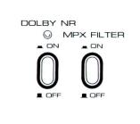
DOLBY NR SWITCH
Setting the Dolby NR Switch to ON position activates the Dolby circuit to raise low level Signals before they are recorded and lowers them by precisely the same amount during playback. This process eliminates extraneous and superimposed noise, thus also eliminating tape hiss.
*When using tape recorded with the Dolby processor it is necessary that this Switch be Set to ON position at playback also.
MPX FILTER SWITCH
Prevents disturbance caused by the 19 kHz pilot signal during FM stereo broadcast recording with
On utilise ces commandes pour regler le niveau d'entree lors d'un enregistrement par cäble. Le bouton interieur est pour le canal de gauche et Fanneau exterieur pour le canal de droite.
Il est facile d'augmenter et de reduire le son sur les deux canaux etant donne que les commandes sont coaxiales et tournent ensemble.
3t PRISES DE MICRO (Gauche/droite)
32 COMMUTATEURS DE MODE D'ENREGISTREMENT (Selecteurs de canaux gauche et droite) Appuyer sur le selecteur de droite ou de gauche pour un enregistrement monaural sur le Kanal de droite ou de gauche. Pour enregistrer en stereo, appuyer sur les deux commutateurs ä la fois.
* Attention: ne pas oublier de choisir les canaux avant d'enregistrer.
33 PRISE DE COMMANDE A DISTANCE
On peut comrpander ä distance toutes les fonctions de 1'appareil avec l'accessoire en option Unite de Commande ä distance RC-18, RC-70 T/R:
*On peut egalement realiser un enregistrement programme avec 1'unite de Commande ä distance et la minuterie. (Voir "enregistrement
programme ").
34 CORDON D'ALIMENTATION
35PRISES DE SORTIE DE LIGNE (Gauche/Droite) 36 PRISES D'ENTREE DE LIGNE (Gauche/Droite)
37 PRISE DIN (Certains modeles ne sont pas munis de cette prise)
Ce modele est muni d'une prise DIN qui permet de brancher facilement un amplificateur par 1'intermediaire d'un Beul cordon DIN. Cependant, pour eviter la diaphonie entre l'entree et la sortie DIN pendant 1'enregistrement, le signal de sortie DIN est coupe. Par consequent an ne peut pas contröler le son par l'intermediaire d'un amplificateur. Si 1'on veut contröler 1'enregistrement, utiliser la prise de casque de la platine magnetophone. La prise DIN ne fonctionnera pas si 1'on utilise la
COMMUTATEUR DE DOLBY NR
Le reglage du commutateur de Dolby NR sur ON a pour effet d'activer le circuit de Dolby et d'elever les signaux de faible niveau avant l'enregistrement et de les abaisser de la meme quantite lors de la reproduction. Ce procede a pour effet d'eliminer tout bruit etranger et surimpose, Aiminant par la meine tout sifflement de bande.
*Il est necessaire de maintenir ce commutateur sur la position ON lors de 1'utilisation d'une bande enregistree ä I'aide du processeur Dolby meme lors de la reproduction.
COMMUTATEUR DE FILTRE MPX (multiplex) Ce filtre empeche I'apparition de toute interferenc causee par le Signal pilote de 19 kHz lors de l'en
lichen, sind die linken und rechten Regler nicht nur koaxial hergestellt, sondern außerdem noch vom Reibungs-Typ, wodurch sie sich gemeinsam drehen.
31MIKROPHON-BUCHSE (links/rechts)
32AUFNAHMEFUNKTIONS-SCHALTER (linker und rechter Kanal-Wähler)
Drücke rechter oder linker Wähler für Mono-Auf- nahme, drücke beide Schalter gleichzeitig.
* Vorsicht: Wählen Sie die Kanäle vor der Aufnahme.
33 FERNBEDIENUNGS-BUCHSE
Fernbedienung aller Betriebs-Funktionen wird mit der wahlweise zur Verfügung stehenden FernbedienungsEinheit RC-18, RC-70 T/R ermöglicht.
*Aufnahme in Abwesenheit wird ermöglicht bei Anwendung der Fernbedienungs-Einheit zusam-
men mit einem Zeitschalter. (Siehe AUFNAHMEFUNKTION IN ABWESENHEIT).
34NETZKABEL
35LINE-AUSGANGS-BUCHSE (rechts/links)
36LINE-EINGANGS-BUCHSE (rechts/links)
37DEN-BUCHSE (Einige Modelle haben diese
Anlage nicht)
Dieses Modell wurde mit einer DEN-Buchse ausgerüstet, um eine Verbindung mit einem Verstärker durch ein einziges DEN-Kabel zu ermöglichen: Jedoch, um eine Kreuzkopplung zwischen DENEingang und Ausgang während der Aufnahme auszuschließen, ist das DEN Ausgangs-Signal unterbrochen. Eine Mithör-Kontrolle durch den Lautsprecher ist daher nicht möglich. Wird eine MithörKontrolle während der Aufnahme gewünscht, so kann die Kopfhörer-Buchse am Deck verwendet werden. Bei Benützung der Mikrophon-Buchse funktioniert die DEN-Buchse nicht, richten Sie die Aufnahme-Eingabe nach der Mikrophon-Eingabe- Kontrolle.
LÄRMBEWERTUNGS-DOLBY-NR-SCHALTER
Wenn Sie den Dolby-NR-Schalter auf ON (Ein) schalten, tritt der Dolby-Stromkreis in Funktion, wodurch schwache Signale vor der Aufnahme verstärkt und bei der Wiedergabe im gleichen Maße wieder abgeschwächt werden. Durch diesen Vorgang werden Fremdund Überlagerungsgeräusche ausgeschaltet, wodurch auch das Bandrauschen verschwindet.
*Wenn Sie ein Band benutzen, das mit Hilfe der Dolby-Vorrichtung bespielt wurde, müssen Sie diesen Schalter auch bei der Wiedergabe auf ON schalten.
MPX (MEHRFACH)-FILTER-SCHALTER
Hiermit werden die Störungen ausgeschaltet, die bei der Aufnahme von UKW-Stereosendungen über ein
Downloaded from www.Manualslib.com manuals search engine
the Dolby System through an FM receiver or uuner. * "Dolby" and the Double D symbol are trademarks of Dolby Laboratories. (Manufactured under license from Dolby Laboratories).
registrement d'une radioemission stereophoniq FM avec le systeme Dolby dans le recepteur FM ou le uuner.
*"Dolby" et le symbole du double D sont des marques deposees de Dolby Laboratories. (Manu-
facture sous license de Dolby Laboratories.)
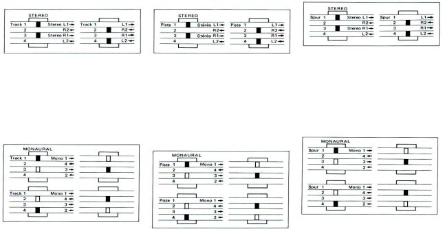
4-TRACK STEREO RECORDING AND |
SYSTEME DE REPRODUCTION ET |
4-SPUR-STEREO-AUFNAHME/WIEDERGABE |
PLAYBACK SYSTEM |
D'ENREGISTREMENT STEREO 4 PISTES |
|
Stereo recording requires the simultaneous use of two tracks. For stereo operation, depress both Recording Mode Switches. The first stereo recording takes place an tracks 1 and 3, and the second an tracks 2 and 4 after the Reverse Button has been depressed in the Recording Mode. The first stereo playback takes place an tracks 1 and 3, and the second an tracks 2 and 4 after the Reverse Button has been depressed in the Playback Mode.
4-TRACK MONAURAL RECORDING AND PLAYBACK SYSTEM
4-track monaural recording sequence is l-4-3-2. For monaural operation, depress the left Recording Mode Switch. The first recording takes place an track 1 and second an track 4 after the Reverse Button has been depressed in the Recording Mode. For recording an Tracks 3 and 2, depress the right Recording Mode Switch. The third recording takes place an track 3, and the fourth an track 2 after the Reverse Button has been depressed in the Recording Mode.
11 faut utiliser deux pistes ä la fois lorsqu'on veut enregistrer en stereo. Pour obtenir la stereo, appuyer en mime temps sur les touches d'enregistrement. Le premier enregistrement stereo s'effectue sur les pistes 1 et 3 et le second sur les pistes 2 et 4 apres que 1'on ait enfonce le bouton de retour sur le mode "enregistrement". La premiere reproduction stereo est effectuee sur les pistes 1 et 3, et la deuxieme sur les pistes 2 et 4 apres avoir appuye sur le bouton d'inversion dans le mode de reproduction.
SYSTEME DE REPRODUCTION ET D'ENREGISTREMENT MONAURAL 4 PISTES
L'ordre d'enregistrement en monaural 4 pistes est l-4-3-2. Pour obtenir le mono, appuyer sur la touche d'enregistrement de gauche. Le premier enregistrement s'effectue sur la piste 1 et le second sur la piste 4 apres que 1'on ait enfonce la touche de retour sur le mode "enregistrement". Pour enregistrer sur les pistes 3 et 2, appuyer sur la touche d'enregistrement de droite. Le troisieme enregistrement se trouvera sur la piste 3 et le quatrieme sur la piste 2 apres que 1'on ait enfonce la touche de retour sur le mode "enregistrement".
Stereo-Aufnahme benötigt die gleichzeitige Anwendung von zwei Spuren. Für Stereo-Funktion müssen beide Aufnahme-Stellungs-Schalter gedrückt werden. Die erste Stereo-Aufnahme erfolgt auf Spuren 1 und 3, und die zweite auf Spuren 2 und 4, nachdem die RücklaufTaste in Aufnahme-Stellung gedrückt wurde. Die erste StereoWiedergabe erfolgt auf Spule 1 und 3, und die zweite auf 2 und 4, nachdem die Rücklauf-Taste in WiedergabeStellung gedrückt wurde.
4-SPUR-MONO-AUFNAHME/WIEDERGABE
Die Aufnahmen-Reihenfolge bei 4-Spul-Mono-Auf- nahme ist l-4-3-2. Für Mono-Funktion muß der linke Aufnahme-Stellungs-Schalter gedrückt werden. Die erste Aufnahme erfolgt auf Spule 1 und die zweite auf Spule 4, nachdem die Rücklauf-Taste in Aufnahme-Stel- lung gedrückt wird. Für Aufnahme auf Spule 3 und 2 muß der rechte Aufnahme-Stellungs-Schalter gedrückt werden. Die 3. Aufnahme erfolgt auf Spule 3 und die 4. auf Spule 2 nachdem die Rücklauf-Taste in AufnahmeStellung gedrückt wurde.
Downloaded from www.Manualslib.com manuals search engine
TAPE LOADING
l.Place a full reel of tape an the supply reel table and an empty reel of the same size an the take-up reel table.
2.Lock both reels into place by pulling tip of reel retainers outward and turning to left or right.
3.Lock tension arms to extreme outside positions.
4.Unwind about an 85 cm length of tape from the supply reel and thread the tape as shown by the dotted lines in the figure.
5.Insert end of tape in slot of empty reel and wind around reel hub two or three times.
6.Continue winding tape onto take-up reel until all slack has been taken up.
7.Release tension arms inward to stand by position
when loading has been completed.
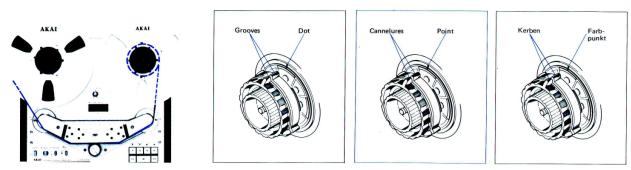
When using 10-l/2" reels, place the Standard accessory reel adapter hubs an the left and right reel tables and lock into place by pulling tip of reel retainers outward and turning to left or right.
When using 10-1/2" plastic reels
Fit hubs over reel tables so that the grooves an the inner and outer adapter hubs are aligned and match these lines with the dot an reel table.
When using 10-1/2" metallic reels
Fit hubs over reel tables so that the grooves an the inner and outer adapter hubs are aligned, but do not match with dot an reel table. (This provides the necessary spacing for the difference in plastic and metal reel thickness).
CHARGEMENT DE LA BANDE
I. Placer une bobine pleine sur le plateau de bobine debitrice et une bobine vide de meme taille sur le plateau de bobine receptrice.
2.Fixer les deux bobines en tirant vers 1'exterieur 1'extremite du fixe-bobine et en le faisant tourner ensuite vers la droite ou vers la gauche.
3.Bloquer les bras de tension sur les positions exterieures.
4.Derouler ä peu pres 85 cm de bande ä partir de la bobine debitrice et engager la bande comme indique en pointille sur la figure.
5.Introduire 1'extremite de la bande dans la fente de la bobine vide et enrouler deux ou trois fois la bande
autour de faxe de la bobine.
6.Continuer ä enrouler la bande autour de la bobine receptrice jusqu'ä ce qu'elle soit bien tendue.
7.Laisser revenir les bras de tension vers 1'interieur Sur la position d'attente une fois les bobines mises en place.
Lorsque 1'on utilise des bobines de 27 cm, les placer sur les plateaux gauche et droit et les bloquer ä 1'aide de 1'extremite du fixe-bobine que 1'on tire vers 1'exterieur avant de le faire tourner vers la gauche ou la droite. Lorsque Von utilise des bobines en plastique de 27 cm Fixer les centreurs sur les plateaux de bobines de maniere ä ce que les cannelures des centreurs interieurs et exterieurs soient parfaitement alignees avec les lignes en pointille sur les plateaux de bobines.
Lorsque 1'on utilise des bobines metalliques de 27 cm Fixer les centreurs Sur les plateaux de bobines de maniere ä ce que les cannelures des centreurs interieurs
BANDEINLAGE
l.Legen Sie eine volle Bandspule auf den VersorgungsHalter und eine leere Spule auf den AufnahmeHalter.
2.Beide Spulen in ihrer Position einrasten, indem sie die Spitze der Spulenhalter nach außen ziehen und dann nach links oder rechts drehen.
3.Die Spannungsarme in den äußersten Außenposi-
tionen einrasten.
4.Wicklen Sie ungefähr 85 cm Bandlänge vom Ver- sorgungs-Halter ab und führen Sie das Band ein gemäß der punktierten Linie in der Darstellung.
5.Führen Sie das Bandende in den Schlitz des leeren Halters ein und wickeln Sie es zwei bis drei Mal um den Spulenkern.
6.Wickeln Sie das loose Band um den Spulenkern bis
es aufgebraucht ist.
7.Bringen Sie die Spannungsarme wieder in BetriebsStellung, wenn die Bandeinlage ausgeführt ist.
Bei Anwendung einer 27 cm Spule legen Sie die im Standardzubehör enthaltenen Adapter-Kerbe auf den linken und rechten Spulenteller und rasten sie es ein, indem Sie die Spitze der Spulenhalter nach außen ziehen und dann nach links oder rechts drehen.
Bei Anwendung einer 27 cm Plastik-Spule
Plazieren Sie die Kerbe über Spulenteller, so daß die Kerben auf den inneren und außeren Adapter-Kerben auf der gleichen Höhe sind und mit den Punkten auf dem Spulenteller übereinstimmen.
Bei Anwendung einer 27 cm Metall-Spule
Plazieren Sie die Kerbe über Spulenteller, so daß die Kerben auf den inneren und äußeren Adapter-
Downloaded from www.Manualslib.com manuals search engine
GENERAL PRECAUTIONS IN TAPE HANDLING
AKAI LN-150-7 or SCOTCH #211 Low Noise Tape is considered standard for this machine. The use of regular tape is not recommended.
Set to Wide Range position only when using special wide range tape of a grade higher than low noise tape. As tapes which have not been used for a period of time may have become sticky, run tape once before using.
Always store tapes in a cool, dry place. Finger marks an the tape will cause drop out. No recording can be made an the leader tapes at both ends (first part and end of reel) of the tape. Thus, before starting, take up the leader tape.
Full care must be taken in tape handling when using thin tape (200% and above: e.g., when tape of a 740m length (2,400 ft) is used with Small Hub 7 Inch Reel). Long-period storage of tapes that was taken up in a fast-forward or rewind mode will cause damage to the tape, leading to unexpected troubles or will make them unfit for use.
Therefore, the tapes should be stored in a condition as taken up in an orderly manner, with the tape traveling at the fixed speed of Recording or Playback. However, either rewind or fast-forward the entire of tape before use of the tape after storage.
et exterieurs soient parfaitement alignees avec les lignes |
Kerben auf der gleichen Höhe sind, aber nicht mit den |
en pointille sur les plateaux de bobines. (Cela permet de |
Punkten auf dem Spulenteller übereinstimmen. (Dies |
compenser la differente d'epaisseur entre les bobines en |
ergibt den nötigen Abstand für den Unterschied von |
metal et en plastique). |
Plastikund Metall-Spulen-Dicke). |
PRECAUTIONS A PRENDRE LORSQU'ON MANIPULE LES BANDES
Les bandes Low Noise AKAI LN-150-7 et SCOTCH #211 sont celles qui conviennent le mieux avec cet appareil. Il n'est pas recommande d'utiliser des bandes normales.
Ne placer sur la position Wide Range que si l'on utilise des bandes Wide Range de qualite superieure aux bandes Low Noise.
Les bandes qui n'ont pas ete utilisees depuis longtemps peuvent devenir collantes, les faire defiler une fois avant de les utiliser.
Toujours remiser les bandes dans un endroit frais et sec.
Les marques de doigt sur la bande provoqueront une chute de son.
Ort ne peut effectuer aucun enregistrement en debut ou en fin de bande (depart et fin de la bobine). Par consequent, avant de commencer, enrouler une partie de la bande sur la bobine receptrice.
II faut faire très attention lorsqu'on manipule une bande de faible epaisseur (200% et plus: par exemple lorsque l'on utilise une bande de 740m de long (2400 ft) avec un centreur de bobine 18 cm. Si l'on remise pendant longtemps des bandes qui ont éte enroulees en avance rapide ou en rebobinage, il se peut que la bande soit abimee et qu'elle provoque des ennuis inattendus ou meme qu'elle ne puisse plus etre utilisée.
Par consequent, les bandes devront etre enroulees ä la vitesse d'enregistrement ou de reproduction avant d'etre rangees. Cependant, avant de réutiliser la bande après l'avoir rangée, il faut la faire defiler entièrement en avance rapide ou en rebobinage.
ALLGEMEINE VORSICHTS-MASSNAHMEN BEI DER BANDBEDIENUNG
Es sollten nur AKAI LN-150-7 oder SCOTCH #211 geräuscharme Bänder auf diesem Gerät abgespielt werden. Gewöhnliche Bänder werden nicht empfohlen. Schalten Sie nur auf die Weitbereich-Stellung um, wenn Sie ein spezielles Weitbereich-Band verwenden, ein Grad höher als das geräuscharme Band. Bänder, die über längere Zeit nicht gebraucht wurden, können zusammenkleben, spulen Sie sie einmal durch, bevor Sie sie benützen.
Lagern Sie Tonbänder immer an einem kühlen trockenen Platz.
Fingerabdrücke auf dem Band verursachen Tonausfälle.
Zu beiden Enden des Führungsbandes ist keine Aufnahme möglich (Anfang und Ende der Spule). Spulen Sie vor der Aufnahme zuerst das Führungsband auf.
Besonders vorsichtig müssen dünne Bänder angewendet werden (200% und darüber, z.B. Bänder von 740m Länge (2400 Fuß) mit Klein-Kern 7 Inch Spule).
Langfristige Lagerung von Bändern, die im Schnell- Vorwärts-oder Rückspul-Vorgang aufgewickelt wurden, schadet dem Band und führt zu unerwarteten Störungen oder macht eine Benützung des Bandes unmöglich. Die Bänder sollten daher aufbewart werden, nachdem sie mit normaler Bandgeschwindigkeit in der Aufnahmeoder Wiedergabe-Position abgewickelt wurden. Spulen Sie auf keinen Fall ein gelagertes in der Rückspuloder Schnell- Vorwärts-Position ab.
DIRECT FUNCTION CHANCE CONTROL
This model features feather-touch Full Direct Function Change Control. The necessity of depressing the Stop Button prior to changing modes is eliminated. The inclusion of direkt function change to recording mode facilitates easy add-on recording.
COMMANDE A CHANGEMENT DE FONCTION DIREKTE
Ce systbme est 6quip6 d'un systeme de commande ä effleurement ä changement de fonction direkte. II n'est pas n6cessaire d'enfoncer le bouton d'arret avant de changer de mode de fonctionnement. La possibilit6 de passer directement sur le mode d'enregistrement facilite les montages.
DIREKTE FUNKTIONSWAHL AUS JEDER LAUFFUNKTION
Dieses Gerät ist für direkte Umschaltung von einer Lauffunktion in eine andere mittels der empfindlichen Drucktasten ausgelegt. Es ist daher nicht erforderlich, vor Wahl einer anderen Funktion die Stoptaste zu betätigen. Da Sie auch auf Aufnahme jederzeit direkt umschalten können, kommen Einsätze genau an die gewünschte Stelle.
Downloaded from www.Manualslib.com manuals search engine
 Loading...