

Page 1
W"
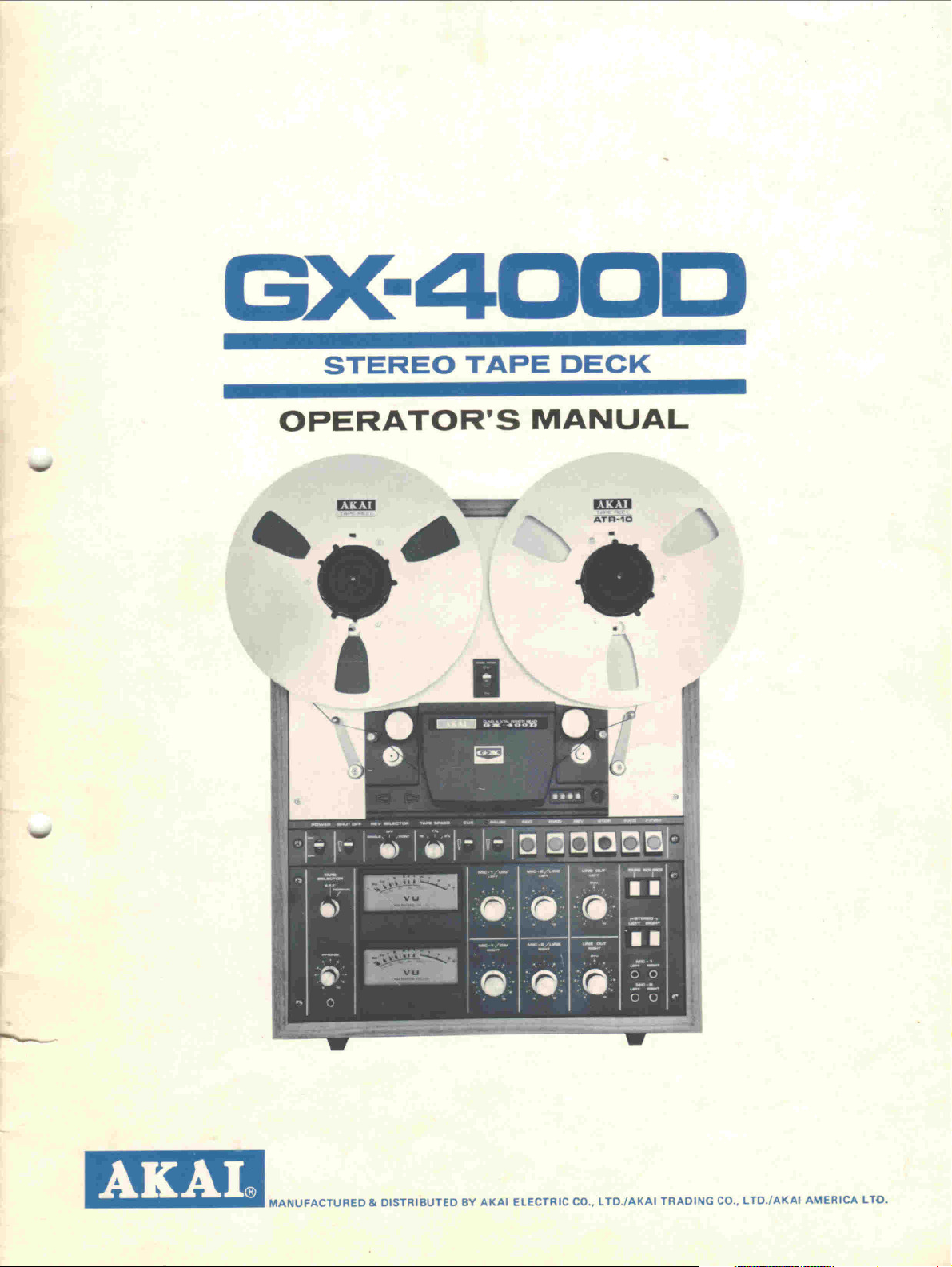
GX-4DDD
STEREO TAPE DECK
OPERATOR' S MANUAL
IDJ] ~ Dm
,:~
~
.'.
-=:.7
'"
T~T~a
"
i I ,
~-
'I
~
-----
.
1mB
GI
MANUFACTURED& DISTRIBUTEDBY AKAI ELECTRICCD., LTD./AKAI TRADINGCO., LTD./AKAI AMERICALTO.
Page 2
mn
~. ~ .
--
~
.
i I
.
f
......
.."...".
ALL GX (glass & single crystal ferrite) HEADS
Akai has equipped this model wfth its new and amazing GX
Heads to bring you unequalled open reel high fidelity
sound. With the symmetrical head block lay-out and dual
capstan drive system of this model, an undistorted wide
frequency response range covering 30,000 Hz für com-
pletely professional performance. With the GX Heads, a
wider dynamie range and excellent signal-to-noise ratio are
also attained. These accomplishments are contributable to
head materials, superior processing technique, and a
"focused-field" recording system. The core of these extra-
ordinary heads are made of single crystal ferrite and are
mounted and set in glass. This focused-field recording
system minimizes high frequency lass and eliminates undue
equalization für perfect recording results.
A.D.R SYSTEM
The GX-400D incorporates Akai's new and unique Auto-
matie Distortion Reduction circuit. This circuit prevents
interference and beat noise from occuring during high input
recording. At input signals over 8,000 Hz where tape is
easily saturated, the selective network of the A.D.R circuit
is automatically activated to change the recording equali-
zation according to input. The result is clear and dis-
tortionless high range playback over an extended frequency
range.
...
..".;
Page 3
w
INDEX
Controls 2
PIease read the following
precau tions before operation. . . . . . . . . . . . . . . . . . . 4
Howtoload amagnetic tape 4
4-Track stereo recording and
playback system 5
4-Track monaural recording and
playback system 5
Automatic and manual reverse
recordingandplayback , 5
Tapeselectorswitch 6
w
r
Tapespeedselection 6
Direct function change control system. . . . . . . . . . . .. 6
Cueswitch 6
Automaticstopandshut-off
Pausecontrol 6
Remotecontrol 6
Connectionsforplayback 7
Playback 8
Connectionsforrecording 9
Recording 10
Echo effect IO
Sound-on-soundrecording 111
Soundmixing 11
Tapeerasing 11
Tape splicing andediting 11
Heads should always be kept clean. . . . . . . . . . . . . . . 212
Pinch wlieel and capstan cleaning 212
Headdemagnetizing 12
Voltage and cycle conversion . . . . . . . . . . . . . . . . . . . . 1313
Technicaldata 14
Standardaccessories 14
Troubleshootingchart 15
,
6
[I]
Page 4
'!
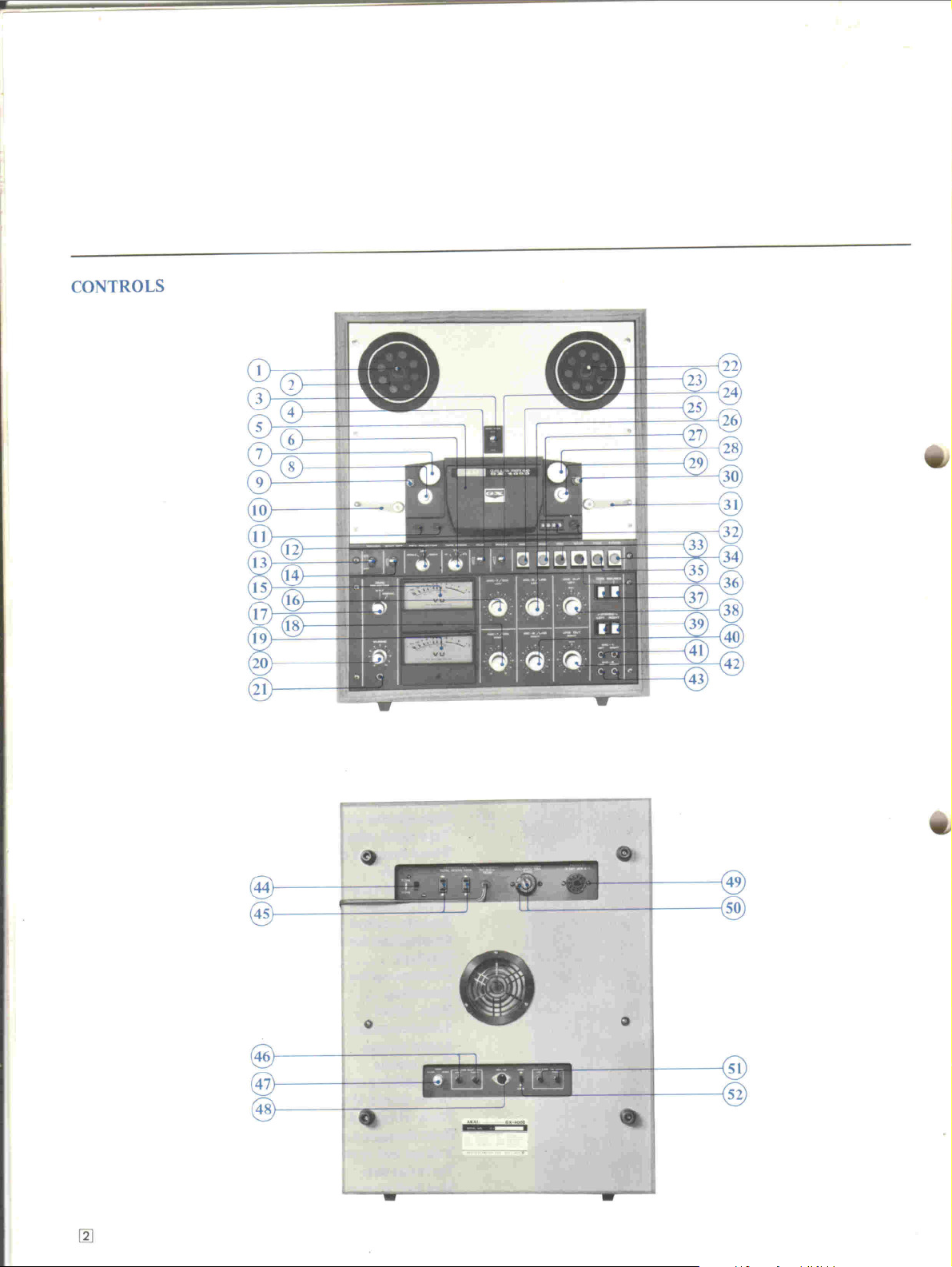
CONTROLS
t
,t'
.,
[1J
0
G
.
-
E!]]E!]ö =0
=:i
.,
e
~
..
Page 5
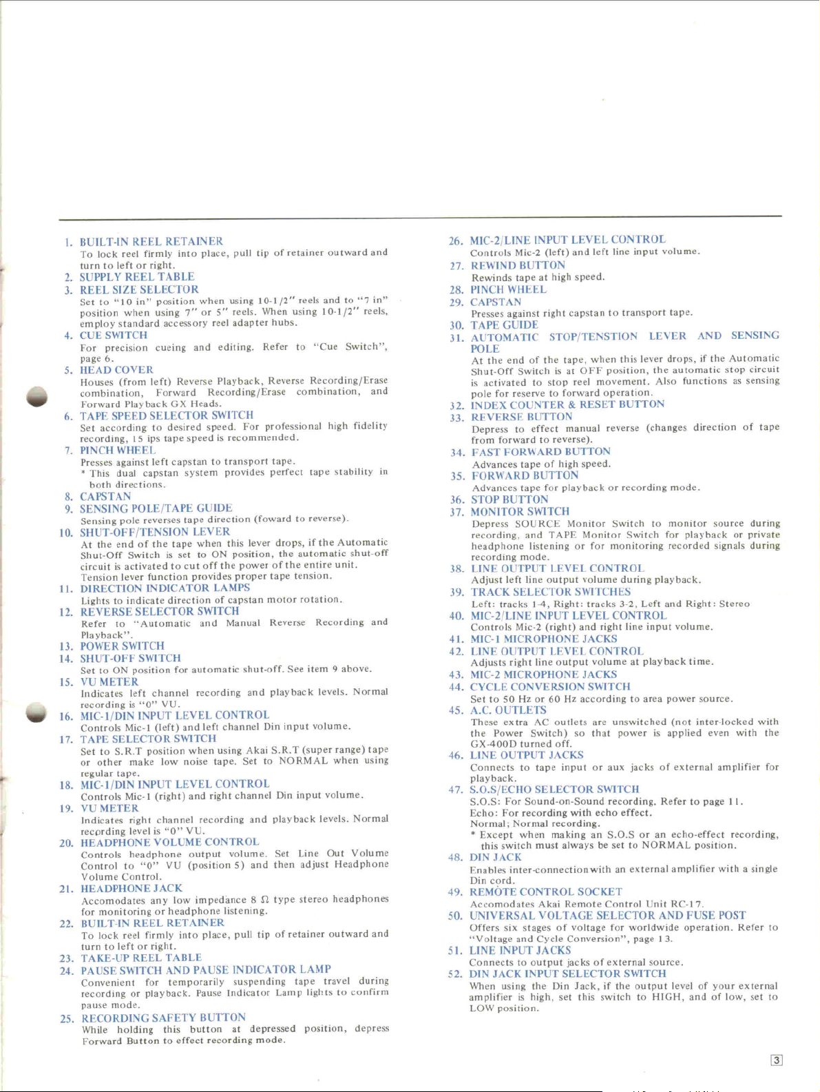
I. BUlLT-IN REEL RETAINER
To lock reel firmly into place, pull tip of retainer outward and
turn to left or fight.
2. SUPPLY REEL TABLE
3. REEL SIZE SELECTOR
Set to "10 in"
position when using
employ standard accessory reel adapter hubs.
4. CUE SWITCH
For precision cueing and editing. Refer to "Cue Switch",
page 6.
5. HEAD COVER
Houses (from left) Reverse Playback, Reverse Recording/Erase
.
.,
~
combination, Forward Recording/Erase combination, and
Forward Playback GX Heads.
6. TAPE SPEED SELECTOR SWITCH
Set according to desired speed. For professional high fidelity
recording, 15 ips tape speed is recommended.
7. PINCH WHEEL
Presses against left capstan to transport tape.
.
This dual capstan system provides perfect tape stability in
both directions.
8. CAPSTAN
9. SENSING POLE/TAPE GOlDE
Sensing pole reverses tape direction (foward to reverse).
10. SHUT-OFF/TENSION LEVER
At the end of the tape when this lever drops, if tl1e Automatie
Shut-Off Switch is set to ON position, the automatic shut-off
circuit is activated to cut off the power of the entire unit.
Tension lever function provides proper tape tension.
11. DlRECTlON INDICATOR LAMPS
Lights to indieate direction of capstan motor rotation.
12. REVERSE SELECTOR SWITCH
Refer to "Automatie and Manual Reverse Recording and
Playback".
13. POWER SWITCH
14. SHUT-OFF SWITCH
Set to ON position for automatie shut-off. See item 9 above.
15. VU METER
Indieates left channel recording and playback levels. Normal
recording is
16. MIC-l/DIN INPUT LEVEL CONTROL
Controls Mic-l (left) and left channel Din input volume.
17. TAPESELECTORSWITCH
Set to S.R.T position when using Akai S.R.T (super range) tape
or other make low noise tape. Set to NORMAL when using
regular tape.
18. MIC-l/DIN INPUT LEVEL CONTROL
Controls Mic-l (right) and fight channel Din input volume.
19. VU METER
Indicates fight channel recording and playback levels. Normal
recprding level is
20. HEADPHONE VOLUME CONTROL
Controls headphone output volume. Set Line Out Volume
Control to
Volume Control.
21. HEADPHONEJACK
Accomodates any low impedimce 8 n type stereo headphones
for monitoring or headphone listening.
22. BUlLT-IN REEL RETAINER
To lock reel firmly into place, puB tip of retainer outward and
turn to left or fight.
23. T AKE-UP REEL T ABLE
24. PAUSE SWITCH AND PAUSE INDICATOR LAMP
Convenient for temporarily suspending tape travel during
recording or playback. Pause Indieator Lamp lights to confirm
pause mode.
25. RECORDING SAFETY BUTTON
While holding this button at depressed position, depress
Forward Button to effect recording mode.
position when using 10-1/2" reels and to
7" or 5"
VU.
"0"
VU.
"0"
VU (position 5) and then adjust Headphone
"0"
reels. When using 10-1/2" reels,
"7 in"
26. MIC-2/UNE INPUT LEVEL CONTROt
Controls Mic-2 (Ieft) and left liDe input volume.
27. REWIND BUTION
Rewinds tape at high speed.
28. PINCH WHEEL
29. CAPSTAN
Presses against fight capstan to transport tape.
30. TAPE GUIDE
31. AUTOMA TlC STOP/TENSTION LEVER AND SENSING
POLE
At the end of the tape, when this lever drops, if the Automatic
Shut-Off Switch is at OFF position, the automatic stop circuit
is activated to stop reet movement. Also functions as sensing
pole for reserve to forward operation.
32. INDEX COUNTER & RESET BUTION
33. REVERSE BUTTON
Depress to effect manual reverse (changes direction of tape
from forward to reverse).
34. FAST FORWARD BUTTON
Advances tape of high speed.
35. FORWARD BUTTON
Advances tape for playback or recording mode.
36. STOP BUTION
37. MONITOR SWITCH
Depress SOURCE Monitor Switch to monitor source during
recording, and TAPE Monitor Switch for playback or private
headphone listening or for monitoring recorded signals during
recording mode.
38. UNE OUTPUT LEVEL CONTROL
Adjust left liDe output volume du ring playback.
39. TRACK SELECTOR SWITCHES
Left: tracks 1-4, Right: tracks 3-2, Left and Right: Stereo
40. MIC-2/UNE INPUT LEVEL CONTROL
Controls Mic-2 (right) and fight line input volume.
41. MIC-l MICROPHONE JACKS
42. UNE OUTPUT LEVEL CONTROL
Adjusts fight liDe output volume at playback time.
43. MIC-2 MICROPHONE JACKS
44. CYCLE CONVERSION SWITCH
Set to SO Hz or 60 Hz according to area power source.
45. A.c. OUTLETS
These extra AC outlets are unswitched (not inter-locked with
the Power Switch) so thaI power is applied even with the
GX-400D turned off.
46. UNE OUTPUT JACKS
Connects to tape input or aux jacks of external amplifier for
pla yback.
47. S.O.S/ECHO SELECTOR SWITCH
S.O.S: For Sound-on-Sound recording. Refer to page 11.
Echo: For recording with echo effect.
Normal; Normal recording.
.
Except when rnaking an S.O.S or an echo-effect recording,
this switch must always be set to NORMAL position.
48. DlN JACK
Enables inter-connectionwith an external amplifier with a single
Din cord.
49. RE MO TE CONTROL SOCKET
Accomodates Akai Remote Control Unit RC-I 7.
SO. UNIVERSAL VOLTAGE SELECTOR AND FUSE POST
Offers six stages of voltage for worldwide operation. Refer to
"Voltage and Cycle Conversion", page 13.
5 I. UNE INPUT JACKS
Connects to output jacks of external source.
52. DlN JACK INPUT SELECTOR SWITCH
When using the Din lack, if the output level of your external
amplifier is high, set this switch to HIGH, and of low, set to
LOW position.
rn
Page 6
PLEASE READ TUE FOLLOWING PRECAUTIONS BEFORE OPERATION
* Your machine requires constan t voltage fOT optimum
performance. Pie ase feier to voltage and cycle con- * Avoid using extremely thin tape whenever possible.
version procedure on page 13 if change of voltage or When the use of such tape is unavoidable, be sure to
cycles is necessary. depress the Stop Button before changing modes.
* As dirty heads and magnetized heads become the
source of logs of sound, distortion, sound drop-out, may have become sticky, run tape once before using.
and other recording and playback failures, the heads
most be kept clean and demagnetized at all times.
* Place machine on a flat level surface. Operate in either
vertical or horizontal position.
Do not place anything on top of the unit which will
*
obstruct the ventilator.
If the sound sources are so rar away from the
*
microphones that the input level controls most be
tumed to maximum, some hum or noise will inevitably
be recorded.
A test recording is recommended before making a final
recording.
.
....
\
'i~-"'.
.
'~I
I" I
I
~ I
/
Use good quality tape. New tape gives best results.
*
As tapes which have not been used fOTaperiod of time
*
Always store tapes in a cool, dry place.
*
Should there be a problem with your machine, write down
the model and serial numbers and all pertinent data
regarding warranty coverage as weIl as a clear description of
the existing trouble and contact your nearest authorized
Akai Service Station or the Service Department of Akai
Company, Tokyo, Japan.
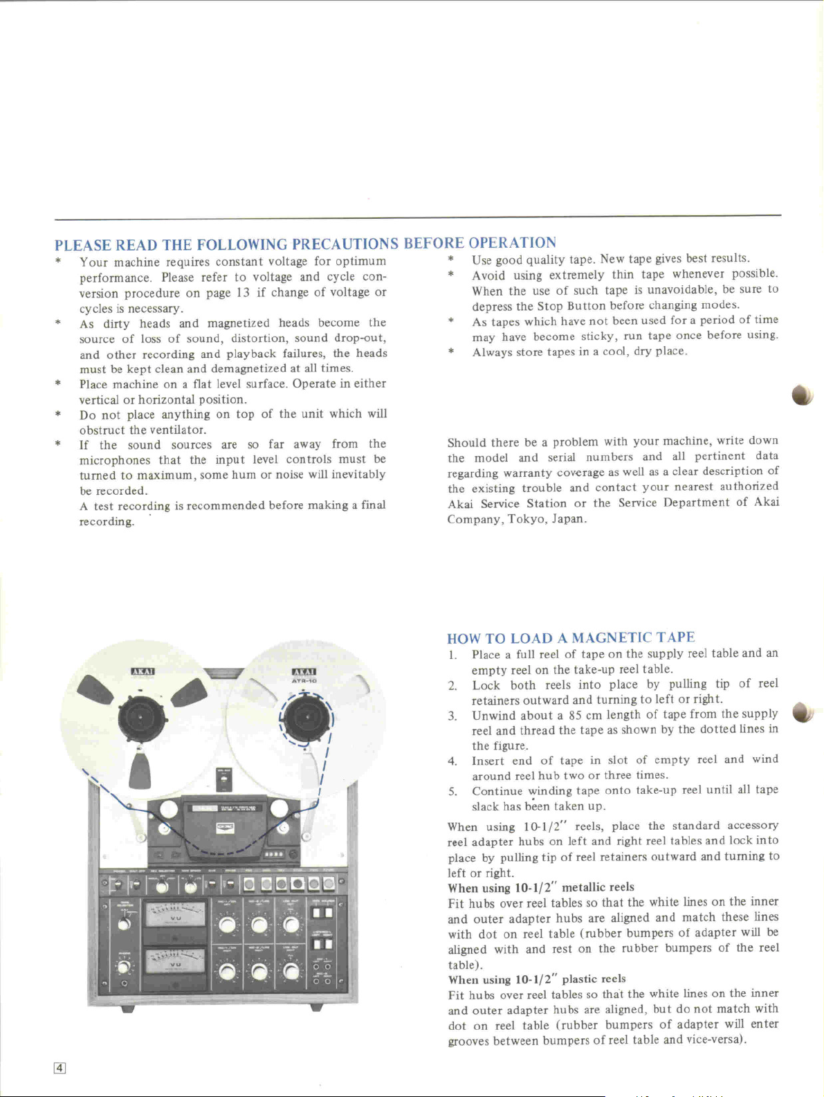
UOW TO LOAD A MAGNETIC TAPE
I. PIace a full reel of tape on the supply reel table and an
empty reel on the take-np reel table.
2. Lock both reels into place by pulling tip of re el
retainers out ward and tuming to left or fight.
3. Unwind about a 85 cm length of tape from the supply
reel and thread the tape as shown by the dotted lines in
the figure.
4. Insert end of tape in slot of empty reel and wind
around reel hu b two or three times.
5. Continue winding tape onto take-np reel until all tape
slack hag been taken up.
When using 10-1/2" reels, place the standard accessory
reel adapter hubs on left and fight reel tables and lock into
place by pulling tip of reel retainers outward and tuming to
left or fight.
When using 10-1/2" metallic reels
Fit hubs over reel tables so that the white lIDes on the inner
and outer adapter hubs are aligned and match these lines
with dot on reel table (rubber bumpers of adapter will be
aligned with and rest on the rubber bumpers of the re el
table).
When using 10-1/2" plastic reels
Fit hubs over reel tables so that the white lines on the inner
and outer adapter hubs are aligned, hut do not match with
dot on reel table (rubber bumpers of adapter will enter
grooves between bumpers of reel table and vice-versa).
..
-
~
Page 7
Track1
2
3
4
STEREO
I I
. StereoL1-
. StereoR1-
R2-
L2-
Track 1
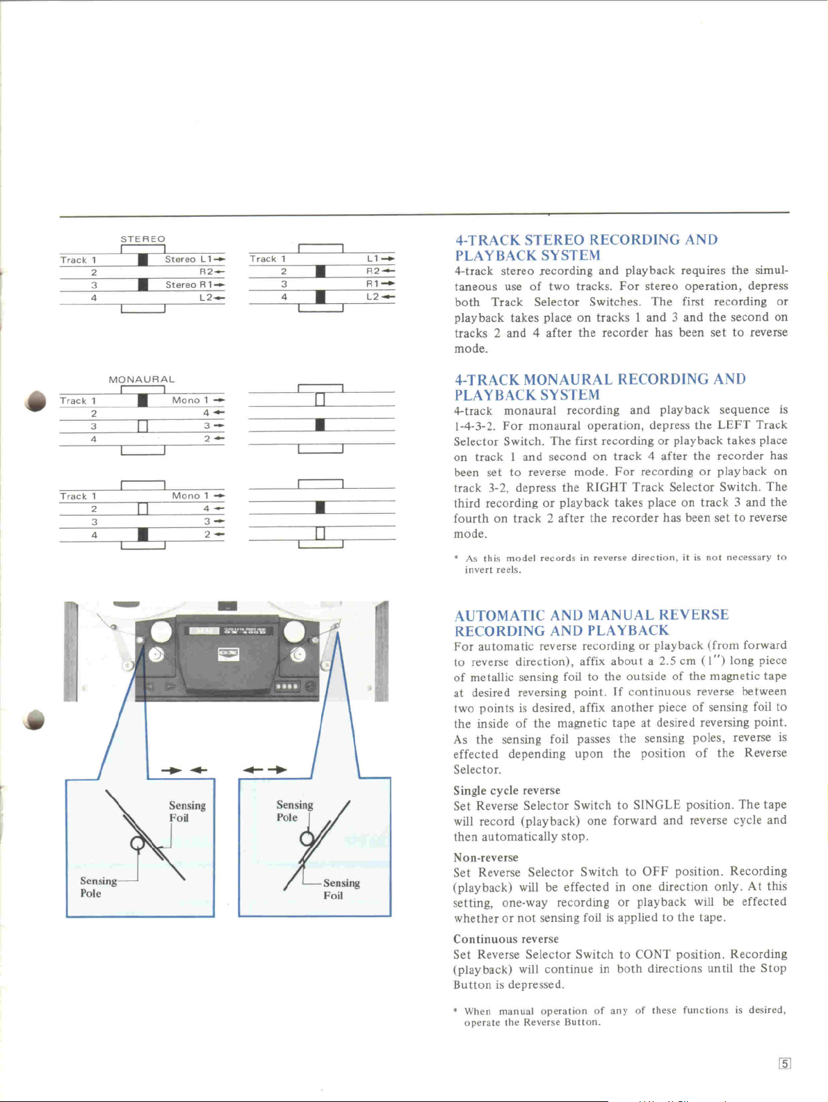
4-TRACK STEREO RECORDING AND
2
.
3
4
.
L1-
R2-
R1-
L2--
PLAYBACK SYSTEM
4-track stereo eecording and playback requires the sirnul-
taneous use of two tracks. For stereo operation, depress
both Track Selector Switches. The first recording or
playback takes place on tracks 1 and 3 and the second on
tracks 2 and 4 after the recorder has been set to reverse
mode.
.
.
Track 1
Track 1
MONAURAL
I
2
3
4
2
3
4
-
~
.
11
11
.
I
Mono 1 -
Mono1-
~
4-
3-
2--
4-
3-
2-
-
.- ....
n
.
.
[I
4-TRACK MONAURAL RECORDING AND
PLA YBACK SYSTEM
4-track monaural recording and playback sequence is
1-4-3-2. For monaural operation, depress the LEFT Track
Selector Switch. The first recording or playback takes place
on track 1 and second on track 4 after the recorder has
been set to reverse mode. For recording or playback on
track 3-2, depress the RIGHT Track Selector Switch. The
third recording or playback takes place on track 3 and the
fourth on track 2 after the recorder has been set to reverse
mode.
.
As this model records in reverse direction, it is not necessary to
invert reels.
AUTOMA TIC AND MANUAL REVERSE
RECORDING AND PLAYBACK
For automatie reverse recording or playback (from forward
to reverse direction), affix about a 2.5 cm (1") long piece
of metallic sensing foi! to the outside of the magnetic tape
at desired reversing point. If continuous reverse between
two points is desired, affix another piece of sensing foil to
the inside of the magnetic tape at desired reversing point.
As the sensing foil passes the sensing poles, reverse is
effected depending upon the position of the Reverse
Selector.
Single cycle reverse
Set Reverse Selector Switch to SINGLE position. The tape
will record (playback) Olle forward and reverse cyc1e and
then automatically stop.
Non-reverse
Set Reverse Selector Switch to OFF position. Recording
(playback) will be effected in Olle direction only. At this
setting, one-way recording or playback will be effected
whether or not sensing foi! is applied to the tape.
Continuous reverse
Set Reverse Selector Switch to CaNT position. Recording
(playback) will continue in both directions until the Stop
Button is depressed.
.When manual operation of any of these functions is desired,
operate the Reverse Button.
[ID
Page 8

.....
TAPE SELECTOR SWITCH
This model is equipped with a Tape Selector Switch. Use of
this switch brings out the maximum response of high
performance low noise tapes and works to change the
recording equalization according to the tape. The combi-
nation of Akai GX Heads and low noise tape hag enabled
startling progress in tone quality.
.
When low noise tape is not being used, this switch must be set to
NORMAL position.
TAPE SPEED SELECTION
This model can be operated at 15, 7-1/2, or 3-3/4 ips tape
speed. Simply depress Tape Speed Selector Switch accord-
ing to desired speed. Recording time with an 1,800 ft. tape
is as follows: (stereo) 3 hrs at 3-3/4 ips; 1.5 hrs. at
7-1/2 ips: 45 min. at 15 ips.
.
For professional recording, 15 ips tape speed is recommended.
DIRECT FUNCTION CHANGE CONTROL
SYSTEM
This model employs a direct function change contral
system foT speedy mode selection. The necessity of
depressing the Stop Button before changing modes is
eliminated. Further the controls are equipped with in-
dividual colored lights which indicate each operating mode.
.
The use of extremely thin tape should be avoided. When the use
of such tape is absolutely necessary, it is recommended thaI the
Stop Button be depressed before changing operating mo des.
PAUSE CONTROL
This model is equipped with a Pause Switch foT momen-
tarily stopping tape travel du ring recording or playback.
This feature is especially convenient foT editing tapes.
Simply set Pause Switch in direction of the arrow when
a certain portion of the program is not desired. Note that
the Pause lndicator Lamp will light to confirm pause mode.
Return Pause Switch to normai position to resurne record-
ing.
REMOTE CONTROL
All operating functions of this model can be remote
controlled by using Akai Remote Contral unit RC-17
optional accessory. Plugs into Remote Contral Socket on
rear panel.
~
CUE SWITCH
The Cue Switch facilitates precision cueing and editing.
When the switch is set to ON position during fast forward
or rewind, a "tweeting" sound can be heard where there are
recordings on the tape. Where there are no recordings, or at
the blank space between recordings, no sound is audible.
After stopping tape at desired position, move reels while
listening to the sound, so thai the correct location is
obtained.
.
When using the Cue Switch the TAPE Monitor Switch must be at
depressed position,
AUTOMA TIC STOP AND SHUT-OFF
Olle of the exclusive features of this model 'is the
Automatie Stop/Shut-Off function of the unit.
Automatie Stop
At the end of the tape, the automatie stop circuit is
activated and reel movement is stopped.
Automatie Shut-Off
For automatie shut-off, set the Automatie Shut-Off Switch
in direction of the arraw. At the end of the tape, the
shut-off circuit is activated and the power of the entire unit
is cut off.
[ID
~
Page 9

CONNECTIONS FOR PLAYBACK
~L
ECHO S.O..
I
ND"
A\
~ "
[
. 0
'EF~'NE
.,
UR~GH
T
,
( . ~,- ~
,
J .~ -
",
~
-
The Din Jack of the GX-400D can be used instead
~t
of the Une Output J acks for connection with the
extemal stereo amplifier. This enables playback
or recording with a single connection cord.
e:e:
."
,
,
,on
""."'"@
"'"'
- -
!;]
H';'" LEF';:-'NE ";::'GHT
I
- ' 0'
LeW
~
0
RCA/RCA plug connec-
tion cord
SPEAKER
.
~
~
DIN/DIN plug connec-
tion cord
SPEAKER
For private headphone
listening, use stereo
heaphones of 8 n
impedance.
[l]
Page 10

,
~
~""
e e
I
~
PLA YBACK
Make necessary connections as shown in CONNECTIONS
FOR PLAYBACK, and lead the operating precautions on
\
4.
page 4 before beginning operation. Then, load a pre-
recorded tape following the instructions on page 4 .
Stereo Playback
l. Connect power cord and turn on Power Switch (A).
2. Set Reel Size Selector (B) according to reel size.
3. Depress both left and fight Track Selector Switches
(C).
Select tape speed with Tape Speed Selector Switch (D).
4.
Depress TAPE Monitor Switch (E).
5.
Depress Forward Button (F) to begin playback.
6.
Adjust left and fight Line Output Level Controls (G)
7.
and external amplifier controls.
8. Depress Reverse Button (H) fOTreverse playback.
9. Depress Stop Button (I) to stop playback.
Monaural Playback
Follow stereo playback procedure substituting the follow-
ing steps fOTsteps (3), (7) and (8).
Tracks 1-4
3. Depress left Track Selector Switch.
7. Adjust left Line Output Level Control and external
amplifier controls.
8. Depress Reverse Button fOTplayback of track 4.
Tracks 3-2
3. Depress fight Track Selector Switch.
7. Adjust fight Line Output Level Control and external
amplifier controls.
8. Depress Reverse Button fOTplayback of track 2.
~
..
[ID
Page 11

,
CONNECTIONS FOR RECORDING
..c,.,o
, "";
@
ES ---1
I
1': «JJ0 0 0
.....
Stereo tuner
H'GH
0
r
-'
~Lew
Q]l'l'l'n
0000
-
CO:]
..
:>
'
Select desired source
and connect to the
Une Input Jacks of
the GX-400D
11
~;~~~"~'~.
Stereo tape deck or recorder.
Da not connect the Din Jack
of this model to the Din
Jack of the GX-400D.
J'
LEH
0'"
.)
"'NE
I I
OUT
R'GHT
U
I
ND"
.
I
ECHO
JL
The, Din 1ack of the GX-400D can be used instead of the
Une Input Jacks for connection with the externat stereo
amplifier. This enables recording or playback with a single
connection cord. In this case set Din Jack Input Selector
Switch to HIGH or LOW position to correspond with the
output of the amplifier.
~
f;
)
r' "",
~
~~~}I
Turntable with magne-
tic cartridge.
4f)
..
~~
~
1-\.' ~
B,O,8
-- - - -
'-F'
2
It11IIMIIB
lIiiiiI iii:i!i:iiIiiiiiiiIIIJ
I ,,-~"
'i"'~"'I,:"","I',,"I
I~. '1:'1' I',..
~
~ -
~ -
Use MIC-l or MIC-2 or MIC-I and
MIC-2 together.
',',','
~
~
..;
Record player with
crystal or ceramic
pick-up.
,,,,
-.
-'
,
.."
')
'I
-'
;
I
:
~
- -
II
Q)
RCA/RCA plug connec-
tion cord
~
DIN/DIN plug connection
cord
For monitoring use stereo
headphones of 8 .n impedance.
[ID
Page 12

.
RECORDING
m:n ~, ~
.
"
~." '.
I
Make necessary program source connection to the appro-
priate inputs of this model as shown in CONNECTIONS
FOR RECORDING, and read the operating precautions on
page 4 be fore beginning operation. Then, load a tape
following the instructions on page 4.
Stereo Recording
1. Connect power cord and turn on Power Switch (A).
2. Set Reel Size Selector (B) according to reel size.
3. Depress both left and fight Track Selector Switches
(C).
4. Select tape speed with Tape Speed Selector Switch (D).
5. Set Index Counter (E) to "0000." This provides an
easy reference für locating positions on the tape.
6. Set Tape Selector Switch (F) to proper position. S.R.T
position is für Akai Super Range Tape or other make
low noise tapes, NORMAL position is für regular tapes.
7. Depress SOURCE Monitor Switch (G).
8. Adjust and balance input level with appropriate left
and fight Input Level Controls (H) while observing left
and fight VU Meters. Normal recording should not
exceed zero VU level on either meter.
9. When an optimum recording level hag been determined,
while holding the Recording Safety Button (I) at
depressed position, depress Forward Button (1) to
begin recording.
10. Depress Stop Button (K) to stop recording. To
momentarily stop tape movement use Pause Button.
.
For normal recording, the S.O.S./Echo Selector Switch, at rear of
unit must be set to NOR. position.
.
For automatie reverse recording, please refer to page S.
l1Q)
Monaural Recording
For monaural recording, follow stereo recording procedure,
substituting the following steps für steps (3), (8), and add
step ( 11).
Tracks 1-4
3. Depress left Track Selector Switch.
8. Adjust and balance input level with appropriate left
Input Level Control while observing the left VU Meter.
Normal recording should not exceed zero VU level.
11. For reverse recording on track 4, while holding
Recording Safety Button at depressed position, depress
Reverse Bu tton.
Tracks 3-2
3. Depress fight Track Selector Switch.
8. Adjust and balance inp4t level with appropriate fight
Input Level Control while observing the fight VU
Meter. Normal recording should not exceed zero VU
level.
11. For reverse recording on track 2, while holding
Recording Safety Button at depressed position, depress
Reverse Button.
ECHO EFFECT
For an interesting reverberation effect during recording,
follow recording procedure and set the S.O EcEEcho
Selector Switch at rear of unit to ECHO position after
accomplishing step 9. Note that the MIC-2jLINE Input
Level Controls must be set to maximum.
4.v
'"
Page 13

SOUND-ON-SOUND RECORDING
..
t
.
,
For transfer of previously recorded material from one track
to another accumulating as many individual recordings on a
single track as is desired. Use für language training or
various interesting musical compilations.
First Recording
1. Connect power cord and turn on Power Switch.
2. Confirm that there are no connections to the input
jacks and turn all input level controls to minimum.
3. Plug in microphone to left Mic-I Microphone Jack.
0
.4. Depress left Track Selector Switch für recording on
~
track 1.
5. Depress SOURCE Monitor Switch.
6. Adjust left MIC-I/DIN Input Level Control while
observing the left VU Meter.
7. With Reset Button, set Index Counter to "0000".
8. While holding Recording Safety Button at depressed
position, depress Forward Button to begin first record-
ing; Le., Do-Re-Mi-.
9. When the first recording is completed, rewind tape to
starting point.
Second Recording
10. Confirm that the Monitor Switch is at SOURCE
position and set S.O.S./Echo Selector Switch at rear of
unit to S.O.S. position.
11. Depress fight Track Selector Switch für recording on
track 3 while monitoring track 1 through headphones.
The left Track Selector Switch must be set to
OUT position.
12. Set Line Output Level Controls to "0" VU (position 5)
and plug in microphone to fight Mic-l Microphone Jack.
13. Set fight MIC-I/DIN and MIC-2/UNE Input Level
Controls to about position 7 or 8.
14. Connect stereo headphones für monitoring the first
recording on track 1.
15. While holding Recording Safety Button at depressed
position, depress Forward Button to be gin recording;
i.e., Do-Do'-Re-Re'-Mi-Mi'oo.
.
The second recording (Do'-Re'-Mi' . . .) is made on track 3 as the
first recording (Do-Re-Mi. . .) is heard through headphones. The
two recordingswill merge on track 3 (Do-Do'-Re-Re'-Mi-Mi' . . .).
.
The third (Left MIC-2jLINE Input Level Control must be set to
same level as fight MIC-2jLINE Input Level Control) and sub-
sequent recordings are made in the same way as the second by
switching Track Selector Switches to and from 1-4, 3-2 and
reinserting microphone to corresponding channel. For playback,
set Track Selector Switch to track on which the last recording was
made, depress the TAPE Monitor Switch, and set the S.O.SjEcho
Selector Switch to NOR position.
SOUND MIXING
One of the features of this model is its varied sound mixing
ability. MIC-I + UNE, MIC-2 + DlN, UNE + DlN, or
MIC-I + MIC-2 can easily be accomplished. For sound
mixing, choose any of the above combinations and follow
recording procedure, connecting source to appropriate
inputs, and adjusting input level controls accordingly in
step 8.
TAPE ERASING
Any signals previously recorded on the tape will be
automatically erased as a new recording is made. For
erasing only, thread tape and set machine to recording
mode. No plugs should be connected to the input jacks and
the input level controls should be kept at minimum. For
quick and complete erasure, a bulk tape eraser is recom-
mended.
.
Be sure that the proper Track Selector Switches are depressed. If
both switches are depressed, both the left and fight channels will
be erased.
TAPE SPLICING AND EDITING
Q)
.
@
[
/,-'
/
,/
r-
Tl
~L7
/ /__J
~
Cut the tape diagonally with an overlap so that the ends are
lined up. Cutting tape on the diagonal eliminates detection
of the splice in recording. Cover aligned ends with splicing
tape, exerting pressure to secure ends evenly. Trim off
excess splicing tape. Cutting into the tape very slightly will
eliminate the possibility of a sticky splice. Splicing using
scissors requires skillful work. For smooth and easy spicing,
Akai Tape Splicer AS-3 is highly recommended.
J
[ß]
Page 14

MAINTENANCE
HEADS SHOULD ALWAYS BE KEPT CLEAN
The GX Heads do not norma11y require cleaning. However,
if old tapes or tapes which have been spliced are used, head
cleaning is recommended. Clean with a cotton swab stick
which has been dipped in Akai Head Cleaning fluid flom
Head Cleaning Kit HC-SOO. If this fluid is not available, use
'"i,_~
-"
,,'.
alcohoL
~
.......
'"
PINCH WHEEL AND CAPSTAN CLEANING
If foreign matter is allowed to accumulate on the pinch
wheels and capstans, these particles will come off on the
tape causing deterioration of sound quality. Oil adhering to
the capstans also causes irregularity in tape transport. It is,
therefore, recommended that these parts be wiped clean
periodically. For pinch wheel and capstan cleaning, use
Akai Head Cleaning Kit HC-SOO, or. if this is not available,
use alcohoL
.
00 not use chemicals such as chlorothane, etc. as the rubber parts
will deteriorate.
HEAD DEMAGNETIZING &.
Normally, the steel pole pie ces which form part of the
recording and playback heads become slightly magnetized.
The effect of magnetization is that it causes considerable
drop-out and introduces noise into the recordings. It is,
therefore, recommended that head demagnetizing be per-
formed periodica11y. This can be accomplished with a bulk
head demagnetizer by bringing it close to the heads and
making several circular motions over a11head surface areas
as weil as the head housing.
.
Be sure to cut off the power of the unit prior to demagnetizing
the heads.
.
00 not use magnetized tools in the vicinity of the heads or VU
Meters.
'"
-
ffl]
Page 15

~
./'
I
~x- '
.JIII'.JIII' ~
'
\ L
L-
Fuse Post
F
use
Voltage
Selector PI
VOLTAGE & CYCLE CONVERSION
Voltage
This model is equipped with a built-in step-down trans-
former offering six stages of power voltage from 100 V to
240 V A.C. fOT world-wide operation. Voltage is preset at
the factory according to destination. However, the operator
.
is requested to check the setting prior to operation, and, if
necessary, adju'st as follows: (A) Oisconnect power cord
and remove Fuse Post by turning in direction of arrow. (B)
Reset voltage selector pluS so that proper area voltage shows
through the pluS cut-out. (C) Change fuge according to
voltage: 100 V to 120 V: 2.5 A Fuse; 200 V to 240 V:
ug
1.5 A Fuse. (0) Tighten fuge post.
.
Be sure to disconnect power cord before attempting to readjust
voltage.
.
For optimum performance the Une voltage must be held within a
10% deviation of standard area voltage.
Cycles
Correct tape speed cannot be obtained if the Cycle
Conversion Switch on rear panel is not properly positioned.
Set to 50 Hz or 60 Hz according to area power source.
.
~
Page 16

TECHNICAL DATA
Track System. . . . . . . . . 4 track 2 channel stereo/monaural
system
ReeiCapacity .... Upto 10-1/2"reel
Tape Speed. . . . . . . . . . . 15,7-1/2 and 3-3/4 ips (fO.5%)
Wow & F1utter Less than 0.035% RMS at 15 ips.
Less than 0.05% RMS at 7-1/2 ips.
Less than 0.08% RMS at 3-3/4 ips.
Equalization , Correct equalization für playback of
tapes recorded to NAB CUIVe.
Frequency Response. . . . 20 Hz to 30,000 Hz (f3 dB)
at 15 ips. (Akai SR T Tape)
20 Hz to 28,000 Hz (f3 dB)
at 7-1/2 ips. (Akai SRT Tape)
30 Hz to 20,000 Hz (f3 dB)
at 3-3/4 ips. (Akai SRT Tape)
20 Hz to 28,000 Hz (f3 dB)
at 15 ips.
20 Hz to 26,000 Hz (f3 dB)
at 7-1/2 ips.
30 Hz to 19,000 Hz (f3 dB)
at 3-3/4 ips.
Distortion. . . . . . . . . . . . Less than 1% (1,000 Hz "0"
Signal to Noise
Ratio. . . . . . . . . . . . . . Better than 54 dB (57 dB SRT
Tape)
Erase Ratio. . . . . . . . . . . Better than 70 dB
Cross-Talk. . . . . . . . . . . . Better than 70 dB (monaural)
Better than 45 dB (stereo)
VU)
Bias Frequency . . . . . . . . 110 kHz
ßeads (4): 2-GX combination (Recording/
Erase) heads
2-GX playback heads
Motors. . . . . . . . . . . . . . (3): AC seIVO motor für
capstan drive
Two eddy current motors für
reel drive
Fast Forward &
Rewind Time. . . . . . . Within 90 sees. using a 1,200 ft.
tape at 60/50 Hz
Output Jacks . . . . . . . . . . Line (2): 1.23 V ("0" VU)/
10051(Required load impedance:
more than 10 kn)
Phone (1): 50mV/8 n.
Input Jack. . . . . . . . . . . . Microphone 4: 0.5 mV/4.7 kn
Line (2): 100 mV/50 kn
Din Jack 0.6 V/20 mV (high)/5 mV (low)
Semi-Conductors. . . . . . . Transistors: 93
Diodes: 87
Power Requirements . . .. 100 V to 240 V A.C., 50/60 Hz
Power Consumption 160 W max.
Dimensions. . . . . . . . . . . 457(W) x 590(H) x 240(D) rnrn
(18 x 23.2 x 9.5")
Weight. . . . . . . . . . . .. . . 31.2 kg (68.71bs)
For improvement purposes, specifications and design are subject
*
to change without notice.
~
lHJ
STANDARD ACCESSORIES
ErnptyRee1 (1)
ReelAdapterHub (2)
Connection Cord. . . . . . . . . .. (3-core areas: 1, others: 2)
Spare Fuses , (1 set)
Operator'sManual
(l)
.,
Page 17

.--
TROUBLE SHOOTING CHART
The conditions listed below do not indicate mechanical failure of your unit. If your machine exhibits
any of these conditions, check tor trouble as indicated.
"
r:
~
.
'.
SYMPTOM
Loss of sensitivity and tone
quality.
Machine will not record or
playback.
Irregularity in tape transport.
Tape will not TUn.
Previsously recorded program
will not eTage.
Distorted or noisy sound.
No sound through headphones.
.
TROUBLE
Dirty Erase Head.
*
Wrong side of tape facing
*
the heads.
* A.C. power lower than the
voltage to which your machine
is adjusted.
Magnetized head.
*
Tape Selector Switch is set
*
incorrect1y.
* Check positions of controls
and inputjoutput.
* Check position of the Recording
Safety Button.
Check position of the Shut-Offj
*
Tension Lever or Automatie
StopjTension Lever
S.O.S.jEcho Selector Switch
*
at improper position.
* Pause Switch at ON position.
* on or magnetic particles
adhering to the Capstan or
Pinch Wheel.
Sticky or dirty tape surface.
*
Improperly loaded tape.
*
* A.C. power lower than the
voltage to which your machine
is adjusted.
Sensing foil is affixed
*
improperly.
* Blown fuge.
* Power is not being supplied.
* Twisted or sticky tape.
Erase head is dirty.
*
Recording level is too high.
*
Check external source controls
*
and connections.
Une Output Level Controls
*
at minimum.
REMEDY
See HEADS SHOULD ALWAYS
*
BE KEPT CLEAN.
See VOLTAGE & CYCLE
*
CONVERSION.
* See HEAD DEMAGNETIZING.
Check and correct.
*
* See PINCH WHEEL &
CAPST AN CLEANING.
See HOW TO LOAD A
*
MAGNETIC TAPE.
See VOLTAGE & CYCLE
*
CONVERSION.
See AUTOMATIC & MANUAL
*
REVERSE RECORDING AND
PLA YBACK.
Check power cord, Power Switch,
*
and Shut-OffjTension Lever
or Automatie StopjTension Lever.
See HEAD SHOULD ALWA YS
*
BE KEPT CLEAN.
Normal recording level is
*
zero VU.
Set to "0" VU (5 position) and
*
then adjust headphone'
Volume Contral.
IIID
Page 18

MEMO
.
I1§]
.
Page 19

.
MEMO
~
.,
Page 20

~
MANUFACTURED & DISTRIBUTED BY
AKAI ELECTRIC CO., LTD.
AKAI TRADING CO., LTD.
12-14,'2-chome, Higashi-Kojiya,
Ohta-ku, Tokyo, Japan
AKAI AMERICA LTD.
2139 E. DeI Amo BIvd., Compton, Calif., 90220, U.S.A.
TELEPHONE: (213) 537-3880
TELEX: 67-7494
.
..,
..
Price US $1.50
::@f~m~ju~m~:
,"""""'"
:::::~:~:~:~:~:~:~:~~j~j~j::
Printed in Japan
.....'
M
.....
0
N
~
~
CD
0;
0
~
C
<I:
M
.....
N
~
Page 21

Page 22

 Loading...