

Page 1
t.,
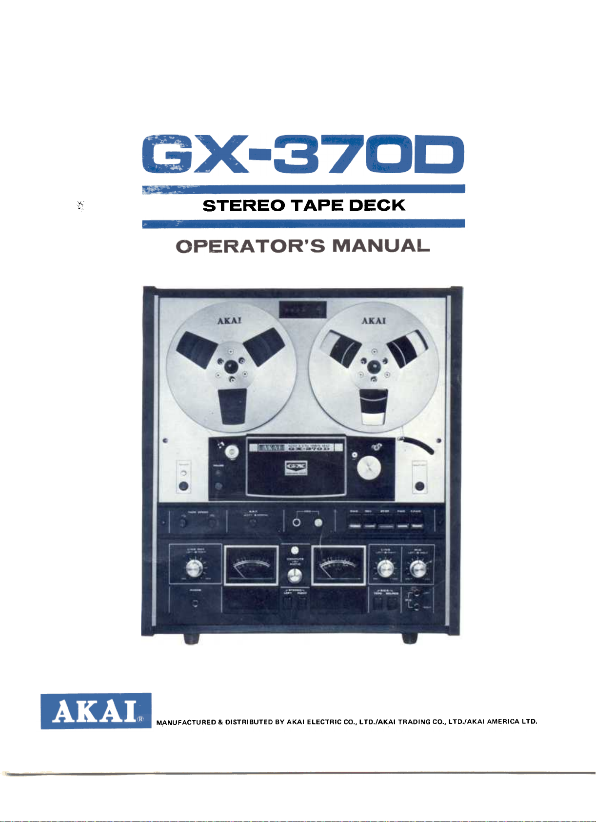
STEREO TAPE DECK
M,ANUFACTURED & DISTRIBUTED BY AKAI ELECTRIC CD., L TD./AKAI TRADING CO., L TD./AKAI AMERICA LTD.
Page 2
INDEX
Controls. Voltage & Cycle Conversion. Tape Speed Selection. Direct Function Change System. Fast Forward & Rewind AutomaticStop&Shut-Off Pause Control. Remote Control. Connections Operating Precautions TapeSelectorSwitch Recording Level Setting. Compute-O-Matic (automatic recording level control)
How To Use The Din Jack Head Cleaning. Pinch Wheel & Capstan Cleaning. Head Demagnetizing Sound Monitoring. Tape Erasing Tape Loading. : .
4-Track Stereo Recording/Playback System. 4-Track Monaural Recording/Playback System. Automatic & Manual Reverse Recording/Playback. .
Playback of Pre-Recorded Tape. Recording Using Microphones. Recording From An External Amplifier. Recording From A Turntable. Tape Dubbing. Sound-On-Sound Recording. Sound Mixing. Sound-With-Sound Recording. TapeSplicing&Editing Technical Data. , Standard Accessories Optional Accessories ",.,..""".",.,.,.",
2
4
4
4
4
4
4
4
5
6
6
6
6
6
7
7
7
7
8
8
8
8
8
9
10
11
11
11
12
12
12
13
14
14
w
Page 3
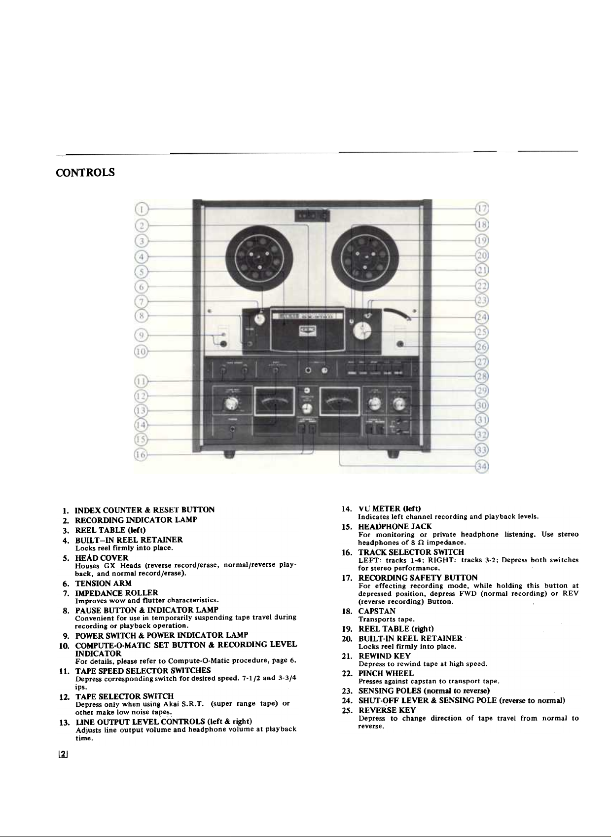
CONTROLS
I. INDEX COUNTER & RESET BUTTON
2. RECORDING INDICATOR LAMP
3. REEL TABLE (left)
4. BUILT-IN REEL RETAINER
Locks reel firmly into place.
5. HEAD COVER
Houses GX Heads (reverse record/erase, normal/reverse play-
back, and normal record/erase).
6. TENSION ARM
7. IMPEDANCE ROLLER
Improves wow and flutter characteristics.
8. PAUSE BUTTON & INDICATOR LAMP
Convenient for use in temporarily suspending tape travel during
recording or playback operation.
9. POWER SWITCH & POWER INDICATOR LAMP
10. COMPUTE-O-MATIC SET BUTTON & RECORDING LEVEL
INDICATOR
For details. please refer to Compute-O-Matic procedure, page 6.
II. TAPE SPEED SELECI'OR SWITCHES
Depress corresponding switch for desired speed. 7-1/2 and 3-3/4
ips.
12. TAPE SELECI'OR SWITCH
Depress only when using Akai S.R. T. (super range tape) or
other make low noise tal:>es..
13. LINE OUTPUT LEVEL CONTROLS (left & right)
Adjusts line output volume and headphone volume at playback
time.
~
14. VU METER (left)
Indicates left channel recording and playback levels.
15. HEADPHONE JACK
For monitoring or private headphone listening. Use stereo
headphones of 8 .n impedance.
16. TRACK SELECTOR SWITCH
LEFT: tracks 1-4; RIGHT: tracks 3-2; Depress both switches
for stereo performance.
17. RECORDING SAFETY BUTTON
For effecting recording mode, while holding this button at
depressed position, depress FWD (normal recording) or REV
(reverse recording) Button.
18. CAPSTAN
Transports tape.
19. REEL TABLE (right)
20. BUILT-IN REEL RETAINER
Locks reel firmly into place.
21. REWIND KEY
Depress to rewind tape at high speed.
22. PINCH WHEEL
Presses against capstan to transport tape.
23. SENSING POLES (nonnal to reverse)
24. SHUT-OFF LEVER & SENSING POLE (reverse to nonnaI)
25. REVERSE KEY
Depress to change direction of tape travel from normal to
reverse.
Page 4
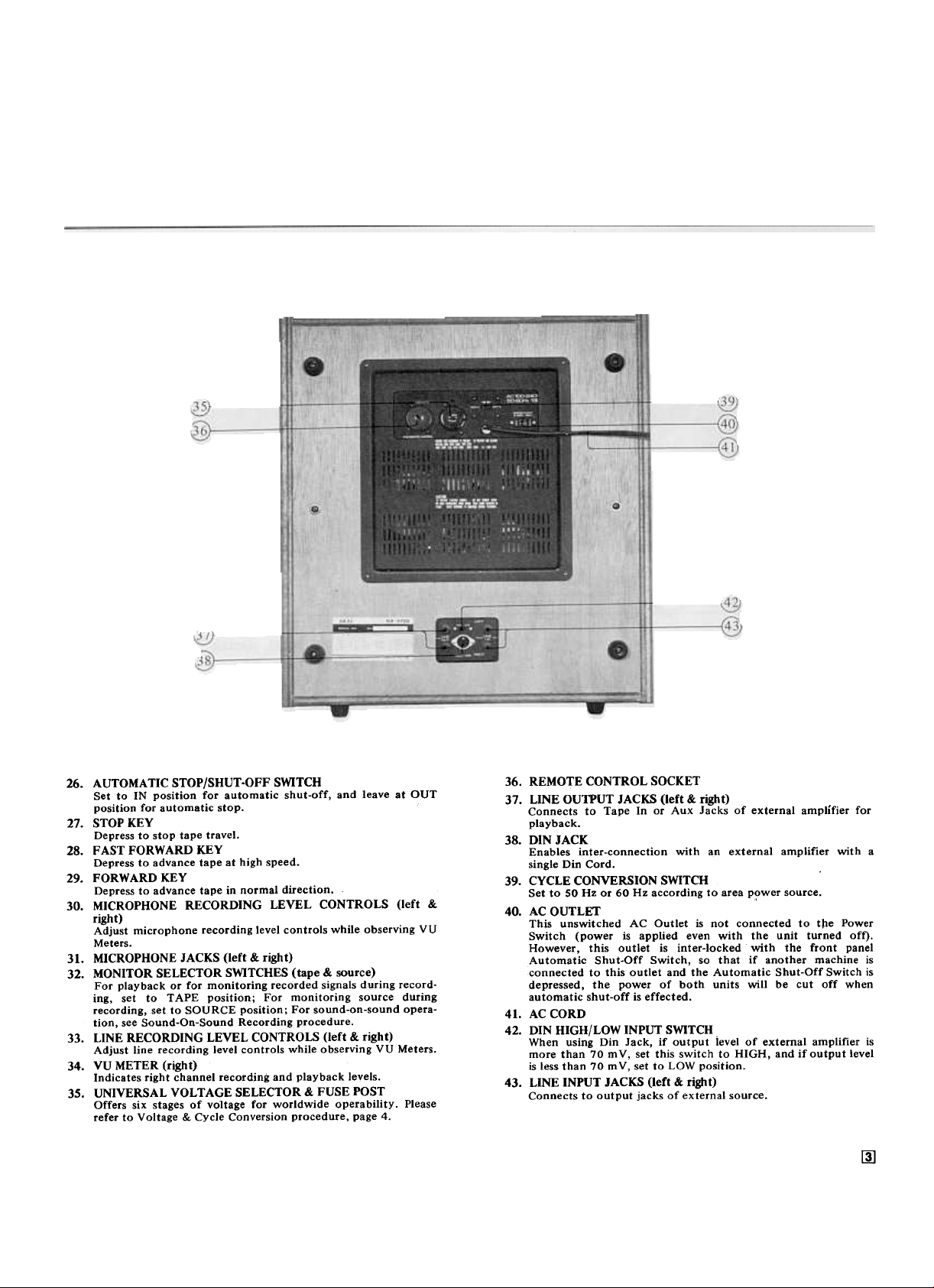
26. AUTOMATIC STOP/SHUT-OFF SWITCH
Set to IN position for automatic shut-off, and leave at OUT
position for automatic stop.
27. STOP KEY
Depress to stop tape travel.
28. FAST FORWARD KEY
Depress to advance tape at high speed.
29. FORWARD KEY
Depress to advance tape in normal direction.
30. MICROPHONE RECORDING LEVEL CONTROLS (left &
right)
Adjust microphone recording level controls while observing vI)
Meters.
31. MICROPHONE JACKS (left & right)
32. MONITOR SELECTOR SWITCHES (tape & source)
For playback or for monitoring recorded signals during recording, set to TAPE position; For monitoring source during
recording, set to SOURCE position; For sound-on-sound operation, see Sound-On-Sound Recording procedure.
33. LINE RECORDING LEVEL CONTROLS (left & right)
Adjust line recording level controls while observing VU Meters.
34. VU METER (right)
Indicates right channel record;ng and playback levels.
35. UNIVERSAL VOLTAGE SELECTOR & FUSE POST
Offers six stages of voltage for worldwide operability. Please
refer to Voltage & Cycle Conversion procedure, page 4.
36. REMOTE CONTROL SOCKET
37. LINE OUTPUT JACKS (left & right)
Connects to Tape In or Aux Jacks of external amplifier for
playback.
38. DIN JACK
Enables inter-connection with an external amplifier with a
single Din Cord.
39. CYCLE CONVERSION SWITCH
Set to SO Hz or 60 Hz according to area P?wer source.
40. AC OUTLET
This unswitched AC Outlet is not connected to tpe Power
Switch (power is applied even with the unit turned off).
However, this outlet is inter-locked with the front panel
Automatic Shut-Off Switch, so that if another machine is
connected to this outlet and the Automatic Shut-Off Switch is
depressed, the power of both units will be cut off when
automatic shut-off is effected.
41. AC CORD
42. DIN HIGH/LOW INPUT SWITCH
When using Din Jack, if output ievel of external amplifier is
more than 70 mV, set this switch to HIGH, and if output level.
is less than 70 m V, set to LOW position.
43. LINE INPUT JACKS (left & right)
Connects to output jacks of external source.
~
Page 5
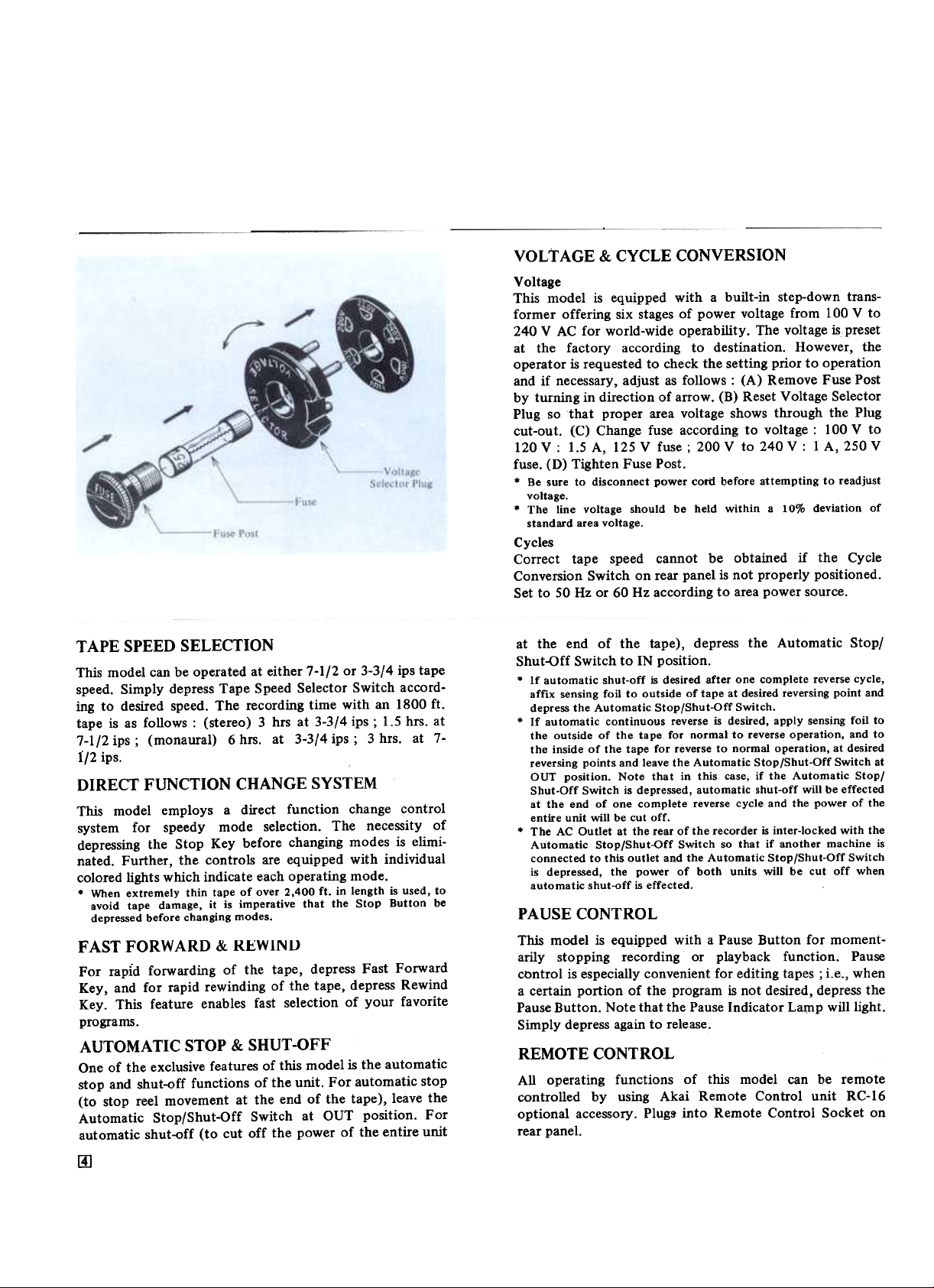
VOLTAGE & CYCLE CONVERSION
Voltage
This model is equipped with a built-in step-down trans-
former offering six stages of power voltage from 100 V to
240 V AC for world-wide operability. The voltage is preset
at the factory according to destination. However, the
operator is requested to check the setting prior to operation
and if necessary, adjust as follows: (A) Remove Fuse Post
by turning in direction of arrow. (B) Reset Voltage Selector
Plug so that proper area voltage shows through the Plug
cut-out. (C) Change fuse according to voltage: 100 V to
120 V: 1.5 A, 125 V fuse; 200 V to 240 V: 1 A, 250 V
fuse. (D) Tighten Fuse Post.
.Be sure to disconnect power cord before attempting to readjust
voltage.
.The line voltage should be held within a 10% deviation of
standard area voltage.
Cycles
Correct tape speed cannot be obtained if the Cycle
Conversion Switch on rear panel is not properly positioned.
Set to 50 Hz or 60 Hz according to area power source.
TAPE SPEED SELECTION
This model can be operated at either 7-1/2 or 3-3/4 ips tape
speed. Simply depress Tape Speed Selector Switch according to desired speed. The recording time with an 1800 ft.
tape is as follows: (stereo) 3 hrs at 3-3/4 ips; 1.5 hrs. at
7-1/2 ips; (monaural) 6 hrs. at 3-3/4 ips; 3 hrs. at 7-
i/2 ips.
DIRECT FUNCTION CHANGE SYSTEM
This model employs a direct function change control
system for speedy mode selection. The necessity of
depressing the Stop Key before changing modes is eliminated. Further, the controls are equipped with individual
colored lights which indicate each operating mode.
.When extremely thin tape of over 2,400 ft. in length is used, to
avoid tape damage, it is imperative that the Stop Button be
depressed before changing modes.
FAST FORWARD & REWINU
For rapid forwarding of the tape, depress Fast Forward
Key, and for rapid rewinding of the tape, depress Rewind
Key. This feature enables fast selection of your favorite
programs.
AUTOMATIC STOP & SHUT-OFF
One of the exclusive features of this model is the automatic
stop and shut-off functions of the unit. For automatic stop
(to stop reel movement at the end of the tape), leave the
Automatic Stop/Shut-off Switch at OUT position. For
automatic shut-off (to cut off the power of the entire unit
at the end of the tape), depress the Automatic Stop/
Shut-Gff Switch to IN position.
.If automatic shut-off is desired after one complete reverse cycle,
affix sensing foil to outside of tape at desired reversing point and
depress the Automatic Stop/Shut-Off Switch.
.If automatic continuous reverse is desired, apply sensing foil to
the outside of the tape for normal to reverse operation, and to
the inside of the tape for reverse to normal operation, at desired
reversing points and leave the Automatic Stop/Shut-Off Switch at
OUT position. Note that in this case, if the Automatic Stop/
Shut-Off Switch is depressed, automatic shut-off will be effected
at the end of one complete reverse cycle and the power of the
entire unit will be cut off.
.The AC Outlet at the rear of the recorder is inter-locked with the
Automatic Stop/Shut-off Switch so that if another machine is
connected to this outlet and the Automatic Stop/Shut-Off Switch
is depressed, the power of both units will be cut off when
automatic shut-off is effected.
PAUSE CONTROL
This model is equipped with a Pause Button for moment-
arily stopping recording or playback function. Pause
control is especially convenient for editing tapes; i.e., when
a certain portion of the program is not desired, depress the
Pause Button. Note that the Pause Indicator La~p will light.
Simply depress again to release.
REMOTE CONTROL
All operating functions of this model can be remote
controlled by using Akai Remote Control unit RC-16
optional accessory. Plugs into Remote Control Socket on
rear panel.
[4]
Page 6
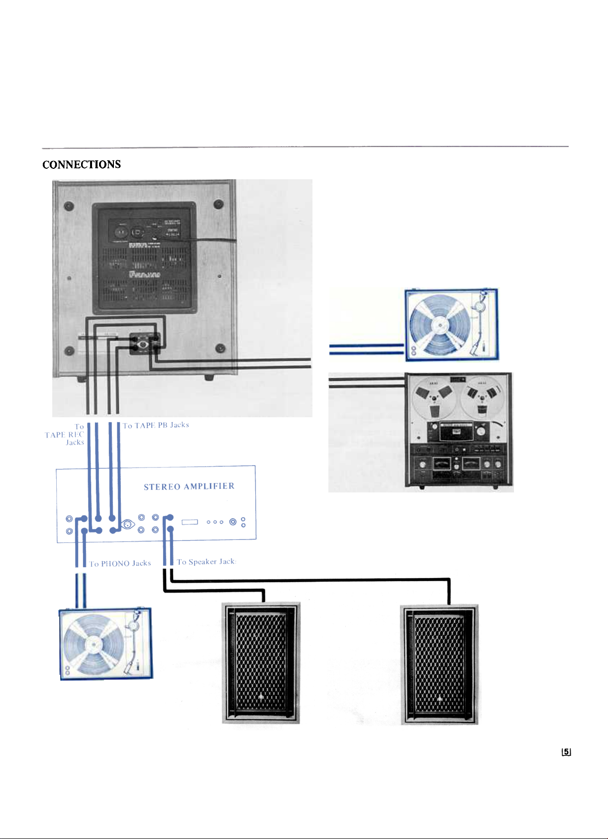
CONNECTIONS
~
Page 7

OPERATING PRECAUTIONS
The following conditions do not indicate mechanical failure
of your unit. If your machine exhibits any of the following,
check for trouble as indicated.
Loss of sensitivity and tone quality
* AC power voltage lower than the voltage to which your
machine is adjusted.
* Magnetized heads.
* Wrong side of tape facing heads, or defective or worn
tape.
Machine will not record or play
* Check positions of controls, input and output connec-
tions and plugs.
* Tape is not loaded properly.
* Machine is set to pause mode.
* Trouble with the connected machine.
Irregularity in tape transport
* When extremely thin tape of over 2,400 ft. in length is
used, to avoid tape damage, it is imperative that the
Stop Button be depressed before changing modes.
* Oil on capstan. Please refer to Pinch Wheel & Capstan
Cleaning procedure.
* Sticky or dirty tape surface.
* Tape is not loaded properly.
Does not turrt on eventhough the Power Switch is depressed
* Check AC Cord.
* Machine is set to automatic shut-off.
* Fu~e is blown.
The following notes are provided for your convenience.
* Place machine on a flat horizontal surface and operate
either horizontally or vertically.
* Do not place anything on top of your machine which
will obstruct the ventilator.
* Should there be a problem with your machine, write
down the model and serial numbers and all pertinent
data regarding warranty coverage as well as a clear
description of the existing trouble and contact your
nearest authorized Akai Service Station or the Service
Dept. of Akai Electric Company, Tokyo, Japan.
TAPE SELECTOR SWITCH
This model is equipped with a Tape Selector Switch. Use of
this switch brings out the maximum response of high
performance low noise tapes and works to change the
recording equalization according to the tape. The combi-
nation of the Akai GX Head and low noise tape has enabled
startling progress in tone quality. Use for low noise tape
only.
RECORDING LEVEL SElTlNG
For precise setting of the recording level, monitoring
through headphones is recommended. Connect stereo head-
phones to the Headphone Jack, and depress SOURCE
Seley tor Switch. Adjust the Recording Level Controls while
observing the VU Meters and keep the recording level as
high as possible within the yellow part of the meter scale.
* If SOURCE Selector Switch is depressed, the input level can be
adjusted before setting machine to recording mode. However, if
TAPE Selector Switch is depressed, the input level can be
adjusted only after setting machine to recording mode.
COMPUTE-o-MATIC (automatic recording
level control)
In the past, when making a recording, in order to obtain an
optimum recording level, the operator had to adjust the
input controls by hand while observing the VU Meters. The
new Akai Compute-O-Matic system does the job for you in
that when the Compute-O-Matic Set Button is depressed
during recording mode, the maximum sound level is
automatically adjusted to "0" VU and then other levels are
adjusted proportionately. In other words, when this button
is depressed, the Recording Level Indicator automatically
stops at maximum. This maximum level becomes "0" VU
and other levels are proportionately adjusted. Note that this
system differs from ordinary so called "automatic gain
control" systems which merely keep the sound within a
certain midrange level.
HOW TO USE THE DIN JACK
The Din Jack at the rear of the machine can be used instead
of the Rec. and P .B., Jacks if your amplifier has a
corresponding connection. This one cord system eliminates
the necessity of four separate connections and disconnec-
tions. When recording from an external amplifier, if the
output of the amplifier is more than 70 mY, set the Din
Jack High/Low Input Switch to HIGH position. If the
output level is less than 70 mY, set to LOW position.
* Do not use DIN-DIN Jack for connection with other tape
recorders or decks.
.
~
Page 8

HEAD CLEANING
The GX Heads do not normaliy require cleaning. However,
if old tapes or tapes which have been spliced are used, head
cleaning is recommended. Clean by rubbing the entire head
surface (do not scratch) with a cotton swab stick which has
been dipped in Akai cleaning fluid from Akai Head Cleaning
Kit HC-500.
PINCH WHEEL & CAPSTAN CLEANING
If foreign matter is allowed to accumulate on the Pinch
Wheel and Capstan, these particles will come off on the tape
causing deterioration of sound quality. Oil adhering to the
capstan also causes irregularity in tape transport. It is,
therefore, recommended that these parts be wiped clean
occasionally. For pinch wheel and capstan cleaning, use
Akai Cleaning Kit HC-500, or if this is not available, use
alcohol.
* Do not use chemicals such as chlorothane, etc., as the rubber
wheel will deteriorate.
HEAD DEMAGNETIZING
Normally, the steel pole pieces which form part of the
recording and playback heads become slightly magnetized.
The effect of magnetization is that it causes considerable
drop-out or introduces noise into your recordings. It is,
therefore, recommended that head demagnetizing be per-
formed periodically. This can be accomplished with a bulk
head demagnetizer by bringing it close to the heads and
making several circular motions over all head surface areas
as well as the head housing.
.Be sure to cut off the power of the unit prior to demagnetizing
the heads.
.Do not use magnetized tools in the vicinity of the heads.
SOUND MONITORING
This model is provided with a Headphone Jack and Monitor
Selector Switches so that sound source or recorded signals
can be monitored. For monitoring P!ogram source during
recording, depress SOURCE Switch. If the TAPE Switch is
depressed, the recorded signals will be monitored as the
tape passes the Playback Head. For private headphone
listening, connect an 8 .11 impedance stereo headphone and
depress TAPE Switch.
lIJ
Page 9

4- TRACK STEREO
RECORDING/PLAYBACK SYSTEM
STEREO
Track 1 .Stereo L 1- Track 1 L 1 -
4-track stereo recording/playback system requires the
simultaneous use of two tracks. For stereo operation,
depress both Track Selector Switches. The first recording/
playback takes place on tracks I and 3 and the second on
tracks 2 and 4 after the recorder has been set to reverse
mode.
I = I I I
2 R2-
;j
4 LOl-
-
I I
Stereo Al-
~ n~~
TAPE ERASING
Any signal information previously recorded on a tape will
be erased automatically as a new recording is made. For
erasing only, thread the tape and set machine to recording
mode. No plugs should be connected to the input jacks and
recording level controls should be kept at minimum. ,Akai
Tape Eraser ATE-7 is recommended for quick and complete
erasure.
TAPE LOADING
Place a full reel of tape on the Supply Reel Table and an
empty reel on the Take-Up Reel Table. Thread the tape as
illustrated by the dotted lines in the figure anq lock reels
into place with the Reel Retainers provided on reel shafts.
4-TRACK MONAURAL
RECORDING/PLAYBACK SYSTEM
MONAURAL
Track 1r=::.: ::JMono 1 -.
2 4-
~
;s
-4 -:l- r I
4-track monaural recording/playback sequence is 1-4-3-2.
For monaural operation, depress LEFT Track Selector
Switch. The first recording/playback takes place on track 1
and the second on track 4 after the recorder has been set to
reverse mode. For recording/playback on track 3-2, depress
RIGHT Track Selector Switch. The third recording/
playback takes place on track 3 and the fourth on track 2
after the recorder has been set to reverse mode.
[§]
..I --I
..-
,,-
AUTOMATIC & MANUAL REVERSE
RECORDING/PLA YBACK
For automatic reverse recording or playback, affix about a
2.5 cm (l'j long piece of metallic sensing foil to the
outside of the tape at desired reversing point. If continuous
reverse between two points is desired, affix another piece of
sensing foil to the inside of the tape at desired reversing
point. In other words, affix a piece of sensing foil at each
end of the tape (outside of tape for normal to reverse
operation, and inside of tape for reverse to normal
operation). As the sensing foil passes the sensing poles,
reverse is effected.
* Your machine is also equipped with a Manual Reverse Key for
your convenience.
For reference, see AUTOMATIC STOP & SHUT-QFF,
page 4.
Page 10

PLA YBACK OF PRE-RECORDED TAPE
A'-'
-9
y-
Please read the operating precautions carefully before
attempting operation. Connect the Line Oqtputs of the
GX-370D to the tape inputs of the external amplifier and
connect tw~ speakers to the amplifier. Connect power cord
and load a pre-recorded tape;
STEREO PLAYBACK
A. Turn on Power Switch.
B. Depress both LEFT and RIGHT Track Selector
Switches for stereo operation.
C. Select tape speed.
D. Depress TAPE Monitor Switch.
E. Depress FWD Key to begin playback.
F. Adjust left and right Line Output Level Controls and
external amplifier controls.
G. Depress REV Key for reverse playback.
H. Depress STOP Key to stop playback.
---~
MONAURALPLAYBALK
Only the left channel is used for monaural playback.
Substitute the following steps for steps B, F, and G of
stereo playback procedure.
Tracks 1-4
B. Depress LEFT Track Selector Switch.
F. Adjust left Line Output Level Control and external
amplifier controls.
G. Depress REV Key for playback on track 4.
Tracks 3-2
B. Depress RIGHT Track Selector Switch.
F. Adjust left Line Output Level Control and external
amplifier controls.
G. Depress REV Key for playback on track 2.
~~
~
Page 11

RECORDING USING MICROPHONES
Please read the operating precautions carefully before
attempting operation. Connect power cord and load a tape.
STEREO RECORDING
A. Turn on Power Switch.
B. Depress both LEFT and RIGHT Track Selector Switch
for stereo operation.
C. Select tape speed.
D. Set Index Counter to "0000". This provides an easy
reference for locating positions on the tape.
E. Insert microphones into left and right Microphone
Jacks. Maintain a distance of at least 2 meters (7 ft.)
between microphones.
F. Depress SOURCE Monitor Switch.
G. Adjust and balance recording input level with left and
right Microphone Recording Level Controls while
observing corresponding VU Meters. Normal recording
level should not exceed "0" VU.
H. When an optimum recording level has been determined,
while holding Recording Safety Button at depressed
position, depress FWD Key to begin recording. Note
that the Recording Indicator Lamp will light.
I. To stop recording depress Stop Key.
J. For reverse recording, while holding Recording Safety
Button at depressed position, depress REV Key.
I1Q/
MONAURAL RECORDING
Only the left channel is used for monaural recording.
Substitute the steps B, E, G and J of stereo recording
procedure for the following step~.
Tracks 1-4
B. Depress LEFT Track Selector Switch.
E. Insert microphone into left Microphone Jack.
G. Adjust and balance recording input level with left
Microphone Recording Level Control while observing
the left VU Meter.
J. For reverse recording on track 4, while holding
Recording Safety Button at depressed position, depress
REV Key.
Tracks 3-2
B. Depress RIGHT Track Selector Switch.
E. Insert microphone into left Microphone Jack.
G. Adjust and balance recording input level with left
Microphone Recording Level Control while observing
the left VU Meter.
J. For reverse recording on track 2, while holding
Recording Safety Button at depressed position, depress
REV Key.
Page 12

RECORDING FROM AN EXTERNAL
AMPLIFIER
If an external amplifier or tuner amplifier is used, connect
the tape outputs of the external amplifier to the Line
Inputs in step E of stereo recording procedure.
RECORDING FROM A TURNTABLE
To record from a stereo or monaural disc, a crystal pick-up
can be connected directly to the Line Inputs in step E of
stereo recording procedure. If a magnetic or similar
cartridge is used, it must be connected to the Line Inputs
through an external amplifier.
TAPE DUBBING
When dubbing tape from another recorder, connect the line
outputs of playback machine to the line inputs of the
recording machine in step E of stereo recording procedure.
SOUND-ON-SOUND RECORDING
For transfer of previously recorded material from one track
to another accumulating as many individual recordings on a
single track as is desired. Use for language training or
various interesting musical compilations.
First Recording
A. Turn on Power Switch. The Power Indicator Lamp will
light.
B. Confirm that there are no connections to the Line
Input Jacks.
C. With the Reset Button set the Index Counter to
"0000".
D. Depress LEFT Track Selector Switch.
E. Insert microphone into left Microphone Jack.
F. Depress SOURCE Monitor Switch.
G. Adjust left Microphone Recording Level Control while
observing left VU Meter.
H. While holding Recording Safety Button at depressed
position, depress FWD Key. to begin first recording;
i.e., DO-RE-MI.
I. When the first recording is complete, rewind tape to
starting point.
With the standard accessory l:onnection l:ord connect
the Din connector to the Din Jack and the black cord
Pin Plug to the left Line Input Jack.
Second Recording
J. Depress both Monitor Switches.
K. Depress RIGHT Track Selector Switch.
L. Increase Line Recording Level Control.
M. Connect stereo headphones to monitor first recording
on track 1.
N. While holding Recording Safety Button at depressed
position, depress FWD Key to begin second recording;
i.e., MI-FA-SOL.
O. Reset left Line Recording Level Control (decrease little
by little) until proper level is obtained.
The second recording is made. on track j as the rust
recording is monitored through headphones. The two
recordings. will be completely merged on track 3 ; i.e.,
DO-MI-RE-FA-MI-SOL.
Third and subsequent recordings are made in the same way
by switching LEFT and RIGHT Track Selector Switches.
For playback, set Track Selector Switch to track on which
last recording was made and depress the TAPE Monitor
Switch.
I!1J
Page 13

SOUND MIXING
For mixing microphone and line input signals, proceed as
follows:
A. Insert microphones into Microphone Jacks and connect
the line outputs of external source to the Line Input
Jacks.
B. Adjust microphone input level with Microphone
Recording Level Controls and line input level with Line
Recording Level Controls.
C. For playback, operate Track Selector Switch according
to tracks used in making recording.
SOUND-WITH-SOUND RECORDING
Sound-with-sound recording is accomplished in the same
way as Sound-On-Sound except that instead of transferring
from one track to another, the sound on track 1 is
monitored through headphones while the second recording
is made on track 3. This feature is especially convenient for
teacher/student repetition and comparison (teacher's voice
on track 1 and student's voice on track 3. For sound-withsound recording, follow Sound-On-Sound recording procedure, substituting the following step for step L, and
eliminating step O.
L. Decrease Line Recording Level Control to minimum.
~
For playback, depress both Track Selector Switches (for
stereo) and depress the TAPE Monitor Switch.
TAPE SPLICING & EDITING
Cut tape diagonally with an overlap so that the ends are
lined up. Cutting tape on diagonal eliminates detection of
splice in recording. Cover aligned ends with splicing tape.
Press firmly exerting pressure to secure ends evenly. Trim
off excess splicing tape cutting into tape very slightly. This
eliminates the possibility of a sticky splice. For easy and
smooth tape splicing, Akai Tape Splicer AS-3 is highly
recommended.
~
Page 14

TECHNICAL DATA
Track System.
Reel Capacity.
Tape Speed. ..
Wow & Flutter
Equalization
Frequency Response
Distortion
Signal- To-Noise
Ratio. Erase Ratio. ..
Bias Frequency
Heads.
Motors
..4-track 2-channel stereo/monaural
..Up to 7" reel
..7-1/2 and 3-3/4 ips (:to.5%)
..Less than 0.07% RMS at 7-1/2 ips
Less than 0.10% RMS at 3-3/4 ips
..Correct equalization for playback
of tapes recorded to NAB curve.
..(Using Akai SRT Tape) : 20 Hz to
26,000 Hz (:t3 dB) at 7-1/2 ips,
30 Hz to 22,000 Hz (:t3 dB) at
3-3/4 ips. (Using Regular Tape) :
20 Hz to 24,000 Hz (:t3 dB) at
7-1/2 ips, 30 Hz to 19,000 Hz
(:t3 dB) at 3-3/4 ips
..0.8% (1,000 Hz "0" VU) using
Akai SRT Tape
58 dB using Akai ~Kr rape
Better than 70 dB
100 kHz
(3): Two GX combination recording
& erase heads, one GX
playback head
(3): 2-speed servo-control outer-
J"otor motor for direct capstan
drive, and two 6-pole eddy-
current outer rotor motors for
supply and take-up reel drive.
.tor improvement purposes, specitlcations and design are subject
to change without notice.
~
Page 15

STANDARD ACCESSORIES
Connection Cord. EmptyReel Sensing Tape Spare Fuse Operator's Manual.
.1 set
.Spare fuses are not included with CEE, CSA, and UL Standard
models.
OPTIONAL ACCESSORIES
UM-IO 1
Urn-Directional Dynamic Microphone
RC-16
DM-13
Non-Directional Dynamic Microphone
AS-3
1
1
1
1
ATE-7
-
Tape Eraser
ASE-22
~
Remote Control
ASE-:lU
Stereo Headphones Stereo Headphones
Tape Splicer
Page 16

L
Stereo Pre-Main Amplifier
Page 17

MANUFACTURED & DISTRIBUTED BY
AKAI ELECTRIC CO., LTD.
AKAI TRADING CO., LTD.
12.14, 2.chome, Higashi.Kojiya,
Ohta.ku, Tokyo, Japan
AKAI AMERICA LTD.
2139 E. Del Amo Blvd., Compton, Calif., 90220, U.S.A.
TEI.EPHONE: (213) 537.3880
TEI.EX: 67.7494
-
.
_:~ ,"
,-
Price US $1.50
:',,.,,{:.
,~:,:~i;;~
~
Printed in Japan
 Loading...