

Page 1
PULL SYNTHESIZED STEREO RADIO WITH
COMPACT DISC PLAYER DIGITAL
OPEN
DSP
P-EQ
A
U
MONO LOC MUTE
DIGITAL TIME
PMAM
POWER
LOUD
MANU/
SKIP
CLK SET
ST
RESET
COLOR
T
D
S
I
O
U
A
J
D
LOUD
1
PA U
DUAL TIME CAR COMPACT PLAYER
2
SCN
CDP
3
RPT4 SHF
5
CD
6
CD
HOUR
IR
AMS
MINUTE
EJECT
MODE BAND
Page 2

CONTENTS
Disassembly Instructions ..................................................................................................................................... 3
Disassembly Diagram.......................................................................................................................................... 4
Operation check................................................................................................................................................... 5
Block Diagram .....................................................................................................................................................6
Alignment Locations ............................................................................................................................................7
Alignment Procedures .........................................................................................................................................8
Printed Circuit Boards.......................................................................................................................................... 9
Wiring Diagram .................................................................................................................................................. 15
Exploded Views (Panel)..................................................................................................................................... 16
Exploded View Parts Lists (Panel) ....................................................................................................................17
Exploded Views (Cabinet) ................................................................................................................................. 18
Exploded View Parts Lists Cabinet) ..................................................................................................................19
Exploded View (Deck) .......................................................................................................................................21
Exploded View Parts List (Deck) .......................................................................................................................22
Schematic Diagram ...........................................................................................................................................24
Electrical Parts List ............................................................................................................................................ 26
Specifications..................................................................................................................................................... 32
Page
2
Page 3

DISASSEMBLY INSTRUCTIONS
1. Using the unlock key that came with the unit or a similar tool, unlock the Mounting Box and remove
toward the rear of the unit.
2. Remove the screw (A) located on the rear of the top cabinet then remove the Top Cabinet.
3. Remove two screw (B) located on the rear of the bottom cabinet then remove the Bottom Cabinet.
4. Remove two screws (C) (one located at the left side and one located at the right side of the Front
Bracket) then remove the Left Hook and the Right Hook.
5. Open the panel and remove the Ring and the Panel Bracket.
6. Remove the screw (D) from the main board and remove two screws (E) each side of the base then remove
the Base.
7. Remove two screws (F) from the Front bracket and remove two screws (G) from the Rear cabinet.
Remove two screws (H) from the front deck bracket then remove the Front Deck Bracket.
Remove two screws (I) from the Rear Deck Bracket then remove the Rear Deck Bracket and the Deck.
8. Remove four screws (J) and two screws (K) from the heat sink then remove the Heat Sink and IC 8568 Heat
Sink.
9. Remove the screw (L) and remove the Antenna Clip.
Remove the screw (M) and remove the Wire Clip.
10. Remove two screws (N) from the rear cabinet of the left side then remove the IC 7809 Bracket.
11. Remove four screws (O) from the main board then remove the Main Board.
12. Remove four screws (O) each side of the rear cabinet then remove the Front Cabinet and the Rear Cabinet.
3
Page 4
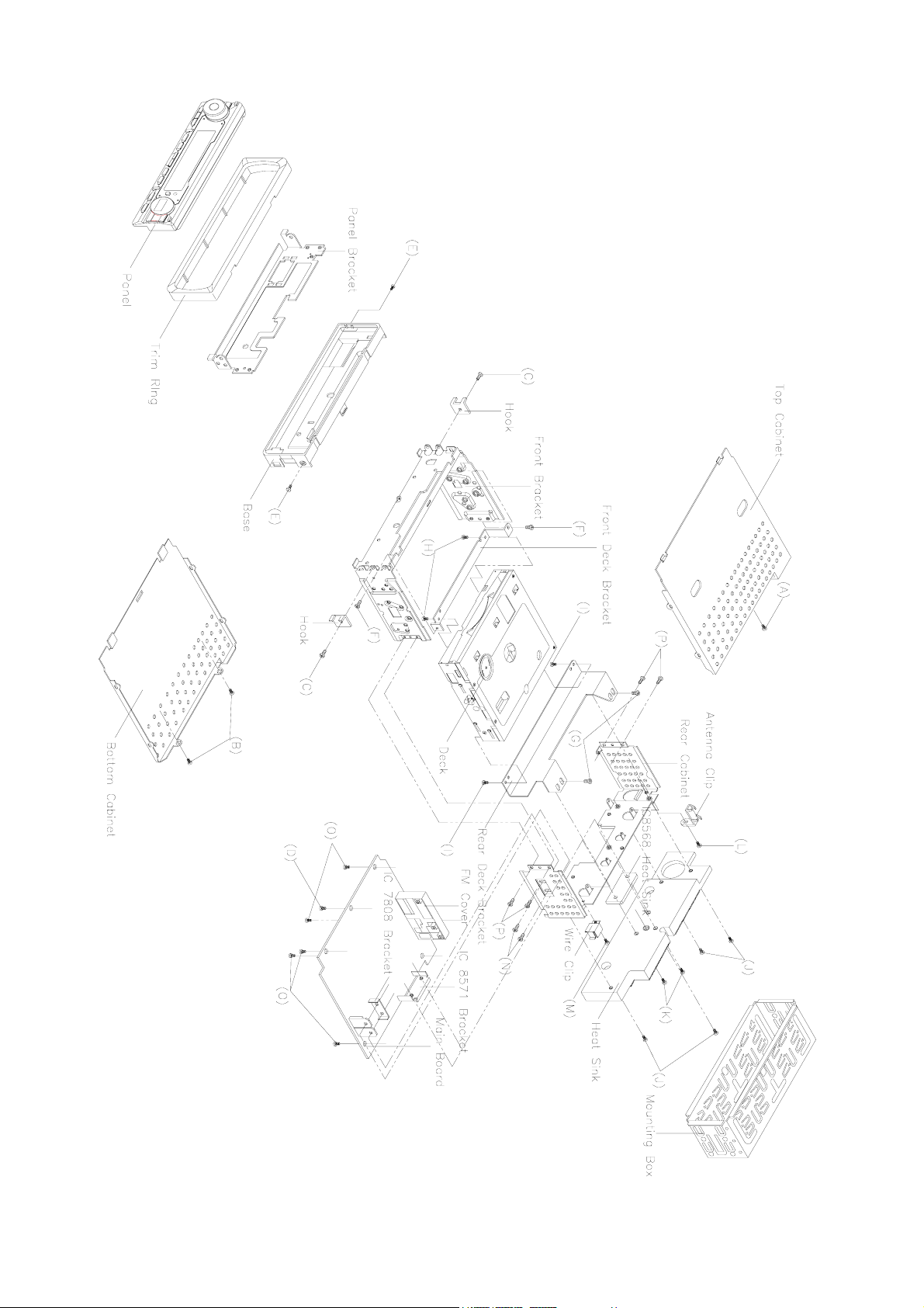
DISASSEMBLY DIAGRAM
4
Page 5
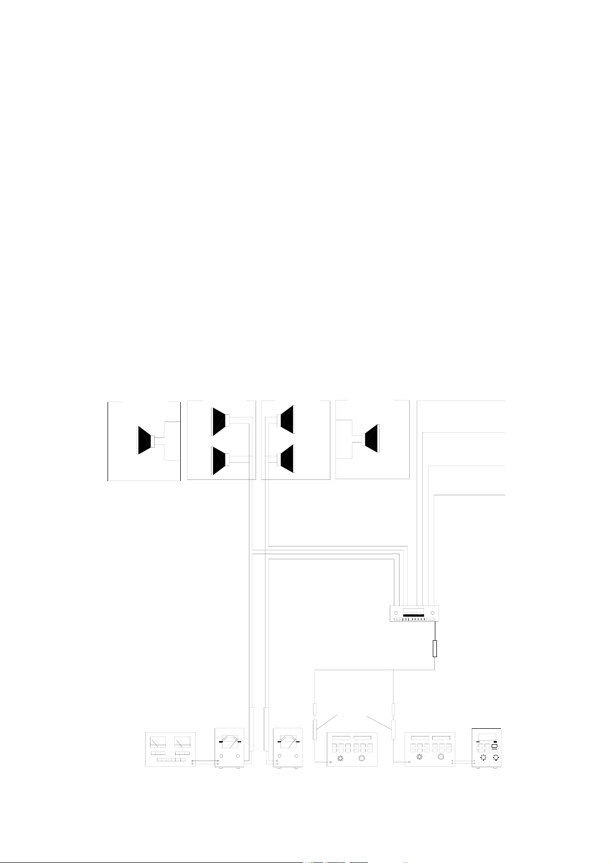
OPERATION CHECK
GENERAL SPECIFICATIONS OF SIGNAL
Standard frequency
Signal output
Modulation
AF output level FM/MW/LW
Power source voltage DC 14.0V (Backup voltage is the same as this)
AF load impedance 4 ohm pure resistance
Balance Center position of level
Tone Center position
The signal strength read in this section is voltage on the antenna.
Test Diagram
2-SPEAKER
FRONT
SPK.
FM
MW
LW
FM
MW
LW
MW
FM Stereo
4-SPEAKER
RL.
SPR.
FL.
SPK.
4-SPEAKER
RR.
SPK.
FR.
SPE.
98.1 MHz (87.5, 108 MHz)
1000 KHz (522, 1620 kHz)
200 KHz (144, 288 kHz)
1mV
5mV
5mV
400 Hz 30% MOD.
1 kHz 75 kHz DEV.
90% for L only or
R only pilot level 10%
2-SPEAKER
FRONT
SPK.
ACC (DV14.4V)
BACK UP (14.4V)
GROUND
DISTORTION
METER
VTVM
VTVM
DUMMY
ANTANNA
AM SG
MAIN UNIT
FM SG
POWER ANTANNA
ANT
MPX
STEREOS
MODULATOR
5
Page 6

BLOCK DIAGRAM
6
Page 7

FM/AM TUNER
ALIGNMENT LOCATIONS
7
Page 8

ALIGNMENT PROCEDURES
FM ADJUSTMENT
Equipment Required
z AM IF/RF signal generator
z Solid-state voltmeter (SSVM)
z Regulated DC power supply
z 2-CH voltmeter
z Distortion meter
FM Alignment Using FM Signal Generator
Note: Press the radio power switch to on the radio. Signal generator output must be kept as low as possible
to avoid overload and clipping.
Step Generator
Coupling
Stereo
Separation
FM SNC
Adjustment
STOP
SENS.
Note: The tuner module is well-adjust and adjustment is not recommended.
Signal
generator
to antenna
receptacle
98.1 MHz
Dev. 75 kHz
L+R=90 %
Int. 1 kHz
60dBµV output
Signal Generator
to antenna
receptacle
Generator Display
98.1 MHz
Int. 1 kHz
Dev. 75 kHz
L+R = 90 %
pilot = 10 %
98.1 MHz
@ 40 dBµ
98.1 MHz
Mod. 1kHz
Dev 75kHz
98.1 MHz VR1
98.1 MHz VR2
98.1 MHz
Setting
Adjustment Remarks
Adjust AF
output power
at maximum
separating
more than 30 dB
Stereo Separation
25 dB (±5 dB)
VR3
Adjust AF to stop
station.
8
Page 9

MAIN BOARD
PRINTED CIRCUIT BOARDS
9
Page 10

KEY BOARD
TOP VIEW
10
Page 11

KEY BOARD
BOTTOM VIEW
11
Page 12

CD SERVO BOARD
TOP VIEW
12
Page 13

CD SERVO BOARD
BOTTOM VIEW
13
Page 14

LAMP BOARD
14
Page 15

WIRING DIAGRAM
15
 Loading...