

Page 1
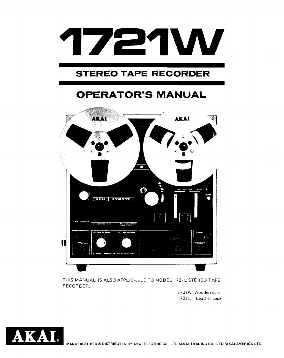
STEREO TAPE RECORDER
OPERATOR'S MANUAL
E!z!l
THIS MANUAL IS ALSO APPLICASLE TO MODEL 1721 L STEREO TAPE
RECORDER.
1 72 1 W Wooden case
1721 L Leather case
MANUFACTURED & DISTRIBUTED
BY
A<Al
ELECTRIC CO., LTD./AKAI TRADING CO., LTD./AKAI AMERICA LTD.
Page 2
INDEX
Controls
Voltage & Cycle Conversion
Tape Speed Selection
Fast Forward & Rewind
-4utomatic Shut-Off
Pause Control
Connections
Operating Precawtions
Taps Selection
Sound Monitoring
How To Use The Din Jack
Head Cleaning
Head Demagnetizing
TdpeLoading
4-Track Stereo Recording/Playback System
4-Track Monaural Recording/Playback System
Playback Of Pre-Recorded Tape
Recording Using Microphones
Recording From An External Amplifier
Recording From A Turntable 10
TapeDubbing 10
TapeErasing
Tape Splicing & Editing 10
Public Address System 10
Technical Data
Standard Accessories
Optional Accessories 12
.....................................
.....................
...........................
........................
............................
................................
..................................
..........................
................................
.............................
.......................
................................
...........................
.................................
.........
.......
..................
....................
............
....................
2
4
4
4
4
4
5
6
6
6
6
7
7
7
7
7
8
9
10
................................
.................................
10
.........................
..........................
................................
...........................
11
12
...........................
Page 3
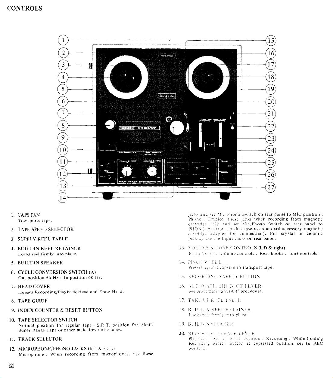
CONTROLS
1.
CAPSTAN
Transports tape
2.
TAPE SPEED SELECITOR
3.
SLPPLY REEL TABLE
4.
BUIL1'-IN REEL RETAINER
Locks reel firmly into place.
5.
BUILT-IN SPEAKEK
6.
CYCLE CONVERSION SWITCH
Out position
7.
HEAL) COVER
Houses Recording/Playback Head and Erase Hcad
8.
TAPE
9.
INDEX COUNTER & RESET BUTTOX
10.
TAPE SELECTOR SWITCH
Normal position for regular tape : S.R.T. position for Akai's
Super Range Tape or other make low nois? rapes.
11.
TRACK StLECTOR
12.
MICROPHONE/PHONO JACKS
Microphone : When recording from microyhon:j. us? these
GUIDE
50
Hz
:
In position
(A)
60
tleit
Hz.
h
II~~II
lack.
~n;
-;:
Phon.3
.
cartr:;i<r-
PHOXC,
carrrid,;: li3prtr for connection). For crystal or ceramic
pi;l;-.~
13.
1
Fr
14,
Pl\L
Pr:..:.
Ih,
I?
i?:
18.
EL
L,:.;---
19.
ELlL7.l\
20.
RLc,'i:I'
Pla:.
K
FOSII:
5~~1'~~:
:
1s:
(:ILL
\!E
rr
:.r i .
H
's,,
HE
ig-.r':
T
\I
;:I
I,:
.'-;:I.
ILT.I\
,
.
....
L;,:
r' : 2::
:.
Pi~,,no S\\~itch on rlar panel to
IJI~LCI
-ti;:.
~n.i
.!::,r.
12;.
Input
I
TI
I\F
\alum?
L
L
;ip-i3n
~
5-ur-Otf procedure.
'.ttL
'
*FL~
AKER,
.'LC\;
5::
:
jacks \vhen recording from magnetic
set \lic:Phono Switch on reor panel to
I,n
rii~s case use standard accessory magnetic
Jack,
on rear panel.
CO.YTKOLS
2onrroli ; Rear knobs : tone controls.
ro
transport tape.
:-I
1FI~
I.FX.ER
F:ET-\I~\FK
::r
i
rlac?.
:.ch
Lt\
:.
tK
1.9
:.:i,ir~vn
7
2:
:?yr?\s?d position, set to REC
-.
.
-
(Icft
&
right)
Recording : While l~olding
MIC
position
:
Page 4
21.
PAlSI
Ll
\
i
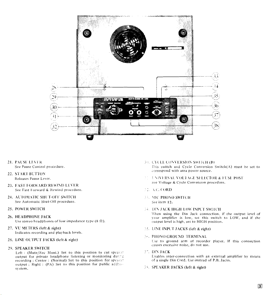
See Pauw Control procedure.
22.
S1':iKI HCTTUS
Release? Pause Lever.
23.
FASl'
See Fast 1.orward & Kewind procedure.
21.
iL IO\I
See Automat~c Sllut-Off procedure
25.
POWER SWITCH
26.
HEADPHONE JACK
Ute stereo headphone5 of low ~mpedance type
27.
VC
METERS
Indicate5 recording and playback levels
28.
LINF
29.
SPEAKER SWITCH
Left : (MuteIKt'c' Moni.) Set to this position to cut sp?s::output for private headphone listening or monitoring dur:-;
recording : Center : (Normal) Set to this position for sp?i:::-
output ; Right
s!
stem.
K
I-OKl\.\KD 'RE_\\'I\I) Lt\'EK
il
IC SHI T-OF.[ SM I ICFI
(left C right)
OLTPVT J,\C'KS
(left C right)
:
(PA)
Set to this position for public add::.
(8
R).
.:,I.
L1.C
1.k.
iO\\'ERSlO\
This
switch and Cycle Conversion S\vitcIi(A) must
Lorrespond with area power source.
I
\I\
I
K\
11
>ee Voltage & Cycle Con\ers~on procedure.
:.
pI.Iosi)
5?<
item
I:
Lll\SiCKHIGH L.O\.\'INPl:IS\$11C'II
\Illen using the Din Jack connection, if the output level of
yclur amplifier is low, set this switch to
output level is high, set to
.
.
.:.
LI\E
?r.
PHONO
Ise to ground arm of recorder player. If this connection
causes excessive noise, do not use.
I-.
DIS
JACK
Lnables inter-connection with an external amplifier by means
(of a single Din Cord. Use instead of
:*
SPE \KER JACKS
\
SWI'I'C
12.
INPIT J:iCKS
GROC'ND TER,\lINAL
OL1
(left
\(,I
13
S\+I
1C'ji
5.1
LtCTOII
HIGH position.
(left C right)
&
right)
(Bi
P.B.
CC
1
Jacks.
I
bI
LOW.
YOSI
and if the
he
set to
Page 5

VOLT-AGE & CYCLE CONVERSION
VOLT-ACE
Your niachin: is <qu~pp<d with a universal voltage selector
offfrlng
for
ac'sordlng ro d<sr:ca~;cn. How~ver, the operator is requested to sheik
readjust as
remove the Fuse Post
(2)
proper
(3) Change fus?
Fuse Post.
240
*
;Fuse
Post
CYCLE
Correct
Conversioc
screw
panel coucrrr-..:
IN or
power
original
Switc?
*
SIX
a
oild-a
stl<:tians
?d<
oi voltage from 100 V to 240 V A.C.,
ap<rablhr>.. Voltage
is
preset at the factory
serrlng Fricr ro operation, and if necessary
follows
:
I 1 I
Dismnnect power cord and
t.!
;:r:ninp
in direction of arrow.
Remove the \-olrag? S?;?:r~r Plug and reinsert so that
srta valrag?
V
:
0.5
To maintsir
machin?.
10%
I!
d?v~a[:s?-
r;i;-
dri\-2:
OL-T
i:.::;:
;;i:r.:r
13
Z:
Do
-8::
.T.:::-
;rr:-
~.
th?
:ilC
A.
..
5.
I:
-
I::.---
..
r
r?:r
:isL
.-r:r;:..:
1-
i;::;
:I
r-rr
rr
r
s5::i.s
7'3
;
::r+i:r.? u irh voltage and tighten the
1-
::
:3:
1-
(-5,
::r:.
.:z-:z::
:~:.r:r
::ti
I::
'L
.
..z
:
~
......
1-5 about
-
3:
zr
-.
..-.,
ST.\-:r:h must be rotated back to its
rnrough the Plug cut-out.
1-
:
-4. 125 V fuse ; 200 V to
-?ur;e
:-A:
:::j
and prolong the life of your
rh?
l~n?
voltage
be
\2113g?.
held within
b< obtained if the Cycle
r,ar properly positioned. With a
Conversion Switch (A) on face
-
li8
of a turn and move to
50
Hz operation according to area
:::?r b:ing reset. Cycle Conversion
:I
1:
r:::~
----
:e::rt?r
:i
must beset accordingly.
:n?
C>cle
Conversion Switches when
a
1
-
1
Fast
Forward
.AUTO.MATIC SHUT-OFF
One of the exclusive features of ths
shut-off function of the unit. Fa: r:rr:;r.: shut-off,
thread tape through Automatic
Automatic Shut-Off Switch to
comes to the end, the Shut-Off L:v?r
power of the entire unit will be cut of:.
rr.::?:
-5
r:t
;~iomatic
Sh~ri'ii L:..tr and set
OX p;r::::r. Q:tn rh? tape
..
.
-;.-.
:r:;
and the
TAPE
Th:
-
7-1
I
Th<
r;~
STERE
R.4L
For
fLi7
,:
LC
t
I
oF<r;:t
ard
-.-I-=-,
P.\L
SE
To
.:
bat.;
espe;.;-:.
to
51::
prog:-
mer,:
But:,::.
<PEEL# SELECTIOL
:;:-;rr2
T:L
-
I
. ~ .
C
1
:
T
-
-
I
-
.
,i.:.r
:
.
.
-:
.
-
-::
:-:
--;:I
::z-
.
:~_=
.:i
.
:r:.~
1
:"\::
-
-
-
if:
I
_
-::
. - .
yyr.
-
- : -
;:
:
r
---.:
::
r:.=-
rr
r..;.~
rpt speeds ; i.e., 3-314 and
i;?,:.
;:;at? rhe Tape Speed Selector.
---I
-r:xg IS00 ft. tape is as follows
I-> 2 .;s . 1.5
-
.;i
?
3.ri.. --1
:
T
:Z
1
:~<iate Fast ForwardIRewind
-::
:
ZT-
.IS
:-?id selections of recordings on
.r
;.:i
~to position and cannot be
?
:.
:ri
P:;i>-back Lever is in operation
- -
--
.
.r
-
_
-
:
_:
:-
.
-
--.
--
.
:.
L.
:
-.-a
;
:
-.:
.-,
.
r
.
-f::rg upward. Pause control is
:
-
?:.::rg rape during recording (lift
.
.-
.-.rr. a certain portion of the
?
?:-i-
1
:
:
--.?
re::rding level. Depress Start
hrs.,
7-112 ips. MONAU-
'2
ips.
during recording or play-
:,nrrol also permits adjust-
:
Page 6

CONNECTIONS
TAPE
----
STEREO
AMPLIFIER
Page 7

OPERATING PRECAUTIONS
The conditions listed below do not indicate mechanical
failure of your unit. If your machine exhibits any of the
following, please check for trouble as indicated.
Loss of sensitivity or tone quality.
*
Wrong side of tape facing heads.
*
AC power lower than the voltage to which your
machine is adjusted.
*
Duty heads. See Head Cleaning procedure.
*
Magnetized heads. See Head Demagnetizing procedure.
*
Defective or worn tape.
*
Low recording level.
Irregularity of tape transport
*
Dirty tape surface or oil adhering to capstan.
*
Bent take-up reel.
*
Tape loaded improperly.
*
Old or sticky tape.
Machine does not turn on even when Power Switch
*
AC plug disconnected.
*
Automatic Shut-Off Switch at ON position.
is
depressed
If your machine will not record or playback, check to
confirm that connections are correct and controls are
properly positioned. When using Din cord for connections
with
an
external amplifier, if recording is satisfactory but
playback cannot be accomplished, check the input of your
amplifier. In some cases, the input and output levels may
not match. Please use an amplifier of which the Din Jack
connection levels match.
*
Your machine requires constant voltage for optimum
performance.
*
If the sound sources are so far away from the
microphones that the recording level controls must be
turned up to maximum: some hum or noise will
inevitably be rtsorded.
.I
test recording is recom-
mended before attempting a final recording.
*
Should therf be a problfm with your machine, write
the model and serial number and all pertinent
down
data regarding
description
nearest
Dept. of
aurnv?riz:d .-\kai Service Station or the Service
.Il;jl
uirranty coverage as well as a clear
o:'
:hf fsisting problem and contact your
E:t::ric Company, Tokyo, Japan.
'T.APE
This
S.R
othclr
masir-,:.z
querc:.
is
reg:;:;ir
For
Su-:r.co
he:2-'-
t10\1
Th:
if
one-:
*
*
SELE(ITIO\
mid?:
.T.
;
r
i::.:
:;-:-
:ti; : .ir
..,,
;r;;
re:;
.
-
,
.
.
-
:-;:.
-1
-:- :
r.r,
..
-::r
s
,,,
.. .
.~.>
Ti'
ict
38.:-
::.
h.1
-r
>-;..:.::
I
r:
:
r-5
\\-:-
-.
>-:
.-
:
-<
r
-
.
.
:
C,L:
LC:.'.
D
re<,:-::-
:r
:I-.:.
r
:is
--
.
.
.::..f
~-
.
.
.
:.
-:
-
.
e;..:::;?d
:
;-
.
;--.-
-.~
-
.
:r
;::::
-
'.::-,:
r
.:
-~:
~.
-
n-irh a Tape Selector Switch. Set to
-.;.
i.cr
..sing
.Ikai's Super Range Tape or
rr:sc
ri7:i. This feature brings out the
:'r
:-.:gh
pclrformance low noise tape. In
----..
..$:.
rhs model displays a high fre-
-
r--
:r:.-.p
18.000
.
JN:,~:'
Hz
u-it h low noise tape. When using
I:-.:;
rn~rch at YORMAL position.
;r.;;:r
:
:
-
~
-.
TriE
::
:
~.
.
-.
\IUTE'REC'MONI position and
--
.~
-
->-
.....
1
.r;s2azce type
!)I\
.i~:
::sr:ad of the Rec. and P.B. Jacks
-:-
;c?r:?~ponding connection. Ths
r
i.
,r:- sliminares the necessity of four
.
.
-
.
.
.::
:-:
:
-:
:
7
.
.
Hz with regular tape, this
kadphone listening, set Speaker
tc? Headphone Jack. Use stereo
(8
R).
JACK
.
-.nccrion.
Il~n
-
r!,-t.
:-..,n
if the output
Jack
HIGHILOW
.;?I
ro
HIGH
position.
f,>r
operation with another
level
of
Switch to
Page 8

HEAD
i,'LE.4%ING
Accumulation of dust and magnetic particles on the heads
LII
results
poor head-to-tape contact and deteriorates sound
qualit>- and sensitivity. It is, therefore, recommended that
the heads be kept clean at all times. With a stiff cotton
swab dipped in cleaning fluid (Akai Head Cleaning Kit
HC-500
I
is highly recommended) rub the entire head surface
do
not scratch) until all tape oxide and dust are removed.
The capstan shaft, pinch wheel, tape lifter and other parts
over
whch the tape travels should also be cleaned
Yormally, the steel pole pieces which form part of the
recording and playback head become slightly magnetized.
The effect of magnetization is that it will cause
351s
drop out or introduce noise into your recordings. It is
consider-
recommended that head demagnetization be performed
2:riodically. This can be accomplished with a bulk de3s-gnetizer
by bringing it close to the heads and making
lekeral small circ.ular motions over all head surface areas as
bell as the head housing.
Be
sure to cut off the power of the unit prior to demagnetizing
the heads.
-
Both prongs of the demagnetizer should be covered with masking
rape to prevent the heads from being scratched.
*
Do not use magnetized tools in the vicinity of the heads.
*
Read the demagnetizer instructions carefully before operation.
TAPE LOADIEG
Place a full reel of tape on the Supply Reel Table and an
empty reel on the Take-Up Reel Table. Thread the tape as
illustrated by the dotted lines in the figure on page
8.
automatic shut-off is desired, thread the tape through the
Automatic Shut-Off Lever and set Automatic Shut-Off
Switch to
ON
position.
I-TRACK STEREO RECORDING PLAYBACK
SYSTEM
This model employs a 4-track stereo recording/playback
system which divides the magnetic tape into four tracks.
two of which are used simultaneously. The first stereo
recording/playback takes place on tracks 1 and 3, and the
second on tracks
Track 1
2
3
4
STEREO
I
I
I
2
and 4 after the reels have been inverted.
I
Stereo LI-,
R2c
Stereo R14
L2-
I
Track
1
L1-
P
If
4-TRACK XIONAURAL KEC:ORDINGIPLAYBACK
SYSTEM
\ionaural recordingj'playback sequence
monaural
recording/playback takes place on track 1 and the
second on track 4 after the reels have been inverted. The
thrd monaural recording/playback takes place on track 3,
2nd the fourth on track 2 after the reels have been'inverted.
MONAURAL
Track 1
Track
I
1
I
Mono
Mono
T-,
1
+
is
1-4-3-2. The first
Page 9

PLAYBACK OF PRE-RECORDED TAPE
Please read the operating precautions car:iully before
attempting operation.
STEREO
PLAYBACK
Connect power cord and load a pre-recorded 13F:.
A.
Turn on Power Switch.
B.
Set Track Selector to STEREO position.
C. Select tape speed with Tape Speed
D.
Set Speaker Switch on rear pans1 ta YORS1.AL
Sels:t-i.
position.
E.
Record/Playback Lever to
Set
FWD
position
to
begin
playback.
Adjust left and right Volume Controls.
F.
Adjust left and right Tone Controls.
G.
H.
To stop playback, return Record Pla) back L:xer to
vertical position.
*
Although this model is equipped with two built-in jpeakers. a pair
of external speakers can be connected
further enhance the performance of this
case the built-in speakers become
*
If a more powerful output is desired. the Lip.? Gur~ut Jacks can
be used for connecting to an external
to the Spe~ker Jacks to
model. Sote that in this
in ope rat^\-e.
ampl~fi?r.
MONACR.4L PL.4YBACK
For mor.a;?rii playback. substitute the following steps for
B.
F.
r7.d
G
si
steps
Tracks 1
B.
F.
G.
I.
Tracks
B.
F.
G.
I.
61
1
Se: Tr-;h S:le:tor to 1-4 position.
.\d::s:
::;r
.\d:i;s:
!:fr
lzx-:rr r::ls for playback on track 4.
3
6r
2
S:: Trxk Selector to
.\d:-;si
ri$t \-olume Control.
.\d:-sr r:ghr Tone Control.
Ir.;.err
r--.s
stereo procedure, and add step
\-olume Control.
Tone Control.
3-2
ior
>la\-back on track
position.
2.
I.
Page 10

RECORDING USING MICROPHONES
Please read the operating precautions carefully before
attempting operation.
STEREO RECORDING
Connect power cord and load a tape.
A. Turn on Power Switch.
Set Track Selector to STEREO position.
B.
C. Select tape speed with Tape Speed Selector.
D.
With Reset Button, set Index Counter to
provides an easy reference for locating positions on the
tape.
E.
Insert microphones into left and right Microphone
Jacks, and set
MIC position. Maintain a distance of at least
(7
ft.) between microphones.
Set Pause Lever by lifting upward.
F.
G.
While depressing Recording Safety Button, set Record
Playback Lever to REC position.
Adjust and balance recording input level with left and
H.
right Volume Controls while observing left and
VU Meters. Normal recording should not exceed
on either meter.
When an optimum recording level has been determined.
I,
depress Start Button to release Pause Lever and beg:
recording.
Mic/Phono Switch at rear of recorder to
000.
2
This
meters
righr
0
\.L-
To stop recording, return Recording/Playback Lever to
J.
vertical position.
Tone Controls have no effect during recording mode.
If microphones are used near the recorder, to prevent acoustic
feedback, set Speaker Switch to
MONAURAL RECORDING
For
monaural recording, substitute the following steps for
B,
sreps
step
Tracks
E.
E,
H.
L.
Track
3.
E.
H.
L.
E and H of stereo recording procedure and add
K.
1
&
4
Set Track Selector to 1-4 position.
lnsert microphones into left Microphone Jack, and set
Mic/Phono Switch at rear of recorder to MIC position.
Adjust and balance recording input level with left
Volume Control while observing left VU Meter.
Invert reels for recording on track 4.
3
&
2
Set Track Selector to
Insert microphones into right Microphone Jack, and set
IliiclPhono Switch at rear of recorder to MIC position.
Adjust and balance recoriiag input level with right
Volume Control while observing right VU Meter.
Invert reels for recording on track
MUTEIREC
3-2
position.
2.
MONI
position.
Page 11

KEciiKI:IfC;
FK09i
:2h
\r;>iTE;KN.-\i
:IMPLIFIEK
If an external amplifier or tuner ampli7.er is used, connect
the Line
amplifier instead of step
Input Jacks to the line outputs of the external
E
of stereo recording procedure.
This machine is equipped with an equalizer circuit and
front
panel Phono Jacks for direct recording from a
magnetic cartridge. Use standard accessory Magnetic
Cartridge Adapter and connect the outputs from turntable
cartridge to
recording procedure. and set
Mic/Phono Jacks instead of step E of stereo
Mic Phono Switch at rear of
recorder to PHONO positioc.
To record from a crystal pick-up
(0.5 V to 1
V)
or a
ceramic pick-up. connect the pick-up outputs directly to
the Line Input Jacks of this model instead of step E of
stereo recording pro:-dure.
*
Ground
Jrrn
If
this
i'onn?zrl,>n
:u:ntabl? to
;~US~S
Ground Terminal at rear of recorder.
excessive
noise, do not use.
Connect the line output jacks ot rh? plal-back machine to
Line Input Jacks
the
of thls mod?l instead of step E of
stereo recording procedure.
T.-IP~
Any signal
be erased
same tape.
recording
recorder in;?:;:
minimuni.
sor).) is
F.F.
x~i~i;
111.:
r::
:-.
aura-:~--:11!
Fc:
:;>ins
n~,.~,i:
\;.
L....
-1:;;.
t;.~.:.:.
r,.
:I
prcviousi!. recorded on a tape will
33
B
new recording is made on the
oni!. load tape and set machine to
;ll~i_~b
\11o~11d b? connected to the
..
.
;...I
:.>lume controls should be kept at
:.
7
17:
trdsei .IT€-7 (standard acces-
~
::.::-.:::,ifJ.
for
quick and complete
erasur?.
P.I\PE
Cut rap?
lined up.
the
tape.
Trim
Ths ~1imin;res
tap?
special:>be don?
PUBLIC .I\DDRESS
One of th:
converr
please
A.
B.
C. Turn
D.
E.
F.
SPLICI\G
5ig~c;:
C;:rr:rg
jph;:
;L
Pr:si
:~-rn:y
.i
EDITI$C
..iirh n dvfrlap so that the ends are
1.i;:
-2
diagonal eliminates detection of
r?c_rJ::g. Csvfr aligned ends with splicing
exeir!n pressure to secure ends evenly.
oii :I,-sss s?L::rg rjp:. cutting into tape very slightly.
r.:
?;#ss~bility of a sticky splice. Splicing
2sir.g
i:sis:sri
;i;.i~g.-,t
vzr;
57.
r:;airei
?szjbl? Tape Splicer AS-3, splicing can
.
.
Ilzrr..).
skillful work. With Akai's
SI'STEM
rr:-
I:irur?s of this model is the ability to
it
lni? r ?.~blic address system. For operation,
pro;:-3 3s rl';lsa-s
Conn:;r ~2,zsr :'1rd and turn on Power Switch.
Set Spzake; 5;~:::: ro P.A. position.
i-oltirr,;. C2nirols to minimum and insert micro-
SJ
phone(
into .\!!crophone Jack(s).
Set Jlic'Phono Sairch to MIC position.
U'hlle d?pr?sjing rh? Recording Safety Button set
Record, Playback
Adjust output level v\i:k \-olume Controls.
:
Lev?: to REC position.
Page 12

TECHNICAL DATA
Track System ....... 4-track 2-channel stereo/
monaural system
Reel Capacity
Tape Speed
Wow & Flutter
Equalization
Frequency Response 30 Hz to 21,000 Hz
Distortion.
Output Power
Signal to Noise Ratio . Better than 50 dB
Erase Ratio
Cross-Talk
Bias Frequency
Heads
.......
.........
......
........
.........
.......
.........
......... Better than 60 dB (monaural)
...... 63 kHz
.............
Up to 7" reel
7-112 and 3-314 ips (f2%)
Less than 0.14% RMS at 7-112 ips
Less than 0.18% RMS at
Correct equalization for playback
of tapes recorded to NAB curve.
(k3 dB)
7-11? ips (Akai SRT Tape)
at
(f
40 Hz to 15,000 Hz
at
3-314 ips (Akai SRT Tape)
30 Hz to 18,000 Hz
7-112 ips (regular tape)
at
40 Hz to 13,000 Hz
3-314 ips (regular tape)
at
Less than 2% (1000 Hz "0" VU)
10 W total music power (5 W/5 W) at
6 W continuous power (3 W/3
Better than 70 dB
Better than 45 dB (stereo)
(2) : One recording/playback
head & one erase head
3 dB)
(f
3 dB)
(k3 dB)
3-314 ips
W)
at
E
E
Motor
.............
Fast Forward
Rewind Time
Recording Capacity
Output Jacks Line (2) : 1.23 V ("0" VU)/30
&
.......
(1) : 2-speed induction motor
.....
.80/ 100 sec. using a 1200 ft.
tape at
60150 Hz
.
.
3 hours stereo recording using
a 1800
ft tape at 3-314 ips.
Required load impedance : more
than 10
Phone (1) : 100 mV/8 52
Speaker (2) : 5 W/8 R each
kR
......... Input Jack Microphone (2)
Line (2) : 1 50 mV/330 kR
Din
Speaker ........... 2 built-in 5 x 7" speakers
.".
Pswer Requirements . 100 V to 240 V A.C., 50160 Hz
-?
Power Consumption
D~mensions
U'elght
*
...........
Jack 1 V/ 1 5 mV
.... Semi-Conductors Transistors
.
.
.........
Diodes
50 W
(1721W) 358(W)x360(H)x248(D)mm
(172 1 L) 359(W)x366(H)x249(D)mm
:
16
:
4
(14 x 14.1 x 9.8")
(14.1 x 14.4 x 9.8")
............ (1 72 1 W) 13.2 kg (29 lbs)
(1721L)
For
improvement purposes, specifications and design are subject
to change without notice.
14 kg (30.8 lbs)
:
0.5 mV/ 100 kR
R
 Loading...