


1700
I
\L
AKAI TAPE
REGI|RDER
oo
AND
to
Molf Et
l7
l7
IASTE OF
CONTENTS
I
spEctFtcAnoNs..
.. ...'.....'......
I
I
HOW TO A.TEASURE DESIGNATED VALUES
OF
SPEC|F|CAT|ONS..,......
..............'
2
I
tocafloN oF coNlRor.s
..... . ..........................,
3
IV
DrsAssEMrLy
oF tApE TRANSPoRT uNtTs
AND AMPL|F|ERS.........
...... ... ...
,l
v
TRANSPORI
MECHAN|SL
.......... .....
6
IJ
ADJUSTMENT
OF
TAPE TRANSPORT
UNIT
................."..
9
II
ADJUSTMENT
oF
al4pr|FrER
... .................... .............'10
rlf
r,{A|NTENANCE
pRocEDURES .. ............. .............It
X(
Lrsl
or
REPLACEI
ENT
pARTs....................................12
X
ExpLoDED vtEw
oF coMpoNENt
p^RTs............ ......,.1,4
xI
TROU3LESHOOTTNG
CHART
................,..............,.21
n
scHEfiATtC DTAGRAM
.,.....,............, ..'.................25
xI
CoNNECTING DfAGRAl.r
...................-..--.-.-.-......-.26
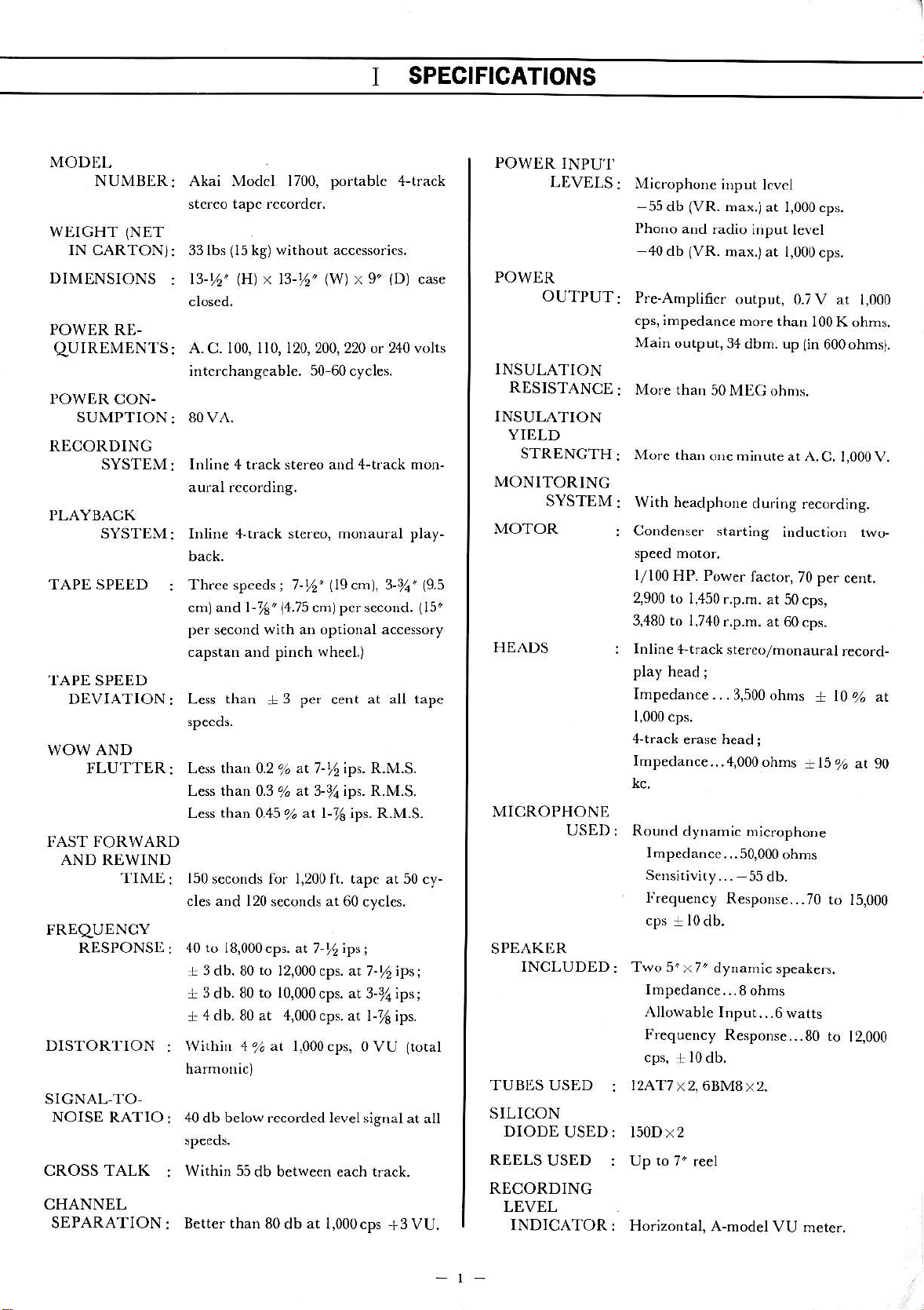
SPECIFICATIONS
MODEL
NUMBER
wtrGHT
(NET
IN CARTON)
DIMENSIONS
POWER RE-
qUIREMENTS
POWER CON.
SUMPTION
RECORDINC
Akai Modcl 1700, portablc 4-track
st.rco tape rccorder.
33 lbs
(15
kg) without acccssorics.
t3-t6'
lH)
x 13-%'
(w)
x 9'
(Dl
case
A. C. 100, ll0, 120,200,220 or 240 volts
interchang€abl€. 50 60cycles.
80VA.
Inline 4 t.ack st€reo and 4-tfack mon-
Inlin€ 4.tiack stefeo, monaural play-
Thrce speeds
cml and l-%"
(a.is
cmJ per second.
(15"
p€r
s€cond
with an optional accessory
capstan and pinch whe€I.)
SYSTEM:
PLAYBACK
SYSTEM:
TAPE SPEED
:
.I'APE
SPEED
DEVIATION
:
WOW AND
FLUTTER
:
TIME
FRDqUENCY
RDSPONStr
DISTORT'ION
SIGNAL-TO-
NOISE RATIO
CROSS TALK
CHANNEL
SEPARATION
Less
than
+
3
pef cent at all
tape
Less than 0.2
%
at 7-t6 ips. R.M.S.
Less than 0.3
%
at 3-7a ips. R.M.S.
Less than 0.45
%
at l-16 ips. R.M.S.
FAST FORWARD
AND
REWIND
150 seconds fof 1,200 ft. tapc at 50
cy-
cles
and 120
s€conds at 60 cyclcs.
40 to 18,000cps. at 7-%;ps;
.L 3 db.80
to
12,000 cps. at 7-l,
ipsj
+
3
db. 80
to 10,000cps.
at 3-3la;ps;
+
4 db. 80 at 4,000cps.
at l-7s ips.
Within 4%at l,000cps,oVU
ltotal
40 db below rccorded lev€lsignal
at all
Within 55db
between each trach.
Better than
80 db at l,000cps
+3
VU.
POWJ]R
INPU'I'
LDVELS:
POWDR
OUTPUT:
Microphone
ir)put lcvcl
-55
db
(VR.
max.jat
l,000cps.
Phono
and radio
input levcl
40 db
(VR.
max.)at l,000cps.
Pre-Amplifier
output, 0.7V at
1,000
cps, impedanc€
more than
l00K
ohms.
Main output,34dbm.
up
(in
600ohmt.
More than
50MEC ohns.
More
than
ore m;nute at A.C.
1,000V.
With headphor€
during reco.ding.
Condenser
start;ng
induction two-
l/l00HP.
Power
factor,70
pe.
cent.
2,900
to I,450
r.p.m. at 50
cps,
3,480 to 1,740
r.p.m.
at 60 cps.
lnline +tf ack
stereo/monau.al
record-
play h€ad
;
Impedance..
.3,500
ohms
+
l0
%
zt
I,000
cps.
4-track
erase head
;
Imp€danc€.
. .4,000 ohms
+15% at 90
Round
dynamic micropho.e
Impedance...50,000ohms
S€Dsit;vity...
55 db.
f.€quency
R€rpoDse...70
ro 15,000
Two 5'x7'
dynahic
speakers.
Imp€dance...8
ohms
Allowable IDput...6
warts
Frequency
R€sponse...8o
ro
12,000
cps,
:!
l0db.
I2AT7
x2, 6BM8x2.
l50Dx2
Up to 7'
r€el
INSULATION
RESISTANCE
INSULATION
YI[,LD
STRENGTH
MONITORINC
SYSTEM
MOTOR
HEADS
MICROPHONE
USED :
SPEAKOR
INCLUDED:
TUBES USED
:
SILICON
DIODE
USED:
REELS
USED :
RECORDING
LEVEL
INDICATOR
: Horizontal,
A-model
VU m€te..
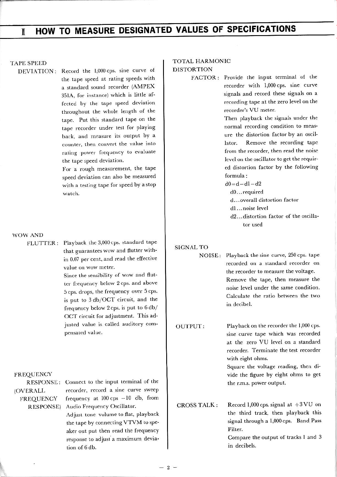
1I
IIOW
TO
NIICNSURE
DESIGNATED
VALUES
OF
SPECIFICATIONS
TAI'I] SPDtrD
DEVIATION
:
\{OW
AND
FLUTTER
:
Reco.d
the l,000cps.
sine
curve
of
the tap€
speed
at rating
sp€eds
with
a standa.d
sound
recorder
(AMPEX
351A,
for instance)
which
is little
af-
fccted
by lhe
tape sPecd
deviation
tlrroughout
the
whole
i€ngth
of the
tape.
Put
th;s standard
taPe
on
th€
tapc recorder
unde.
test
for playing
back, and
nreasure
its
outPut
bY a
couDte.,
then
codvert
thc value
into
rating
power
frequeDcy
to cvaluate
the tape speed dcviatior.
Fo.
a rough
measurement,
the
taPe
spe€d deviation
can also
be measured
with a testing
tape for
speed by
astop
Playback
thc 3,000cps
sianda.d
tape
that guarante€s
wo\d and flutter
with-
h 0.07
p€r cent,
aid read
the effect;ve
valuc
otr wow
mere.
Since
the sedsibility
of
wow and flut-
tcr frequency
bclow
2cps
and above
5 cps. d.ops,
the frequency
over 5cps.
is put
to 3db/OCT
circuit,
and
th€
frequency
bclow 2.ps.
is put
to 6db/
OCT circuit
for adjustment
This ad-
justed
value is
called
auditory com-
Connccr
to
thc input
tcdninal of
the
rcco.dcr,
.ccord a sine
curve swecp
f.equency
at 100 cps
-10
db.
from
Audio
frequency Oscillator.
Adjusl toDe
volume
to
flat,
playback
the tape
by .onnectidg
VTVM
tosp€-
aL€r out
put then read
the frequency
response
to adjusl a
maximum
devia'
}.RLqUI]NCY
RESPONSE:
(OVI]RALL
I'REqUENCY
RESPONSE)
TOTAL HARMONIC
DISTORTION
FACTOR:
Provide
the input
terminal
ol the
,ecord.r
with 1.000.ps.
':nF ,
urvF
signals and
.ecord
these signals on
a
recording
tape at
the zero level
on the
recorder's
VU mete.
Then
playback
the siSnals
under the
no.mal recording
condit;on
to meas-
u.c the distortion
factor
by an oscil
lator.
Remove
the recording
tapc
from
the recorder,
then read the
noisc
lcvelon
the oscjllator
to
8ct
the requ;r-
€d dhtortion
factor
by the following
formula:
d0:d-dl d2
d0..required
d...overall
distortion
factor
dl...noise
l€vel
d2...disto.tion
factor of
the oscilla-
to.
uscd
SICNAL
TO
NOISE: Playback
the sine curve,
250 cPS.
tape
rccorded on a
standard recorder
on
th€ reco.der
to measur€
the voltag€
Removc
the taPe, then measure
the
noisc level under
the same condition
Calculate
the ratio between
the two
in d€cibel.
OUTPUT:
I'layback
on the recorder
thc 1,000 cps.
sine
curvc tape
which
was
record€d
at
the zero VU
level on a standard
recorder.
T€rDinatc the
test recorder
with
€ight
ohms.
Square
the voltag€
rcading, then di
vide the figure
by eight ohms
to get
thc r.m.s.
Powcr
output.
CROSS
TALK:
Record 1,000 cps.
signal at
+3VU
on
the
third tack, then playback
this
signal
through a
l,000cps. Band
Pass
Filter.
Compare
the output
of tracks
I
and
3
in decibels.
2-
f
I
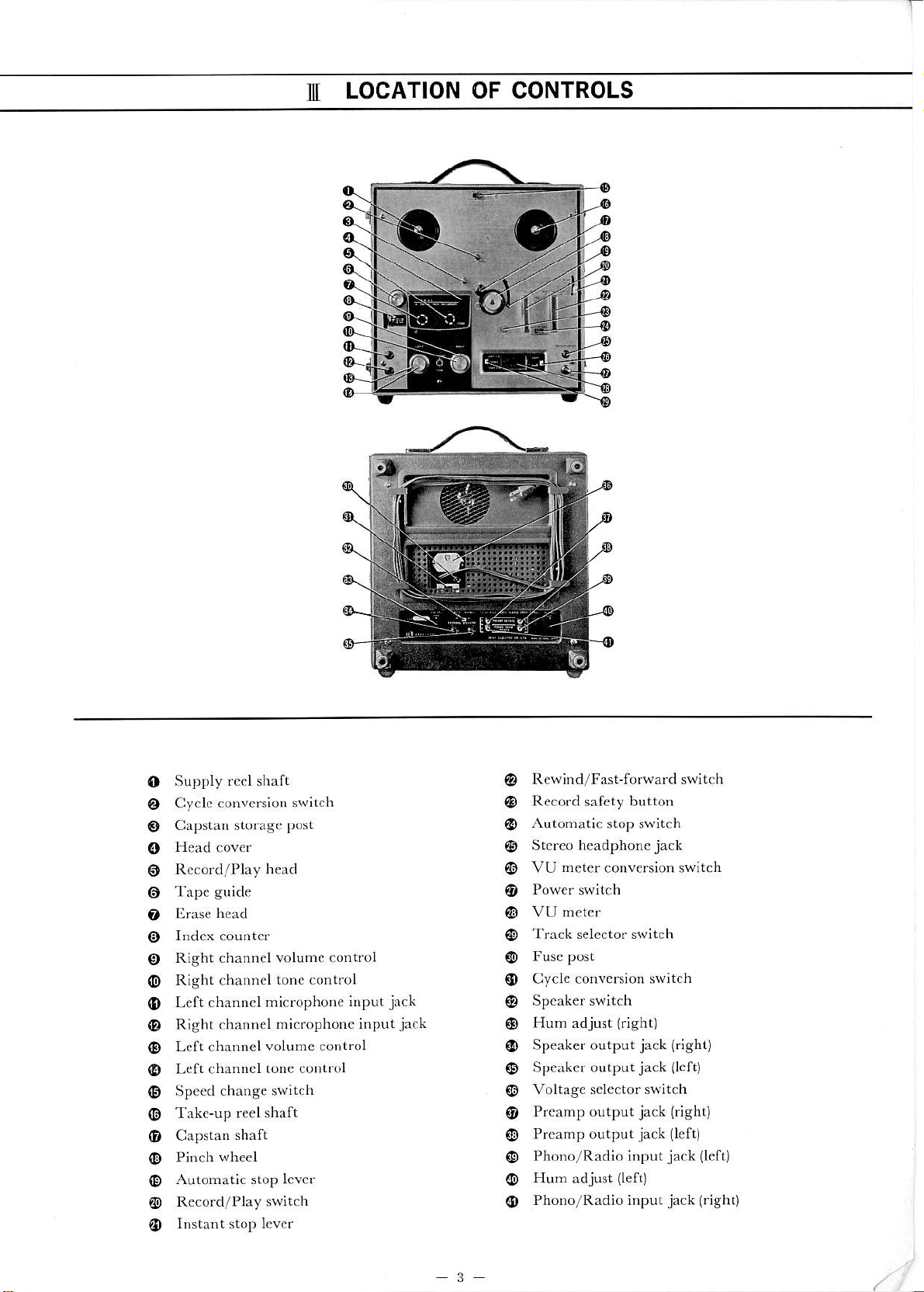
LOCATION OF CONTROLS
@
@
@
(D
(D
o
@
@
o
o
o
0
@
@
o
o
@
o
@
o
@
@
@
(D
(D
@
@
Supply
rccl shaft
Cyclc
convcrsion switch
Capstan storage
post
Tape
guide
trras€
head
Right channel volumc control
Right channel
tonc control
Left channcl
microphone
input
jack
Right channel
microphone input
jack
Left channel
volumc cont.ol
Left channel
tone control
Speed
change switch
Take-up reel shaft
Capstan
shaft
Pinch
wheel
Automatic stop lever
Record/Play switch
Rewind/FasFforward switch
Record safety button
Automatic
stop switch
Stereo headphonejack
VU
h€ter
conv€rsion switch
Track s€lector switch
Cycle conversion sw;tch
Hum adjust
(right)
Speaker output
jack (righr)
Speaker output
jack
llert)
Voltage
sele.tor switch
Preamp output
jack (right)
Preamp output
jack
{left)
Phono/Radio input
jack (l€ft
Hun
adjust
(left)
Phono/Radio input
jack
(rish0
3
I\I
DISASSEMBLY
OF TAPE TRANSPORT
UNITS
& AMPLIFIERS
ll l-oo!',, rh. lt l:.1.\ I\ lN(;
SUIlll\f
irlof
I'INCIt R()L-
LI{l , ,lt-'.. ,\vl,v ," !i
ih. l'IN(ill lt()l.l.l lt
llil.
13)
L,{iJ.!
thc S(lltli\\'S
nrxrl.(l 1,,,))
r.ri r(j
t{ll
i,r
('(1,.r
ro
r.!!^! l)1'lCK
l).\\l.ll.
tl)1.
12
l.(.,,,,tr | tlx. I)llUK
C( )\ l R( )I- ti\( )lls
ialrnd iblby
io,!c,,i,ig d,cif ritx;fing
s.raL. u';i)g
r
I)liillips
h.adcd
o
99
r.t
I
('11
l.oosci
(h(i
S(iltl:,\\'S,,)rrk.d
f,or)
i.t
r,)
ktr.
I
(5)
Loosen
the
SCREWS
narked
from
{a)
to
(d).
Lifl TAPE DECK and
cabinet
(B).
AMI'LIFI liR
(Dr
tr"m
,he
(7)
Disconnect the PINS
of speako marked
{a)
and
(d),
the
PLUGS or motor marked
(€)
and
(f)
and the
PINS of
head
marked
{B)and {j).
(8)
Loosen the
RETAINING
SCRDWS of dcck frame
mark€d
from
(al
to
id)
(9)
SEPA'AIC
TAPE DtrCK
(M)
frOM AMPLIFIER
(A).
Y
TRANSPORT MECHANISM
Driving of Capstan
Fjgure l.
{Aj
Motor
(B)
Driving Belt
(flat
belt)
(C)
Capstan
(D)
FlYwheel
High-speed rotation of Mot /
(A)
is reduced by D/trire'
Br,
(B)
and transmitted to Capstan
(C),
which is connected
to Flywheel with ample inertia and €nables rated
rotaiion
by absorbing
mino.
rotation
distortion ofDotor itself.
Capstan Rotation 606 r.p.m.
at 7-%'(l9cn)pe. sec.
303r.p.m. at 3-%'(9.5 cm)
per sec.
l5l.5r.p.m, at l
-16'
(4.7s
cmlper sec.
Motor Rotation 2,900 to 1,450 r.p.m. at 50 cps.
3,480 to 1,74{r.p.m. at 60cps.
Fig.
I
Driving of Pinch Roller
Put tape between rotating capstan and pinch roller
and
push pinch
rouer
against
capstan,
this will transport
thc
tape
at rat€d spe€d.
Th€ appropriate pressure of
pinch
roller is between I,000 to I,150
grams at the tape sp€ed
of 7-%'
(19cm)
per s€cond.
R€coding and Play Back
TuJ[ rhe RECORD, PLA rB,4Cf
knob
(A)
to
"PLAY"
position, and pinch roller presses against capstan
to move
tape at the rated
sp€ed.
At the same time,
Idlel
(B)
moves
between
Motor &tshitag
ICI
znd t}:'e Tahe-Ut Reel Spindle
lD)
b rr^ns'lr.it the motol /rldtro,
to
{D)
so that th€
tape is
moved and wound on the take-up re€I.
The Tak€-Up Reel Spindle Base is made up of
two plas-
tic
rollers
(l
and 2l
with a clutch felt in betw€€n.
The ldler
is rot^titg the
plastic
mUel
(2)
under. Therefore, the tape-
winding friction is adjust€d by
the
slipping
of the felt
to
enabl€ rated
winding of the tap€.
on the other ha d, the S*pfb
Reel Sbtndle
IHI
h^s a
Blake
lo e/
lEl
hwg on the Plastic
Roll€r
{4)
under
which
provides
app.opriate back tension by
the .lutch fet slipp-
ing
to the rotation ofthe Pull€y
(3)above.
To prevent
accidental er^sure, the Record lnterloch
But-
to,
(F)
mut be depressed
before the RECORD,
PLAY-
BACK
knob can be moved
to the
"REC"
position.
The
Safet! dnice
lclls
depressed to ente.
the record mode
(See
Fisures 2 and
3)
ffi
\
Slipping Rotation
Fig. 2
-6-

f
FAST-FORWARD MECIIANISM
TurD
lie aASZ FWD-REWIND *no,
(A)
to
"FAST
FWD" position, and
ll's ca-
(B)
undcr lhc knob pushes
up
the Lerer
(C).
The l.tler
(D)
moves
into
the
spacc
bctween
the Plast c Rouer
lF)
above the Take-Up Reel
Spindle and
the uppe. part of th. rotating motor drive bushing to
transm;t the motor rotat;on to the takc-up reel spindle. At
the same tihe,
Brale RoUerc
lH)
and
(I)
cone otr the reel
sp;ndle to free
lr, Srrrl! Reel Sti dlelcl,rheteby allowiDT
fast
windnrg
ofthe tapc onto thc iakc-up rcel.
(Sec
ligures 4 and
5)
FreeRolarion Fl;gh-SpeedRotation
Fig. 5
Fig.4
o
REWIND
MECHANISM
"f
utn the FAST FWD-REtl/N,
izo,
(A)ro
"REWIND"
position, and
the cam
lB)
u^det $e k\ob ptshes
the Leuer
lC)
up. The
ldlerlDl
noves
into thc space
betwecn the
up-
per part of
the
rcIating Motar
dtue bushing
lE)
and
the
Interned ate Pulle,lF) to hansmit
the high-speed
rotation
of themotor through the interm€diate
pulley to
tr? Srrrll
Reet
Spindte
lC).
At the
sahe time, Brale
Roll€ls
(H)
and
(I)
come ofl
the
re€l spindle b tree the
take-at leel spindte
lJl,
ther€by rewinding the tape
into rhe supply reel
ar a fast
(See
F;surcs
6 and 7)
High'Speed Rotation
Fig. 7
'J
YO
o
(a)
sToP
o o
(b) FAST-FORWARD
o
(.)
REWIND
o o
Id) RECORDING
o o
STOP
CONTROL
Push ihc
stop lever to
"STOP"
positlon,
Bruke Ro els
{A)
and
1B)
depres reel spindles to stop .otation
of the reel
sp;ndles.
As thc brake rubb€r depfesses the
plastic rolleG under
the .eel spindles, no triction works
on the tape its€lf.
Supply R*l
Spindle
R*ind
ldle$heel
Take-up Reel Spindle
NOTES :
x
-marks
indicates
"open"
and
O-ma.ks
"engaged"
fig. 8
7
('
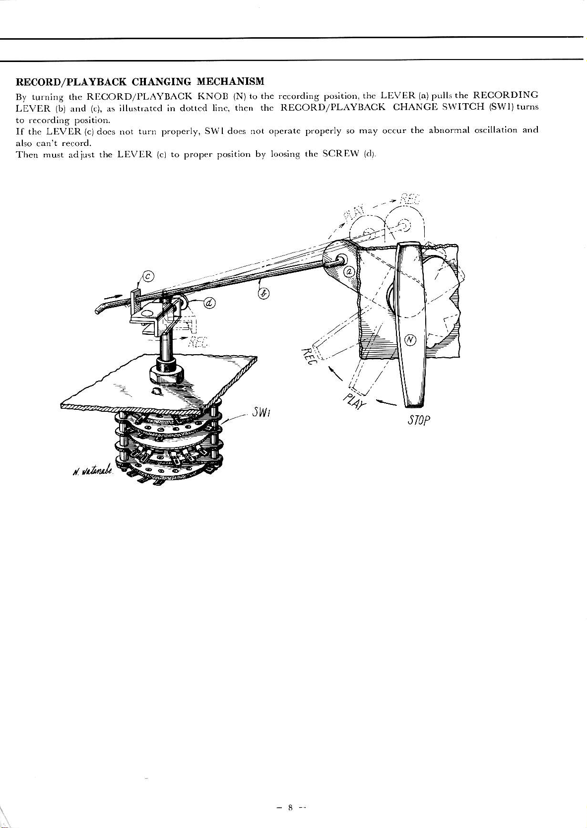
RDCORD/PLAYBACK CIIANGING
MECHANISM
By
turning the RLCORD/PLAYBACK
KNOB
(N)to
the
recording position, thr
LEVIiR
1a)pulls
the RECORDING
LEVER
(bi
and
(c),
as
;llushated in dotted l;nc,
then the RECORD/PLAYBACK
CHANGD SWITCH
(SWl)turns
to .ecording position.
If the LIVER
(c)do.s
not turn
Then
must
adjust
the LI.VIR
propc.ly.
SWI docs not operatc
prope.ly so may occu.
the abnormal oscillation
and
(cl
to proper position
by loos;ng thc SCREW
lcll.
.
r il.',
-
,z--\
Itz__\,/..r',
'l-a1'1';':
,
.'/...
(//
,,-^:,..
,/
\l/
/
..)._u.
.
,4)"
_
JWt
r
U
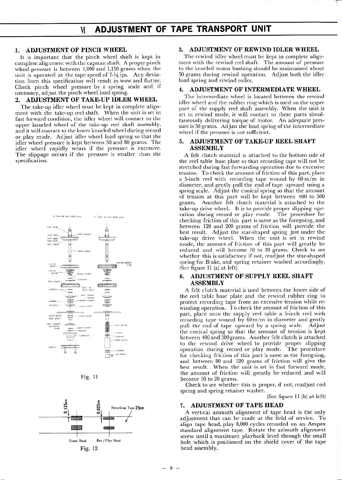
ADJUSTMENT
OF TAPE
TRANSPORT
UNIT
1. ADJUSTMENT OF
PINCII
WIIEEL
It is imporlant that the piich
wheel shaft i5
kept nr
complcte alignmentwith
the capstan shaft.
A properpinch
wheel
pressur€
is bctween
1.000 and I,150 grahs
whcn the
unit is ope.ated
at the tapc spccd of7-t6
ips. Any devia'
tion
from this specificalion
will result in wow and
flutter.
Check
I'in.h
wheel pre"su,. bv r
.1-.ring
'cale
at.d.
if
r,ecesar
y.
ad
ju"r
rhe pin, h
whpFl
load 5t.inB.
2, ADJUSTMENT OF
TAKE.UP IDLER WHEEL
The
take-up ;dlm wheel
must
be
kcpt in complete align-
ment ltith thc takc-up reel shaft.
Whcn the unit
is set in
fast forward condition,
thc idler
whe€l will contact to the
upper knu.led
wheel
of
the takc-up reel shaft
assembly.
and it
will
contact
to thc lower kn urled
whccl du.ing record
or
play modc. Adjust idlerwhccl
load spr;ngsoihatlhc
idler
wheel pressurc is kept between 50
and 80 grams.
The
;dler
qh..l
rapidlv
wear.
:f Ihf pre*u,.
b
Px,.ssi\c.
The slippage occurs
if thc prcssu.e
is smallef thaD the
3. ADJUSTMENT
OF
REWIND IDLER
WSEEL
The .c\rind
idler
whccl
must be kcpt in complete
align-
mcnt with thc rewi.d
reel
shaft. The amount
of
pressurc
to the k,,urlcd
motor bushing should be maintained
about
50 gfams during rewidd ope.ation. Adjust both thc idler
load spriog aDd
rewind roller.
4. ADJUSTMENT
OF
INTERMEDIATE WHEDL
Thc
intcrnediatc
wheel
is located between the
rewind
idler
whccl
and thc rubbe. ring vhich is uscd on the uppe.
part
of
the supply
reel shaft assembly. When
the unit is
sct in rewind mode, it will
contact
to thcsc parts sihul-
taneously deliverins torque of
motor. An
adequate
pres-
su.cis50grams. Adjust thc load sp.;ngofthc inrermed;ate
wheel if the
pressure is not sufrc;ent.
5. ADJUSTMENT OF TAKE-UP REEL SIIAI'T
ASSEMBLY
A felt clutch mat.rial is attachcd to the bottom sid€
ol
the
reel
table
basc plat€ so
that reco.ding tapc w;ll not bc
stretched during lhst forwafding operation due
to
excesivc
tension. To check the
amoudt
of friction of this part, plac€
a S'inch reel
with
fecordins
tape wound by 60m/m in
diameter, and gently pull the cnd of tapc upwarcl
using a
spring scale.
Adjust the
conical
sp.ing so that thc amount
of tension at this part will bc kept between
400 to
500
grams. Anoth€r felt
clutch
matoial ;s
attached
to
the
takc-up drive wheel. It is to pfovide proper slipping
opc-
ration
du.ing
record or play modc. The procedu.e
for
checkins friction of
this part
; same as
the foregoing, and
between 120 and 200 grams of frictioD
will provide the
best result.
Adjust the
star-shapcd
spring
jnst
under
the
takc-up dr;ve
whcel.
lvhen
the unit is
set
in rewind
mode,
the
amou.t
of f.iction of this part
will greatly
be
reduced and \viil become I0
to 20 grams.
Check
to scc
rvhether this is satisfactory ;f iot,
readjust the star-shaped
spring
fo. Bfakc, and spring rctainef
washed
accordingly.
lscc
fisure
ll
(al
at
lefo
6. ADJUSTMENT
OF SUPPLY REEL SIIAFT
ASSDMBLY
A felt clutch
matoial is uscd between
the love.
side
of
thc reel table base plate and
the .ewind rubbcr ring
to
protect reco.ding
tape from an excesive
tension \th;le re-
winding operation.
To
check
thc
amount
offriction of
this
pa.t, place onto thc supply reel
table
a 5-inch
rcel with
rcco.ding
tape wound by 60m/m in diameter and
gently
pulL thc cnd of tape upward by a spring
scale. Adjust
thc
conical sp.ing so
that thc amount of
tens;on ;s kept
bctwecn 400and500grams.
Anothc. fclt clutch is attached
to thc re\v;nd
drive
wheel to provide
proper
sl;pping
ope.atioD cluring
reco.d or play mod.. The procedure
for checkn)g
friction of this part is same as
the
foregoing,
and betwe€n 80 and
120
s.ams
of friction will give
the
best
result. Whcn
the
unit
js
set
;n fasi forward modc,
the
amount
of f.;ction will greatly be reduced and
will
become l0 to 20
grans.
Check
to
sce
whether this is proper, if not,
rcadjust coil
spring and spring r€tainer
washc..
{See
figure I I
(b)
at left)
7. ADJUSTMENT
OF TAPE HEAD
A
vertical azimuth
alignment of
tape head is the only
adjustment
that
can
be made at
the field
of service.
To
align tape head, play 8,000 cycles
recordcd on an AmP€x
standard alignment
tape. Rotate
th€
azimuth al;gnment
sc.ew
until a maximum
playback level through the small
hole which
is positioned on the shield cover
of the tape
head assembly.
-9-
..t,
;
Fig.
ll
R(/.Ly Hli
Fig.
12
:ir".
=..".".,..
 Loading...