

MANUFACTURING
NUMBERS:
9210116
9210117
9210119
9210121
9210123
9210214
VERTICAL CONTACT
TOASTER
Model VCT-2000 (Wide Mouth)
P/N 1010874 Rev. I 04/14
Owner’s Manual
VERTICAL CONTACT TOASTER
TABLE OF CONTENTS
Owner Information .....................................................2
General ......................................................................2
Warranty Information .................................................2
Service/Technical Assistance ....................................3
Specifications .............................................................5
Electrical Specifications .............................................5
Dimensions ................................................................5
Installation ...................................................................6
Unpacking ..................................................................6
Equipment Setup .......................................................6
Assembling the Unit ..................................................6
Operation .....................................................................8
Operating Instructions ...............................................8
Temperature Adjustments ..........................................8
Hi-Limit Reset Button ..............................................10
OWNER INFORMATION
General
Maintenance .............................................................. 11
Daily Maintenance ................................................... 11
Replacing the Black and Silver Release Sheet (Every
4–6 weeks) ..............................................................12
Replacing Belt Wraps (Every 3–6 months) .............12
Checking the Conveyor Belt Chains
(Every 3–6 Months) .................................................13
Replacing Roller Tensioners ....................................14
Troubleshooting .......................................................15
Replacement Parts ...................................................19
Wiring Diagram .........................................................25
Limited Warranty ......................................................28
Warranty Information
The VCT-2000 Vertical Contact Toaster is designed for
contact toasting of buns. The toaster design allows the
operator to place buns on both sides of the heated platen
at the same time. Buns are placed into the top of the
toaster and uniform, golden brown, warm buns are then
retrieved at the base of the toaster.
This manual provides the safety, installation, and
operating procedures for the Vertical Contact Toaster
Model VCT-2000. We recommend that all information
contained in this manual be read prior to installing and
operating the unit.
Your Vertical Contact Toaster Model VCT-2000 is
manufactured from the finest materials available and
assembled to Roundup’s strict quality standards. This
unit has been tested at the factory to ensure dependable trouble-free operation.
Please read the full text of the Limited Warranty in this
manual.
If the unit arrives damaged, contact the carrier immediately and file a damage claim with them. Save all
packing materials when filing a claim. Freight damage
claims are the responsibility of the purchaser and are
NOT covered under warranty.
The warranty does NOT extend to:
• Damages caused in shipment or damage as
result of improper use.
• Installation of electrical service.
• Normal maintenance as outlined in this manual.
• Malfunction resulting from improper maintenance.
• Damage caused by abuse or careless handling.
• Damage from moisture into electrical
components.
• Damage from tampering with, removal of, or
changing any preset control or safety device.
IMPORTANT! Keep these instructions for future reference.
If the unit changes ownership, be sure this manual accompanies the equipment.
2
P/N 1010874 Rev. I 04/14
VERTICAL CONTACT TOASTER
OWNER INFORMATION (continued)
Service/Technical Assistance
If you experience any problems with the installation
or operation of your unit, contact your local Roundup
Authorized Service Agency.
Fill in the information below and have it handy when
calling your Authorized Service Agency for assistance.
The serial number is on the specification plate located
on the rear of the unit.
Purchased From:
Date of Purchase:
Model No.:
Serial No.:
Mfg. No.:
Refer to the service agency directory included with your
unit.
Authorized Service Agency
Name:
Phone No.:
Address:
Use only genuine Roundup replacement parts in this
unit. Use of replacement parts other than those supplied by the manufacturer will void the warranty. Your
Authorized Service Agency has been factory trained
and has a complete supply of parts for this toaster.
You may also contact the factory at 1-877-392-7854
(toll Free in the U.S.) or 630-784-1000 if you have trouble locating the nearest Authorized Service Agency.
IMPORTANT
A.J. Antunes & Co. reserves the right to change specifications and product design
without notice. Such revisions do NOT entitle the buyer to corresponding changes,
improvements, additions, or replacements for previously purchased equipment.
P/N 1010874 Rev. I 04/14
3

VERTICAL CONTACT TOASTER
IMPORTANT SAFETY INFORMATION
In addition to the warnings and cautions in this manual,
use the following guidelines for safe operation of the
unit.
• Read all instructions before using equipment.
• For your safety, the equipment is furnished with
a properly grounded cord connector. Do NOT
attempt to defeat the grounded connector.
• Install or locate the equipment only for its intended use as described in this manual. Do NOT use
corrosive chemicals in this equipment.
• Do NOT operate this equipment if it has a damaged cord or plug, if it is not working properly, or
if it has been damaged or dropped.
• This equipment should be serviced by qualified
personnel only. Contact the nearest Authorized
Service Agency for adjustment or repair.
• Do NOT block or cover any openings on the unit.
• Do NOT immerse cord or plug in water.
• Keep cord away from heated surfaces.
• Do NOT allow cord to hang over edge of table or
counter.
• Bread may burn. Therefore toasters must
not be used near or below curtains or other
combustible walls and materials. Failure to
maintain safe operating distances may cause
discoloration or combustion.
• When installing the conveyor Belt Wrap, be
careful NOT to wrap it over the upper and
lower support rods or permanent damage to
belt will occur. Make sure the Belt Wrap is
positioned between the upper and lower
support rods.
• Make sure both ends of Belt Wrap are aligned
evenly before installing Belt Wrap Pin.
• Failure to use Release Sheets may result in
damage to the equipment and loss of
warranty coverage.
• Do NOT clean this appliance with a water jet.
• If supply cord is damaged, it must be replaced
by the manufacturer, its service agent, or a
similarly qualified person.
• All electrical connections must be in accordance with local electrical codes and any
other applicable codes.
The following warnings and cautions appear
throughout this manual and should be carefully
observed.
• Turn the power off, unplug the power cord,
and allow unit to cool down before performing
any service or maintenance.
• The toaster should be grounded according to
local electrical codes to prevent the possibility of electrical shock. It requires a grounded
receptacle with separate electrical lines protected by fuses or a circuit breaker of the
proper rating.
• WARNING, ELECTRICAL SHOCK HAZARD.
FAILURE TO FOLLOW THESE INSTRUCTIONS
COULD RESULT IN SERIOUS INJURY OR
DEATH.
- Electrical ground is required on this
appliance.
- Do NOT modify the power supply cord
plug. If it does not fit the outlet, have a
proper outlet installed by a qualified
electrician.
- Do NOT use an extension cord with this
appliance.
- Check with a qualified electrician if you
are unsure if the appliance is properly
grounded.
4
P/N 1010874 Rev. I 04/14
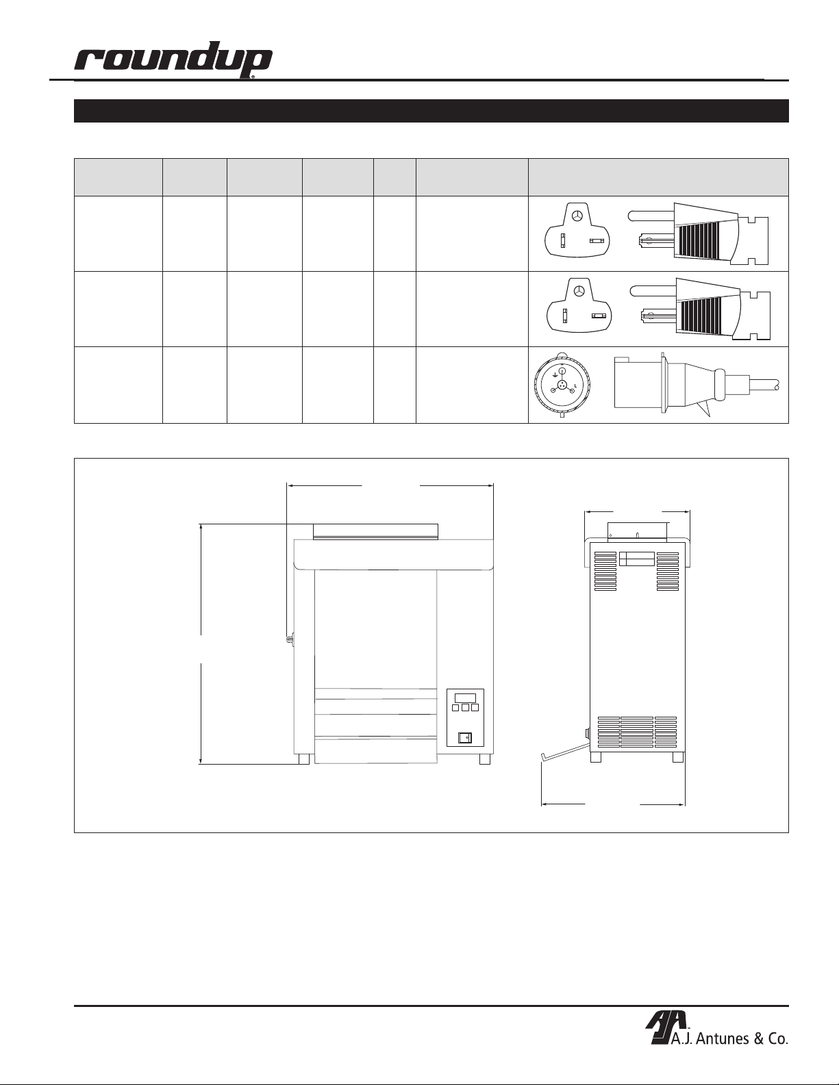
21 1/4"
(540 mm)
24 1/4"
(616 mm)
10 3/4"
(273 mm)
15 1/4"
(387 mm)
Electrical Specifications
VERTICAL CONTACT TOASTER
SPECIFICATIONS
Model &
Mfg. No.
VCT-2000
9210116
9210117
VCT-2000
9210119
9210121
9210123
VCT-2000
9210214
Dimensions
Voltage Watts Amps Hz.
208 3291 15.8 60
208 3291 15.8 60
220‒240 3019‒3593 13.7‒15 50
Plug
Description
6-20P, 20 Amp.,
250 VAC.,
Non–Locking
6-20P, 20 Amp.,
250 VAC.,
Non–Locking
IEC-309, 16 Amp.,
250 VAC.,
Pin & Sleeve
Plug Configuration
P/N 1010874 Rev. I 04/14
5
VERTICAL CONTACT TOASTER
INSTALLATION
Unpacking
1. Remove the unit and all packing materials from
shipping carton.
2. Open the included large box. It should contain
the following:
• Bun Chute (Figure 1) (some models only).
• Bun Feeder (Figure 1) (some models only).
• Two Release Sheets (Figure 1).
• Owner’s Manual
• Maintenance Card (some models only).
• Authorized Service Agency Directory.
3. Remove all shipping tape and protective
coverings from the unit and parts.
NOTE: If any parts are missing or damaged,
contact Antunes Technical Service IMMEDIATELY
at 1-877-392-7854 (toll free in the U.S.) or 630-784-
1000.
Equipment Setup
Before placing the toaster into service, pay attention to
the following guidelines:
CAUTION
Failure to use Release Sheets may result in
damage to the unit and loss of warranty coverage.
CAUTION
Bread may burn. Therefore toasters must not be
used near or below curtains or other combustible
walls and materials. Failure to maintain safe
operating distances may cause discoloration or
combustion.
WARNING
ELECTRICAL SHOCK HAZARD. FAILURE TO
FOLLOW THE INSTRUCTIONS IN THIS MANUAL
COULD RESULT IN SERIOUS INJURY OR DEATH.
• Electrical ground is required on this appliance.
• Do NOT modify the power supply cord plug. If
it does not fit the outlet, have a proper outlet
installed by a qualified electrician.
• Do NOT use an extension cord with this appliance.
• Make sure power to the unit is off and the toaster
is at room temperature.
• Do NOT block or cover any openings on the unit.
• Do NOT immerse cord or plug in water.
• Keep cord away from heated surfaces.
• Do NOT allow cord to hang over edge of table or
counter.
• Connect the unit to the proper power supply.
Refer to the specification plate for the proper
voltage.
Assembling the Unit
NOTE: The factory has pre-installed a Release
Sheet over the Platen (Figure 1). Verify that it is
properly in place before proceeding.
1. Remove Bun Chute and Bun Feeder from the box
and install (Figure 1).
NOTE: Make sure Heat Shield is activating the
Conveyor Safety Interlock Switch (Figure 1). The
conveyors will not rotate unless the Heat Shield is in
place and Conveyor Safety Interlock Switch is
activated.
• The toaster should be grounded according to
local electrical codes to prevent the possibility of electrical shock. It requires a grounded
receptacle with separate electrical lines
protected by fuses or a circuit breaker of the
proper rating.
• Check with a qualified electrician if you are
unsure if the appliance is properly grounded.
CAUTION
All electrical connections must be in accordance
with local electrical codes and any other applicable codes.
6
P/N 1010874 Rev. I 04/14
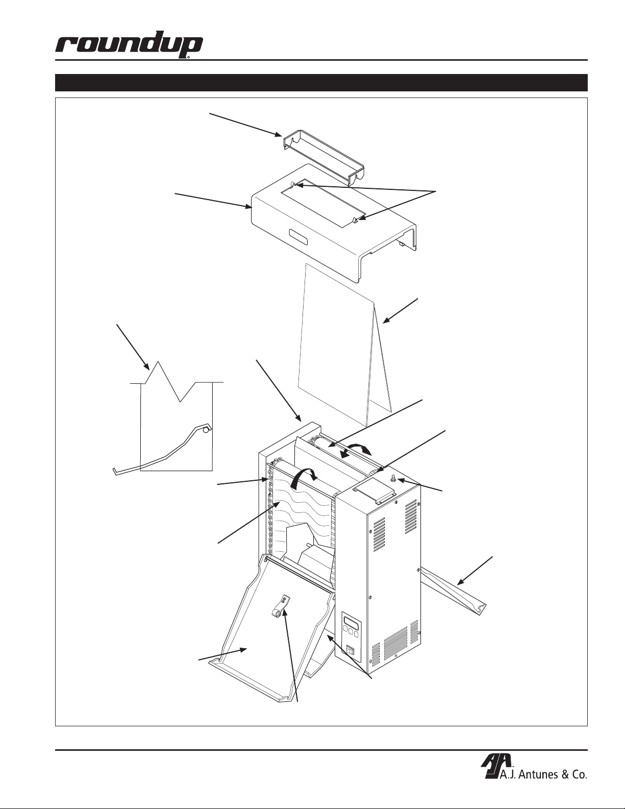
Bun Feeder
(some models only)
Heat Shield
VERTICAL CONTACT TOASTER
INSTALLATION (continued)
Release
Sheet
Retainer
Clips
Bun Chute Assembly
connected over the
bottom rear support rod
(some models only)
Front
Conveyor
Belt Chain
Front Belt
Wrap
Release
Sheet
Platen
Rear Belt
Wrap
Rear
Conveyor
Belt Chain
Conveyor
Safety
Interlock
Switch
Rear Conveyor
Cover Assembly
(with Roller
Tensioner)
Front Conveyor
Cover Assembly
P/N 1010874 Rev. I 04/14
Bun Chute
Roller Tensioner
Figure 1. VCT-2000 Toaster
7
VERTICAL CONTACT TOASTER
1
2
4
5
1 = 1/2"(12.7mm)
2 = 5/8"(15.9mm)
3 = 11/16"(17.5mm)
6 = 7/8"(22.2mm)
THICKNESS
THICKNESS
1
2
3
4
6
6
5
4 = 3/4"(19.1mm)
5 = 13/16"(20.6mm)
3
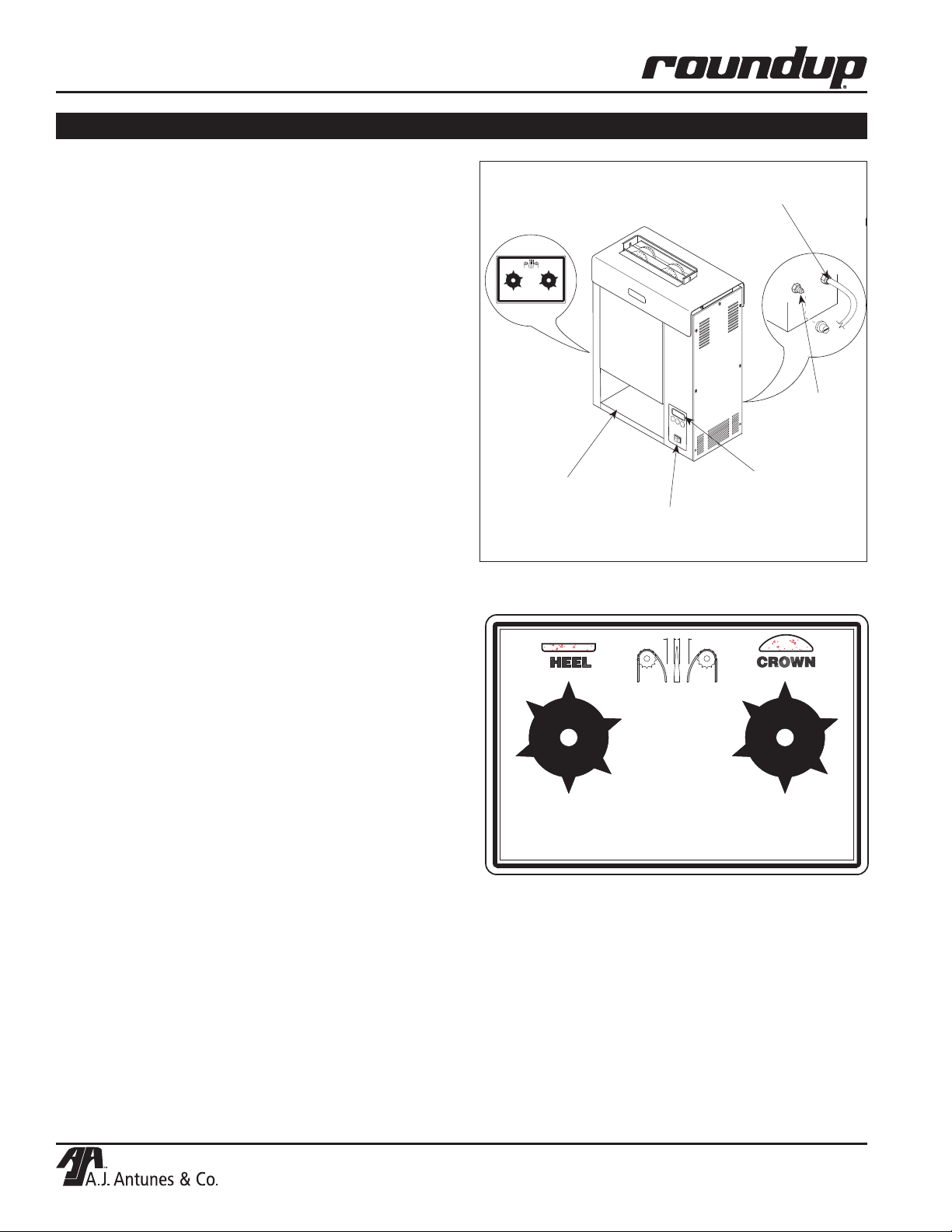
OPERATION
Operating Instructions
1. Set the Bun Thickness Adjustment Controls
(Figures 2 & 3) to desired setting.
NOTE: Recommended settings are 2 for Heel and
F for Crown.
2. Turn the power on and allow the toaster to
warm-up for 30 minutes before proceeding.
NOTE: The temperature display (Figure 2) will flash
“LO” until the toaster reaches its preset operating
temperature. When the toaster approaches the preset temperature of 600°F (315°C), “USE” appears
in the temperature display and the unit is ready to
toast buns. If “USE” does not appear in the window
after warm-up period of approximately 30 minutes,
contact your Authorized Service Agency.
3. Drop Crowns and Heels into the slot (Figure
2). Cut sides of heel and crown must face each
other.
Bun Thickness
Adjustment Control
(See Figures 3 & 4)
Bun Landing Area
Power
Switch
Power
Cord
Hi-Limit
Reset
Temperature
Controls
& Temperature
Display
4. Toasted buns will drop into the Bun Landing Area
(Figure 2) in approximately 10 seconds.
5. Test at least four buns before putting the toaster
into service.
6. Turn the power off when finished toasting for the
day and proceed with the Daily Cleaning as outlined in the Maintenance section of this manual.
Temperature Adjustments
The VCT-2000 uses a Platen Heater and two Auxiliary
Air Heaters. The Platen Heater consists of a heating
element built into the Platen to toast the cut side of the
bun. The two Auxiliary Heaters assist in providing
additional heat to the buns. The first Auxiliary Air
Heater is located between the conveyor in the front
of the toaster. The second Auxiliary Heater is located
between the conveyor at the rear of the unit.
RECOMMENDED TEMPERATURES
Recommended temperature setting for the Platen
Heater is 600°F (315°C).
Figure 2. VCT-2000 Toaster
THICKNESS
3
2
4
1
5
1 = 5/8" (16mm)
6
2 = 3/4" (19mm)
3 = 13/16" (21mm)
4 = 7/8" (22mm)
5 = 15/16" (24mm)
6 = 1" (25mm)
THICKNESS
E
D
A = 3/4" (19mm)
B = 7/8" (22mm)
C = 15/16" (24mm)
D = 1" (25mm)
E = 1 1/16" (27mm)
F = 1 1/8" (29mm)
F
B
C
Figure 3. Bun Thickness Adjustment Controls
A
Recommended temperature setting for the Auxiliary Air
Heaters is 400°F (204°C).
NOTE: The toaster is tested and shipped with the
heaters set at the above recommended temperatures.
8
P/N 1010874 Rev. I 04/14
VERTICAL CONTACT TOASTER
TEMP
UP
TEMP
DOWN
TEMP
SCALE
˚F
˚C
POWER
TEMP
UP
TEMP
DOWN
TEMP
SCALE
˚F
˚C
POWER
SP - P
600
TEMP
UP
TEMP
DOWN
TEMP
SCALE
˚F
˚C
POWER
TEMP
UP
TEMP
DOWN
TEMP
SCALE
˚F
˚C
POWER
400
SP - A
TEMP
UP
TEMP
DOWN
TEMP
SCALE
°F
°C
POWER
LO
USE
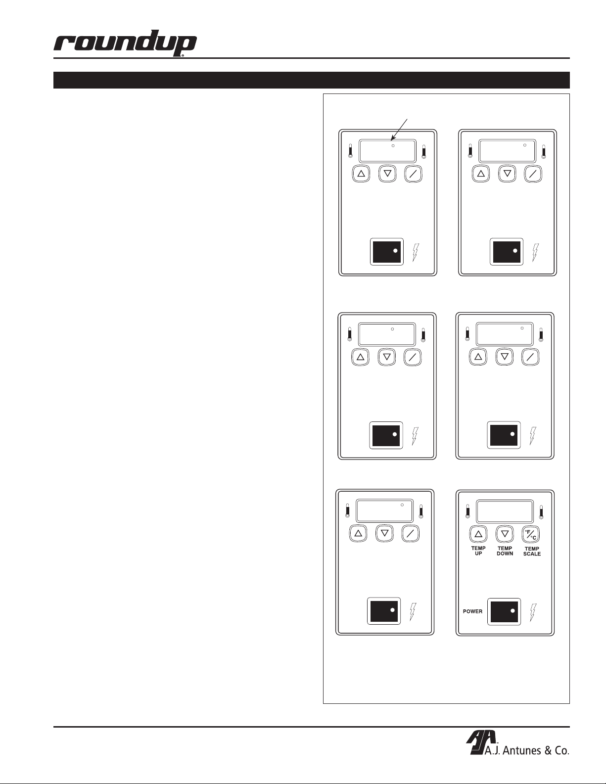
OPERATION (continued)
TEMPERATURE CONTROL PANEL
NOTE: The term “setpoint temperature” refers to
the desired temperature setting.
To display the actual Platen temperature—providing it
is over 440°F (227°C)—press the TEMP UP button.
To display the actual Auxiliary Air Heater temperature—
providing it is over 360°F (182°C)—press the TEMP
DOWN button.
To switch the temperature display between Fahrenheit
(°F) and Celsius (°C), press and hold the TEMP
SCALE button for 5 seconds.
PLATEN HEATER TEMPERATURE ADJUSTMENT
1. Turn the power on and wait for the Temperature
Display to finish the power-up sequence (Figure 4).
2. Press and hold the TEMP UP and TEMP DOWN
buttons for more than 1 second until the display
flashes the Platen setpoint temperature, then
release.
3. Press the TEMP UP button to raise the setpoint
temperature or press the TEMP DOWN button to
lower the setpoint temperature.
NOTE: The maximum Platen setpoint temperature
is 600°F (315°C). If no change in temperature is
made within 5 seconds, the display reverts back to
the previous setpoint.
“Heat On” LED will blink on/off during warm-up and when either
platen or auxiliary air heaters are calling for heat.
1. “SP-P” (Setpoint Platen)
is displayed.
2. Current Platen setpoint
temperature setting is shown.
4. Release the button when the desired setpoint is
displayed.
AUXILIARY AIR HEATER TEMPERATURE ADJUSTMENT
1. Turn the power on and wait for Temperature Display
to finish the power-up sequence (Figure 4).
2. Press and hold the TEMP UP and TEMP SCALE
buttons for more than 1 second until the display
flashes the setpoint temperature, then release.
3. Press the TEMP UP button to raise the setpoint
temperature or press the TEMP DOWN button to
lower the setpoint temperature.
NOTE: The maximum Auxiliary Air Heater setpoint
temperature is 400°F (204°C).
4. Release the button when the desired setpoint is
displayed.
NOTE: If no change in temperature is made within
5 seconds, the display reverts back to the previous
setpoint.
P/N 1010874 Rev. I 04/14
3. “SP-A” (Setpoint Auxiliary)
is displayed.
5. “LO” is displayed until
Platen temperature rises
above 550°F (288°C).
Figure 4. Temperature Power-Up Sequence
9
4. Current Auxiliary Air setpoint
temperature is shown.
6. “USE” is displayed when
Platen setpoint temperature*
is reached.
* Platen setpoint temperature
must be between 460°F and
600°F (238°C and 315°C).
 Loading...