

Page 1
Io X3
Capture, Display, Convert
Installation and Operation Manual
Version 16.2
Published January 24, 2022
Page 2
Notices
Trademarks
Copyright
AJA® and Because it matters.® are registered trademarks of AJA Video Systems, Inc.
for use with most AJA products. AJA™ is a trademark of AJA Video Systems, Inc. for
use with recorder, router, software and camera products. Because it matters.™ is a
trademark of AJA Video Systems, Inc. for use with camera products.
Corvid Ultra®, lo®, Ki Pro®, KONA®, KUMO®, ROI® and T-Tap® are registered trademarks of
AJA Video Systems, Inc.
AJA Control Room™, KiStor™, Science of the Beautiful™, TruScale™, V2Analog™ and
V2Digital™ are trademarks of AJA Video Systems, Inc.
All other trademarks are the property of their respective owners.
Copyright © 2022 AJA Video Systems, Inc. All rights reserved. All information in
this manual is subject to change without notice. No part of the document may be
reproduced or transmitted in any form, or by any means, electronic or mechanical,
including photocopying or recording, without the express written permission of AJA
Video Systems, Inc.
Contacting AJA Support
When calling for support, have all information at hand prior to calling. To contact AJA
for sales or support, use any of the following methods:
Telephone +1.530.271.3190
FAX +1.530.271.3140
Web https://www.aja.com
Support Email [email protected]
Sales Email [email protected]
Io X3 Capture, Display, Convert v16.2 2 www.aja.com
Page 3

Contents
Notices . . . . . . . . . . . . . . . . . . . . . . . . . . . . . . . . . . . . . . 2
Trademarks . . . . . . . . . . . . . . . . . . . . . . . . . . . . . . . . . . . . . . . . . . . 2
Copyright . . . . . . . . . . . . . . . . . . . . . . . . . . . . . . . . . . . . . . . . . . . . 2
Contacting AJA Support . . . . . . . . . . . . . . . . . . . . . . . . . . . . . . . . . . . 2
Chapter 1 – Introduction . . . . . . . . . . . . . . . . . . . . . . . . . . . 5
Overview. . . . . . . . . . . . . . . . . . . . . . . . . . . . . . . . . . . . . . . . . . . . .5
Features. . . . . . . . . . . . . . . . . . . . . . . . . . . . . . . . . . . . . . . . . . . .5
Video Formats. . . . . . . . . . . . . . . . . . . . . . . . . . . . . . . . . . . . . . . .6
Io X3 Audio . . . . . . . . . . . . . . . . . . . . . . . . . . . . . . . . . . . . . . . . . .6
AJA Software & Utilities . . . . . . . . . . . . . . . . . . . . . . . . . . . . . . . . . .6
System Requirements. . . . . . . . . . . . . . . . . . . . . . . . . . . . . . . . . . . . .7
What’s In The Box? . . . . . . . . . . . . . . . . . . . . . . . . . . . . . . . . . . . . . . .7
In This Manual . . . . . . . . . . . . . . . . . . . . . . . . . . . . . . . . . . . . . . . . . 7
Chapter 2 – Installation . . . . . . . . . . . . . . . . . . . . . . . . . . . . 8
Installation Overview . . . . . . . . . . . . . . . . . . . . . . . . . . . . . . . . . . . . . 8
Cable Connections . . . . . . . . . . . . . . . . . . . . . . . . . . . . . . . . . . . . . 8
Connector Descriptions. . . . . . . . . . . . . . . . . . . . . . . . . . . . . . . . . . 8
Installing Software . . . . . . . . . . . . . . . . . . . . . . . . . . . . . . . . . . . . . 10
macOS Installations . . . . . . . . . . . . . . . . . . . . . . . . . . . . . . . . . . . 10
Chapter 3 – Io X3 Operation . . . . . . . . . . . . . . . . . . . . . . . . 11
Front Panel Operation . . . . . . . . . . . . . . . . . . . . . . . . . . . . . . . . . . . 11
Monitor Output and Gain Control . . . . . . . . . . . . . . . . . . . . . . . . . . 11
Audio Level Meters . . . . . . . . . . . . . . . . . . . . . . . . . . . . . . . . . . . . 11
Status LED . . . . . . . . . . . . . . . . . . . . . . . . . . . . . . . . . . . . . . . . . 12
AJA Control Panel Overview . . . . . . . . . . . . . . . . . . . . . . . . . . . . . . . 12
AJA Control Panel Operating Modes. . . . . . . . . . . . . . . . . . . . . . . . . 12
AJA Control Panel User Interface . . . . . . . . . . . . . . . . . . . . . . . . . . . 12
Controlling Application . . . . . . . . . . . . . . . . . . . . . . . . . . . . . . . . . 15
Presets. . . . . . . . . . . . . . . . . . . . . . . . . . . . . . . . . . . . . . . . . . . . 16
Default Preferences . . . . . . . . . . . . . . . . . . . . . . . . . . . . . . . . . . . 16
Function Screens . . . . . . . . . . . . . . . . . . . . . . . . . . . . . . . . . . . . . 17
Io X3 Audio Monitoring. . . . . . . . . . . . . . . . . . . . . . . . . . . . . . . . . . . 18
AJA Control Panel Function Screens . . . . . . . . . . . . . . . . . . . . . . . . . . 20
Control Screen. . . . . . . . . . . . . . . . . . . . . . . . . . . . . . . . . . . . . . . 20
Format Screen . . . . . . . . . . . . . . . . . . . . . . . . . . . . . . . . . . . . . . . 22
Input Select Screen. . . . . . . . . . . . . . . . . . . . . . . . . . . . . . . . . . . . 23
SDI Output Screen . . . . . . . . . . . . . . . . . . . . . . . . . . . . . . . . . . . . 25
HDMI Screen . . . . . . . . . . . . . . . . . . . . . . . . . . . . . . . . . . . . . . . . 27
HDR Screens . . . . . . . . . . . . . . . . . . . . . . . . . . . . . . . . . . . . . . . . 29
Video Setup Screen . . . . . . . . . . . . . . . . . . . . . . . . . . . . . . . . . . . 32
Audio Setup Screen . . . . . . . . . . . . . . . . . . . . . . . . . . . . . . . . . . . 33
Audio Mixer Screens . . . . . . . . . . . . . . . . . . . . . . . . . . . . . . . . . . . 34
Audio Mixer Capture Monitor Mode Screen . . . . . . . . . . . . . . . . . . . . 36
Audio Mixer Playback Monitor Mode Screen . . . . . . . . . . . . . . . . . . . 37
DS Keyer Screen . . . . . . . . . . . . . . . . . . . . . . . . . . . . . . . . . . . . . . 39
LUT Screen . . . . . . . . . . . . . . . . . . . . . . . . . . . . . . . . . . . . . . . . . 41
Timecode Screen . . . . . . . . . . . . . . . . . . . . . . . . . . . . . . . . . . . . . 44
Presets Screen . . . . . . . . . . . . . . . . . . . . . . . . . . . . . . . . . . . . . . . 45
Firmware Screen . . . . . . . . . . . . . . . . . . . . . . . . . . . . . . . . . . . . . 47
Info Screen . . . . . . . . . . . . . . . . . . . . . . . . . . . . . . . . . . . . . . . . . 48
Appendix A – Specications . . . . . . . . . . . . . . . . . . . . . . . . 49
Io X3 Tech Specs . . . . . . . . . . . . . . . . . . . . . . . . . . . . . . . . . . . . . . . 49
Appendix B – Safety and Compliance . . . . . . . . . . . . . . . . . . 52
Io X3 Capture, Display, Convert v16.2 3 www.aja.com
Page 4

Warranty and Liability Information . . . . . . . . . . . . . . . . . . . .60
Index. . . . . . . . . . . . . . . . . . . . . . . . . . . . . . . . . . . . . . .61
Io X3 Capture, Display, Convert v16.2 4 www.aja.com
Page 5
Chapter 1 – Introduction
Overview
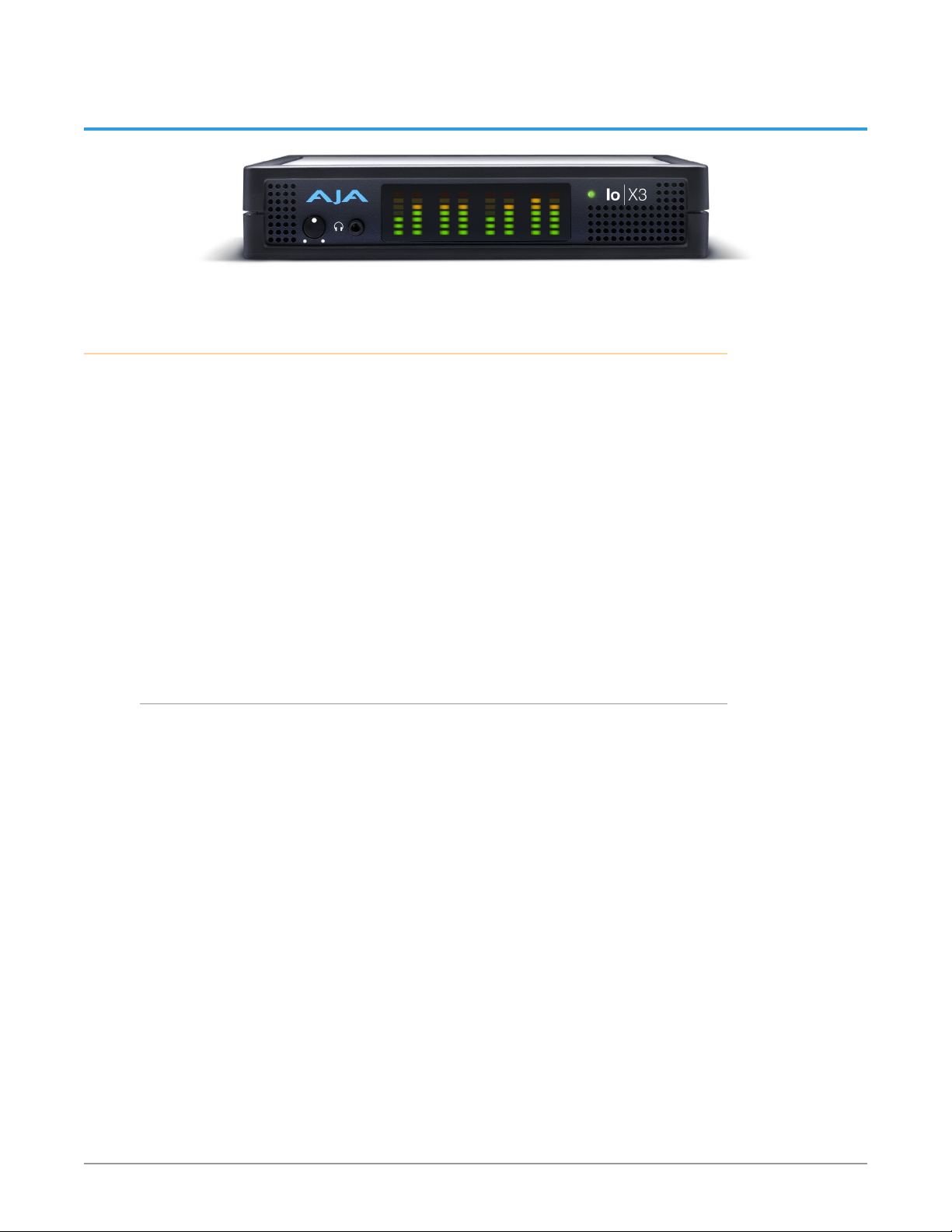
AJA Io X3 is perfect for high quality HDR or SDR work with HD/2K signals or files
up to 60p. Connecting with a single Thunderbolt 3 cable and providing a second
Thunderbolt connector for flexibility, Io X3's compact and quiet form factor is
ideal for on set, in the studio, at an event or in the edit suite.
For Editorial, VFX, Grading, Mastering and Graphic workflows, Io X3 enables input,
output and monitoring for both single and dual-link SDI sources and destinations,
plus a dedicated reference connector and RS 422 serial interface.
For Audio Workflows Io X3 supports 16 channels of embedded audio per SDI
channel, 8 channels of embedded audio per HDMI channel, 8 channels of Analog
Audio Input or Output (or 4 in plus 4 out), stereo headphone connector and
discrete LTC Input and Output connectors.
For Switching and Streaming workflows Io X3 simultaneously provides up to 4
channels for Input, and a single channel for Output, plus a MultiView feature that
enables viewing up to four SDI input sources via HDMI out (when the application
Program Out is not assigned).
Features
• Two Thunderbolt 3 ports
• Four bidirectional SDI BNCs configurable for up to four inputs, or four outputs,
or two inputs and two outputs.
• Dual Link I/O for 1.5G-SDI and 3G-SDI (2 x BNC)
• Quad Link I/O for 1.5G-SDI, 3G-SDI (4 x BNC)
• HDMI 1.4b (using HDMI 2.0 implementation)
• VPID signaling for SDR/HDR Transfer Characteristics, Colorimetry and
Luminance via SDI
• PQ, HLG and HDR10 Supported
• MultiView feature, able to display up to four Io X3 SDI video inputs on a single
HDMI UltraHD capable output monitor.
• Eight-channel Embedded HDMI audio
• Choice of Eight-Channel In, Eight-Channel Out, or Four-Channel In/Out analog
audio (DB25 cable, Line Level)
• Front panel LED VU meters and Headphone output w/level control
• Dedicated Reference In BNC
• Individual LTC Input and Output BNCs
• RS-422 control via 9-pin
• Rugged Chassis, Small Size
• 12V DC, 4-pin XLR Power (AC adapter included)
Io X3 Capture, Display, Convert v16.2 5 www.aja.com
Page 6

Video Formats
For a list of supported video formats, see "Appendix A Specifications" on page 49.
Io X3 Audio
Io X3 provides up to 16 channels of SDI embedded audio, and up to eight
channels of embedded HDMI audio. Eight channels of analog audio I/O is
supported via a DB25 industry standard Tascam style audio breakout cable. The
eight analog audio channels can be configured as either Ch 1-8 input, Ch 1-8
output, Ch1-4 input with Ch 5-8 output or, Ch 1-4 output with Ch 5-8 input.
AJA Software & Utilities
Io X3 operates with AJA's Desktop software package, developed for powerful
integrated video/audio capture, editing, and production with a variety of 3rdparty software. AJA software is distributed as a unified package which includes all
the software, firmware, plugins, and utility programs for the Io X3, as well as AJA’s
Io, KONA, and T-TAP products.
Two retail packages are available, one for Mac and one for Windows.
Mac and Windows Packages
These packages include:
Drivers
AJA device drivers for tightly integrated hardware/software operation.
AJA Control Panel
The Control Panel provides:
• Source selection and control of your AJA hardware.
• A block diagram to show visually what routing and processing is being
performed.
AJA Control Room
Control Room is a cross-platform software application for capture, playback and
output with AJA products.
AJA System Test
AJA System Test is a utility for measuring system performance. The application
includes:
• System Disk Test
• AJA Device Test
• System Report
The application tests Read and Write, Capture and Playback speeds tests in both
Megabytes per second and Frames per second. The disk speed tests differ from
standard disk I/O performance applications in that they specifically test the
system under conditions typically encountered with video capture, playback, and
editing.
NOTE: Theoretically the best test is to fill your storage disk to 80% and then test capture
at the highest data rate you will use.
Io X3 Capture, Display, Convert v16.2 6 www.aja.com
Page 7

3rd-Party Plugins
Plugins for popular 3rd-party Professional Video Applications from Adobe, Avid,
Apple, OBS, Telestream, and others.
System Requirements
NOTE: On macOS, the Io X3 supports Apple’s M1 chip, as well as earlier Intel processors.
AJA Video recommends that your system meet minimum hardware and software
requirements to achieve a satisfactory level of performance. Updates to system
requirements are subject to change.
See the Release Notes for your AJA Card or Device, available on the AJA website
and also installed with the software package, for minimum and recommended
system requirements including OS, CPU, RAM, and GPU.
NOTE: Also see Software Vendor system requirements for GPU recommendations and
additional hardware requirements and recommendations.
NOTE: For large scale installations with shared storage, IP, or for very high performance
requirements, AJA recommends consultation with an experienced system
integrator. A consultant will be able to assist with many important variables.
What’s In The Box?
As you unpack the shipping box, carefully examine the contents. Ensure you
received everything and that nothing was damaged during shipment.
If you find any damage, immediately notify the shipping service and supply them
with a complete description of the damage, and contact your dealer or distributor
for details on how to have your Io X3 repaired or replaced.
Save packing materials and the shipping box for future use should you need to
transport your system or return it for service.
Inside the box you’ll find the following components:
• Io X3
• 12V power adapter and power cord
In This Manual
Chapter 1 - Introduces the product briefly, listing features and system
requirements.
Chapter 2 - Provides complete instructions for installing and configuring the
product.
Chapter 3 - Discusses operational aspects and how to work with 3rd-party
software.
Appendix A - Presents a list of technical specifications for the product.
Appendix B - Provides important Safety and Compliance information.
Io X3 Capture, Display, Convert v16.2 7 www.aja.com
Page 8
Ports (2)
Chapter 2 – Installation
Installation Overview
1. If not previously installed on your Thunderbolt equipped computer, ensure
that appropriate third party application software is installed as detailed in
its user documentation.
2. Download and install the latest Io X3 software from:
https://www.aja.com/en/support/downloads
3. Connect your Io X3 to your computer using an appropriate Thunderbolt
cable.
4. Connect the video and audio inputs and outputs.
5. Power up the unit (AC supply or battery). The Io X3 will startup
automatically.
6. AJA recommends that you now run AJA Control Panel, as this allows you to
verify that the installation has completed successfully.
NOTE: AJA Control Panel will prompt you to update firmware (if the new software
package contained a firmware update for your AJA device).
Cable Connections
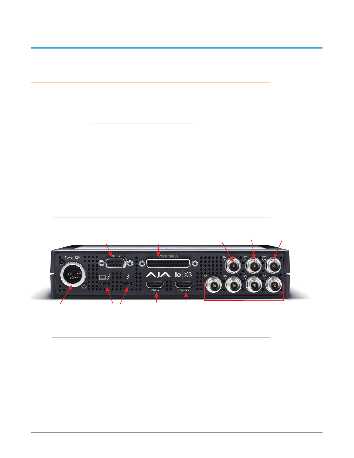
Figure 1. Io X3 Connectors
DB-9F RS-422
Machine Control
4-Pin XLR
DC Power Input
Thunderbolt 3
Connector Descriptions
Thunderbolt 3
The Io X3 provides the third-generation Thunderbolt 3 (USB-C) ports to support
increased bandwidth between host computer and I/O device. Two ports are
provided for daisy-chained network configurations.
The left port with the special logo is meant to identify the downstream
Thunderbolt 3 port. The port on the right with the standard logo is meant to
indicate the upstream port that is to be connected to the host computer. Despite
a regulatory need to label one of these ports as downstream, the Io X3 actually
has a fully symetric Thunderbolt implementation. Either port can be used for
either an upstream or downstream connection.
Balanced Audio In/Out
DB-25F (8-Ch)
HDMI
Input
HDMI
Output
Reference
Input
3G/HD/SD-SDI BNCs (4)
LTC Input
Bidirectional
LTC Output
Io X3 Capture, Display, Convert v16.2 8 www.aja.com
Page 9

NOTE: Io X3 does not support host computer charging through the standard logo
'upstream' Thunderbolt port.
Bi-directional SDI I/O
Four bidirectional BNC connectors can be configured in a variety of ways via the
AJA Control Panel, including:
• Two HD/SD inputs (SDI 1 and SDI 2) and two outputs (SDI 3 and SDI 4)
• Four HD/SD inputs (SDI 1, SDI 2, SDI 3, SDI 4)
NOTE: Some third-party applications (examples: OBS Studio, Wirecast, Vmix) may
support other input/output configurations. Please see the relevant AJA Quick
Start Guide document for the application you are using.
HDMI Input and Output
Two HDMI connectors provide input and output of HDMI video and multichannel embedded audio.
• HDMI 1.4b input and output (using HDMI 2.0 implementation) supporting
resolutions at up to 60p (4:2:2), 10-bit
• Supports two or eight channel HDMI audio input and output
HDMI output also supports:
• HDR 10 Support - HDR Infoframe metadata, compatible with HDMI 2.0a/CTA-
861.3
• HLG Support - compatible with HDMI 2.0b/CTA-861-G
NOTE: HDCP is not supported on either input or output. HDMI output does not have
HDCP, and input sources having HDCP are not supported.
The HDMI input is designed to support long cable runs—up to 100 ft. when using
22 or 24AWG HDMI cable, or up to 50 ft. using 28 or 30AWG HDMI cable. The
HDMI output supports standard HDMI cables only.
RS-422 Machine Control
A female DB-9 connector provides connection for VTRs, camcorders, disk media
servers, and other devices using RS-422 SMPTE (Sony) protocol.
Reference Video
A dedicatec BNC connector provides reference Input. Supplying a reference signal
to the Reference input allows you to synchronize Io X3 outputs to your house
analog reference video signal (or black burst). When connecting a reference video
source, the locking signal should be the same as the input format. It is possible in
some circumstances to use an alternate format video signal as long as the basic
frame rate is compatible.
LTC Input and Output
Two BNC connectors provide dedicated LTC input and output.
Io X3 Capture, Display, Convert v16.2 9 www.aja.com
Page 10

Balanced Analog Audio Input and Output
A 25-pin connector provides 8-channel balanced analog audio, 24-bit 48kHz
sample rate D/A and A/D. This will require an industry standard 8x XLR on DB-25
breakout cable (not supplied). The eight analog audio channels can be configured
four different ways:
• Ch 1-8 Output
• Ch 1-4 Input and Ch 5-8 Output (default)
• Ch 1-4 Output and Ch 5-8 Input
• Ch 1-8 Input
12V Power Connector
A standard 4-pin XLR type connector is provided for either battery or line source
power using the supplied AC power adapter.
Installing Software
NOTE: If your computer has previously had another video capture or multimedia device
installed, ensure you uninstall any related software before installing Io X3. This
will prevent any hardware or software conflicts.
Before installing the software package, ensure that your capture/editing
application is installed as detailed in its user documentation. Before using Io X3
an NLE application, it is best practice to have installed and run the software at
least once on your workstation. Next, install the AJA software package.
If at a later date you add any Io X3 supported applications that require drivers,
you must run the AJA install program again to install them.
macOS Installations
macOS High Sierra (10.13), macOS Mojave (10.14), macOS Catalina (10.15), macOS
Big Sur (11.x) and macOS Monterey (12.x) all have security requirements that may
present dialogs during installation. Please refer to the Release Notes for guidance.
Io X3 Capture, Display, Convert v16.2 10 www.aja.com
Page 11
Chapter 3 – Io X3 Operation
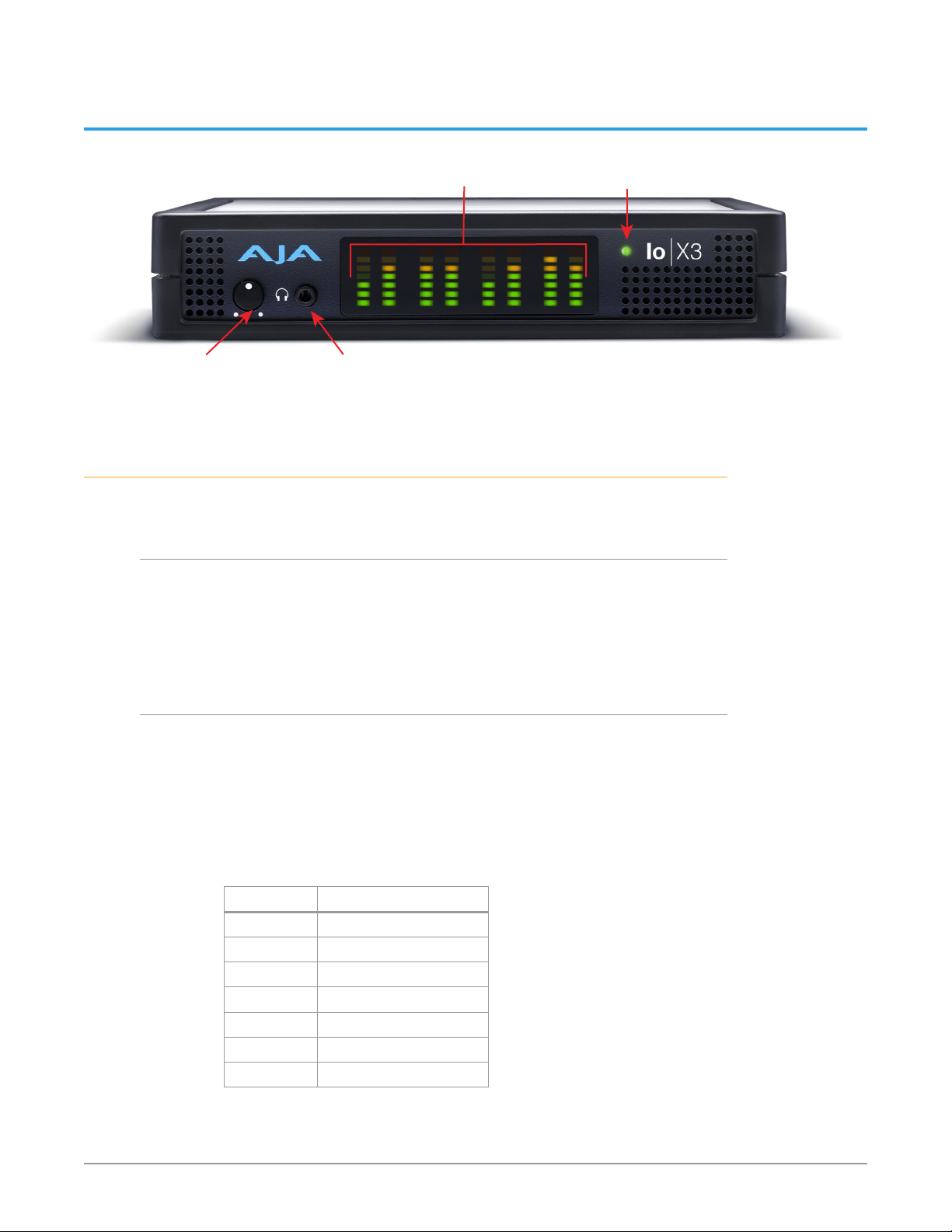
Monitor
Gain Control
Monitor Output
Connector 1/8 in. TRS
Front Panel Operation
The Io X3 front panel has the following controls and indicators:
Monitor Output and Gain Control
A 1/8 inch TRS connector is available for monitoring two channels of audio,
selectable in channel pairs using the Control Panel application. Typically used
with a pair of headphones.
The Monitor Gain knob on the left adjusts the monitor output level. Pushing in
the knob extends it (for adjustment) or recesses it (to prevent accidental changes).
Audio Level
Meters (8)
Status
LED
Audio Level Meters
The Audio Level Meters in the center of the front panel indicate:
• During Capture - The first 8 channels of the audio source selected (SDI, HDMI,
Analog).
• During Playback - The sum of whatever sources are being played out via
the AJA hardware; i.e. NLE timeline and mix of host system audio output (if
applicable).
The meter's LEDs are colored to indicate the amount below 0dBfs when averaged
over a one millisecond time interval:
dBfs LED Color and Location
-2 db Red LED 1 (top)
-12 db Yellow LED 2
-20 db Yellow LED 1
-30 db Green LED 4
-40 db Green LED 3
-50 db Green LED 2
-60 db Green LED 1 (bottom)
NOTE: These audio level meters are for guidance only. Third-party audio metering
should be employed when doing critical audio editing and mixing.
Io X3 Capture, Display, Convert v16.2 11 www.aja.com
Page 12

Status LED
This LED indicates the current connection status of your Io X3.
• OFF: No power detected
• AMBER SOLID: Power is on but Thunderbolt is not live (e.g. Thunderbolt ports
disabled in host, BIOS settings)
• AMBER BLINKING: Thunderbolt is awake but no PCIe connection to host (e.g.
device hasn’t been whitelisted by the Thunderbolt software running on host)
• GREEN BLINKING: Thunderbolt is awake, PCIe is connected, but device doesn’t
see the NTV2 Driver (This shows up on Windows where the AJA driver has
been restricted from talking to peripherals – security setting error, or because
the AJA software is not installed on the host)
• GREEN SOLID: Thunderbolt is communicating properly
AJA Control Panel Overview
The AJA Control Panel is a software application that provides a simple visual
showing how the Io X3 hardware is currently configured and allows you to make
changes. You can change signal input and output parameters and define the
video processing that will be performed.
The AJA software installer automatically installs the Control Panel application on
your computer. You’ll find the AJA Control Panel application in your Applications
folder.
AJA Control Panel Operating Modes
AJA Control Panel has two fundamental operating modes.
Playback Mode - Used for playing back video files from the computer, usually
with a non-linear editing application (NLE) or AJA Control Room, through the
Io X3 to that card’s video/audio outputs for viewing and/or external recording.
Capture Mode - Used for capturing video/audio signals that are coming into the
Io X3 from an external source to create video files on the computer using AJA
Control Room or an NLE, live streaming from a third party application, or just
for display on the Io X3 outputs. This mode is also used for stand-alone video
display or conversion when Control Panel is being used without an external
controlling application.
The current Io X3 operating mode is reported on the Control Panel UI screen,
below the block diagram (see Figure 2 on page 13).
AJA Control Panel User Interface
The AJA Control Panel user interface includes a visual block diagram of the unit’s
current configuration. The current status, input and output settings, and many
other details are depicted in the color-coded block diagram. Below this block
diagram are various controls for changing operating parameters, which will vary
depending on which function screen has been selected.
NOTE: AJA devices can automatically adjust settings for specific signal inputs, outputs,
and processing. This information is reported on the AJA Control Panel's block
diagram. One example is if outputting 4K, HFR, YCbCr 4:2:2 10-bit from the
framebuffer, if the HDMI transmitter is version 1.4b the video is automatically
adjusted to 4:2:0 8-bit (e.g. Io X3 MultiView output)..
The left side of the AJA Control Panel provides a navigation list of available
function screens. Clicking on a link (or alternatively, a related element in the block
diagram) displays a function screen corresponding to that topic.
Io X3 Capture, Display, Convert v16.2 12 www.aja.com
Page 13
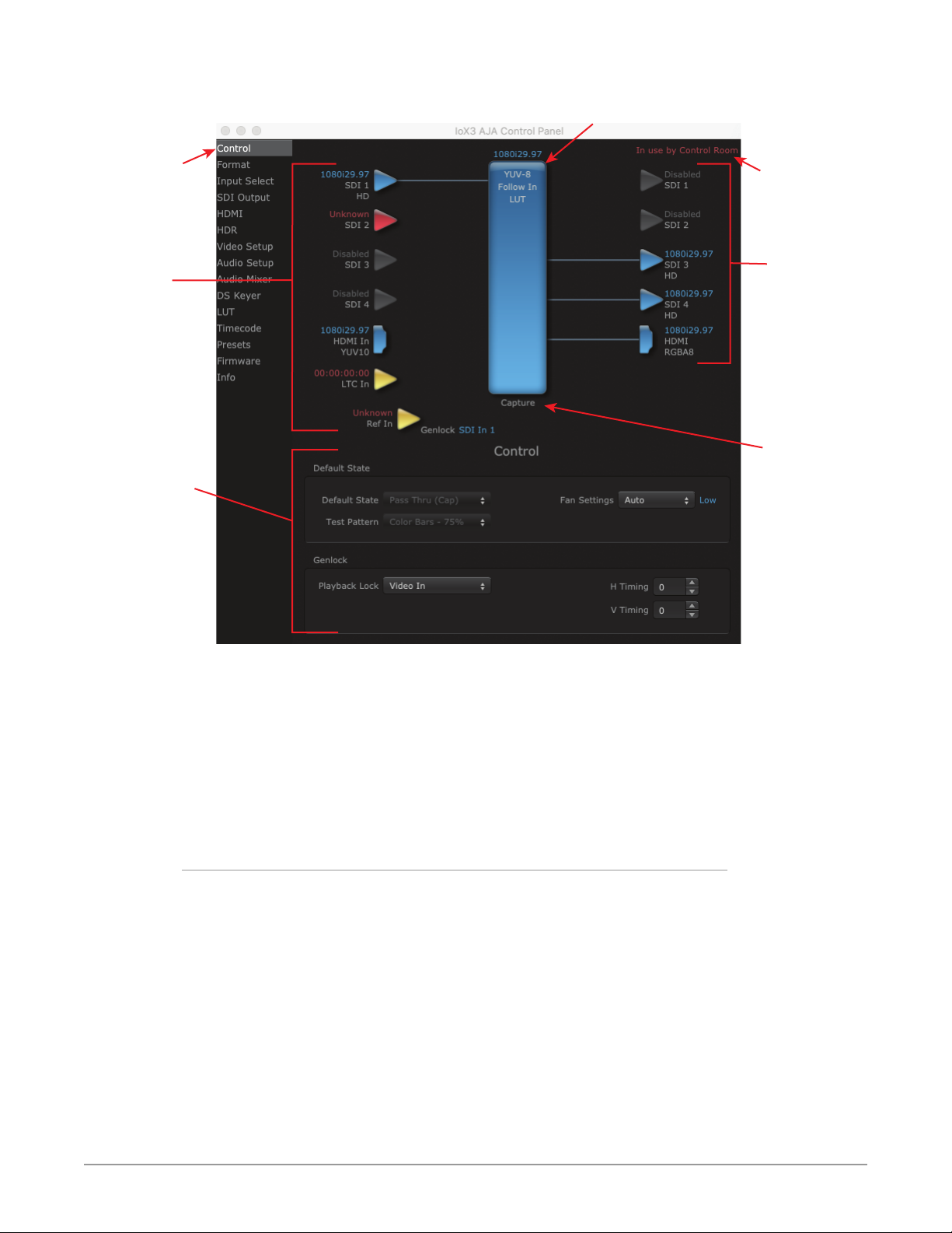
Currently
Selected
Function
Screen
Figure 2. Io X3 Control Panel User Interface
Framebuer Format (Primary)
Controlling
Application
Inputs
Parameter
Controls
Outputs
Operating
Mode
Some controlling applications can switch the card's mode from Playback to
Capture, and vice-versa. When Control Panel is not being controlled by an
external application, you can change the operating mode in the Control Panel
Control Screen using the Default State settings.
• Selecting Passthrough (Cap) sets the card to Capture Mode
• Selecting either Test Pattern (PB) or Hold Last App sets the card to Playback
Mode
See "Default State" on page 20 for more information.
Block Diagram Area
The top block diagram area of the Control Panel screen is a visual representation
of the processing, if any, that’s currently occurring, including inputs/outputs,
reference source, and system status. Lines between inputs, the framebuffer, and
outputs, show a video path. Where there are no lines, there is no connection; this
can be because an input or output isn’t selected in the Input Select menu. The
lines will also show whether the outputs are video or video + key.
You can click any of the function screen selection links in the left column to view
its current settings or click on an icon to call up its related settings screen. You can
also right-click or Control-click to see context-sensitive information and choices
(Figure 3).
Io X3 Capture, Display, Convert v16.2 13 www.aja.com
Page 14
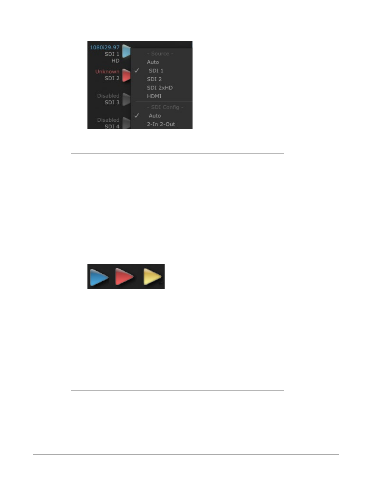
Figure 3. Context Sensitive Menu
Color Meanings
All items in the AJA Control Panel block diagram are color-coded to show what is
happening in real time. This applies to both icons and text. These colors indicate:
Blue - Video is same format as the Device Format (framebuffer)
Yellow - Reference video (black burst or other reference source)
Red - The selected operation cannot be performed
Input/Output Icons
The input and output icons are triangles that together with their color show all
the input and outputs and their status (selected, not selected, input present or
not, format, etc.). A complete video path is shown when inputs and outputs are
connected with lines going to/from the framebuffer.
Figure 4. Input/Output Icons
NOTE: Hovering your cursor over an Input or Output icon opens a tooltip that reports
that connector's signal status (Input signal detected, Output signal enabled,
Input or Output disabled).
Framebuffer
The framebuffer is the “engine” where your third-party applications interface with
the AJA device. The framebuffer has a format (called the “Device Format”) and
color space that it follows, as defined in the linked menu screens or via external
application software.
Device Format
The Device Format is the media format written to disk and used in your project.
This is the format that the framebuffer will use and is shown in the Control Panel
using the color blue. It is the format that the third-party application software will
either receive from the AJA hardware, or is sending to the hardware. All icons in
blue are the same as the Device Format used by the framebuffer. Also any text
descriptions in the block diagram that appear in blue indicate that something is
in the Device Format. For example:
Io X3 Capture, Display, Convert v16.2 14 www.aja.com
Page 15
• If the input and output icons are blue, you know that the same format is used
throughout the video path. No format conversion is being performed.
• If the input or output icon colors differ (blue input and green output icons for
example), you know that a format conversion is being performed.
Controlling Application
It is important to understand that the computer can contain many applications
that can use the AJA device (as you switch from window to window) and it may
not always be obvious which currently controls it.
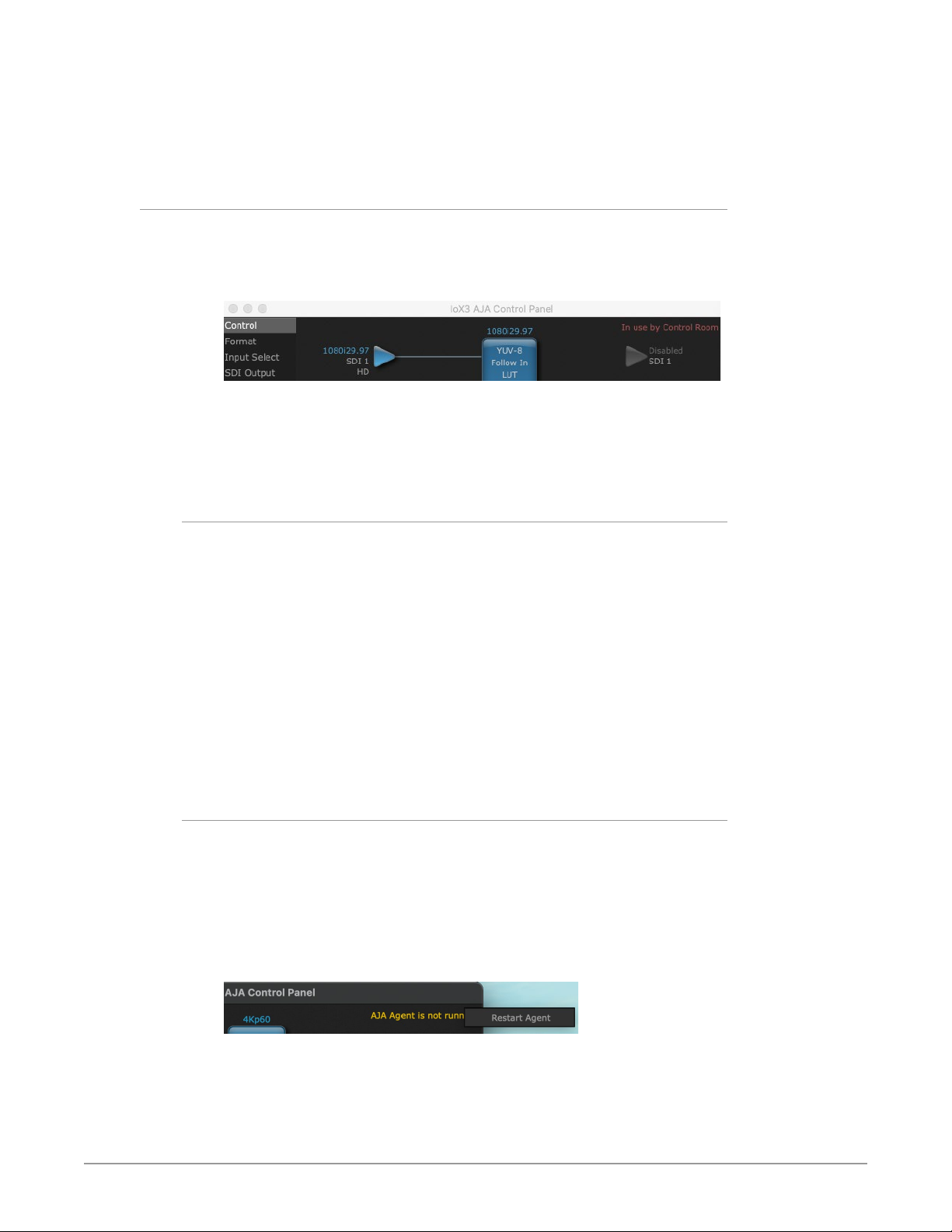
Figure 5. Control Panel In Use Message (in red)
In the top right corner, the Control Panel displays the name of the application
controlling the unit. In some cases, applications may not always properly “let go”
of the I/O interface as another takes over—you’ll be able to tell by looking at the
Control Panel.
Controlling Application Format Selection
If a running controlling application uses Io X3 for capture or output, it controls the
Device Format via its own menus and settings. For example, when the Third-party
editing application is active (it’s the front-most application) and has Io X3 as its
“A/V Device”, the Io X3’s Device Format is determined by the application’s “Video
Playback” settings. These format selections are reported in the AJA Control Panel
block diagram.
Controlling applications can start and stop and change modes—even while they
are running. And the behavior of different controlling applications can vary: some
applications take control of the interface as soon as they are launched and don’t
give it up until they quit, while other applications take control of the interface
only when they are the “front-most” running application and then relinquish
control when they’re not. Even these controlling applications may not relinquish
control until capture or output operations are completed.
AJA Control Panel Restart Services
AJA Control Panel Restart Services is new functionality (since v6.1) that allows for
restarting the AJA services if necessary. This can help if various applications begin
contesting for access to the Video I/O device. In this situation an AJA Agent is
not running message can appear as the controlling application status. Hovering
your cursor over that message displays a Restart Agent button, which clicking on
will bring Control Panel back to its startup state. Then an application can freshly
acquire control of the I/O device.
Figure 6. Restart Services Popup Message
NOTE: On Windows computers you must run Control anel as Administrator in order to
use the restart services feature.
Io X3 Capture, Display, Convert v16.2 15 www.aja.com
Page 16

Control Recommendations
We recommend you have the Control Panel running and visible at all times. When
the Control Panel is running in the background (not front-most) you can see what
the interface is doing and who has control of it.
Presets
Setups can be named and saved as a snapshot (Preset) for recall at any time. You
can save various AJA device Control Panel configurations associated with your
frequent tasks. You don’t have to spend time resetting interface configurations,
just load the previously saved Preset for each task. See "Saving, Loading and
Deleting Presets" on page 46 for more information.
If you work on multiple systems and want to carry your saved setups to another
location, you can copy your saved Preset files on to movable storage and load
them into any computer running the AJA Control Panel application.
Mac OS Preset Files Storage Location
• From the Finder, hold down the Option key (to display the Library directory)
and click on Go/Library/Application Support/AJA/<device name>/Presets/
Windows Preset Files Storage Location
• c:\Users\<username>\AppData\Local\AJA\Control Panel\<device name>
Presets\
Default Preferences
When an AJA device starts up, a preference can determine what settings it will
have it when it begins to operate. The AJA Control Panel offers two default
preference settings:
• Local Preference - A preference stored from the last AJA device's Control Panel
settings to be used on next startup of AJA Control Panel. This occurs on next
restoration of the default state (triggered by start up of host CPU, startup of
the AJA device, or when a third-party application releases the AJA device).
• Global Preference - A preference saved for use as a global default start state
for an AJA device that can be shared by multiple users, applied on first startup,
or by pressing the Control Panel Reset Device... button.
Local Preference
The Local Preference file (com.aja.devicesettings) exists to immediately and
automatically store all parameter changes made by a user on a particular AJA
device. When any control is changed in the Control Panel, that change is recorded
in the Local Preference file stored in a unique location on that computer that is
dedicated to that particular device, serial number, and logged-in user. Then, when
AJA Control Panel is restarted for any reason, the AJA device being controlled
restores the settings being used when Control Panel was last closed.
The Local Preference file can be accessed at the following locations.
On Mac:
• From the Finder, hold down the Option key (to display the Library directory)
and click on Go/Library/Preferences/com.aja.devicesettings.
On Windows:
• C:\Users\<USER_NAME>\AppData\Local\aja\com.aja.devicesettings
Io X3 Capture, Display, Convert v16.2 16 www.aja.com
Page 17

NOTE: Clicking on the AJA Control Panel "Erase All Prefs" button deletes the existing
Local Preference file from this location. This file will be recreated as soon as any
Control Panel setting is changed.
NOTE: Clicking on the AJA Control Panel "Reset Device..." button will delete the existing
Local Preference file. If a Global Preference file is found, these settings are
reloaded. If a Global Preference file is not found, “factory defaults” are loaded and
the device is set to that state
Global Preference
An administrator can establish a house standard for an AJA device by copying
a preference file to a shared computer location. Once placed at that location, it
becomes a Global Preference file where it will establish a standard default startup
state for all users of that AJA device using that computer system. These settings
preempt the initial AJA factory default settings, and are applied when an AJA
device is first powered up, or when the Control Panel Reset Device button is
pressed.
To establish a Global Preference, the administrator first configures the AJA device
(which automatically creates a "com.aja.devicesettings" Local Preference file in
the location identified above) and then copy or move or that file to the correct
computer locations (manually or by pushing it out across the network) on all the
computers that use the AJA device.
NOTE: If the user makes changes to an AJA Device's Control Panel settings, those
changes are saved to the Local Preference file, which will take priority over the
Global Preference file.
The shared computer locations for a Global Preference file are:
On Mac:
• From the Finder, click on Go/Computer/<System HD>/Users/Shared/AJA/
and copy or move the "com.aja.devicesettings file" described above to this
location.
NOTE: The "AJA" folder needs to be created manually at this location before moving the
preference file into it.
On Windows there are three possible shared locations depending on your system:
• C:\Users\Public\Aja\
• C:\Users\All Users\Aja\
• C:\ProgramData\Aja
Copy or move the "com.aja.devicesettings file" described above to one of
these locations.
NOTE: The AJA Control Panel Info screen displays the path to the Global Preference file
on that computer.
NOTE: Clicking on the AJA Control Panel Erase All Prefs button does NOT delete an
existing Global Preference file from this location.
Function Screens
Listed below are the function screens for Io X3 and what they are used for.
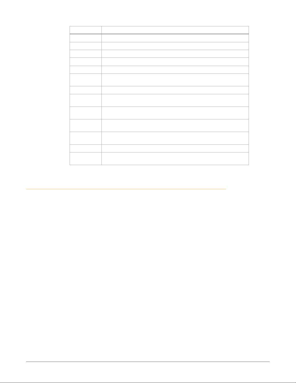
Table 1. Io X3 Function Screens
Screen Functions
Control Configure basic Io X3 operation options and output timing.
Format Select the framebuffer primary video format settings.
Io X3 Capture, Display, Convert v16.2 17 www.aja.com
Page 18
Screen Functions
Input Select View and edit input selections and audio mapping.
SDI Output Select output format.
HDMI Configure the HDMI I/O, including MultiView
HDR Configure High Dynamic Range settings
Video Setup Configure Video such as progressive format and color space.
Audio Setup Configures Audio options such as analog audio input and output
channels, audio monitor level, and audio delay.
Audio Mixer Select and mix audio sources for monitoring.
DS Keyer Setup and control the insertion of keyed video from the frame buffer or
graphics files with alpha channel.
LUT Load a lookup table (LUT) file to adjust the calibration of color for any
source.
Timecode Monitors SMPTE 12M-2 timecode and configure timecode window burn
output.
Presets Add or delete saved preset configurations (handy for quick and easy recall
of different Io X3 settings for varied workflows).
Firmware Install firmware from your currently installed AJA software package.
Info Display status information and the firmware version number. This
information is generally intended for troubleshooting/support.
Io X3 Audio Monitoring
Io X3 hardware can be used as your single audio monitoring solution whether
you are auditioning music in a web browser, playing a movie file on the desktop,
creating music, or playing a YouTube clip. As long as the output of your work
or application is normally output via the host system audio, your AJA hardware
can route this audio for monitoring. This cuts down on unnecessary cabling, and
means you can take advantage of a consistent audio monitoring environment
whatever you are currently doing with your host system.
NOTE: On first use, you will need to tell your operating system to use AJA hardware as
the default Input and Output hardware.
Io X3 lets you listen to Host System audio concurrently with your NLE audio.
This is useful if you need to audition music tracks against playback of your NLE
timeline, or if you need to Skype with a remote producer during an edit session,
or for a myriad of other reasons.
You can also listen to Io X3 Input concurrently with your NLE. This is useful if you
need to listen out for the readiness of talent, or the presence of some other feed,
whilst you continue to work.
Io X3 audio monitoring is routed and mixed using the Control Panel application's
Audio Mixer screen. You can select sources to be monitored, and can adjust
their levels. If you are using the 1/4 inch monitor output connector, an additional
overall mix gain control is conveniently available on the Io X3's front panel.
The mixed audio monitor signal is also routed to:
• SDI Audio out
• HDMI Audio Out
• Analog Audio Out (via DB25 cable)
Io X3 Capture, Display, Convert v16.2 18 www.aja.com
Page 19
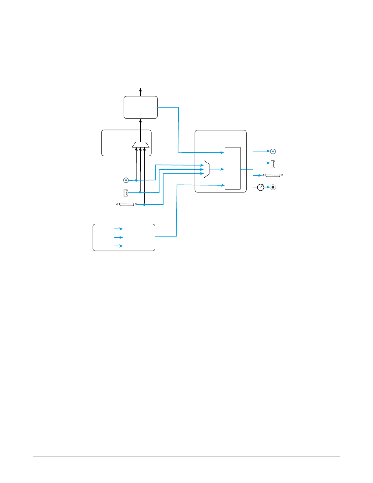
IM PORTANT: Even though you can hear changes in the signals and levels adjusted with
the Audio Mixer screen, these changes are NOT recorded to disk during NLE
Capture or Audio Punch In / Voice Over to Timeline. The Audio Mixer screen is
dedicated for monitoring only, not program mixing.
Figure 7. Io X3 Audio Monitoring Routing Diagram
Audio Capture
Punch In/Voice Over
Record to File
Non Linear
Video Editor
Control Panel
Input Select
Screen
AJA Hardware
Audio Input
SDI Embedded
Audio Input
HDMI Embedded
Audio Input
Analog Audio
Input
NLE
Application
NOTE: NLE audio
output is disabled
in Capture mode.
NLE
Audio
AJA Hardware Audio
Host
Computer
Audio
Control Panel
Audio Mixer
Screen
Mixer
Controls
Gain
Knob
Audio Monitoring
Host Computer Audio Input
Audio File
Playback
YouTube
Other
Sources
Mac or PC
Computer
Audio
To control which AJA hardware audio is used during recording, you use the
Control Panel application's Input Select Screen, Audio Input Select drop down to
select from
• SDI embedded
• HDMI embedded
• Analog (via DB25 cable)
Any level adjustments to Capture or Audio Punch In / Voice Over to Timeline
recording operations will either need to be made upstream of the AJA input, or
else via adjustments within the main NLE application (e.g. via a pass through mix
tool).
AJA Hardware
SDI Embedded
Audio Output
HDMI Embedded
Audio Output
Analog Audio
Output
Front Panel
Monitor Output
Io X3 Capture, Display, Convert v16.2 19 www.aja.com
Page 20
AJA Control Panel Function Screens
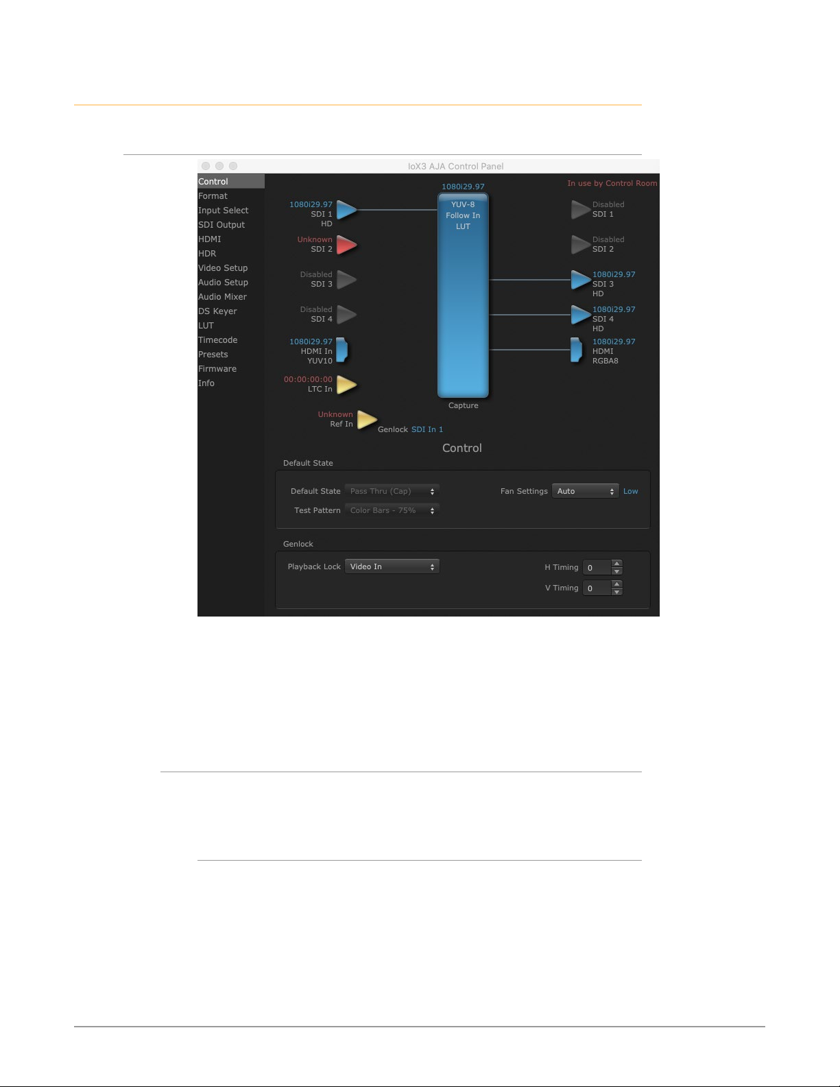
Control Screen
The Control Screen is where you set the Default State, which is what the device
outputs when no application has control of the board. This screen also has
controls for setting the genlock source, and for setting the Horiz and Vert timing
offsets. The top of the Control Screen shows the current state of the device and
also shows the name of the Application which has control of the board, if there is
one.
Default State
Many video applications can grab control of the Io X3, so its outputs can change
dynamically. The Default State settings are used to select what state the Io X3 will
have when no third-party video application is controlling it.
Default State
• Pass Through (Cap) - This selection directs Io X3 to route video from its
selected input through the card for processing and output.
• Test Pattern (PB) - This selection directs Io X3 to output a preset pattern when
no other application is in control. The pattern is selected from the Test Pattern
dropdown list below, or a graphic file can be chosen.
• Hold Last App - This selection directs Io X3 to hold and output the last frame
of video from the last application to control Io X3. This can be helpful when
operating in an environment where you’re switching back and forth between
multiple application windows.
Io X3 Capture, Display, Convert v16.2 20 www.aja.com
Page 21

Test Pat tern
With Test Pattern selected above, you can choose the pattern type. Select from:
• Black, Color bars (75% or 100%), Ramp, Multiburst, Line Sweep, Multi Pattern,
or Flat Field, Check Field, White, Border, Linear Ramp, Slant Ramp, Zone Plate,
Color Quadrant, or Color Quad Border.
For HD with RGB-12 Pixel Formats the following HDR test patterns are available:
• HDR Zone Plate, HDR Linear Ramp, HDR HLG Narrow, HDR PQ Narrow, or HDR
PQ Wide.
Graphic File Display
In addition to the test patterns above, a “Load File...” selection at the bottom
of the Test Pattern dropdown menu allows you to load a standard RGB/RGBA
graphics file (.tif,.psd, etc.) into the frame buffer for display (including alpha
channel). Some graphics formats and bit depths may not be supported. Files that
have been loaded are listed for quick reuse. Loaded graphic files are retained for
redisplay if another test pattern is selected, and even if Io X3 is power cycled.
NOTE: A loaded graphics file will not be scaled to fit. If it’s smaller than the current frame
buffer format,Io X3 will center it in the frame. If larger than the current frame
buffer format it will be cropped.
• Clear Files - This selection on the pulldown clears all the Graphic Display files.
Fan Settings
Io X3 offers a fan speed control. The High setting forces maximum fan cooling,
with some increased noise, but this setting could be appropriate if the unit is
located in, for example, a machine room rather than an editing suite.
• Auto - Fan speed controlled by temperature, increasing or decreasing
automatically.
• High - Fan always operates at its highest speed.
Genlock
Use these controls to select Io X3 Genlock settings and adjust Timing.
Playback Mode has three Playback Lock settings:
• Auto: Automatically sets the recommended default settings of Free Run for
Playback mode and Video In for Capture mode
• Free Run: Generates sync without an external reference source
• Reference In: Uses the Ref Video source for sync (usually an analog black burst
video signal)
• Video In: Uses whichever video input source has been selected in the Inputs
screen for sync
Alternative Genlock settings will not cause capture or playback errors, but will
make the NLE system take a bit longer shut down in one mode and then lock
back up in the other mode, during which time some flashing may appear on the
monitor.
Timing (Horiz and Vert)
These two pull-downs allow output timing adjustment with reference to the Ref
Video source selected.
• Horizontal: The Horizontal reference can be adjusted by selecting a number of
pixels (clocks) to offset
• Vertical: The vertical reference can be adjusted by specifying a number of lines
to offset.
Io X3 Capture, Display, Convert v16.2 21 www.aja.com
Page 22
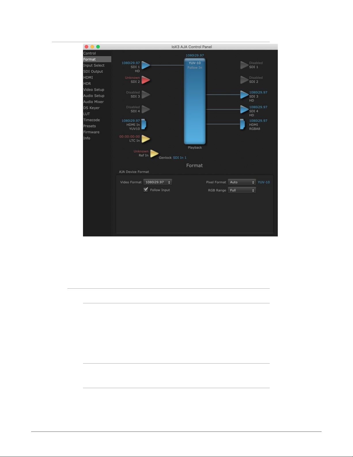
Format Screen
The Format Screen shows the video format currently in use by the Io X3
framebuffer (called the Device Format) and allows you to change it. All
throughout the Control Panel, choices are always presented based on what Io X3
can do with the signals available and the inputs/outputs selected.
AJA Device Format
Video Format
This pull-down menu shows the currently selected Device format. If you select
an alternate value using the pull-down, it will change the format used by Io X3’s
framebuffer.
When a change is made via the Video Format pull-down or by clicking an icon
and selecting a new format via a contextual menu, the block diagram will change
to reflect the new format.
Pixel Format
Use this pulldown menu to choose: YUV-8, YUV-10, ARGB-8, RGB-10, or RGB-12.
RGB Range
The RGB Range pulldown menu allows you to select either Auto, Full-range (0-
1023) or SMPTE range (typically 64-940) for RGB color output.
Io X3 Capture, Display, Convert v16.2 22 www.aja.com
Page 23
NOTE: The AJA Control Panel software uses the abbreviation “sf” instead of “PsF” when
referring to “progressive segmented frame” formats. In the manual and in other
literature you may see either of these acronyms used interchangeably. Visually, it
is easier to recognize:
• “sf” for progressively segmented frame formats
• “p” for progressive frame formats
Follow Input
Enabling the Follow Input checkbox allows the Control Panel Frame Buffer
to auto-switch to the detected input format. This feature works only if the
controlling application supports input-based capture—AJA Control Room for
example.
NOTE: RGB Range is only used when the SDI input or output is configured for RGB.
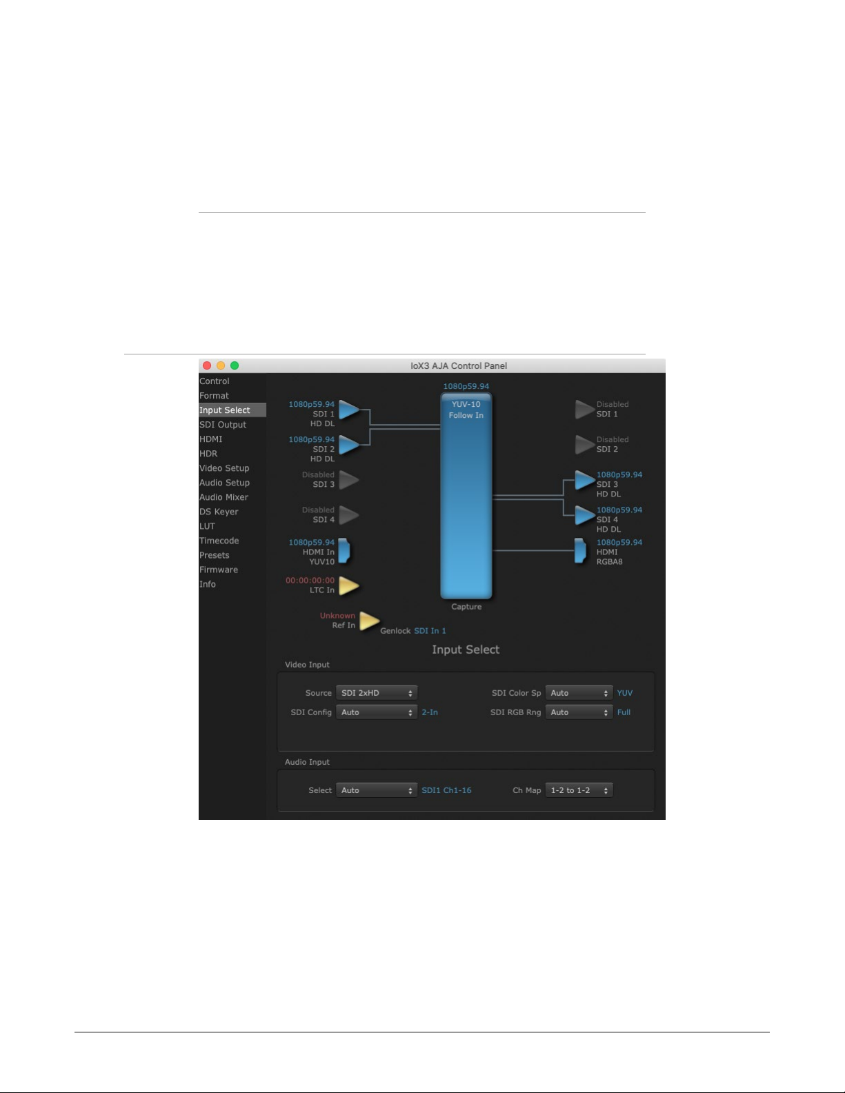
Input Select Screen
On the Input Select screen you can view or set the currently selected video and
audio input sources and map audio sources to the channels supported by your
editing application. Two information panes in the screen are provided: Video
Input and Audio Input.
Io X3 Capture, Display, Convert v16.2 23 www.aja.com
Page 24

Video Input
Source
The pulldown menu allows you to select the currently selected video input
source. Select from:
• Auto - Automatically selects the source depending on input format.
• SDI 1, SDI 2, SDI 3, or SDI 4
• SDI 2x HD
• HDMI
SDI Config
• Auto - Automatically selects the source depending on input format.
• 2-In 2-Out - SDI 1 and SDI 2 will be used for individual input sources and SDI 3
and SDI 4 will be used for outputs.
• 4-In - SDI 1 - 4 will all be used for individual input sources, required for
MultiView operation.
NOTE: Only HD input sources can be used when "4-In" is selected for SDI Config and
"MultiView" is selected for HDMI Output. See "HDMI Screen" on page 27 for
more information.
SDI Color Sp
• Sets the color space. Select from Auto, YUV, or RGB.
SDI RGB Rng
Sets the RGB range. Select from Auto, SMPTE, or Full.
Audio Input
Select
This pulldown menu allows you to pick where the audio comes from. Select from:
• Auto
• Analog
• HDMI
• SDI 1 Ch1-16
• SDI 2 Ch1-16
Ch Map
If only two channels were selected in the third-party application you are using,
you can select which two channels will be mapped to that application. Different
Audio Input selections have different channel mapping capabilities. Select from:
• 1-2 to 1-2
• 3-4 to 1-2
• 5-6 to 1-2
• 7-8 to 1-2
• 9-10 to 1-2
• 11-12 to 1-2
• 13-14 to 1-2
• 15-16 to 1-2
NOTE: This setting does not affect the embedded audio being sent to the Io X3's BNC or
HDMI output connectors.
Io X3 Capture, Display, Convert v16.2 24 www.aja.com
Page 25
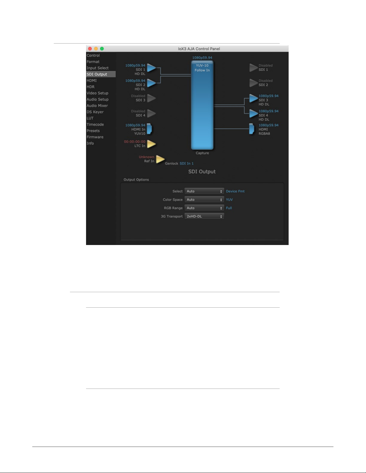
SDI Output Screen
The SDI Output screen shows the current settings for the SDI outputs. The
outputs can be configured independently. If an input/output has no video, it will
be indicated on the block diagram (“No Video”).
Output Options
Select
• Auto - Automatically selects the output format, based on the input or selected
format.
• Device Format - Selects the framebuffer format for output.
• Video+Key - When selected, this indicates that the SDI 3 video is set to the
same format as the framebuffer. SDI 4 is set to a video key signal associated
with SDI 3 (the shape to be cut out from the video, which will appear as a black
and white image/matte). Using the second Io X3 output as an Alpha Channel
key, with the video output, may be useful for feeding production switchers,
DVEs or other professional video equipment.
Color Space
The Color Space pulldown allows you to choose between two “Auto” modes, or
to explicitly force the output to a desired color space regardless of the attached
device’s EDID or user application needs.
• Auto Detect - (most reliable) AJA device attempt to reconfigure the HDMI
output to match the current color space setting of the output monitor EDID.
This option will be the most reliable in creating an output image. However, the
Io X3 Capture, Display, Convert v16.2 25 www.aja.com
Page 26

output may result in an inferior image due to color space conversion and loss
of bit depth.
• Auto - The AJA device will attempt to automatically set the output monitor
into the best color space and bit depth regardless of EDID of the output
monitor. This may result in loss of image if the output monitor does not
support a specific color space.
• RGB - Forces the use of RGB (required for LUT operations).
• YUV - Forces the use of YUV.
RGB Range
Sets the RGB range. Select from Auto, SMPTE, or Full.
3G Transpor t
Sets the output transport. Select from:
• Auto - Auto selection based on input or selected format.
• 2xHD-DL: Dual link HD output using two BNCs. The Level B-DL format is the
mapping of dual-link HD-SDI/SMPTE 372M (i.e.: 1080p up to 60 fps) in a single
serial digital interface at the nominal 3 Gbit/s.
• 3Gb - Single link HD output using one BNC. The Level B-DS format is the dualstream carriage of two independent HD-SDI/SMPTE 292M signals (720p up
to 60 fps or 1080i/1080p up to 30 fps) in a single serial digital interface at the
nominal 3 Gbit/s.
• 3Ga - Single link HD output using one BNC. The Level A format is the direct
mapping of uncompressed 1080p (up to 60 fps) video into a serial digital
interface at the nominal 3 Gbit/s.
Io X3 Capture, Display, Convert v16.2 26 www.aja.com
Page 27
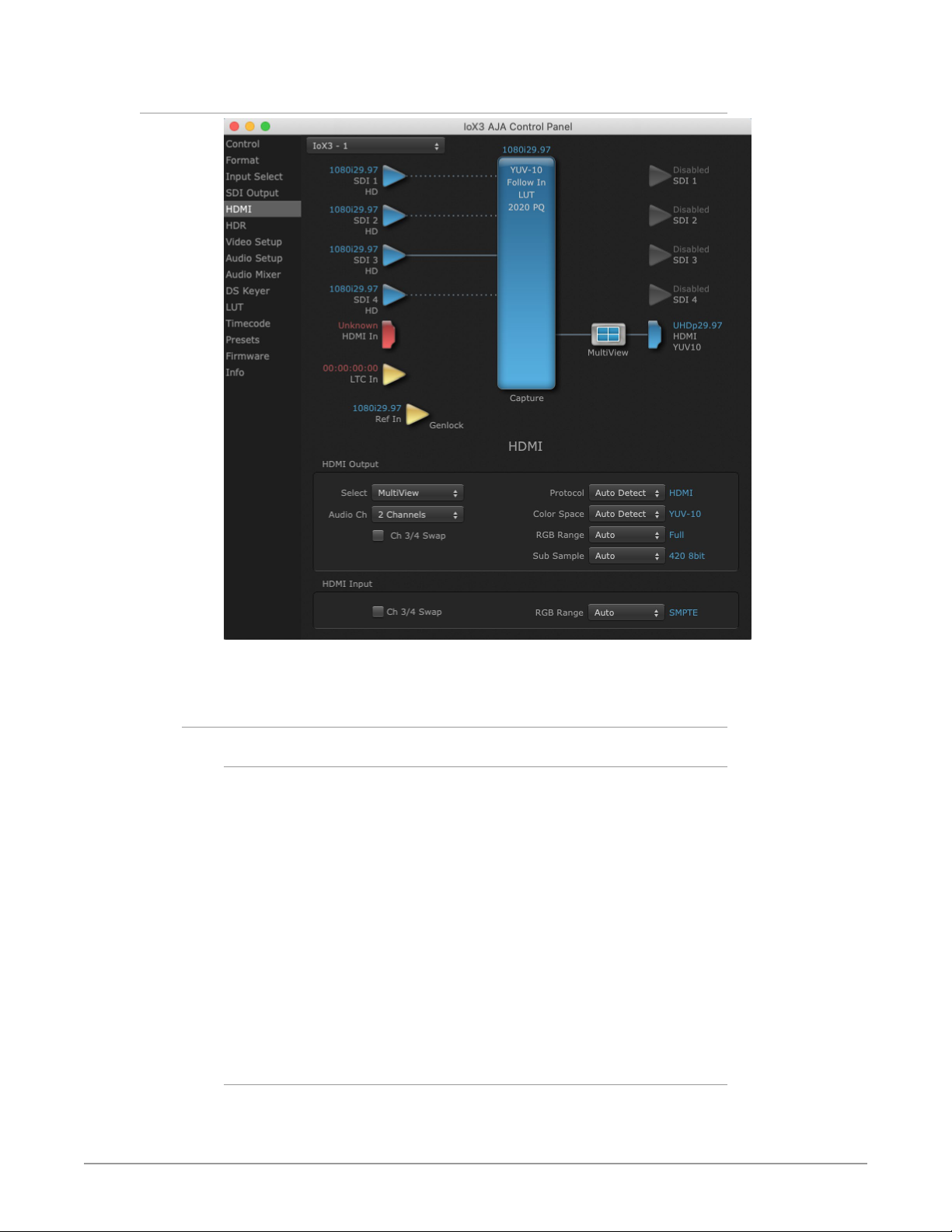
HDMI Screen
The HDMI input and output are configured with this screen.
HDMI Output
Select
This pulldown lets you select the type of HDMI output.
• Auto - Automatically sets the HDMI output format, based on the input or
selected format.
• Device Format - Outputs the selected SD/HD input to the HDMI's output.
• MultiView - Used to create a multi-viewer confidence display of up to four
independent HD input signals on the Io X3's HDMI output. The HDMI monitor
must be capable of UltraHD. Dotted input lines on the screen indicate
MulitView mode is active. The single solid line identifies which input audio will
be routed to the HDMI MultiView output (default SDI 1), and also which video
and audio source will be used by a controlling application capable of single
source capture.
NOTE: Only HD input sources can be used when "4-In" is selected for SDI Config and
"MultiView" is selected for HDMI Output. See "Input Select Screen" on page 23
for more information.
Audio Ch
This pulldown allows you to select the number of embedded audio channels for
the HDMI output. Select from:
• 2 Channels
Io X3 Capture, Display, Convert v16.2 27 www.aja.com
Page 28

• 8 Channels
Ch 3/4 Swap
This checkbox controls HDMI input audio channel placement. Some multichannel audio decoder systems route the low frequency effects audio to channel
4, and some to channel 3. If you want to monitor or pass audio though to another
device, this control can be used to align these two channels correctly.
• Checked - (default) HDMI audio channel 3 is moved to channel 4's location,
and input channel 4 is moved to channel 3's location.
• Unchecked - HDMI audio retains the original 3 and 4 channel locations.
Protocol
This pulldown allows you to choose:
• Auto Detect – (most reliable) AJA device attempts to reconfigure the HDMI
output to match the current protocol setting of the output monitor. This
option will be the most reliable in creating an output image. However, the
output may result in loss of audio.
• Auto Set – (best quality) The AJA device HDMI out will attempt to
automatically set the output monitor into the best protocol, usually HDMI.
• HDMI – Forces the use of the HDMI protocol regardless of the attached
device’s EDID. Connection may fail if output monitor does not support the
HDMI protocol.
• DVI – Forces the use of the DVI protocol regardless of the attached device’s
EDID.
Color Space
Sets the color space bit depth. Select from:
• Auto Detect - Selects the appropriate color space depending on signal.
• Auto Set - (best quality) The AJA device will attempt to automatically set the
output monitor into the best color space and bit depth that matches the user's
application needs regardless of EDID of the output monitor. This may result
in loss of image if the output monitor does not support a specific color space
mode.
• RGBA-8 - Selects RGBA 8 bit.
• RGB-10 - Selects RGB 10 bit.
• RGB-12 - Selects RGB 12 bit.
• YUV-10 - Selects YUB 10 bit.
RGB Range
This pulldown lets you configure video output range. Choose from:
• SMPTE
• Full
Sub Sample
Determines the output of the quad display when MultiView has been selected.
• Auto – (best quality) The AJA device will attempt to automatically set the
output monitor into the best color space and bit depth that matches the user's
application needs regardless of EDID of the output monitor. This may result
in loss of image if the output monitor does not support a specific color space
mode.
• 420 8-bit - Displays each quadrant of the MultiView display as 420 8-bit.
• Half Rate - Changes a MultiView display High Frame Rate output to a Low
Frame Rate output.
Io X3 Capture, Display, Convert v16.2 28 www.aja.com
Page 29
HDMI Input
The detected HDMI input video format is displayed and you’re given a chance to
configure the RGB range of the HDMI input.
Audio Ch 3/4 Swap
This checkbox controls HDMI output audio channel placement. Some multichannel audio decoder systems route the low frequency effects audio to channel
4, and some to channel 3. If you want to monitor multi-channel audio directly or
pass audio though to another device, this control can be used to place these two
channels correctly.
• Checked - (default) HDMI audio channel 3 is moved to channel 4's location,
and input channel 4 is moved to channel 3's location.
• Unchecked - HDMI audio retains the original 3 and 4 channel locations.
RGB Range
Choose from:
• SMPTE
• Full
HDR Screens
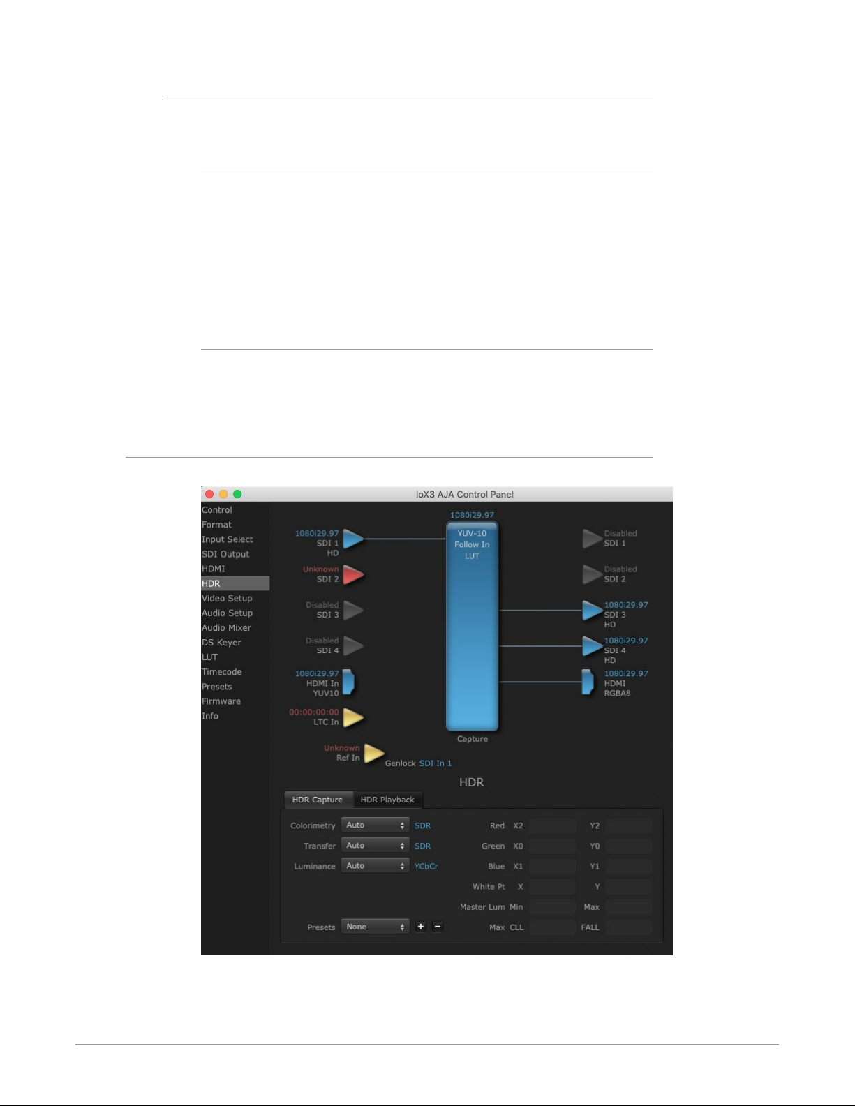
Figure 8. HDR Capture Screen Tab
Io X3 Capture, Display, Convert v16.2 29 www.aja.com
Page 30
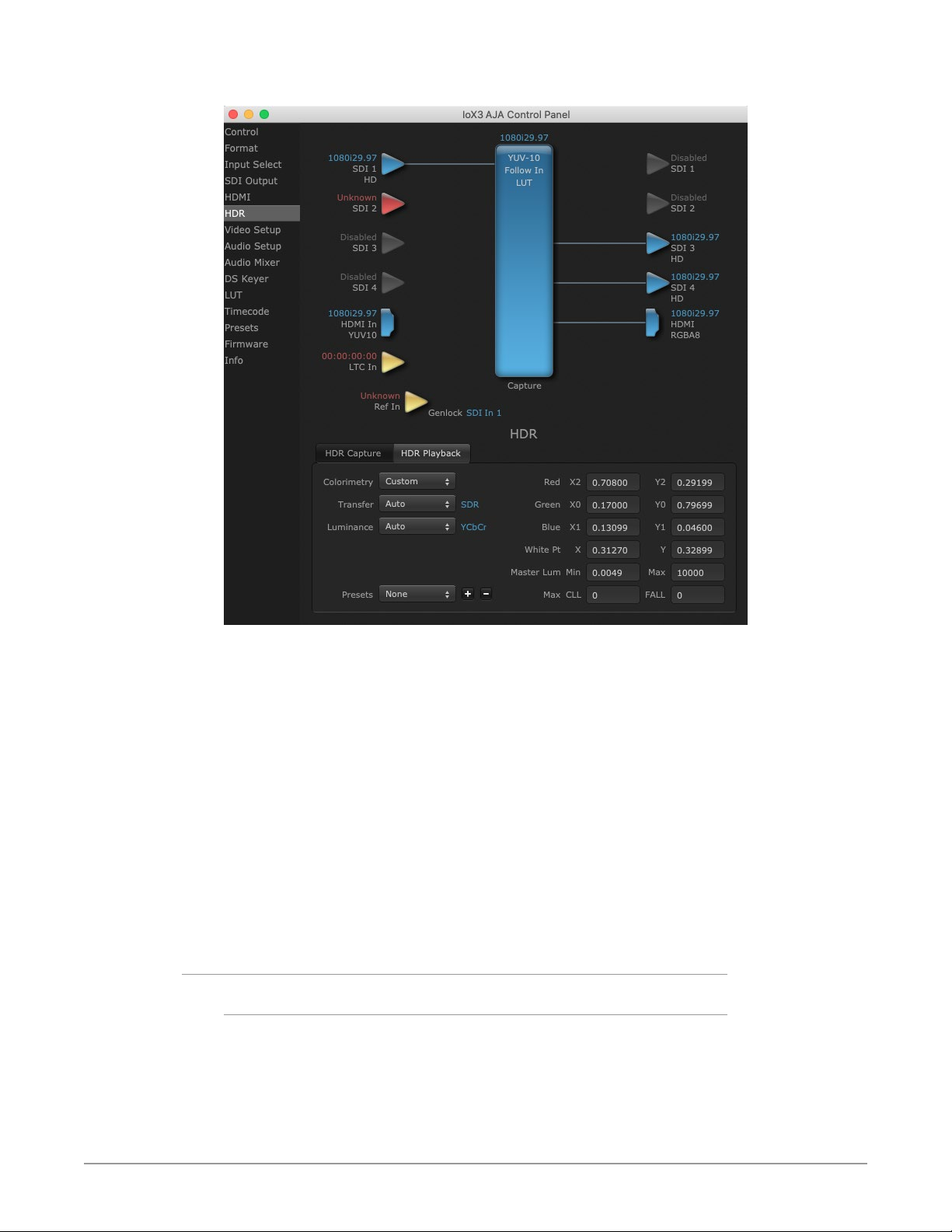
Figure 9. HDR Playback Screen Tab
The HDR screen provides a sub tab setup for HDR playback simultaneously via
both SDI and HDMI.
For SDI destinations, the HDR data is delivered in-band using VPID signaling for
SDR/HDR Transfer Characteristics, Colorimetry and Luminance.
For HDMI destinations, side-band information is used to inform an HDMI sink
device (such as a TV or monitor) that the video content is HDR. This includes
generation of the Dynamic Range and Mastering Infoframe and the static
metadata descriptors as defined in CTA-861.3 and HDMI v2.0a.
Included are preset primaries values for BT.2020 and DCI P3 color gamuts.
Two tabbed screens are available, for Capture and Playback. The HDR Capture tab
settings affect the HDR metadata saved with your captured video, and the Io X3's
HDMI and SDI outputs while in Capture mode. The HDR Playback tab settings
affect what HDR metatdata is included on the Io X3's HDMI and SDI outputs while
in Playback mode.
HDR Capture Settings
Colorimetry
• Auto - (default)
• SDR - Standard Dynamic Range
• P3 - P3 colorspace
• 2020 - BT.2020, typically used with HDR
• Custom - Allows custom values for the Digital Primaries.
Io X3 Capture, Display, Convert v16.2 30 www.aja.com
Page 31

Transfer
The Electrical Optical Transfer Function metadata bit tells the HDMI display which
EOTF to use.
• Auto - (default)
• SDR - Standard Dynamic Range
• PQ - Perceptual Quantizer
• HLG (Hybrid Log Gamma) - No meta-data for Digital Primaries.
Luminance
• Auto - (default)
• YCbCr -
• ICtCp - IPT color space
Digital Primaries
Selecting Custom HDR Mode allows the editing of digital primaries information
that is passed as metadata accompanying the video signal. However, when HLG
selected as the EOTF digital primaries information cannot be edited, because HLG
does not use metadata.
Display Mastering Luminance
Represents the minimum and maximum Display Mastering Luminance.
• Minimum: Defines the floor of the SMPTE ST 2086 color volume (in the case of
HDR) and is determined by the mastering environment.
• Range: 0.0000 cd/m2 to 1.0000 cd/m2.
• Step size: 0.0002 cd/m2.
• Maximum: Defines the ceiling of the SMPTE ST 2086 color volume (in the case
of HDR) and is determined by the mastering environment.
• Range: 1 cd/m2 to 65535 cd/m2.
• Step size: 1 cd/m2.
Maximum Content Light Level (CLL)
Represents the highest-value pixel component in an entire scene. It is
determined by analyzing each frame of video, and can be determined in the post
environment.
• Range: 1 cd/m2 to 65535 cd/m2.
• Step size: 1 cd/m2.
Maximum Frame Average Light Level (FALL)
Represents the maximum of frame-based average light levels taken over an entire
scene, and can be determined in the post environment.
• Range: 1 cd/m2 to 65535 cd/m2.
• Step size: 1 cd/m2.
HDR Playback Settings
The HDR Playback tab settings are identical to the HDR Capture settings, but
affect the Io X3's HDMI and SDI outputs.
Io X3 Capture, Display, Convert v16.2 31 www.aja.com
Page 32
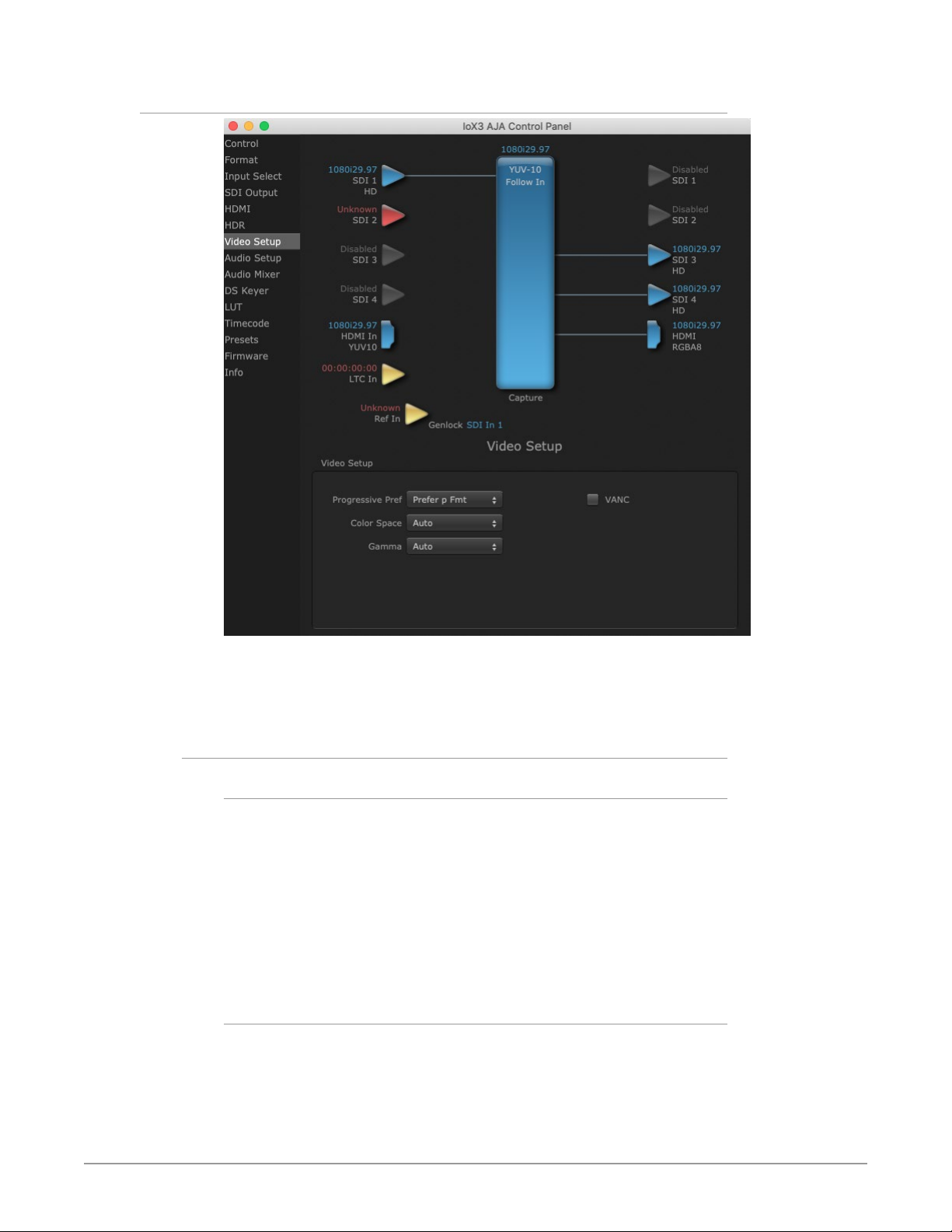
Video Setup Screen
The Video Setup screen shows various other settings which will affect how
video inputs and outputs behave, and how Io X3 interacts with some software
applications.
Video Setup
Progressive Pref
This feature is used to default the hardware to use either p or PsF output over SDI
when it has not been specified by the application. Choose between:
• Prefer p Format - progressive frames non-interlaced output
• Prefer psf Format - progressive segmented frames
NOTE: If you change this option while your NLE is open and running, you may need to
then make a change in one of your NLE settings in order for this to be reflected
dynamically in the project. For example in Media Composer, simply toggling
the Video Quality menu in the Timeline should cause a project format refresh to
occur, thus recognizing the change you just made in Control Panel.
Color Space
Sets the video color space. Select from:
• Auto
• Rec 601
• Rec 709
Io X3 Capture, Display, Convert v16.2 32 www.aja.com
Page 33
Gamma
Sets the video gamma. Intended for use with legacy Apple displays. Select from:
• Auto
• Gamma 1.8
VANC Checkbox
When checked, the VANC checkbox tells the Io X3 to capture and process any
ancillary data in the SDI stream. This can include different types of metadata.
Applications such as Premiere Pro and Final Cut Pro will not capture or output this
data through the Io X3 if this box is not checked.
NOTE: Io X3 does not require enabling the VANC checkbox for Closed Captioning.
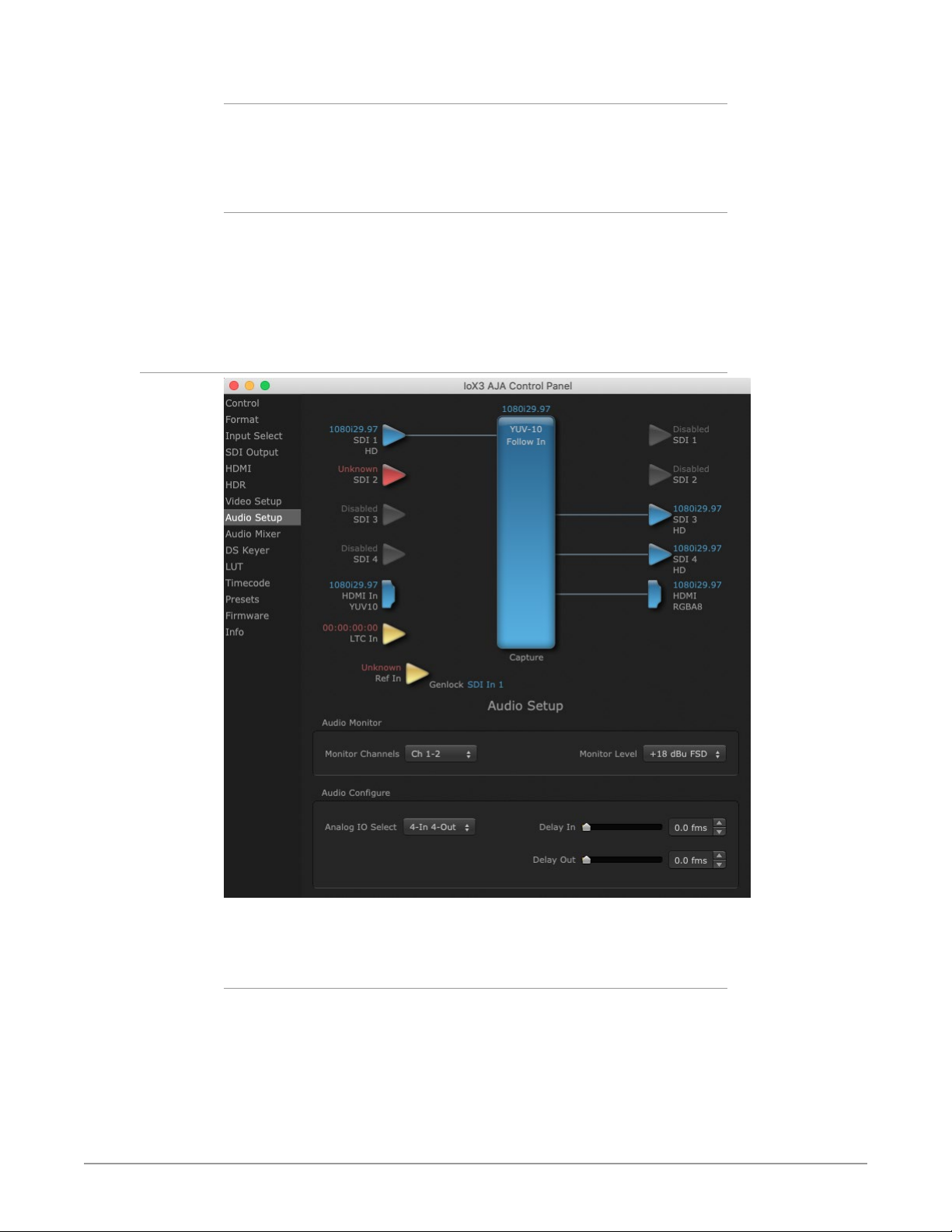
Audio Setup Screen
The Audio Setup screen shows the current settings for the analog audio output,
allowing you to re-configure it when desired.
Audio Monitor
This control selects which pair of channels from the NLE will be monitored. For
most editing scenarios this should remain as Ch 1-2, since most NLEs default to
dual track / stereo monitoring as a sum of the entire timeline.
NOTE: This setting only applies to dual channel monitoring environments (for example,
the headphone jack on the front of the Io X3).
Select from:
• Ch 1-2 through Ch 15-16
Io X3 Capture, Display, Convert v16.2 33 www.aja.com
Page 34

Analog Audio Monitor Level
This selection determines the analog audio output level (“FSD” is full-scaledeflection reading as measured on a VU meter). In addition to the front panel
monitor (headphone) output, this setting also effects the analog output via the
DB25 cable. Select from
• +24dBu, +18dBu, +15dBu, or +12dBu
Analog IO Select
This setting configures the analog audio input and output channels on the DB-25
connector. Choose from:
• 8-Out
• 4-In 4-Out (Ch 1-4 in, Ch 5-8 out)
• 4-Out 4-In (Ch 1-4 out, Ch 5-8 in)
• 8-In
Delay In and Out
Here you can set up to 6 frames (in tenths of a frame) of delay for the AJA device’s
audio input and output. The AJA Control Panel delays all audio outputs—SDI,
HDMI, and Analog. This feature is useful in compensating for the processing delay
of a video monitor when audio is being monitored directly from the Io X3 (for
example, when an audio mixer is connected to the DB25 analog audio inputs).
IM PORTANT: If you use this Control Panel delay, do not use other delay settings in your
applications, as they can conflict with one another.
Audio Mixer Screens
The Audio Mixer screen has two tabs; Capture Monitor and Playback Monitor.
These tabs display what sources are available for monitoring / mixing via the AJA
hardware when in either of those two modes (if applicable). The controls on this
screen are dedicated only to monitoring adjustments, and do not affect the level
at which inbound audio signals are captured to storage.
The selection check boxes and screen slider controls affect the following Io X3
outputs:
• SDI Embedded Audio Out
• HDMI Embedded Audio Out
• Analog Audio Out (via DB25 cable)
• Front Panel Monitor Out (headphone jack) - This level can also be adjusted
with the front panel gain knob, and is additive to the screen slider controls.
IM PORTANT: Even though you can hear changes in the signals and levels adjusted
with the Audio Mixer screen, these changes are NOT recorded to disk during
NLE Capture or Audio Punch In / Voice Over to Timeline. In addition, muting or
activating sources on this screen will not affect audio signals being recorded. The
Audio Mixer screen is dedicated for monitoring only, not program mixing.
The branching arrow on the lower right indicates which sources are being routed
for monitoring in that operating mode, and is colored blue when active and red
when disabled.
Io X3 Capture, Display, Convert v16.2 34 www.aja.com
Page 35
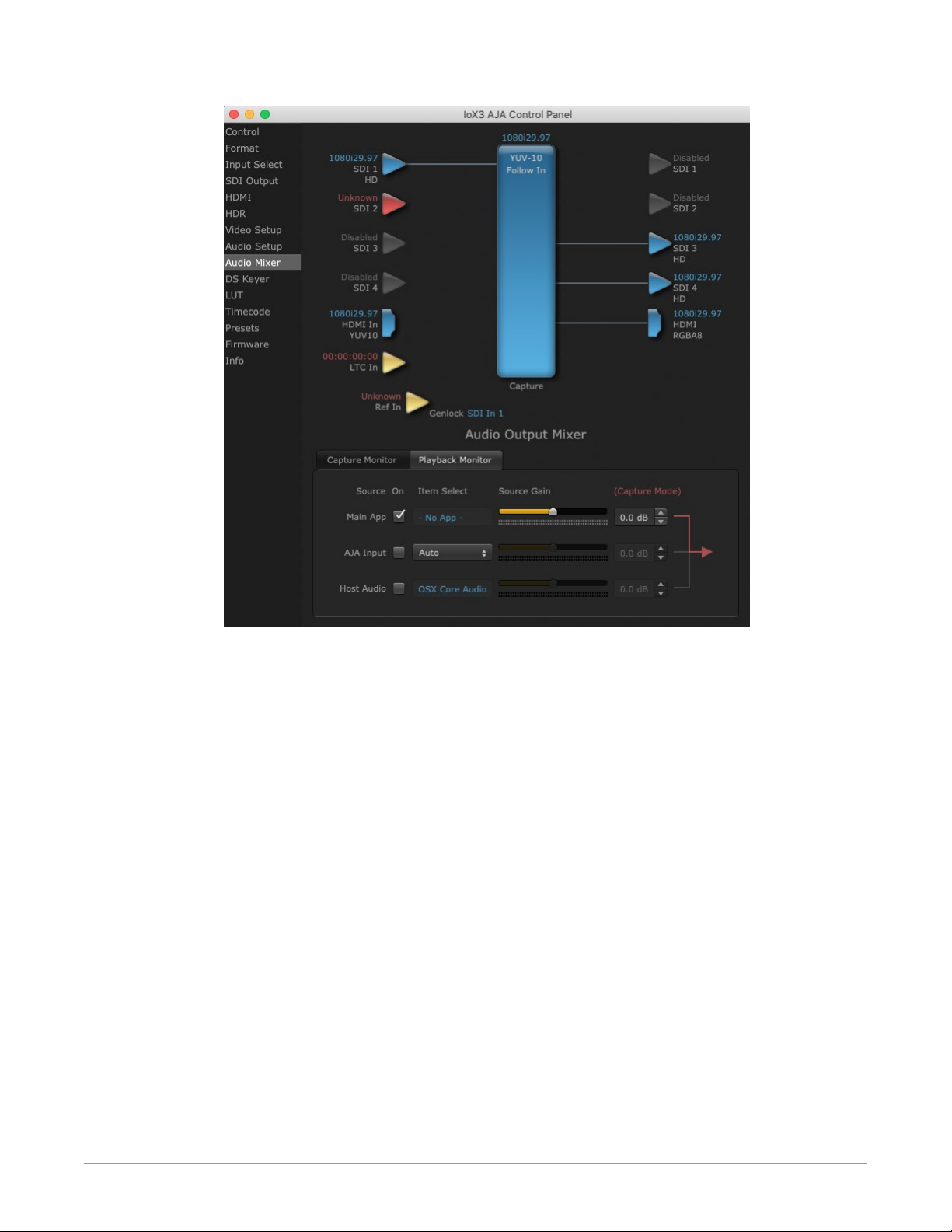
Figure 10. Audio Mixer Screen Example
Each source has a confidence meter, which enables you to tell immediately if you
have a source arriving correctly at the AJA hardware (without having to launch
any other software). The level sliders allow a simple plus or minus adjustment to
the Source level being monitored. This is to allow for fine-tuning of your listening
environment (on occasions the host system audio can be unexpectedly loud, or
an incoming feed may be very loud or very quiet).
Two different Audio Mixer screens are available, selected by clicking on the
Playback Monitor or Capture Monitor tabs. During regular editing, the Playback
tab is used to control your monitoring experience. During capture operations, the
Capture tab is used for your monitoring experience.
Controls in each tab are only in effect when Io X3 is in the correct operating
mode, as determined by the controlling application or the Control Panel
application's Default State setting. When the mode doesn't match, the mode
indicator on the right goes red (see Figure 10 on page 35). However, settings can
be adjusted while in that disabled mode, and will be applied when you return to
that operating mode.
Io X3 Capture, Display, Convert v16.2 35 www.aja.com
Page 36
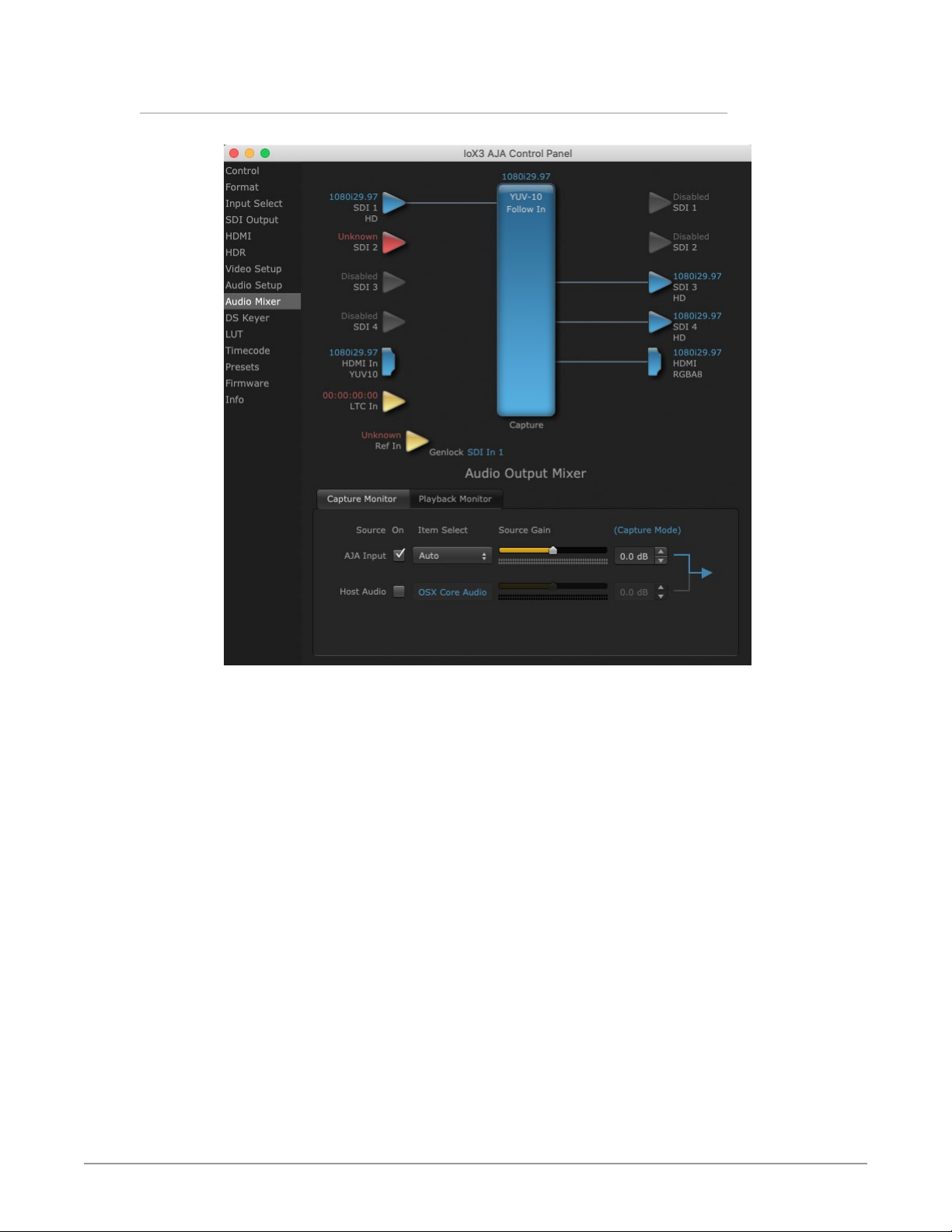
Audio Mixer Capture Monitor Mode Screen
Figure 11. Audio Mixer Screen, Capture Monitor Mode
The Capture Monitor Mode screen is used to select and mix audio to be
monitored during capture operations.
IM PORTANT: Even though you can hear changes in the signals and levels adjusted
with the Audio Mixer screen, these changes are NOT recorded to disk during
NLE Capture or Audio Punch In / Voice Over to Timeline. In addition, muting or
activating sources on this screen will not affect audio signals being recorded. The
Audio Mixer screen is dedicated for monitoring only, not program mixing.
The controls on this screen are similar to those on the Playback Monitor Mode
screen, except the Main App is not available for selection (you cannot capture
from the application that is capturing). See "Audio Mixer Playback Monitor Mode
Screen" on page 37 for more information.
NOTE: If you want different behavior when the Capture tab is triggered; i.e. for host
system audio to be muted, then simply check the host system audio in the
Capture tab only. This way when you exit NLE Capture and return to regular
editing, the Playback tab settings will be applied and your host system audio
monitoring will resume.
Io X3 Capture, Display, Convert v16.2 36 www.aja.com
Page 37
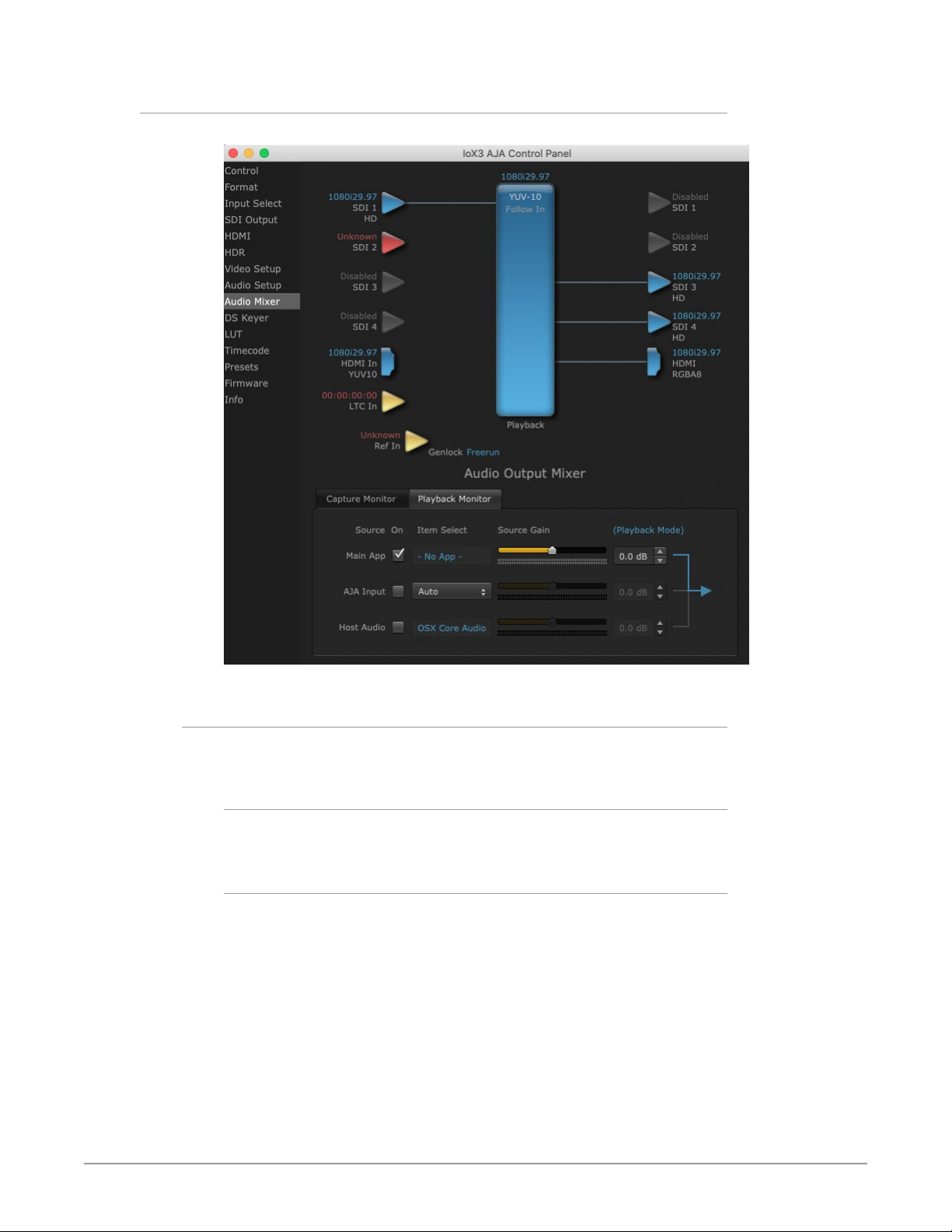
Audio Mixer Playback Monitor Mode Screen
Figure 12. Audio Mixer Screen, Playback Monitor Mode
Playback Source Selection
Clicking the On checkbox selects the audio for that item for playback to the audio
monitor outputs. Multiple sources can be selected simultaneously.
Main App
If an external application is controlling the Io X3, it will be displayed in the Item
Select column and its audio can be selected for playback with the checkbox.
AJA Input
Selects for monitoring the audio being input to Io X3.
NOTE: The AJA Input Item Select dropdown selection is linked to the Input Select screen's
Audio Input Select dropdown. Changing the setting on one screen will also
change the setting on the other screen.
In the Item Select column, click on the dropdown and choose from:
• Analog - The Analog Audio being received on the Io X3, DB-25 connector.
• HDMI - The embedded audio being received on the Io X3 HDMI In connector.
• SDI Ch 1-16 - The embedded audio being received on the Io X3 SDI In
connectors.
Io X3 Capture, Display, Convert v16.2 37 www.aja.com
Page 38

Host Audio
Selects the audio from the host computer, thus enabling the AJA hardware to
monitor anything that would normally be presented via the host laptop, CPU or
computer monitor. For example, an editor could sample music from an online
library, while concurrently playing back their NLE timeline. Or, a producer and
editor could be communicating live during an editing session, using Skype or
some other video calling tool.
Source Gain
Meters display the input audio levels of the source, colored green when that
source is On, and gray when that source is not selected. The levels shown do not
change when the gain is adjusted, because the input levels are being monitored,
not the output levels.
When activated, the source gain controls can be used to adjust the monitoring
output gain of that source, from +6dB to - infinity (mute). Adjustment methods
include:
• Sliders - The sliders on the right can be used to change the values for each
color.
• Numeric Entry - You also enter a numeric value by clicking on the displayed
number, and can increase or decrease the values clicking on the up/down
arrow boxes.
• Cut and Paste - Right clicking on a displayed number opens a Cut, Copy, Paste
dropdown menu for convenient numeric entry.
As mentioned before, these controls are for monitoring only, and do not change
the audio recorded to a NLE file. Any actual recording level adjustments to
Capture or Audio Punch In / Voice Over to Timeline operations will either need to
be made upstream of the AJA input, or else via adjustments within the main NLE
application (e.g. via a pass through mix tool).
Io X3 Capture, Display, Convert v16.2 38 www.aja.com
Page 39
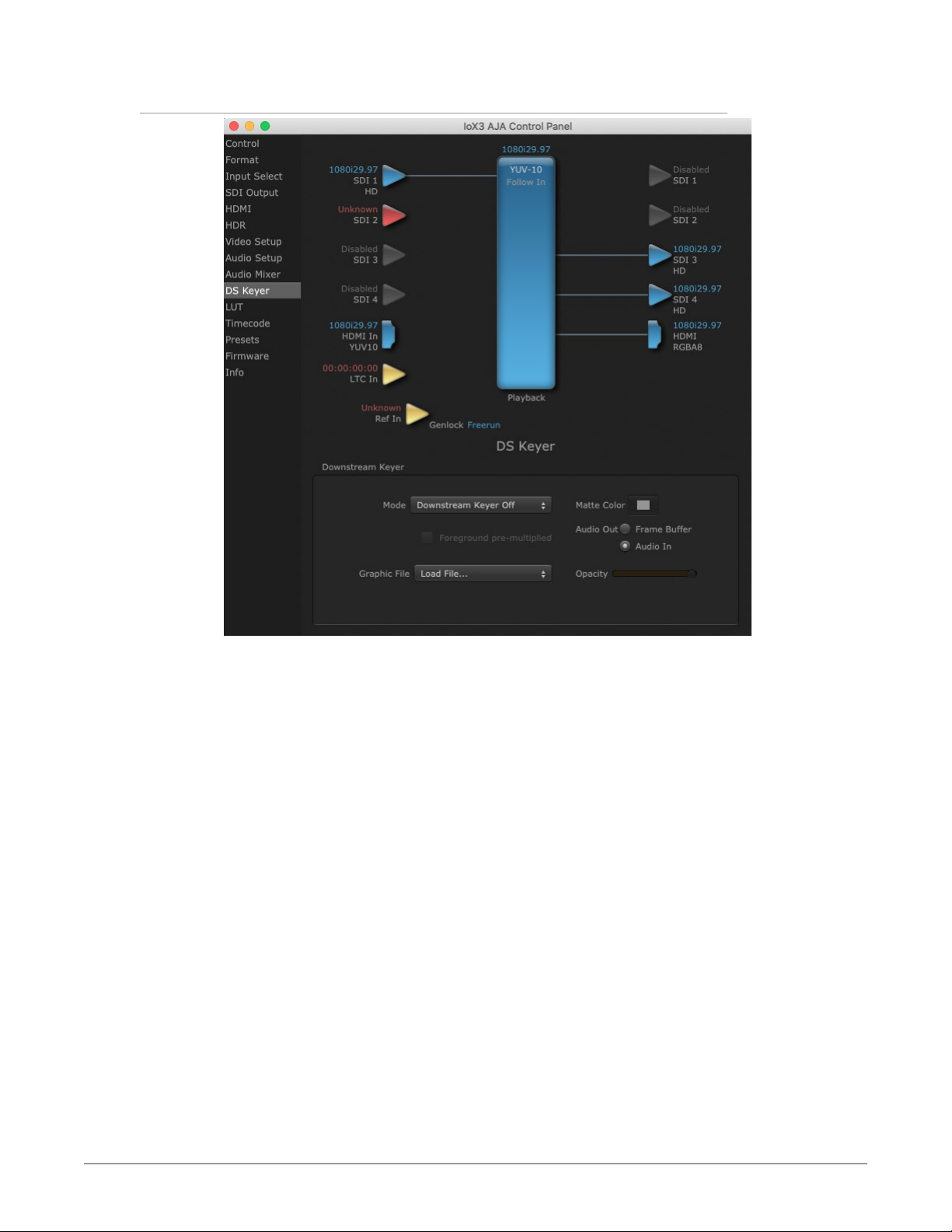
DS Keyer Screen
The Io X3 has a hardware-based downstream keyer that is ideal for putting logos,
“bugs” or other video material with an alpha channel on top of video being
played out or printed to tape.
A typical application would be putting a television station’s call letters or channel
over program video content. Keyed video can be from the Io X3 internal Frame
Buffer (from storage, video In, etc.) or from a graphics file that has an alpha
channel (Photoshop etc.).
Settings in the DS Keyer Screen provide control over how the keyer operates and
whether it’s turned on or off.
Io X3 Capture, Display, Convert v16.2 39 www.aja.com
Page 40

Mode
Downstream Keyer Off - When this pulldown menu item is selected the
downstream keyer will be turned off
• Frame Buffer over Matte - Places the keyed video with alpha channel currently
in the Frame Buffer over a fixed color matte determined by the “Matte Color”
setting set separately.
• Frame Buffer over Video In - Places the keyed video currently in the Frame
Buffer over the video input for playout or print-to-tape.
• Graphic over Matte - Places a graphics file having an alpha channel (chosen in
“Graphic File” pulldown) over a fixed color matte determined by the “Matte
Color” setting set separately.
• Graphic over Video In - Places a graphics file having an alpha channel (chosen
in “Graphic File” pulldown) over the video input for playout or print-to-tape.
• Graphic over Frame Buffer - Places a graphics file having an alpha channel
(chosen in “Graphic File” pulldown) over the current contents of the Io X3
Frame Buffer (which might be from storage, video In, etc.).
Matte Color
Only available when the pulldown “Frame Buffer over Matte” or “Graphic over
Matte” are selected-pressing this button brings up a color selection dialog. The
dialog provides a variety of ways to select a matte color including a color wheel,
color picker (choose from a location anywhere on the computer screen), numeric
sliders, swatches, “crayons”, and spectrums. The matte chosen will be used as a
video background under the keyed video.
Foreground pre-multiplied (checkbox)
Use to avoid “matte lines” and improve the appearance of the foreground (key)
being composited over the background.
Audio Out
• Frame Buffer - Select audio out to be routed from the Frame Buffer.
• Audio In - Select audio out to be routed from the Io X3’s selected input(s).
Graphic File
This pulldown allows you to choose from any recently accessed file or select a
new file (“Load File...”), which then brings up a file dialogue. You can load any
standard RGB graphics file (.tif,.psd, etc.) into the frame buffer for display, but
some graphics formats and bit depths may not be supported.
The file raster (pixel x pixel count) should match the Device Format in the frame
buffer or the secondary format if up-converting. For example, you wish to key a
logo on top of a 1920x1080 footage, the still image with alpha channel that you
load should be 1920x1080.
Loaded graphic files are retained for redisplay if another file is chosen, and even if
the Io X3 is power cycled.
NOTE: A loaded graphics file will not be scaled to fit. If it’s smaller than the current frame
buffer format,Io X3 will center it in the frame. If larger than the current frame
buffer format it will be cropped.
Io X3 Capture, Display, Convert v16.2 40 www.aja.com
Page 41
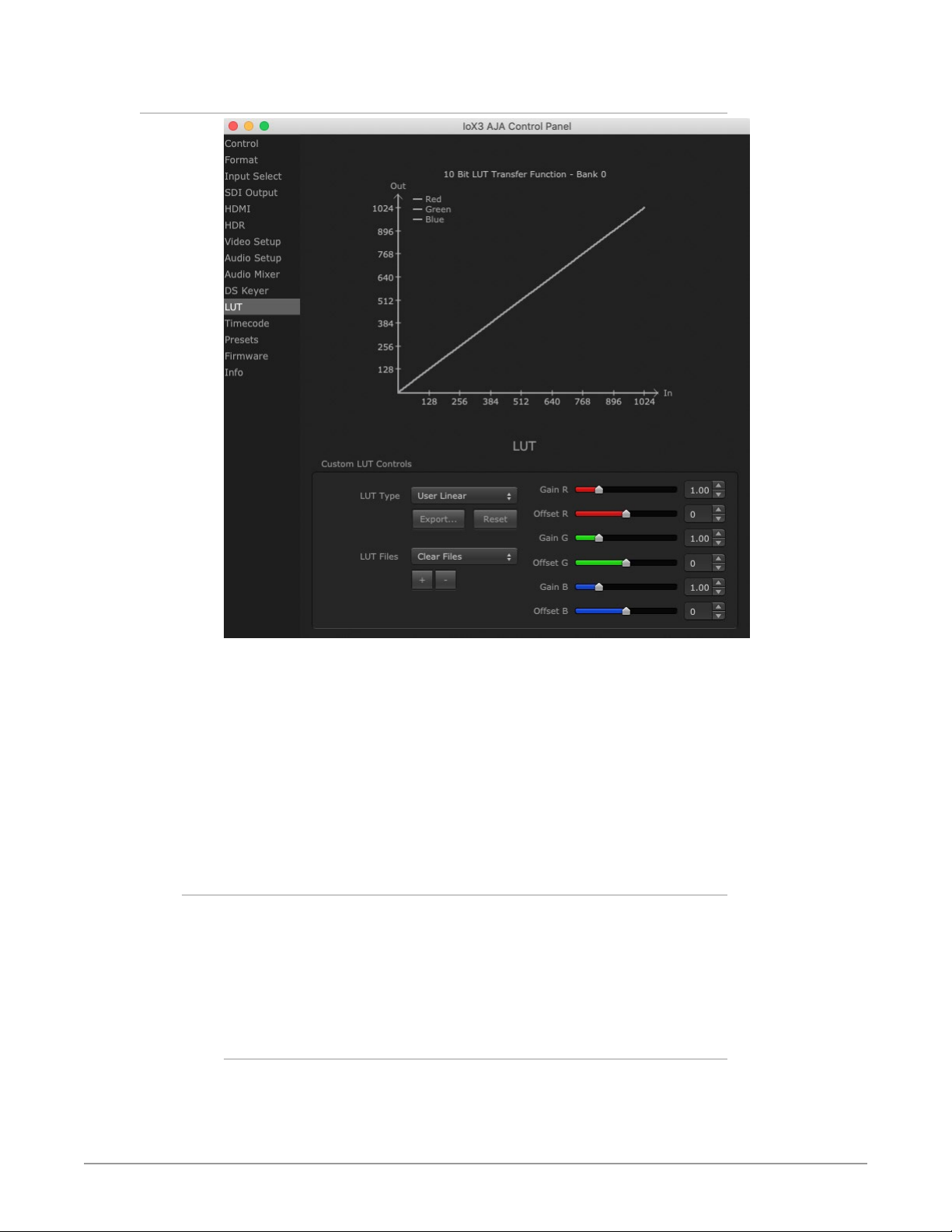
LUT Screen
The LUT screen allows you to create a custom 10-bit color look up table (LUT) on
the Io X3 output, for matching a production "look" on a specific display. These
custom LUTs can also be exported as .cube files for use with supported AJA
devices and compatible professional applications. Users can also load externally
generated LUT files into the Io X3 to ensure consistent color among different
devices.
NOTE: .cube files are the new standard for importing and exporting LUTs with AJA
Control Room as of v16.2. Prior to v16.2, Control Room supported CSV files
containing LUT information. While this LUT formatting is still supported for
import, it is no longer supported for export.
Custom LUT Controls
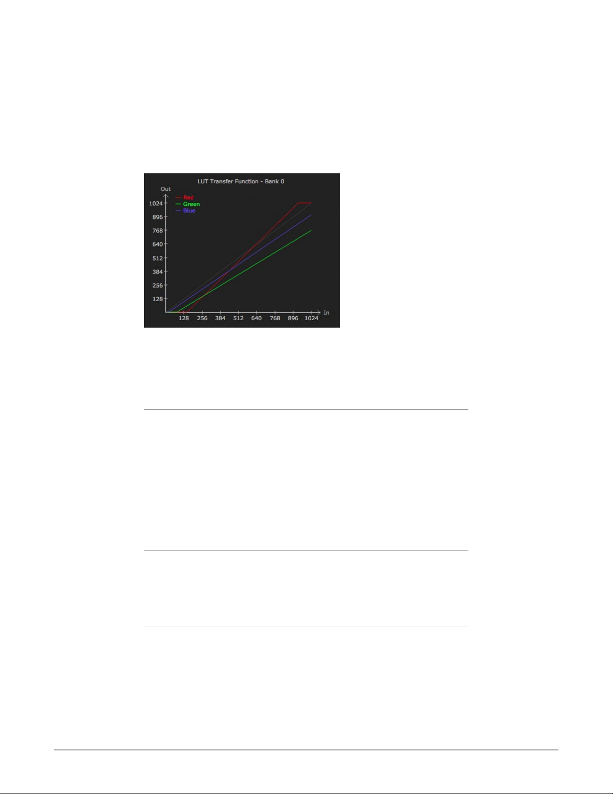
The LUT Transfer Function screen displays an approximate representation of the
effect of the current LUT settings. When the controls are activated by selecting a
User LUT Type, Red, Blue, and Green curves show the transfer functions of each
color.
NOTE: The displayed curves are approximate. Curves for some extreme settings may
diverge significantly from the actual transfer functions.
LUT Type
Selects the type of LUT. Choose from
• Auto - LUT will be automatically selected. This setting intelligently applies
the type of LUT required in the majority of use cases. For example, if the
Io X3 Capture, Display, Convert v16.2 41 www.aja.com
Page 42
Frame Buffer is set to SD 608 and the Output set to HD 709, then an industry
standard curve for changing 608 to 709 color space is applied.
• Linear - A linear 1:1 LUT is applied, resulting in no color change (every value for
source is mapped to the same value for output).
• SMPTE->FullRange - A conversion LUT from SMPTE to Full Range is applied.
• FullRange->SMPTE - A conversion LUT from Full Range to SMPTE is applied.
• User Linear - Activates the Gain and Offset controls, allowing the manual
creation of a custom LUT. Initial default setting is linear.
Figure 13. Example LUT Transfer Function Curves
• User Film Stream - Activates the Gain and Offset controls with a default curve
matching Grass Valley FilmStream cameras, and also allowing manual creation
of a custom LUT.
• User LUT File - See "LUT Files" below.
Gain and Offset Controls
When activated, the controls on the right allow adjustment of Gain and Offset for
Red, Blue and Green.
• Sliders - The sliders on the right can be used to change the values for each
color.
• Numeric Entry - You also enter a numeric value by clicking on the displayed
number, and can increase or decrease the values clicking on the up/down
arrow boxes.
• Cut and Paste - Right clicking on a displayed number opens a Cut, Copy, Paste
dropdown menu for convenient numeric entry.
Export
The Export button can be used to save the current LUT values as a .cube file.
The LUT file can be named and you can specify the location to save the file. This
Export feature lets you take the custom LUT with you and re-import it to another
system or location for consistency.
Reset
Clicking on the Reset button resets the currently selected LUT Type to its default
values (not active for a User LUT file).
Io X3 Capture, Display, Convert v16.2 42 www.aja.com
Page 43

LUT Files
The User LUT File setting above activates the LUT Files dropdown, allowing the
selection of a previously saved LUT file. You can create a custom LUT file using
most text editors or spread sheets, provided the data is arranged according to the
LUT File Format Specification that follows (see "LUT File Format Specification" on
page 43).
Uploading Custom User LUT file
Once the LUT file is created, you can upload it with the following steps:
1. Before loading a LUT, make sure you are using an RGB/RGBA frame buffer
format, and that you have a AJA Video Device that supports LUTs.
2. Open AJA Control Panel and select the “LUT” pane.
3. Click the “LUT Type” popup and choose “User LUT File” menu item. Note
“LUT Files” options become enabled.
4. Click the “+” button and use the navigation dialog to choose a custom LUT
le. The LUT is now loaded.
LUT File Format Specification
LUT files are normal text files that contain 1025 lines (numbered 0 - 1024). Each
line contains 3 integer values in the range 0 - 1023, representing 10 bit R, G, B
component output values. Component values may be separated by one or more
commas, spaces, or tabs. The example below show LUT File contents for Line 0,
Line 1, Line 2, and Line 1024, with several valid ways to separate the numbers in a
line, using comma and space, tab, or only space.
• 16, 17, 17
• 171818
• 19 19 21
• …
• 1000, 1022, 1023
In the example above, the first line (Line 0) represents the output values for the
case where R=0, G=0, or B=0. In other words, if the R component of a pixel is set
to 0, then set R component value to 16. Likewise, if G is set to 0, then set G to 17.
The second line (Line 1) does a similar thing for input component values equal to
1.
A simple way to construct a LUT file is to go to user linear in Control Panel and
make some modifications, then click export and you will have a .cube file. You can
then either import that LUT on a different workstation, or else use a text editor to
make manual adjustments if desired.
Io X3 Capture, Display, Convert v16.2 43 www.aja.com
Page 44
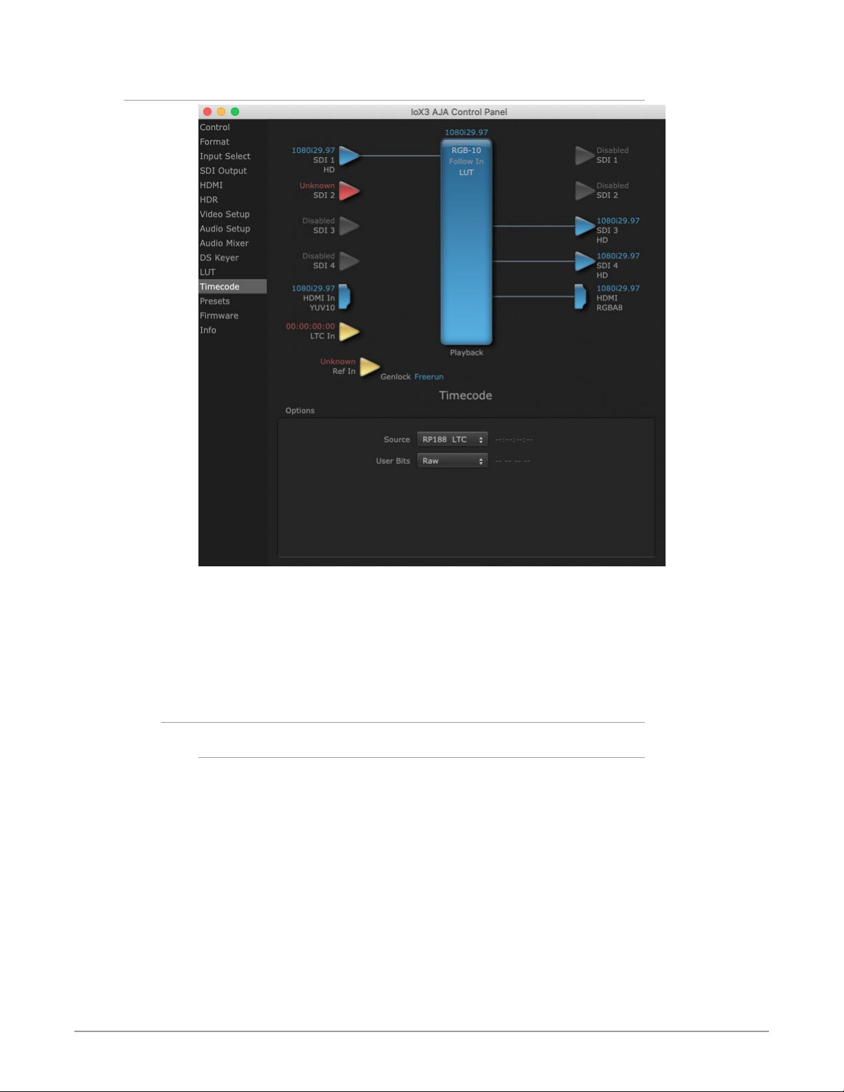
Timecode Screen
The Timecode screen is used to select the timecode stream read for applications
that use it (for example, in AJA Control Room when the Timecode Source
preference is set to “Control Panel Setting” that application will read the selected
stream). This screen is also used for monitoring the RP-188 timecode embedded
in the digital data stream, for selecting a timecode offset (if required), and setting
timecode outputs.
Options
Source
In RP-188 timecode (SMPTE 12M-gg2) there can be multiple timecode types in the
data stream. Use this pull-down to select the one you wish to monitor:
• RP188 LTC (Linear timecode)
• RP188 VITC (Vertical Interval timecode)
• LTC Port
The selection will be displayed in the timecode value displayed to the right of the
pull-down.
Io X3 Capture, Display, Convert v16.2 44 www.aja.com
Page 45
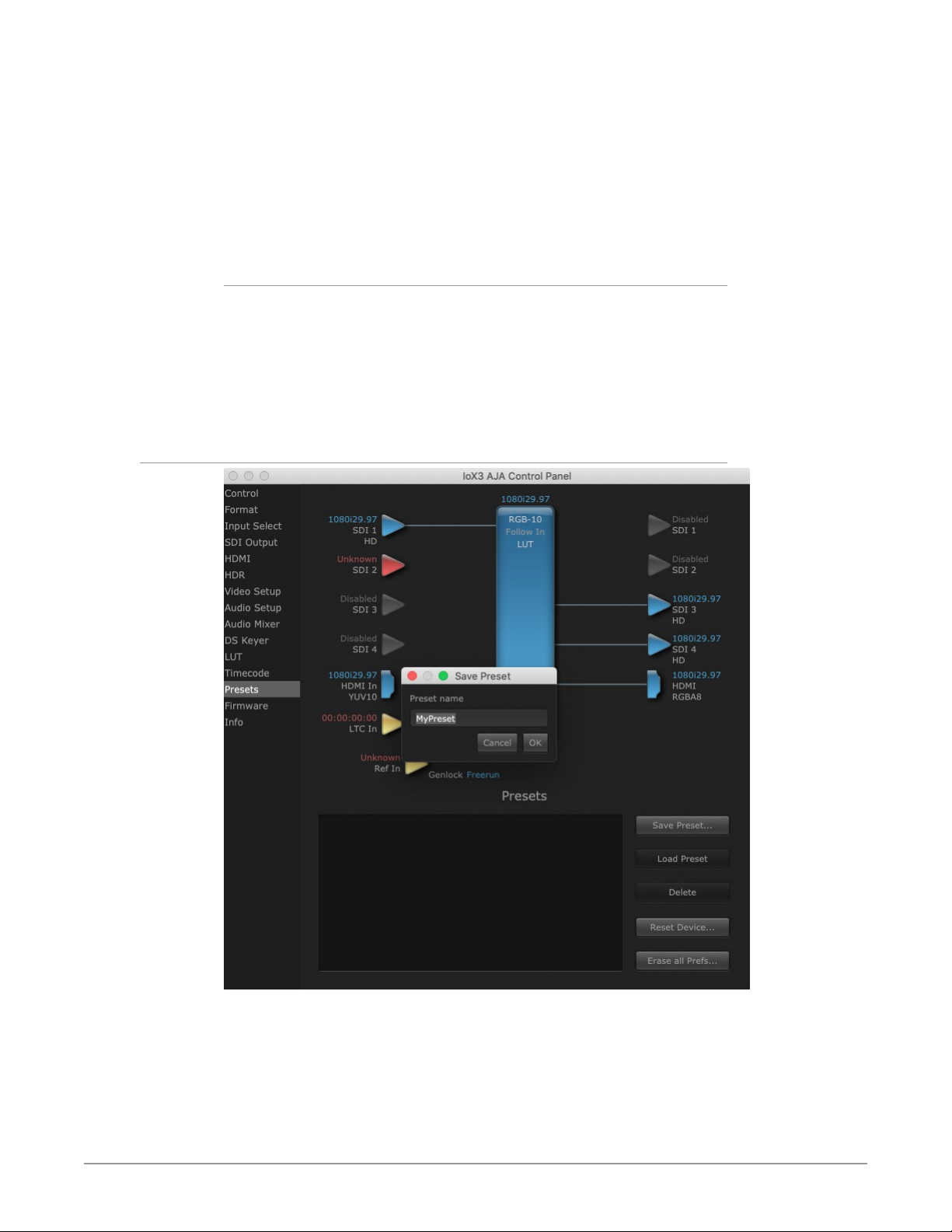
NOTE: SMPTE RP 188 defines a standard for the transmission of time code and control
code in the ancillary data space of a digital television data stream. Time code
information is transmitted in the ancillary data space as defined in ANSI/SMPTE
291M. Multiple codes can be transmitted within a single digital video data stream.
Other time information, such as real time clock, DTTR tape timer information,
and other user-defined information, may also be carried in the ancillary time
code packet instead of time code. The actual information transmitted through
the interface is identified by the coding of a distributed binary bit. Equipment
manufacturers can use the meta data for different purposes.
User Bits
For monitoring a variable framerate (VFR) timecode (such as Varicam), you may
wish to check the User-bits box. If you set this checkbox, Io X3 will detect and
interpret the user-bits and display them next to the checkbox. You will see the
original framerate (30 fps in the figure below) followed by the adjusted frame
padding (two digits reporting discarded and retained frame padding).
NOTE: SMPTE 12M-2 is the updated name and specification for what was RP-188.
Presets Screen
After configuring the AJA Control Panel screens, you can then save all your
settings as a snapshot for later recall, called a preset. In this way, you can organize
presets for all your typical tasks, eliminating manual reconfiguration.
Io X3 Capture, Display, Convert v16.2 45 www.aja.com
Page 46

Saving, Loading and Deleting Presets
To save a preset, simply go to the Presets screen and click “Save Preset”. A dialog
will be presented asking you for a file name. Enter a meaningful name and click
“OK”. Thereafter the preset will be available under the Control Panel “Presets” list.
From the Presets screen you can manage your collection of presets easily. To Load
or Delete a stored preset, just select it with your mouse and then click the “Load
Preset” or “Delete” button respectively .
Transferring Saved Presets
If you want to use a saved Preset on another workstation, you can simply copy
the file on removable storage and install it at the new location. The Preset files are
stored at:
Mac OS Preset Files Storage Location
• From the Finder, hold down the Option key (to display the Library directory)
and click on Go/Library/Application Support/AJA/<device name>/Presets/
Windows Preset Files Storage Location
• c:\Users\<username>\AppData\Local\AJA\Control Panel\<device name>
Presets\
Reset to Default
When you click the "Reset Device" button the Default User Preference file will be
deleted and AJA Control Panel will do one of the following:
• If a Default Global Preference if found, it is loaded and the device is set to this
state.
• If a Default Global Preference file is not found, “factory defaults” are loaded
and the device is set to this state.
NOTE: See "Default Preferences" on page 16 for more information.
Erase all Prefs
For technical support purposes you may be required to remove the current
Preference settings. Clicking on the "Erase all Prefs" button deletes the current
Default User Preference file without accessing a Default Global Preference file, if
one exists. Current AJA device settings are not altered, but changing any setting
will immediately regenerate a Default Use Preference file with the changed
settings.
NOTE: Clicking on the AJA Control Panel Erase All Prefs button does NOT delete an
existing Global Preference file from that shared location.
Io X3 Capture, Display, Convert v16.2 46 www.aja.com
Page 47
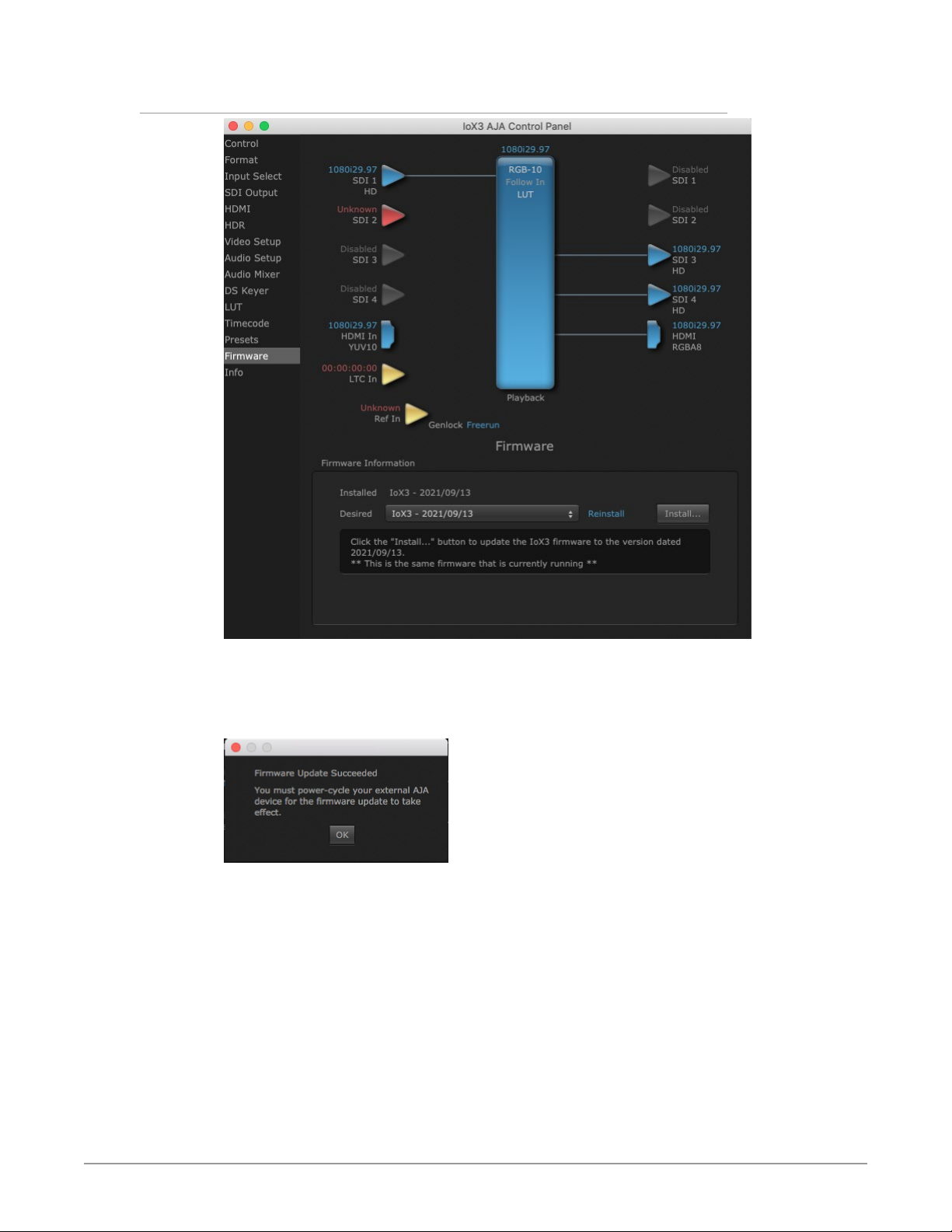
Firmware Screen
Use the Firmware screen to access the firmware install screen. Click install to erase
current firmware and load the firmware version contained in your current driver
installation. Note the Installation message shown below.
Figure 14. Update Completed
You will be required to power-cycle your Io X3 and computer to finish the update.
Io X3 Capture, Display, Convert v16.2 47 www.aja.com
Page 48
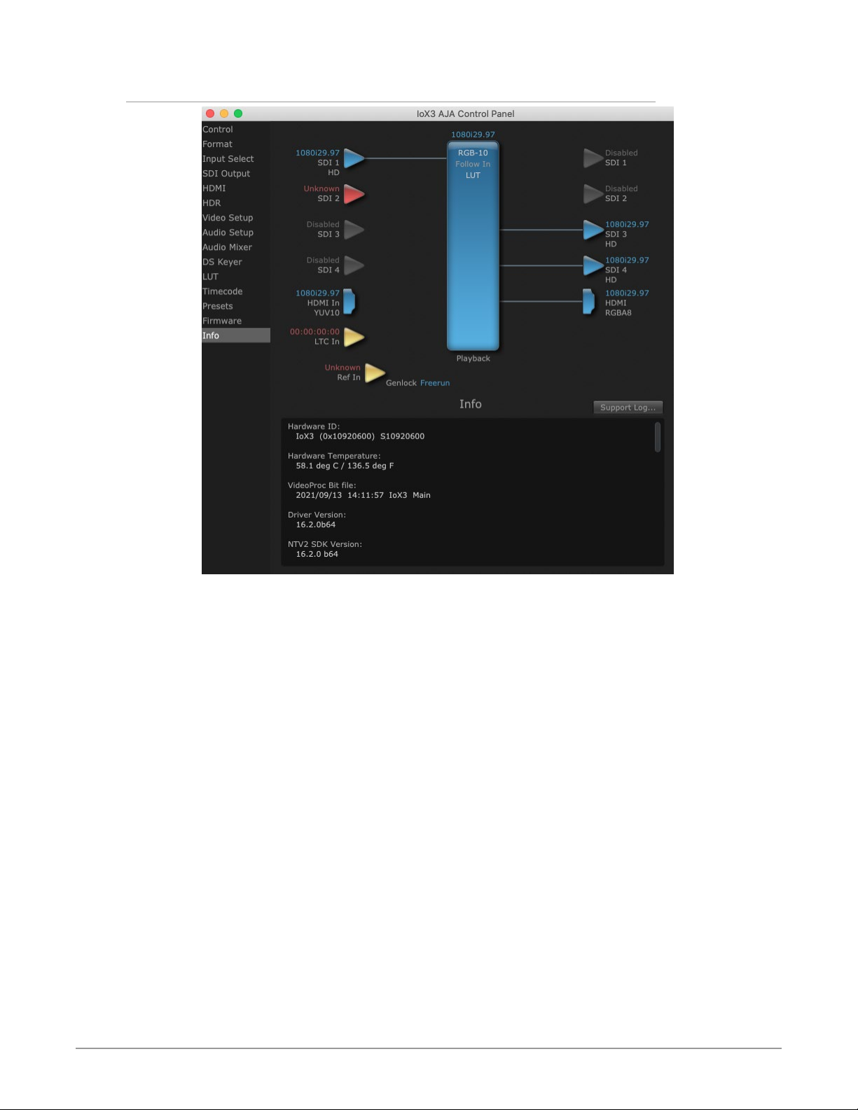
Info Screen
The Info Screen shows the software files that have been installed on your
system. This information may be needed if you talk to an AJA Customer Service
representative to determine if files are missing or need updating.
Io X3 Capture, Display, Convert v16.2 48 www.aja.com
Page 49

Appendix A – Specifications
Io X3 Tech Specs
Video Formats
• (2K) 2048 x 1080p 23.98, 24, 25, 29.97, 30, 47.95, 48, 50, 59.94, 60
• (2K) 2048 x 1080PsF 23.98, 24, 25
• (HD) 1080p 23.98, 24, 25, 29.97, 30, 50, 59.94, 60
• (HD) 1080PsF 23.98, 24, 25, 29.97, 30
• (HD) 1080i 50, 59.94, 60
• (HD) 720p 50, 59.94, 60
• (SD) 625i 50
• (SD) 525i 59.94
Note: High Frame Rate support is dependent on Thunderbolt speed and system
performance. Not all host systems will support all frame rates.
Video Input Digital
• 3G-SDI, SMPTE 425
• RGB 4:4:4 12-bit*, YCbCr 4:2:2 10-bit
• 1.5G-SDI, SMPTE 292M
• Single Link HD-SDI YCbCr 4:2:2 10-bit
• 270 Mbps SDI, SMPTE 259M-C
• YCbCr 4:2:2 10-bit, 8-bit
• HDMI v1.4b
• 30/36-bits/pixel, RGB or YUV, 2.25 Gbps
• 2K, HD, and SD
*Bit depth support is application dependent. Check with your software
manufacturer for compatibility.
Video Output Digital
• 3G-SDI, SMPTE 425
• RGB 4:4:4 12-bit*, YCbCr 4:2:2 10-bit
• 1.5G-SDI, SMPTE 292M
• Single Link HD-SDI YCbCr 4:2:2 10-bit
• 270 Mbps SDI, SMPTE 259M-C
• YCbCr 4:2:2 10-bit, 8-bit
• HDMI v1.4b
• 30/36-bits/pixel, RGB or YUV, 2.25 Gbps
• 2K, HD, and SD
*Bit depth support is application dependent. Check with your software
manufacturer for compatibility.
HDR
• SDI: VPID signaling for SDR/HDR Transfer Characteristics
• HDMI: HDR10 Support - HDR Infoframe metadata, compatible with HDMI 2.0a/
CTA- 861.3
• HDMI: HLG Support - compatible with HDMI 2.0b/CTA-861-G
Io X3 Capture, Display, Convert v16.2 49 www.aja.com
Page 50

Note: HDR support is application dependent. Check with your software
manufacturer for compatibility.
Audio Input Digital
• 16-channel, 16 and 24-bit SMPTE-259 SDI embedded audio, 48 kHz sample
rate, synchronous
• 8-channel, 16 and 24-bit HDMI embedded audio, 48 kHz sample rate,
synchronous
Audio Output Digital
• 16-channel, 16 and 24-bit SMPTE-259 SDI embedded audio, 48 kHz sample
rate, synchronous
• 8-channel, 16 and 24-bit HDMI embedded audio, 48 kHz sample rate,
synchronous
Audio Input Analog
• 8-channel, 24 and 16-bit D/A analog audio, 48 kHz sample rate, balanced,
using industry standard 8x XLR on DB-25 breakout cable (cable not included)
• +24 dBu full scale digital (0 dBFS)
• +/- 0.2 dB 20 to 20 kHz frequency response
• Input supported across Ch 1-8, Ch 1-4, or Ch 5-8 depending on configuration
chosen
Audio Output Analog
• 8-channel, 24-bit D/A analog audio, 48 kHz sample rate, balanced, using
industry standard 8x XLR on DB-25 breakout cable (cable not included)
• +24 dBu full scale digital (0 dBFS)
• +/- 0.2 dB 20 to 20 kHz frequency response
• Output supported across Ch 1-8, Ch 1-4, or Ch 5-8 depending on
configuration chosen
• 2-channel, 18-bit D/A analog audio, 48 kHz sample rate, unbalanced, using
standard 3.5mm jack
• 1.2V RMS full scale digital output level (0 dBFS)
Downstream Keyer
• Supports graphics up to 2K/HD with alpha channel over video, matte or
framebuffer, or framebuffer content over incoming video or matte
LTC
• 1x BNC LTC input (dedicated)
• 1x BNC LTC output (dedicated)
Reference
• 1x BNC (dedicated)
• Analog Color Black (1V) or Composite Sync (2 or 4V)
• Nonterminating
Electrical Interface
• Thunderbolt 3 (2x)
Io X3 Capture, Display, Convert v16.2 50 www.aja.com
Page 51
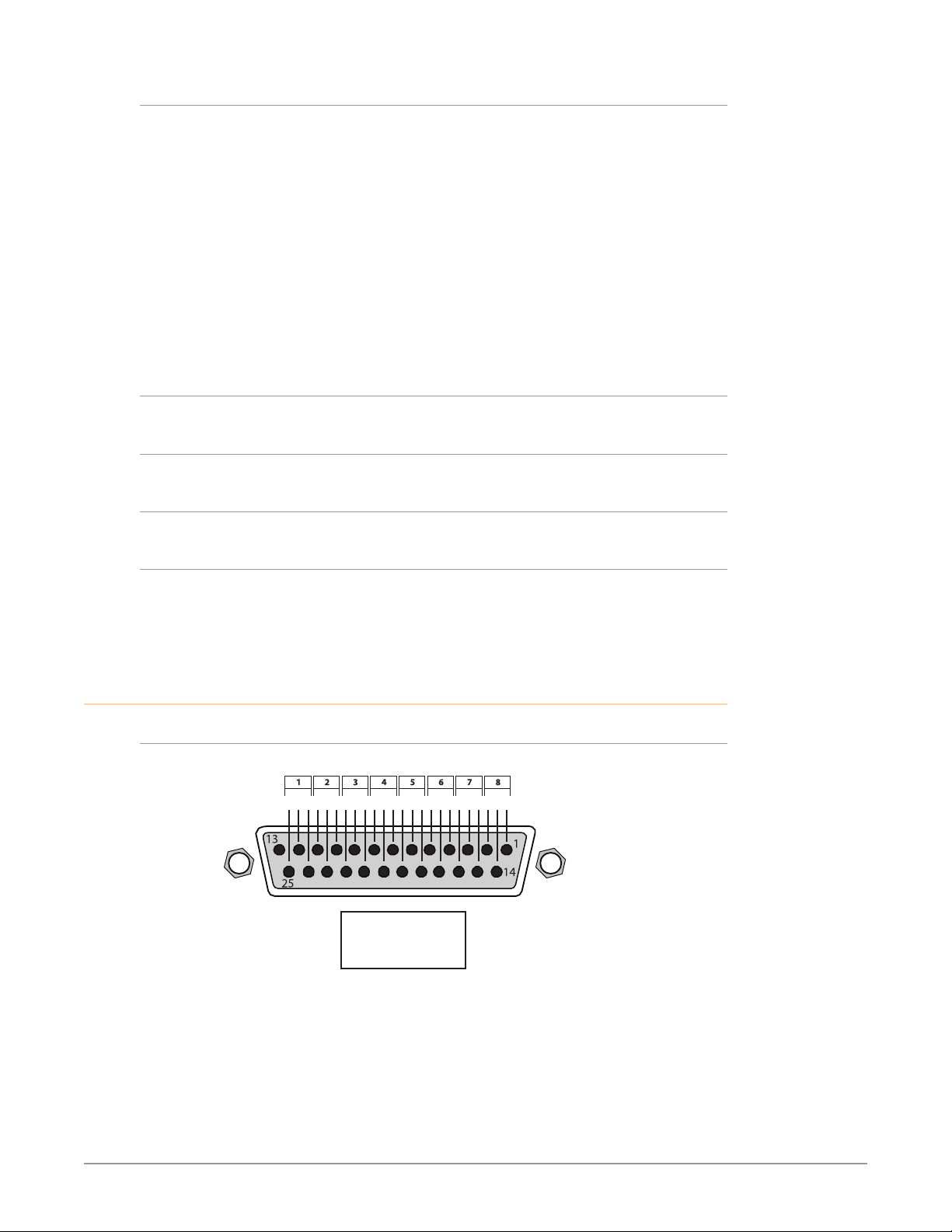
Machine Control
• RS-422, Sony 9-pin protocol
• 9-pin D-connector pinout is as follows:
• 1 GND
• 2 RX-
• 3 T X+
• 4 GND
• 5 No Connection
• 6 GND
• 7 RX+
• 8 TX-
• 9 GND
• Shell GND
Size (w x d x h)
• 8.74" x 7.09" x 1.65" (222.0 x 180.09 x 41.91 mm)
Weight
• 3.1 lbs. (1.5 kg)
Power
• 10-20V, 23W typical, 28W max
Environment
• Safe Operating Temperature Range: 0 to 35 C (32 to 95 F)
• Safe Storage Temperature (Power OFF): -40 to 60 C (-40 to 140 F)
• Operating Relative Humidity: 10-90% noncondensing
• Operating Altitude: <3,000 meters (<10,000 feet)
Audio Connection Pinouts
Analog Audio
Figure 15. DB-25 Analog Audio Connector Pinouts
G - +G - +G - +G - +G - +G - +G - +G - +
Key
G = Ground
+/- = Balanced Pair
Io X3 Capture, Display, Convert v16.2 51 www.aja.com
Page 52

Appendix B – Safety and Compliance
Federal Communications Commission (FCC) Compliance Notices
Class A Interference Statement
This equipment has been tested and found to comply with the limits for a Class
A digital device, pursuant to Part 15, Subpart B of the FCC Rules. These limits
are designed to provide reasonable protection against harmful interference
in a residential installation. This equipment generates, uses, and can radiate
radio frequency energy and, if not installed and used in accordance with the
instructions, may cause harmful interference to radio communications. However,
there is no guarantee that interference will not occur in a particular installation. If
this equipment does cause harmful interference to radio or television reception,
which can be determined by turning the equipment off and on, the user is
encouraged to try to correct the interference by one or more of the following
measures:
• Reorient or relocate the receiving antenna.
• Increase the separation between the equipment and receiver.
• Connect the equipment into an outlet on a circuit different from that to which
the receiver is connected.
• Consult the dealer or an experienced radio/TV technician for help.
FCC Caution
This device complies with Part 15 of the FCC Rules. Operation is subject to the
following two conditions: (1) This device may not cause harmful interference, and
(2) this device must accept any interference received, including interference that
may cause undesired operation.
Canadian ICES Statement
Canadian Department of Communications Radio Interference Regulations
This digital apparatus does not exceed the Class A limits for radio-noise emissions
from a digital apparatus as set out in the Radio Interference Regulations of
the Canadian Department of Communications. This Class A digital apparatus
complies with Canadian ICES-003.
Règlement sur le brouillage radioélectrique du ministère des Communications
Cet appareil numérique respecte les limites de bruits radioélectriques visant les
appareils numériques de classe A prescrites dans le Règlement sur le brouillage
radioélectrique du ministère des Communications du Canada. Cet appareil
numérique de la Classe A est conforme à la norme NMB-003 du Canada.
European Union and European Free Trade Association (EFTA)
Regulatory Compliance
This equipment may be operated in the countries that comprise the member
countries of the European Union and the European Free Trade Association. These
countries, listed in the following paragraph, are referred to as The European
Community throughout this document:
AUSTRIA, BELGIUM, BULGARIA, CYPRUS, CZECH REPUBLIC, DENMARK, ESTONIA,
FINLAND, FRANCE, GERMANY, GREECE, HUNGARY, IRELAND, ITALY, LATVIA,
LITHUANIA, LUXEMBOURG, MALTA, NETHERLANDS, POLAND, PORTUGAL,
ROMANIA, SLOVAKIA, SLOVENIA, SPAIN, SWEDEN, UNITED KINGDOM, ICELAND,
LICHTENSTEIN, NORWAY, SWITZERLAND
Io X3 Capture, Display, Convert v16.2 52 www.aja.com
Page 53
Declaration of Conformity
Marking by this symbol indicates compliance with the Essential Requirements of
the EMC Directive of the European Union 2014/30/EU.
This equipment meets the following conformance standards:
Safety
EN 62368-1: 2014 + A11 (T-Mark License),
IEC 62368-1: 2014 (CB Scheme Certificate)
Additional licenses issued for specific countries available on request.
Emissions
EN 55032: 2015, CISPR 32: 2015
EN 61000-3-2: 2014, EN 61000-3-3: 2013
Immunity
EN 55103-2: 2009
61000-4-2: 2009, EN 61000-4-3: 2006 + A1: 2008 + A2: 2010,
EN 61000-4-4: 2012, EN 61000-4-5: 2014 + A1: 2017, EN 61000-4-6: 2013,
EN 61000-4-11: 2020
Environments: E2, E3 and E4
The product is also licensed for additional country specific standards as required
for the International Marketplace.
Warning! This is a Class A product. In a domestic environment, this product
may cause radio interference, in which case, the user may be required to take
appropriate measures.
Achtung! Dieses ist ein Gerät der Funkstörgrenzwertklasse A. In Wohnbereichen
können bei Betrieb dieses Gerätes Rundfunkstörungen auftreten, in welchen
Fällen der Benutzer für entsprechende Gegenmaßnahmen verantwortlich ist.
Attention! Ceci est un produit de Classe A. Dans un environnement domestique,
ce produit risque de créer des interférences radioélectriques, il appartiendra
alors à l?utilisateur de prendre les mesures spécifiques appropriées..
Recycling Notice
This symbol on the product or its packaging indicates that this product
must not be disposed of with your other household waste. Instead, it is your
responsibility to dispose of your waste equipment by handing it over to a
designated collection point for the recycling of waste electrical and electronic
equipment. The separate collection and recycling of your waste equipment
at the time of disposal will help conserve natural resources and ensure that
it is recycled in a manner that protects human health and the environment.
For more information about where you can drop off your waste for recycling,
please contact your local authority, or where you purchased your product.
Korea KCC Compliance Statement
ꩡ 끞 녅 껽 驩 ꓭ
넩 韥韥鱉 꽺ꓩ끞 쀍陲꾅 ꩡ끞뼕 ꑞ놶냱ꈑ 놶뼞ꫦ뵾閵ꌱ ꗐ냵 韥韥ꈑ 閵뇊
끞 쀍陲꾅 ꩡ끞뼍鱉 陲끥 놹볁閹ꫢ넍 끥ꇙ閵 넽걪鱽鲙.
Io X3 Capture, Display, Convert v16.2 53 www.aja.com
Page 54
Taiwan Compliance Statement
This is a Class A product based on the standard of the Bureau of Standards,
Metrology and Inspection (BSMI) CNS 13438, Class A. In a domestic environment
this product may cause radio interference in which case the user may be required
to take adequate measures.
Japan Compliance Statement
This is a Class A product based on the standard of the VCCI Council (VCCI32:2016).
If this equipment is used in a domestic environment, radio interference may
occur, in which case, the user may be required to take corrective actions.
Translated Warning and Caution Messages
The following caution statements, warning conventions, and warning messages
apply to this product and manual.
Before Operation Please Read These Instructions
Warning! Read and follow all warning notices and instructions marked on the
product or included in the documentation.
Avertissement! Lisez et conformez-vous à tous les avis et instructions
d'avertissement indiqués sur le produit ou dans la documentation.
Warnung! Lesen und befolgen Sie die Warnhinweise und Anweisungen, die auf
dem Produkt angebracht oder in der Dokumentation enthalten sind.
¡Advertencia! Lea y siga todas las instrucciones y advertencias marcadas en el
producto o incluidas en la documentación.
Aviso! Leia e siga todos os avisos e instruções assinalados no produto ou incluídos
na documentação.
Avviso! Leggere e seguire tutti gli avvisi e le istruzioni presenti sul prodotto o
inclusi nella documentazione.
Io X3 Capture, Display, Convert v16.2 54 www.aja.com
Page 55
Warning! Do not use this device near water and clean only with a dry cloth.
Avertissement! N'utilisez pas cet appareil près de l'eau et nettoyez-le seulement
avec un tissu sec.
Warnung! Das Gerät nicht in der Nähe von Wasser verwenden und nur mit einem
trockenen Tuch säubern.
¡Advertencia! No utilice este dispositivo cerca del agua y límpielo solamente con
un paño seco.
Aviso! Não utilize este dispositivo perto da água e limpe-o somente com um pano
seco.
Avviso! Non utilizzare questo dispositivo vicino all'acqua e pulirlo soltanto con un
panno asciutto.
Warning! Do not block any ventilation openings. Install in accordance with the
manufacturer's instructions.
Avertissement! Ne bloquez aucune ouverture de ventilation. Suivez les
instructions du fabricant lors de l'installation.
Warnung! Die Lüftungsöffnungen dürfen nicht blockiert werden. Nur gemäß den
Anweisungen des Herstellers installieren.
¡Advertencia! No bloquee ninguna de las aberturas de la ventilación. Instale de
acuerdo con las instrucciones del fabricante.
Aviso! Não obstrua nenhuma das aberturas de ventilação. Instale de acordo com as
instruções do fabricante.
Avviso! Non ostruire le aperture di ventilazione. Installare in conformità con le
istruzioni del fornitore.
Warning! Do not install near any heat sources such as radiators, heat registers,
stoves, or other apparatus (including amplifiers) that produce heat.
Avertissement! N'installez pas l'appareil près d'une source de chaleur telle que des
radiateurs, des bouches d'air de chauffage, des fourneaux ou d'autres appareils
(amplificateurs compris) qui produisent de la chaleur.
Warnung! Nicht in der Nähe von Wärmequellen wie Heizkörpern, Heizregistern,
Öfen oder anderen Wärme erzeugenden Geräten (einschließlich Verstärkern)
aufstellen.
¡Advertencia! No instale cerca de fuentes de calor tales como radiadores, registros
de calor, estufas u otros aparatos (incluidos amplificadores) que generan calor.
Aviso! Não instale perto de nenhuma fonte de calor tal como radiadores, saídas
de calor, fogões ou outros aparelhos (incluindo amplificadores) que produzam
calor.
Avviso! Non installare vicino a fonti di calore come termosifoni, diffusori di aria
calda, stufe o altri apparecchi (amplificatori compresi) che emettono calore
Warning! Unplug this device during lightning storms or when unused for long
periods of time.
Avertissement! Débranchez cet appareil pendant les orages avec éclairsou s'il est
inutilisé pendant de longues périodes.
Warnung! Das Gerät ist bei Gewitterstürmen oder wenn es über lange Zeiträume
ungenutzt bleibt vom Netz zu trennen.
¡Advertencia! Desenchufe este dispositivo durante tormentas eléctricas o cuando
no se lo utilice por largos periodos del tiempo.
Aviso! Desconecte este dispositivo da tomada durante trovoadas ou quando não é
utilizado durante longos períodos de tempo.
Avviso! Utilizzare soltanto i collegamenti e gli accessori specificati e/o venduti dal
produttore, quali il treppiedi e l'esoscheletro.
Io X3 Capture, Display, Convert v16.2 55 www.aja.com
Page 56
Warning! Do not open the chassis. There are no user-serviceable parts inside.
Opening the chassis will void the warranty unless performed by an AJA service
center or licensed facility.
Avertissement! Ne pas ouvrir le châssis. Aucun élément à l’intérieur du châssis
ne peut être réparé par l’utilisateur. La garantie sera annulée si le châssis est
ouvert par toute autre personne qu’un technicien d’un centre de service ou d’un
établissement agréé AJA.
Warnung! Öffnen Sie das Gehäuse nicht. Keine der Geräteteile können vom
Benutzer gewartet werden. Durch das Öffnen des Gehäuses wird die Garantie
hinfällig, es sei denn, solche Wartungsarbeiten werden in einem AJA-ServiceCenter oder einem lizenzierten Betrieb vorgenommen.
¡Advertencia! No abra el chasis. El interior no contiene piezas reparables por el
usuario. El abrir el chasis anulará la garantía a menos que se lo haga en un centro
de servicio AJA o en un local autorizado.
Advertência! Não abra o chassi. Não há internamente nenhuma peça que permita
manutenção pelo usuário. Abrir o chassi anula a garantia, a menos que a abertura
seja realizada por uma central de serviços da AJA ou por um local autorizado.
Avvertenza! Non aprire lo chassis. All’interno non ci sono parti riparabili
dall’utente. L’apertura dello chassis invaliderà la garanzia se non viene effettuata
da un centro ufficiale o autorizzato AJA.
Warning! Only use attachments and accessories specified and/or sold by the
manufacturer.
Avertissement! Utilisez seulement les attaches et accessoires spécifiés et/ou
vendus par le fabricant.
Warnung! Verwenden Sie nur Zusatzgeräte und Zubehör angegeben und / oder
verkauft wurde durch den Hersteller.
¡Advertencia! Utilice solamente los accesorios y conexiones especificados y/o
vendidos por el fabricante.
Aviso! Utilize apenas equipamentos/acessórios especificados e/ou vendidos pelo
fabricante.
Avviso! Utilizzare soltanto i collegamenti e gli accessori specificati e/o venduti dal
produttore.
Io X3 Capture, Display, Convert v16.2 56 www.aja.com
Page 57

Warning! Refer all servicing to qualified service personnel. Servicing is required
when the device has been damaged in any way, such as power-supply cord or
plug is damaged, liquid has been spilled or objects have fallen into the device,
the device has been exposed to rain or moisture, does not operate normally, or
has been dropped.
Avertissement! Référez-vous au personnel de service qualifié pour tout entretien.
L'entretien est exigé quand l'appareil a été endommagé de quelque manière
que ce soit, par exemple lorsque le cordon d'alimentation ou la prise sont
endommagés, que du liquide a été versé ou des objets sont tombés dans
l'appareil, que l'appareil a été exposé à la pluie ou à l'humidité, ne fonctionne pas
normalement ou est tombé.
Warnung! Das Gerät sollte nur von qualifizierten Fachkräften gewartet werden.
Eine Wartung ist fällig, wenn das Gerät in irgendeiner Weise beschädigt wurde,
wie bei beschädigtem Netzkabel oder Netzstecker, falls Flüssigkeiten oder
Objekte in das Gerät gelangen, das Gerät Regen oder Feuchtigkeit ausgesetzt
wurde, nicht ordnungsgemäß funktioniert oder fallen gelassen wurde.
¡Advertencia! Consulte al personal calificado por cuestiones de reparación. El
servicio de reparación se requiere cuando el dispositivo ha recibido cualquier
tipo de daño, por ejemplo cable o espigas dañadas, se ha derramado líquido o
se han caído objetos dentro del dispositivo, el dispositivo ha sido expuesto a la
lluvia o humedad, o no funciona de modo normal, o se ha caído.
Aviso! Remeta todos os serviços de manutenção para o pessoal de assistência
qualificado. A prestação de serviços de manutenção é exigida quando o
dispositivo foi danificado mediante qualquer forma, como um cabo de
alimentação ou ficha que se encontra danificado/a, quando foi derramado
líquido ou caíram objectos sobre o dispositivo, quando o dispositivo foi exposto
à chuva ou à humidade, quando não funciona normalmente ou quando foi
deixado cair.
Avviso! Fare riferimento al personale qualificato per tutti gli interventi di assistenza.
L'assistenza è necessaria quando il dispositivo è stato danneggiato in qualche
modo, ad esempio se il cavo di alimentazione o la spina sono danneggiati, è
stato rovesciato del liquido è stato rovesciato o qualche oggetto è caduto nel
dispositivo, il dispositivo è stato esposto a pioggia o umidità, non funziona
correttamente o è caduto
Io X3 Capture, Display, Convert v16.2 57 www.aja.com
Page 58
Warning! Do not defeat the safety purpose of the polarized or grounding-
type plug. A polarized plug has two blades with one wider than the other. A
grounding type plug has two blades and a third grounding prong. The wide
blade or the third prong are provided for your safety. If the provided plug does
not fit into your outlet, consult an electrician for replacement of the obsolete
outlet.
Avertissement! La sécurité de la prise polarisée ou de la prise de type mise à la
terre ne doit en aucun cas être empêchée de fonctionner. Une prise polarisée
a deux broches, l'une étant plus large que l'autre. Une prise de type mise à la
terre a deux broches et une troisième broche pour la mise à la terre. La broche
large ou la troisième broche sont fournies pour votre sécurité. Si la prise
fournie ne s'insère pas dans votre prise femelle, consultez un électricien pour le
remplacement de la prise femelle obsolète.
Warnung! Der Sicherheitszweck des gepolten bzw. Schukosteckers ist zu
berücksichtigen. Ein gepolter Stecker verfügt über zwei Pole, von denen einer
breiter als der andere ist. Ein Schukostecker verfügt neben den zwei Polen noch
über einen dritten Pol zur Erdung. Der breite Pol bzw. der Erdungspol dienen der
Sicherheit. Wenn der zur Verfügung gestellte Stecker nicht in Ihren Anschluss
passt, konsultieren Sie einen Elektriker, um den veralteten Anschluss zu ersetzen.
¡Advertencia! No eche por tierra la finalidad del tipo de enchufe polarizado con
conexión a tierra. Un enchufe polarizado tiene dos espigas, una más ancha
que la otra. Un enchufe con conexión a tierra tiene dos espigas iguales y una
tercera espiga que sirve para la conexión a tierra. La expiga ancha, o la tercera
espiga, sirven para su seguridad. Si el enchufe suministrado no encaja en el
tomacorriente, consulte con un electricista para reemplazar el tomacorriente
obsoleto.
Aviso! Não anule a finalidade da segurança da ficha polarizada ou do tipo ligação
terra. Uma ficha polarizada tem duas lâminas sendo uma mais larga do que
a outra. Uma ficha do tipo de ligação à terra tem duas lâminas e um terceiro
terminal de ligação à terra. A lâmina larga ou o terceiro terminal são fornecidos
para sua segurança. Se a ficha fornecida não couber na sua tomada, consulte um
electricista para a substituição da tomada obsoleta.
Avviso! Non compromettere la sicurezza della spina polarizzata o con messa a
terra. Una spina polarizzata ha due spinotti, di cui uno più largo. Una spina con
messa a terra ha due spinotti e un terzo polo per la messa a terra. Lo spinotto
largo o il terzo polo sono forniti per motivi di sicurezza. Se la spina fornita non
si inserisce nella presa di corrente, contattare un elettricista per la sostituzione
della presa obsoleta.
Warning! Disconnect the external AC power supply line cord(s) from the mains
power before moving the unit.
Avertissement! Retirez le ou les cordons d’alimentation en CA de la source
d’alimentation principale lorsque vous déplacez l’appareil.
Warnung! Trennen Sie die Wechselstrom-Versorgungskabel vom Netzstrom, bevor
Sie das Gerät verschieben.
¡Advertencia! Cuando mueva la unidad desenchufe de la red eléctrica el/los
cable(s) de la fuente de alimentación CA tipo brick.
Advertência! Remova os cabos CA de alimentação brick da rede elétrica ao mover
a unidade.
Avvertenza! Scollegare il cavo dell’alimentatore quando si sposta l’unità.
Io X3 Capture, Display, Convert v16.2 58 www.aja.com
Page 59
Warning! Since the Mains plug is used as the disconnection for the device, it must
remain readily accessible and operable.
Avertissement! Puisque la prise principale est utilisée pour débrancher l'appareil,
elle doit rester aisément accessible et fonctionnelle.
Warnung! Da der Netzstecker als Trennvorrichtung dient, muss er stets zugänglich
und funktionsfähig sein.
¡Advertencia! Puesto que el enchufe de la red eléctrica se utiliza como dispositivo
de desconexión, debe seguir siendo fácilmente accesible y operable.
Aviso! Dado que a ficha principal é utilizada como a desconexão para o dispositivo,
esta deve manter-se prontamente acessível e funcional.
Avviso! Poiché il cavo di alimentazione viene usato come dispositivo di
sconnessione, deve rimane prontamente accessibile e operabile.
Warning! Protect the power cord from being walked on or pinched particularly at
plugs, convenience receptacles, and the point where they exit from the device.
Avertissement! Protégez le cordon d'alimentation pour que l'on ne marche
pas dessus ou qu'on le pince, en particulier au niveau des prises mâles, des
réceptacles de convenance, et à l'endroit où il sort de l'appareil.
Warnung! Vermeiden Sie, dass auf das Netzkabel getreten oder das Kabel geknickt
wird, insbesondere an den Steckern, den Steckdosen und am Kabelausgang am
Gerät.
¡Advertencia! Proteja el cable de energía para que no se le pise ni apriete, en
especial cerca del enchufe, los receptáculos de conveniencia y el punto del que
salen del equipo.
Aviso! Proteja o cabo de alimentação de ser pisado ou de ser comprimido
particularmente nas fichas, em tomadas de parede de conveniência e no ponto
de onde sai do dispositivo.
Avviso! Proteggere il cavo di alimentazione in modo che nessuno ci cammini sopra
e che non venga schiacciato soprattutto in corrispondenza delle spine e del
punto in cui esce dal dispositivo.
Io X3 Capture, Display, Convert v16.2 59 www.aja.com
Page 60

Warranty and Liability Information
Limited Warranty on Hardware
AJA Video Systems, Inc. (AJA Video) warrants that the hardware product, not
including storage modules or software components, will be free from defects in
materials and workmanship for a period of three years from the date of purchase. AJA
Video warrants that the storage modules provided as part of the hardware product
will be free from defects in materials and workmanship for a period of one year from
the date of purchase. AJA Video provides a separate software warranty as part of the
license agreement applicable to software components.
If the Customer brings a valid claim under this limited warranty for a hardware
product or storage module (hereafter, a “product”) during the applicable warranty
period, AJA Video will, at its sole option and as the Customer’s sole remedy for breach
of the above warranty, provide one of the following remedies:
• Repair or facilitate the repair the product within a reasonable period of time, free
of charge for parts and labor.
• Replace the product with a direct replacement or with a product that performs
substantially the same function as the original product.
• Issue a refund of the original purchase price less depreciation to be determined
based on the age of the product at the time remedy is sought under this limited
warranty.
To obtain service under this warranty, the Customer must notify AJA Video of the
defect before expiration of the warranty period and make suitable arrangements for
the performance of service by contacting AJA Video support through the channels
set forth on the support contacts web page at https://www.aja.com/support.
Except as stated, the Customer shall bear all shipping, packing, insurance and other
costs, excluding parts and labor, to effectuate repair. Customer shall pack and ship
the defective product to a service center designated by AJA Video, with shipping
charges prepaid. AJA Video shall pay to return the product to Customer, but only
if to a location within the country in which the AJA Video service center is located.
SOME JURISDICTIONS DO NOT ALLOW THE EXCLUSION OF IMPLIED WARRANTIES OR
LIMITATIONS ON APPLICABLE STATUTORY RIGHTS OF A CONSUMER, SO SOME OR ALL
OF THE TERMS OF THIS PARAGRAPH MAY NOT APPLY TO YOU.
Limitation of Liability
Under no circumstances shall AJA video BE LIABLE IN ANY WAY FOR ANY LOST,
CORRUPTED OR DESTROYED DATA, FOOTAGE OR WORK, OR FOR ANY OTHER
INDIRECT, SPECIAL, INCIDENTAL OR CONSEQUENTIAL DAMAGES OR LOST PROFITS,
OR FOR ANY THIRD PARTY CLAIM, IN CONNECTION WITH THE PRODUCT, WHETHER
RESULTING FROM DEFECTS IN THE PRODUCT, SOFTWARE OR HARDWARE FAILURE,
OR ANY OTHER CAUSE WHATSOEVER, EVEN IF AJA VIDEO HAS BEEN ADVISED OF THE
POSSIBILITY OF SUCH DAMAGES. AJA VIDEO’S LIABILITY IN CONNECTION WITH THE
PRODUCT SHALL UNDER NO CIRCUMSTANCES EXCEED THE PURCHASE PRICE PAID
FOR THE PRODUCT. The foregoing limitations apply even if any remedy set forth in
this LIMITED WARRANTY fails of its essential purpose. SOME JURISDICTIONS DO NOT
ALLOW THE LIMITATION OF LIABILITY FOR PERSONAL INJURY, OR OF INCIDENTAL OR
CONSEQUENTIAL DAMAGES, SO SOME OR ALL OF THE TERMS OF THIS PARAGRAPH
MAY NOT APPLY TO YOU.
Governing Law and Language; Your Rights
This limited warranty is the only warranty provided by AJA Video on the hardware
product. It supersedes all prior or contemporaneous understandings regarding such
subject matter. No amendment to or modification of this warranty will be binding
unless in writing and signed by AJA Video. The laws of the State of California, USA
will govern this warranty and any dispute arising from it. Any translation of this
Agreement is intended for convenience and to meet local requirements and in the
event of a dispute between the English and any non-English versions, the English
version of this warranty will govern. This limited warranty gives you specific legal
rights and you may have other rights that vary from jurisdiction to jurisdiction, some
of which are noted above.
Io X3 Capture, Display, Convert v16.2 60 www.aja.com
Page 61

Index
Symbols
3G Transport 26
3rd-Party Plugins 7
12V Power Connector 10
A
AJA Agent is not running 15
Restart Services 15
AJA Control Panel 6
User Interface 12
AJA Control Room 6
AJA Input 37
AJA Software & Utilities 6
AJA Support 2
AJA System Test 6
Alpha Channel 40
Analog Audio 10
Analog Audio Monitor Level 34
Analog Audio Pinouts 51
Ancillary Data 33
Audio Ch 27
Audio Ch 3/4 Swap 28, 29
Audio Input 24
Audio Level Meters 11
Audio Mixer Screen 34
Audio Monitor 33
Audio Monitoring 18
Audio Monitoring Routing Diagram
19
Audio Out 40
Audio Setup Screen 33
B
Black Burst 9
Block Diagram Area 13
C
Cable Connections 8
Capture Mode 12
Capture Monitor Mode Screen 36
Ch 3/4 Swap 28
Ch Map 24
Ch Map 24
Colorimetry 30
Color Space 25, 28, 32
Controlling Application 15
Controlling Application Format
Selection 15
Control Panel 6
Framebuer 14
Input/Output Icon 14
UI Colors 14
User Interface 12
Control Panel Restart Services 15
Control Room 6
Control Screen 20
Cross-Conversion 23
Custom LUT Controls 41
D
DE-9 Connector 9
Default Peferences 16
Default State 20
Delete Preset 46
Device Format 14
Digital Primaries 31
Display Mastering Luminance 31
Downstream Keyer 39
DS Keyer Screen 39
E
Erase all Prefs 46
Export 42
F
Fan Settings 21
Features 5
Firmware Screen 47
Follow Input 23
Foreground Pre-Multiplied 40
Format Screen 22
Frame Buffer Over Matte 40
Frame Buffer Over Video In 40
Freerun 21
G
Gamma 33
Genlock Source 21
Global Preference 17
Global Preference File Location 17
Graphic File 40
Graphic File Display 21
Graphic Over Frame Buffer 40
Graphic Over Matte 40
Graphic over Video In 40
H
HDMI Input 9, 29
HDMI Output 9, 27
HDMI Screen 27
4K Mode 49
HDR Capture 30
HDR Mode 31
HDR Playback 30
HDR Screen 29
Hold Last App 20
Horiz and Vert Timing 21
Host Audio 38
I
Info Screen 48
Input/Output Icon 14
Input/Output Icons 14
Input Select Screen 23
Installation Overview 8
K
Keyed Video 40
Keyer
Downstream 39
L
Load Preset 46
Local Preference 16
Local Preference File 16
LTC Input 9
LTC Output 9
Luminance 31
LUT File 43
LUT File Format Specification 43
LUT Gain and Offset Controls 42
LUT Screen 41
LUT Type 41
M
Machine Control 9
Main App 37
Matte Color 40
Maximum Content Light Level (CLL)
31
Maximum Frame Average Light
Level (FALL) 31
Modes of Operation 12
Monitor Gain Control 11
Monitor Output 11
MultiView 5, 27
O
Operating Modes 12
Overview 5
P
Packing Contents 7
Pass Through (Cap) 20
Pinouts
Analog Audio 51
Pixel Format 22
Playback Mode 12
Playback Monitor Mode Screen 37
Playback Source Selection 37
Preference 16
Preference File Location
Default Global 17
Preset
Delete 46
Load 46
Save 46
Preset Files Storage Location 16, 46
Presets 16
Presets Screen 45
Io X3 Capture, Display, Convert v16.2 61 www.aja.com
Page 62

Progressive Pref 32
Protocol 28
R
Reference Video 9
Match Primary Format 9
Reference Video Signal 9
Ref In 21
Reset 42
Reset to Default 46
Restart Services
Control Panel 15
RGB Range 22, 26, 28, 29
RP 188 45
RS-422 9
S
Save Preset 46
SDI Color Sp 24
SDI Config 24
SDI I/O 9
SDI Output Screen 25
SDI RGB Rng 24
Snapshot 45
Software Installation 10
Source
Video Input 24
Source Gain 38
Status LED 12
System Requirements 7
System Test 6
T
Technical Support 2
Test Pattern 20, 21
Thunderbolt 3 8
Timecode Screen 44
Timing
Horiz 21
Vert 21
Transfer 31
Transferring Saved Presets 46
U
Uploading Custom User LUT file 43
User Bits 45
V
VANC Checkbox 33
Variable Framerate (VFR) 45
Video+Key 25
Video Format 22
Video In 21
Video Input 24
Video Path 13
Video Setup Screen 32
Io X3 Capture, Display, Convert v16.2 62 www.aja.com
 Loading...