

Page 1
HD10MD3 HDTV
HD to SDI Down Converter
User Manual
April 2, 2008 P/N 101638-01
Page 2

2
Trademarks
Notice
FCC Emission Information
AJA, Io, and Kona are trademarks of AJA Video, Inc. All other trademarks are the property of their
respective holders.
Copyright © 2008 AJA Video, Inc. All rights reserved. All information in this manual is subject to
change without notice. No part of the document may be reproduced or transmitted in any form,
or by any means, electronic or mechanical, including photocopying or recording, without the
express written permission of AJA Inc.
This equipment has been tested and found to comply with the limits for a Class A digital device,
pursuant to Part 15 of the FCC Rules. These limits are designed to provide reasonable protection
against harmful interference when the equipment is operated in a commercial environment. This
equipment generates, uses and can radiate radio frequency energy and, if not installed and used in
accordance with the instruction manual, may cause harmful interference to radio
communications. Operation of this equipment in a residential area is likely to cause harmful
interference in which case the user will be required to correct the interference at his own expense.
Changes or modifications not expressly approved by AJA Video can effect emission compliance
and could void the user’s authority to operate this equipment.
Contacting Support
Limited Warranty
To contact AJA Video for sales or support, use any of the following methods:
443 Crown Point Circle, Grass Valley, CA. 95945 USA
Telephone: +1.800.251.4224 or +1.530.274.2048
Fax: +1.530.274.9442
Web: http://www.aja.com
Support Email: support@aja.com
Sales Email: sales@aja.com
When calling for support, have all information on the product (serial number etc.) at hand prior to
calling.
AJA Video warrants that this product will be free from defects in materials and workmanship for a period of five years from
the date of purchase. If a product proves to be defective during this warranty period, AJA Video, at its option, will either
repair the defective product without charge for parts and labor, or will provide a replacement in exchange for the defective
product.
In order to obtain service under this warranty, you the Customer, must notify AJA Video of the defect before the expiration
of the warranty period and make suitable arrangements for the performance of service. The Customer shall be responsible
for packaging and shipping the defective product to a designated service center nominated by AJA Video, with shipping
charges prepaid. AJA Video shall pay for the return of the product to the Customer if the shipment is to a location within
the country in which the AJA Video service center is located. Customer shall be responsible for paying all shipping charges,
insurance, duties, taxes, and any other charges for products returned to any other locations.
This warranty shall not apply to any defect, failure or damage caused by improper use or improper or inadequate
maintenance and care. AJA Video shall not be obligated to furnish service under this warranty a) to repair damage resulting
from attempts by personnel other than AJA Video representatives to install, repair or service the product, b) to repair
damage resulting from improper use or connection to incompatible equipment, c) to repair any damage or malfunction
caused by the use of non-AJA Video parts or supplies, or d) to service a product that has been modified or integrated with
other products when the effect of such a modification or integration increases the time or difficulty of servicing the
product.
THIS WARRANTY IS GIVEN BY AJA VIDEO IN LIEU OF ANY OTHER WARRANTIES, EXPRESS OR
IMPLIED. AJA VIDEO AND ITS VENDORS DISCLAIM ANY IMPLIED WARRANTIES OF
MERCHANTABILITY OR FITNESS FOR A PARTICULAR PURPOSE. AJA VIDEO’S RESPONSIBILITY TO
REPAIR OR REPLACE DEFECTIVE PRODUCTS IS THE WHOLE AND EXCLUSIVE REMEDY PROVIDED TO
THE CUSTOMER FOR ANY INDIRECT, SPECIAL, INCIDENTAL OR CONSEQUENTIAL DAMAGES
IRRESPECTIVE OF WHETHER AJA VIDEO OR THE VENDOR HAS ADVANCE NOTICE OF THE
POSSIBILITY OF SUCH DAMAGES.
Page 3
•
•
•
•
•
•
•
•
•
•
•
Introduction
Features
AJA HD10MD3 HD to SDI Down Converter User Manual — Introduction
The AJA HD10MD3 is a miniature digital downconverter for converting HD-SDI
video to standard definition SDI and analog component composite video. The
HD10MD3 uses a full 10-bit data path and a multi-point interpolation to produce
excellent quality down-converted video. In addition, the HD10MD3 converts either
23.98/24Hz 1080p23.98sf or 1080p24sf to a 59.94 Hz output video using the
standard 3:2 pulidown technique. The output can be formatted for either 4:3 or 16:9
standard definition monitors. For 4:3 monitors, the output can be formatted for
either the Letterbox or Crop modes. Four channel AES embedded audio is passed to
the SDI output. The HD1OMD3 is also dual-rate in that SDI inputs pass to the SDI
and analog outputs.
1
Broadcast-Quality HD to SD down conversion
Multi-Standard
Dual-rate HD-SDI/SDI input
HD-SDI/SDI outputs
HD-SDI input: SMPTE 292/296 HD-SDI digital video
HD-SDI outputs: Equalized and buffered copy of input
SDI output: SMPTE 259 SDI digital video
Analog outputs: Component or Composite video (10 bit)
Input formats:1080i 50, 59.94, 60 Hz
1080psf: 23.98, 24, 25, 29.97, 30
1080p: 23.9B, 24, 25, 29.97, 30
720p: 50, 59.94, 60 Hz
External Dipswitch Configuration
Power: 5-18V unregulated
3
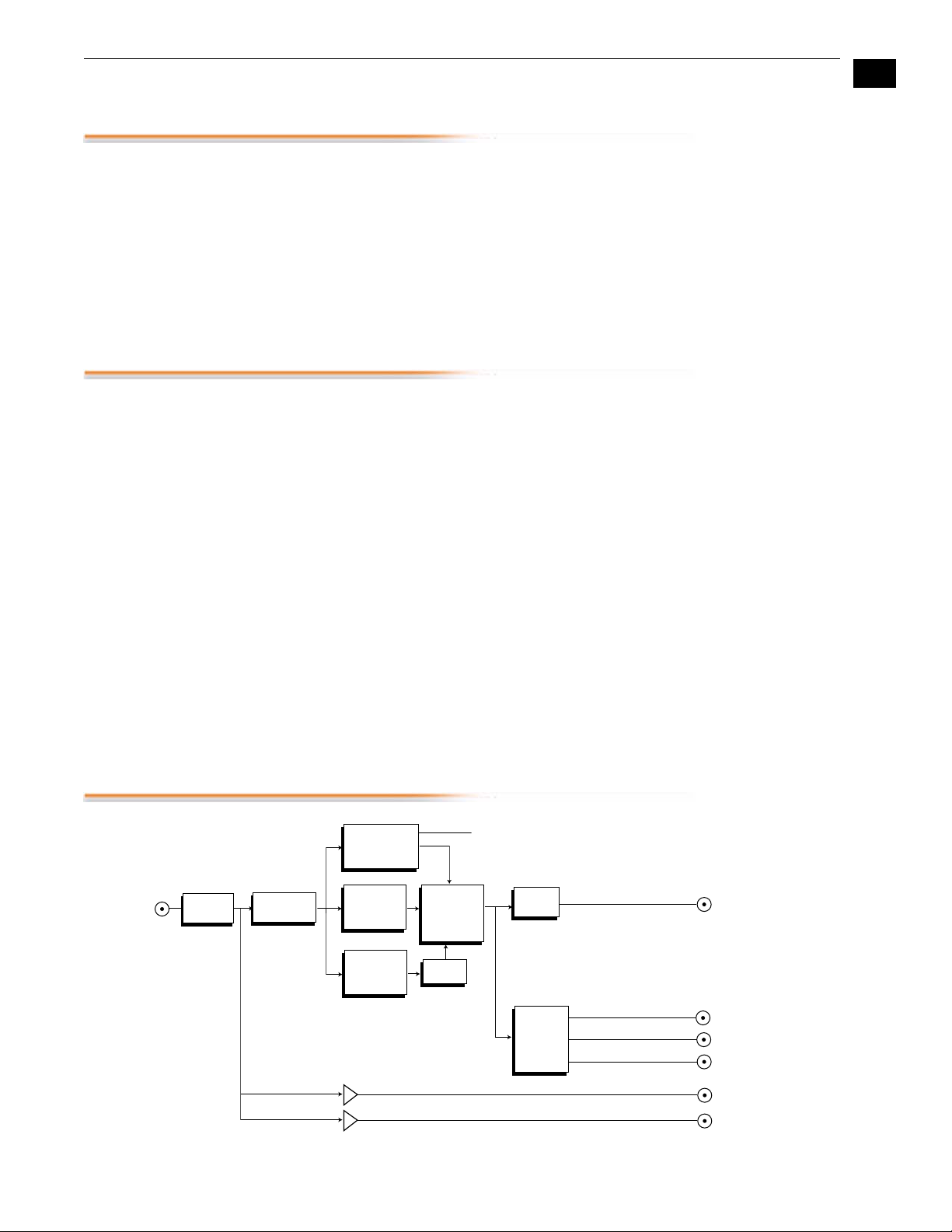
Block Diagram
Cable EQ
HD or SD
Input
DA Outputs
Note:
The HD10MD3 automatically switches to PAL anytime the input is 1080i 50,
1080psf 25 or 1080p25. All other frames rates have an NTSC output: 60, 59.94, 30,
29.97, 24 and 23.98.
3:2 Pulldown Synchronization
Audio
RP188
Timecode
Delay
Serializer
D/A
Conversion
Y G Composite
Pb B Y
Pr R C
SDI Output
Component/Composite Outputs
(selected by DIP switch)
HD-SDI Out 1
HD-SDI Out 2
De-serializer
RP188/RP215
Timecode
Extraction
H & V
Filtering and
Decimation
Embedded
Audio
Extraction
Embedding &
Embedding
HD10MD3 HD to SDI Down Converter, Block Diagram
Page 4

4
I/O Connections
HD/SD Input
BNC
HDSD Loop
Output 1
BNC
HD Loop
Output 2
BNC
+ 5 to 18VDC
Power
Input
User Controls
HD10MD3, Side View
The user interface for the HD10MD3 is an 8switch DIP accessible through a cut-out in the
bottom of the unit. Use the DIP switches to
configure outputs, pedestal, blanking, and
enable or disable noise reduction.
The exact function of each DIP switch and
what it controls is described on the following
pages.
SDI Output BNC
Composite/
Component
Output BNCs
Configuration
Determined by
DIP switch on
other side of
Converter
1
2
3
4
5
6
7
8
8
A jumper accessible by removing the DIPswitch side of the case (requires removal of 4
screws) allows you to select further options
described later.
DIP Switches
LEFT RIGHT
Switch 1—Selects Component or Composite Video on 3 Output
BNCs
:
LEFT RIGHT
Selects Component output Selects composite video output
Page 5

AJA HD10MD3 HD to SDI Down Converter User Manual — User Controls
Switch 2—Selects Type of Component Video on 3 Output BNCs
:
LEFT RIGHT
Selects YPbPr Selects RGB
Switch 3—Turns Pedestal OFF/ON. In YPbPr Mode, use BETA Levels
:
LEFT RIGHT
Pedestal Off Pedestal On. This setting also
changes analog output to BETA
levels when in YPbPr mode
1
Switch 4—Format Crop Letterbox OFF/ON
:
LEFT RIGHT
No crop Crop On—if S5 switch
set to 4:3 position
MONITOR
is
5
Switch 5—Selects Monitor Output to 4:3 or 16:9
:
LEFT RIGHT
Selects 4:3 Selects 16:9
Switch 6—Turns Focus ON/OFF
LEFT RIGHT
Turn Focus OFF Turn Focus ON; zoom to center 720
x 486 image
Switch 7—Turn 4:3 Graticule ON/OFF
:
LEFT RIGHT
Turn Graticule OFF Turn Graticule ON (4:3 safe area)
Note:
Switch 8 has no function.
Page 6

6
Jumper Settings
Jumper J8 is located next to the DIP Switch. To access it, remove the back of the
HD10MD3 case by first removing the 4 phillips screws that secure it. The meaning of the
jumper settings is described in the illustration below:
6
5
4
Jumper
J8
Jumper Between Pins 1 and 2:
1
ON = RP215 is used to synchronize 3:2 pulldown sequence
2
OFF = RP188 is used.
3
In both cases the “A Frame” is synchronized to frame with timecode “xx:00”
Jumper Between Pins 5 and 6:
ON = Output start of vertical blanking lines up with input start of vertical blanking
OFF = Output start of vertical sync lines up with input start of vertical sync (per RP168)
Page 7

1.
2.
3.
4.
Output Selection
Matrix For Output
3 BNCs
AJA HD10MD3 HD to SDI Down Converter User Manual — Installation
The following table shows the combinations of DIP switch settings required to configure the
three BNCs below the SDI Output BNC.
Output Format
1 Composite and 1 Y/C (Pedestal) RIGHT—
1 Composite and 1 Y/C (no pedestal) RIGHT—
RGB LEFT—
RGB with pedestal LEFT—
SMPTE component (BETA625)/
EBU-N10
BETA 525 component LEFT—
DIP Switch#1DIP Switch#2DIP Switch
#3
CMPSTE
CMPSTE
CMPNT
CMPNT
LEFT—
CMPNT
CMPNT
N/A RIGHT
N/A LEFT
RIGHT—RGB LEFT
RIGHT—RGB RIGHT
LEFT—
YPbPr/
LEFT—
YPbPr/
1
LEFT
RIGHT
7
Installation
Specifications
Typically, HD10MD3 installation consists of the following:
disconnect +5VDC from the convertor
configure the DIP switch for the desired equipment configuration and video formats
connect video equipment to the convertor BNCs
apply +5VDC power to the converter (AJA power supply model DWP)
Item Specification
Formats 1080i 50/59.94/60Hz
1080p/psf 23.98/24/25/29.97/30 Hz
720p 50/59.94/60Hz
(Automatic Configuration)
Inputs HD-SDI or SDI SMPTE 259/292/296, 10-bit, BNC
Outputs SDI, SMPTE 259M, 10-bit, BNC
YPbPr - SMPTE, EBU-N10, Betacam
RGB, NTSC, PAL, YC (S-Video), 10-bit
3 x BNC
Down Conversion Multi-point interpolation, 10-bit processing.
Frequency Response Y +0, -.5db to 30 MHz
3:2 conversion for 23.98/24p/psf inputs
C +/- .25db to 15 MHz
Page 8

8
Item Specification
User Controls
Size 5.8" x 3.1" x 1 (147 x 79 x 25mm)
Power 5-18V, 5 watts. Requires power supply.
ExternalDipswitch:
Output Video Format
4:3/16:9 MonitorSelect
Letterbox/Crop
Pedestal (Output)
4:3 Safe-Zone Graticule Overlay
 Loading...