

AJA FS-HDR User Manual

Overview
FS-HDR
Quick Start Guide
FS-HDR, a 1RU, rack-mount, universal converter/frame synchronizer, is designed
specifically to meet the HDR (High Dynamic Range) and WCG (Wide Color Gamut)
needs of broadcast, OTT, post and live event AV environments, where real time,
low-latency processing and color fidelity is required for 4K/UltraHD and 2K/HD
workflows. Developed in partnership with Colorfront, the FS-HDR’s HDR/WCG
functionality is powered by Colorfront Engine™ proprietary video processing
algorithms. FS-HDR also serves as a full, 1-channel up, down, cross-converter for
4K/UltraHD/2K/HD conversion and frame sync needs and in 4-Channel mode,
offers 4 independent channels of 2K/HD conversion.
Quick Start Guide Objectives
The FS-HDR can be extremely simple to use, because of its ability to detect
incoming signal formats and automatically apply the correct video processing for
the selected output format. However, the FS-HDR is also extremely powerful and
can be flexibly configured to perform a wide variety of tasks.
This Quick Start Guide is designed to help you get your FS-HDR up and running
for the first time, and confirm it is operating properly. It also provides step-bystep instructions that demonstrate a few FS-HDR signal processing examples.
Stand Alone Tests
• "First Power Up" on page 4
• "Internal Test Signals" on page 5
Computer Setup
• "FS-HDR Network Setup" on page 6
Processing Examples
• "HD Video Camera to UltraHD HDR Live Production" on page 9
• "4K HDR to HD HDR Down and Cross-Conversion" on page 11
• "Multiple Legacy Device SDR To HDR Live Conversion" on page 13
• "Multiple Simultaneous HDR and SDR Distribution" on page 15
For additional information, please see the FS-HDR Installation and Operation Guide
available on the AJA website.
Published September 6, 2017
FS-HDR Quick Start Guide v1.0 1 www.aja.com

HDR and WCG Background
High Dynamic Range (HDR) and Wide Color Gamut (WCG) are relatively new ways
to present video programming that gives brighter highlights, more detailed
shadows, and enhanced colors with smoother gradients. HDR and WCG are
display oriented features, dependent on the capabilities of the device presenting
the video material.
Standards have been developed to help manage HDR signal flows, including:
• HDR-10 (for HDMI) - Uses a Perceptual Quantizer (PQ) curve that accounts for
the human visual response to maximize coding eciency. This standard also
uses static metadata to communicate signal characteristics to the monitor so
it can optimize its display characteristics to match the signal.
• Hybrid Log Gamma (HLG) - Uses a combination log and gamma curve to
achieve coding eciency of HDR signals while also allowing the same signal
to be shown on both standard and HDR displays. No metadata is required.
Other standards exist, or are in development, including some that have dynamic
metadata, which can be used by displays to adjust for the best possible picture
from scene to scene.
FS-HDR Colorfront Engine Settings
FS-HDR settings involved in Colorfront Engine transforms for HDR include:
Input Video Dynamic Range & Gamut
• SDR BT.709 100 Nits (default)
• PQ BT.2020 1000 Nits
• PQ P3D65 1000 Nits
• Hybrid Log Gamma BT.2100
• Sony S-Gamut3/S-Log3
• Arri Log C Wide Gamut
• Panasonic V-Log
• Red Log3G10 Wide Gamut
• Canon Log 2
• Canon Log 3
Output Video Format Dynamic Range & Gamut
• SDR BT.709 100 Nits (default)
• PQ BT.2020 1000 Nits
• Hybrid Log Gamma BT.2100
• Sony S-Gamut3/S-Log3
Installation Summary
1. Unpack the shipping box, inspect and inventory the contents, and read the
late-breaking news sheet, if any.
2. Install any optional SFP I/O modules by sliding them into the SFP cages in
the back. Use only AJA approved modules.
NOTE: The "Stand Alone Tests" on page 4 can be performed with the FS-HDR sitting
on a bench to test system operation before physically installing the unit.
FS-HDR Quick Start Guide v1.0 2 www.aja.com
RJ45 Ethernet
100 to 240V
AES/EBU Digital
System Selection Buttons:
Select Knob:
Status
Audio In
Channels 1-16
DB-25F Connector
3. Mount the physical chassis: front rack, rear rack, or deskmount—1 RU x 17.5
inches (44.45 cm) x 16 inches (40.65 cm). Do not block air ow through the
side vents.
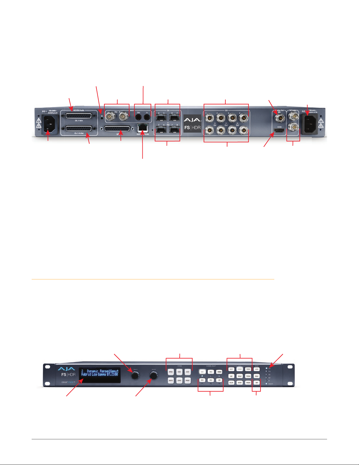
4. Make signal I/O connections to the FS-HDR back panel as shown in Figure 1.
Figure 1. FS-HDR Rear Panel
ID
LED
MADI BNC
Out/In
MADI Fiber
Out/In
SFP Input
SDI 6,5,8,7
SDI 1-4
Input BNCs
Monitor
Output BNC
AC Power
Socket #2
Autosensing
100 to 240VAC
50/60Hz
AC Power
Socket #1
Autosensing
50/60Hz
AES/EBU Digital
Audio Out
Channels 1-16
AC
DB-25F Connector
5. Connect one or two power cords to the FS-HDR and mains AC (100-240
VAC, 50/60 Hz, 55 Watts). For redundancy, use both cords and connect them
to separate branch circuits. The FS-HDR power supply is autosensing and
adjusts to the available power.
6. Connect your computer to the FS-HDR using a CAT5 Ethernet cable to the
FS-HDR RJ45 10/100/1000 Ethernet LAN connector. You can connect directly
or via a network device such as a switch, hub, bridge, etc. The FS-HDR
automatically senses and adjusts to either a straight-through or crossover
cable.
NOTE: See "FS-HDR Network Setup" on page 6 for more detailed instructions.
FS-HDR Control
The FS-HDR front panel buttons and knobs are used with menus in the display,
allowing you to fully configure the system. Front panel LEDs report important
system statuses. The FS-HDR also has an internal web server that allows remote
monitoring and control of parameter setting via an Ethernet 10/100/1000
network-attached computer running a web-browser. Firmware updates are also
performed from the web browser.
GPI 25-pin
DB-25F
Connector
10/100/1000
SFP Output
SDI 5, 6, 7, 8
SDI 1-4
Output BNCs
Monitor
Output HDMI
External Reference
I/O with looping
BNC connectors.
Figure 2. FS-HDR Front Panel
Scrolls and selects menus.
Push to undo changes.
Alphanumeric
Display
FS-HDR Quick Start Guide v1.0 3 www.aja.com
Adjust Knob:
Changes selected value.
Hold down for default value.
Press a button to select
a System Category
Channel Selection Buttons:
Press a button to select a
Video Processor or
Type of Audio
(Selection LED Lights)
Video Menu Group
Selection Buttons
Audio Menu Group
Selection Buttons
Indicator
LEDs

Stand Alone Tests
The stand alone tests can be performed without a computer, using the FS-HDR
front panel controls and rear connections. The following procedures assume
the FS-HDR is at factory defaults (taken from a newly opened box). If not set to
defaults, the FS-HDR may behave differently.
NOTE: FS-HDR units are configured at the factory to operate in Four Channel Mode.
First Power Up
The following workflow powers up a default FS-HDR and demonstrates some
example alarms.
Setup
• Ensure the FS-HDR is completely disconnected (all video, audio, network, and
power connector ports are empty).
Procedure
1. Connect both FS-HDR power cords to mains AC and allow time for the unit
to boot up. Observe the front panel LEDs.
• The REF LED will light red, indicating an alarm condition. By default the
FS-HDR is congured to operate genlocked to an external reference signal.
2. Press the front panel S TATUS button, then turn the SELECT knob to view
various Status menus.
• The Status menu for Video Processor 1 will report No Input for IN1, the
port is disconnected), and the GEN (Genlock) parameter will report Ref
(congured for external reference) but will also report No Input.
Video Format Status screen Video Format Alarm Status screen
IN1 SDI 1 No Input
BKGD Black 1080i59
GEN Ref No Input
OUT1 1080i59
3. Connect a 1080i59.94 HD tri-level sync reference signal to one of the FS-HDR
Ref Loop BNCs, and connect a 75 ohm terminator to the other Ref BNC.
• The REF LED will light blue, indicating the FS-HDR is genlocked to an
external reference signal.
• The Status menu GEN parameters will report Ref and indicate the format of
the incoming reference signal or OK.
• However, because the FS-HDR is still not receiving a compatible video input,
No Input, will be reported for IN1.
Video Format Status screen Video Format Alarm Status screen
IN1 SDI 1 No Input
BKGD Black 1080i59
GEN Ref 1080i59
OUT1 1080i59
4. Connect a 1080i59.94 SDI video source to the SDI 1 input BNC.
• The front panel will report 1080i59 and an OK status for SDI 1. This indicates
no alarm condition exists.
IN1 SDI 1 OK
BKGD Black OK
GEN Ref No Ref
Rate 59/29/23
IN1 SDI 1 OK
BKGD Black OK
GEN Ref OK
Rate 59/29/23
FS-HDR Quick Start Guide v1.0 4 www.aja.com

Video Format Status screen Video Format Alarm Status screen
IN1 SDI 1 1080i59
BKGD Black 1080i59
GEN Ref 1080i59
OUT1 1080i59
5. Disconnect one of the power cords, leaving the other attached.
• The front panel PWR LED will light red for the power supply with the
removed cord.
• The PS status will report PS1 (or 2) OFF
6. Reconnect the power cable. The PWR LED for that power supply will light
blue and the power supply status will report OK.
This workflow confirms the FS-HDR powers up successfully and reports reference
and power supply alarms.
NOTE: FS-HDR Reference, Power Supply, and Video Format alarms can be disabled, if
desired. This will prevent the LEDs from going red, but will not affect front panel
status displays.
Internal Test Signals
This workflow generates bars and tone and routes them to an FS-HDR video and
audio output. This example uses the SDI 1 and AES output connectors, an SDI
video monitor, and an AES audio monitor.
NOTE: In the following procedures, where the terms select and adjust are used, turn the
front panel SELECT and ADJUST knobs.
IN1 SDI 1 OK
BKGD Black OK
GEN Ref OK
OUT1 1080i59
Setup
• Connect the FS-HDR SDI 1 output BNC connector to an SDI video display with
a BNC cable.
• Connect the FS-HDR AES/EBU output DB25 connector to an AES audio
monitor using a standard TASCAM pinout cable (customer supplied). Separate
DB25 connectors carry all 8 AES digital audio pairs (16 audio signals), one
connector for input and one for output. Turn the output gain of the audio
monitor to a low level.
Procedure
1. Press the VID1 Channel Select button.
2. Press the FORMAT Video button
• Select 1 Output Format and adjust to a signal compatible with your SDI
monitor (for example, 1080i59.95).
3. Press the TSTGEN Video button.
• Select 1 Test Pattern Gen and adjust to On.
• Select 2 Test Pattern and adjust to 75% Bars.
4. Press the AES Channel Select button.
5. Press the MAP Audio button.
• Select 1.0 AES Out and adjust to Sig Gen 400KHz.
You should now be able to see the test signal on the SDI Monitor display, and hear
the audio on the AES monitor.
This workflow confirms the FS-HDR generates and outputs video and audio.
FS-HDR Quick Start Guide v1.0 5 www.aja.com

FS-HDR Network Setup
The following instructions summarize ways to configure the FS-HDR to
communicate with a computer directly or over a network.
Networking Using DHCP or Default Static IP
The FS-HDR factory default configuration automatically looks for a DHCP server
to issue an IP address. If your network includes a DHCP server, plug the FS-HDR
into the network and connect with the unit as follows:
1. Press the CONFIG button.
2. Turn the SELECT knob to navigate to the Status menu that has the name of
the FS-HDR at the top (default is “aja-FS-HDR”). Note the DHCP-supplied IP
address shown.
3. With your laptop or desktop computer connected to the same LAN as the
FS-HDR and DHCP enabled, type the IP address you noted on the FS-HDR’s
display into the browser address eld and press Enter. You should now see
the FS-HDR’s browser Status screen.
If the FS-HDR cannot get an address from the network DHCP server, the FS-HDR
will automatically use a preset factory static IP address of 192.168.0.2. You can
access the FS-HDR using the default static address as follows:
1. Set your computer’s IP address to whatever address you prefer in the
192.168.0 (classC) network.
2. Set the computer’s Subnet mask to 255.255.255.0 (most PCs default to the
proper netmask when the address is set).
3. Set the gateway address, if used, to match the FS-HDR default: 192.168.0.1.
Alternatively, change the FS-HDR gateway address to match your gateway:
A. Press CONFIG, turn SELECT to 3.4 Default Gateway, push and then turn
ADJUST to change the rst group of digits.
B. Turn SELECT to advance to the next set of numbers, and turn ADJUST to set
these numbers.
C. Continue using SELECT and ADJUST to set the full address.
D. When nished, push ADJUST momentarily to save the address.
5. Run a browser on the computer and type “192.168.0.2” (the factory static IP
address). You should now see the FS-HDR’s browser status screen.
Networking the FS-HDR Using Your Own Static IP
If you don’t want to use DHCP or the default static IP address, you can set your
own static IP address:
1. Select the CONFIG button and use the SELECT knob to navigate to
parameter 3.1 IP CONFIG. Use the ADJUST knob to select Static.
2. Turn SELECT to navigate to parameter 3.2 IP ADDRESS. The display shows
the default static IP address: 192.168.0.2.
3. Change the IP address as follows.
A. Push the ADJUST knob momentarily so that the rst octet (set of numbers)
blinks, and then turn ADJUST to change the numbers.
B. Turn SELECT to advance to the next set of numbers, and turn ADJUST to set
these numbers.
C. Continue using SELECT and ADJUST to set the full address.
D. When nished, push ADJUST momentarily to save the address.
FS-HDR Quick Start Guide v1.0 6 www.aja.com
 Loading...