


FS3
Frame Synchronizer/Converter
Installation and Operation Guide
Version 1.1r1
Published May 17, 2017

Notices
Trademarks
AJA® and Because it matters.® are registered trademarks of AJA Video Systems, Inc.
for use with most AJA products. AJA™ is a trademark of AJA Video Systems, Inc. for
use with recorder, router, software and camera products. Because it matters.™ is a
trademark of AJA Video Systems, Inc. for use with camera products.
CION®, Corvid Ultra®, lo®, Ki Pro®, KONA®, KUMO®, ROI® and T-Tap® are registered
trademarks of AJA Video Systems, Inc.
AJA Control Room™, KiStor™, Science of the Beautiful™, TruScale™, TruZoom™,
V2Analog™ and V2Digital™ are trademarks of AJA Video Systems, Inc.
AirPort, Apple, Apple logo, AppleShare, AppleTalk, FireWire, iPod, iPod touch,
Mac, Macintosh and ProRes, are registered trademarks of Apple Inc. Final Cut Pro,
QuickTime and QuickTime logo are trademarks of Apple Inc.
Avid, Avid DNxHD and Media Composer are registered trademarks of Avid
Technology, Inc.
Adobe is a registered trademark of Adobe Systems Incorporated in the United States
and/or other countries.
HDMI, the HDMI logo and High-Definition Multimedia Interface are trademarks or
registered trademarks of HDMI Licensing, LLC.
DVI is a registered trademark of DDWG.
TASCAM is a registered trademark of TEAC Corporation.
Dolby and the double-D Dolby logo are registered trademarks of Dolby Laboratories
Licensing Corporation.
openGear® Ross, ROSS, ROSS®, and MLE are registered trademarks of Ross Video.
DashBoard Control System™ is a trademark of Ross Video.
All other trademarks are the property of their respective holders.
Copyright
Copyright © 2017 AJA Video Systems, Inc. All rights reserved. All information in
this manual is subject to change without notice. No part of the document may be
reproduced or transmitted in any form, or by any means, electronic or mechanical,
including photocopying or recording, without the express written permission of AJA
Video Systems, Inc.
Contacting AJA Support
When calling for support, have all information at hand prior to calling. To contact AJA
for sales or support, use any of the following methods:
Telephone +1.530.271. 3190
FAX +1.530.271. 3140
Web https://www.aja.com
Support Email support@aja.com
Sales Email sales@aja.com
FS3 Frame Synchronizer/Converter v1.1r1 2 www.aja.com

Contents
Notices . . . . . . . . . . . . . . . . . . . . . . . . . . . . . . . . . . . . . .2
Trademarks . . . . . . . . . . . . . . . . . . . . . . . . . . . . . . . . . . . . . . . . . . . 2
Copyright . . . . . . . . . . . . . . . . . . . . . . . . . . . . . . . . . . . . . . . . . . . . 2
Contacting AJA Support . . . . . . . . . . . . . . . . . . . . . . . . . . . . . . . . . . . 2
Chapter 1 – Introduction . . . . . . . . . . . . . . . . . . . . . . . . . . . 7
Overview. . . . . . . . . . . . . . . . . . . . . . . . . . . . . . . . . . . . . . . . . . . . . 7
Video Features . . . . . . . . . . . . . . . . . . . . . . . . . . . . . . . . . . . . . . . 7
Audio Features . . . . . . . . . . . . . . . . . . . . . . . . . . . . . . . . . . . . . . . 8
Other Features. . . . . . . . . . . . . . . . . . . . . . . . . . . . . . . . . . . . . . . .8
FS3 Control . . . . . . . . . . . . . . . . . . . . . . . . . . . . . . . . . . . . . . . . . . . 8
Front Panel Control. . . . . . . . . . . . . . . . . . . . . . . . . . . . . . . . . . . . .8
Remote Web Browser Control . . . . . . . . . . . . . . . . . . . . . . . . . . . . . .8
GPI Inputs and Outputs . . . . . . . . . . . . . . . . . . . . . . . . . . . . . . . . . . 8
SNMP Interface Monitoring . . . . . . . . . . . . . . . . . . . . . . . . . . . . . . . 9
Optional FS3 Features. . . . . . . . . . . . . . . . . . . . . . . . . . . . . . . . . . . . .9
Fiber I/O . . . . . . . . . . . . . . . . . . . . . . . . . . . . . . . . . . . . . . . . . . . .9
Technical Description . . . . . . . . . . . . . . . . . . . . . . . . . . . . . . . . . . . . .9
Video Processor. . . . . . . . . . . . . . . . . . . . . . . . . . . . . . . . . . . . . . 10
Audio Processor. . . . . . . . . . . . . . . . . . . . . . . . . . . . . . . . . . . . . . 10
Operation Overview. . . . . . . . . . . . . . . . . . . . . . . . . . . . . . . . . . . . . 10
About Inputs and Outputs . . . . . . . . . . . . . . . . . . . . . . . . . . . . . . . 10
About Reference and Genlock Source. . . . . . . . . . . . . . . . . . . . . . . . 10
Sidebar Video Keying . . . . . . . . . . . . . . . . . . . . . . . . . . . . . . . . . . 11
Retained Settings. . . . . . . . . . . . . . . . . . . . . . . . . . . . . . . . . . . . . 11
In This Manual . . . . . . . . . . . . . . . . . . . . . . . . . . . . . . . . . . . . . . . . 11
Chapter 2 – Controls, Indicators, and Connections . . . . . . . . . . 12
Overview. . . . . . . . . . . . . . . . . . . . . . . . . . . . . . . . . . . . . . . . . . . . 12
Front Panel Description . . . . . . . . . . . . . . . . . . . . . . . . . . . . . . . . . . 12
Alphanumeric Display . . . . . . . . . . . . . . . . . . . . . . . . . . . . . . . . . . 12
Button Operation Rules . . . . . . . . . . . . . . . . . . . . . . . . . . . . . . . . . 13
Control Knobs . . . . . . . . . . . . . . . . . . . . . . . . . . . . . . . . . . . . . . . 15
LED Indicators . . . . . . . . . . . . . . . . . . . . . . . . . . . . . . . . . . . . . . . 16
Incompatibility Alarms . . . . . . . . . . . . . . . . . . . . . . . . . . . . . . . . . 17
Rear Panel Description . . . . . . . . . . . . . . . . . . . . . . . . . . . . . . . . . . . 18
Connectors. . . . . . . . . . . . . . . . . . . . . . . . . . . . . . . . . . . . . . . . . 18
Chapter 3 – Installation & Conguration . . . . . . . . . . . . . . . . 20
Installation Overview . . . . . . . . . . . . . . . . . . . . . . . . . . . . . . . . . . . . 20
Installation Summary . . . . . . . . . . . . . . . . . . . . . . . . . . . . . . . . . . . . 20
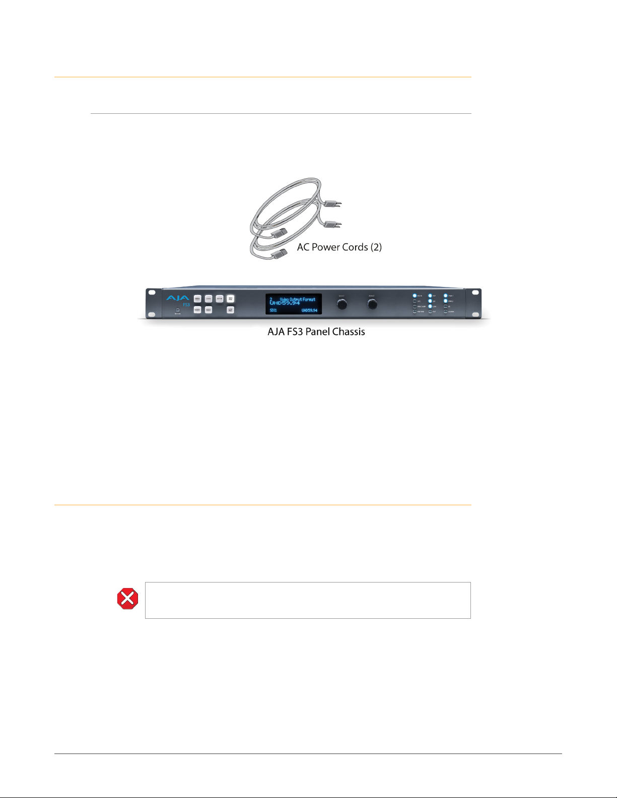
Unpacking . . . . . . . . . . . . . . . . . . . . . . . . . . . . . . . . . . . . . . . . . . . 21
Shipping Box Contents . . . . . . . . . . . . . . . . . . . . . . . . . . . . . . . . . 21
Installing Optional Fiber Optic I/O Modules. . . . . . . . . . . . . . . . . . . . . . 21
FS3 Chassis Installation . . . . . . . . . . . . . . . . . . . . . . . . . . . . . . . . . . . 22
Physical Requirements for Mounting the Chassis. . . . . . . . . . . . . . . . . 22
Power Requirements. . . . . . . . . . . . . . . . . . . . . . . . . . . . . . . . . . . 22
FS3 Network Setup . . . . . . . . . . . . . . . . . . . . . . . . . . . . . . . . . . . . . 22
FS3 Default Network Settings . . . . . . . . . . . . . . . . . . . . . . . . . . . . . 23
Networking Using DHCP or Default Static IP. . . . . . . . . . . . . . . . . . . . 23
Networking the FS3 Using Your Own Static IP. . . . . . . . . . . . . . . . . . . 24
Using Ping to Test the Network Connection . . . . . . . . . . . . . . . . . . . . 25
Web Browser Control . . . . . . . . . . . . . . . . . . . . . . . . . . . . . . . . . . . . 26
Software Update Installation . . . . . . . . . . . . . . . . . . . . . . . . . . . . . . . 26
Download the Latest Software . . . . . . . . . . . . . . . . . . . . . . . . . . . . 26
Unpack the Software . . . . . . . . . . . . . . . . . . . . . . . . . . . . . . . . . . 27
Uploading and Installing the Software to the FS3 . . . . . . . . . . . . . . . . 27
System Cabling. . . . . . . . . . . . . . . . . . . . . . . . . . . . . . . . . . . . . . . . 28
FS3 Frame Synchronizer/Converter v1.1r1 3 www.aja.com

System Video/Audio Cable Connections . . . . . . . . . . . . . . . . . . . . . . 28
GPI Connections . . . . . . . . . . . . . . . . . . . . . . . . . . . . . . . . . . . . . 28
Stand Alone Tests . . . . . . . . . . . . . . . . . . . . . . . . . . . . . . . . . . . . . . 28
First Power Up . . . . . . . . . . . . . . . . . . . . . . . . . . . . . . . . . . . . . . . 28
Internal Test Signals To All Outputs . . . . . . . . . . . . . . . . . . . . . . . . . 30
FS3 Processing Examples . . . . . . . . . . . . . . . . . . . . . . . . . . . . . . . . . 30
HD to UltraHD 4-Link Quadrant 59.94 . . . . . . . . . . . . . . . . . . . . . . . . 30
SD to 4K 4-Link 2SI 50 with Sidebar Matte . . . . . . . . . . . . . . . . . . . . . 31
Chapter 4 – Display Menus . . . . . . . . . . . . . . . . . . . . . . . . . 33
Overview. . . . . . . . . . . . . . . . . . . . . . . . . . . . . . . . . . . . . . . . . . . . 33
Parameter Menus. . . . . . . . . . . . . . . . . . . . . . . . . . . . . . . . . . . . . 33
Menu Operation Examples. . . . . . . . . . . . . . . . . . . . . . . . . . . . . . . 33
STATUS Menu Group . . . . . . . . . . . . . . . . . . . . . . . . . . . . . . . . . . . . 36
Vid Format Status . . . . . . . . . . . . . . . . . . . . . . . . . . . . . . . . . . . . . 36
Vid Format Alarm Status . . . . . . . . . . . . . . . . . . . . . . . . . . . . . . . . 36
Power/Temp Alarm Status . . . . . . . . . . . . . . . . . . . . . . . . . . . . . . . 37
Caption Status. . . . . . . . . . . . . . . . . . . . . . . . . . . . . . . . . . . . . . . 37
System Status . . . . . . . . . . . . . . . . . . . . . . . . . . . . . . . . . . . . . . . 37
REMOTE Menu Group . . . . . . . . . . . . . . . . . . . . . . . . . . . . . . . . . . . . 37
1 Remote Control . . . . . . . . . . . . . . . . . . . . . . . . . . . . . . . . . . . . . 38
1.1 Authentication . . . . . . . . . . . . . . . . . . . . . . . . . . . . . . . . . . . . 38
2.1–4 GPI IN 1–4 Response . . . . . . . . . . . . . . . . . . . . . . . . . . . . . . . 38
3.1–4 GPI 1–4 OUT . . . . . . . . . . . . . . . . . . . . . . . . . . . . . . . . . . . . 39
Interaction of Presets and GPIs . . . . . . . . . . . . . . . . . . . . . . . . . . . . 39
CONFIG Menu Group . . . . . . . . . . . . . . . . . . . . . . . . . . . . . . . . . . . . 40
1 System Name . . . . . . . . . . . . . . . . . . . . . . . . . . . . . . . . . . . . . . 40
2.1 IP Cong . . . . . . . . . . . . . . . . . . . . . . . . . . . . . . . . . . . . . . . . 40
2.2 IP Address . . . . . . . . . . . . . . . . . . . . . . . . . . . . . . . . . . . . . . . 40
2.3 Subnet Mask . . . . . . . . . . . . . . . . . . . . . . . . . . . . . . . . . . . . . 41
2.4 Default Gateway . . . . . . . . . . . . . . . . . . . . . . . . . . . . . . . . . . . 41
3 MAC Address (view only) . . . . . . . . . . . . . . . . . . . . . . . . . . . . . . . 41
4 SNMP Menu Parameters . . . . . . . . . . . . . . . . . . . . . . . . . . . . . . . 41
5 Power Supply Alarm . . . . . . . . . . . . . . . . . . . . . . . . . . . . . . . . . . 41
6 Video Format Alarm . . . . . . . . . . . . . . . . . . . . . . . . . . . . . . . . . . 42
7 Reference Alarm . . . . . . . . . . . . . . . . . . . . . . . . . . . . . . . . . . . . 42
8 Hidden Menus. . . . . . . . . . . . . . . . . . . . . . . . . . . . . . . . . . . . . . 42
9 Screen Saver . . . . . . . . . . . . . . . . . . . . . . . . . . . . . . . . . . . . . . . 42
10 Display Intensity. . . . . . . . . . . . . . . . . . . . . . . . . . . . . . . . . . . . 42
11 Fan Speed. . . . . . . . . . . . . . . . . . . . . . . . . . . . . . . . . . . . . . . . 43
12 Serial Number . . . . . . . . . . . . . . . . . . . . . . . . . . . . . . . . . . . . . 43
13 Software Version . . . . . . . . . . . . . . . . . . . . . . . . . . . . . . . . . . . 43
14 Reboot. . . . . . . . . . . . . . . . . . . . . . . . . . . . . . . . . . . . . . . . . . 43
PRESET Menu Group . . . . . . . . . . . . . . . . . . . . . . . . . . . . . . . . . . . . 43
1 Factory Preset . . . . . . . . . . . . . . . . . . . . . . . . . . . . . . . . . . . . . . 43
1.1-1.40 Presets #1-#40. . . . . . . . . . . . . . . . . . . . . . . . . . . . . . . . . . 44
Video with Audio Routing . . . . . . . . . . . . . . . . . . . . . . . . . . . . . . . 44
Interaction of Presets and GPIs . . . . . . . . . . . . . . . . . . . . . . . . . . . . 44
SYSTEM Menu Group . . . . . . . . . . . . . . . . . . . . . . . . . . . . . . . . . . . . 44
1 SDI1 3G Detect . . . . . . . . . . . . . . . . . . . . . . . . . . . . . . . . . . . . . 44
2 SDI2 Input Protect . . . . . . . . . . . . . . . . . . . . . . . . . . . . . . . . . . . 45
3 Fiber1 3G Detect . . . . . . . . . . . . . . . . . . . . . . . . . . . . . . . . . . . . 45
4 Fiber2 Input Protect . . . . . . . . . . . . . . . . . . . . . . . . . . . . . . . . . . 45
5 Genlock Source . . . . . . . . . . . . . . . . . . . . . . . . . . . . . . . . . . . . . 46
6 Output Frame Rates . . . . . . . . . . . . . . . . . . . . . . . . . . . . . . . . . . 46
VIDEO PROC Menu Group . . . . . . . . . . . . . . . . . . . . . . . . . . . . . . . . . 46
1 Input. . . . . . . . . . . . . . . . . . . . . . . . . . . . . . . . . . . . . . . . . . . . 46
2 Video Output Format . . . . . . . . . . . . . . . . . . . . . . . . . . . . . . . . . 47
3 Output Scan Format . . . . . . . . . . . . . . . . . . . . . . . . . . . . . . . . . . 47
4 Output Mode . . . . . . . . . . . . . . . . . . . . . . . . . . . . . . . . . . . . . . 47
5 Loss of Input . . . . . . . . . . . . . . . . . . . . . . . . . . . . . . . . . . . . . . . 48
FS3 Frame Synchronizer/Converter v1.1r1 4 www.aja.com

About Timing and Delay . . . . . . . . . . . . . . . . . . . . . . . . . . . . . . . . 48
6.1 Output Timing H . . . . . . . . . . . . . . . . . . . . . . . . . . . . . . . . . . . 49
6.2 Output Timing V . . . . . . . . . . . . . . . . . . . . . . . . . . . . . . . . . . . 49
6.3 Frame Delay . . . . . . . . . . . . . . . . . . . . . . . . . . . . . . . . . . . . . . 49
7 Background Fill . . . . . . . . . . . . . . . . . . . . . . . . . . . . . . . . . . . . . 49
8 Upconvert Mode . . . . . . . . . . . . . . . . . . . . . . . . . . . . . . . . . . . . 50
9 Sidebar Edge . . . . . . . . . . . . . . . . . . . . . . . . . . . . . . . . . . . . . . 50
About Frame Rate Output . . . . . . . . . . . . . . . . . . . . . . . . . . . . . . . 50
10.1 Cfg Hi Frm Rate Out . . . . . . . . . . . . . . . . . . . . . . . . . . . . . . . . 51
10.2 Cfg Lo Frm Rate Out . . . . . . . . . . . . . . . . . . . . . . . . . . . . . . . . 51
Matte of Background Fill Controls . . . . . . . . . . . . . . . . . . . . . . . . . . 51
Proc Amp Controls (YUV) . . . . . . . . . . . . . . . . . . . . . . . . . . . . . . . . 52
Color Corrector Controls (RGB) . . . . . . . . . . . . . . . . . . . . . . . . . . . . 53
Custom Conversion Settings. . . . . . . . . . . . . . . . . . . . . . . . . . . . . . 53
Region of Interest (ROI) Controls . . . . . . . . . . . . . . . . . . . . . . . . . . . 55
16.0 Video Legalizer . . . . . . . . . . . . . . . . . . . . . . . . . . . . . . . . . . . 56
AFD. . . . . . . . . . . . . . . . . . . . . . . . . . . . . . . . . . . . . . . . . . . . . . 57
18 Caption Xlator . . . . . . . . . . . . . . . . . . . . . . . . . . . . . . . . . . . . . 57
19 Input Scan Format . . . . . . . . . . . . . . . . . . . . . . . . . . . . . . . . . . 58
20 SD Line 21 Blanking . . . . . . . . . . . . . . . . . . . . . . . . . . . . . . . . . 58
21 Test Pattern . . . . . . . . . . . . . . . . . . . . . . . . . . . . . . . . . . . . . . 59
22 Freeze Output . . . . . . . . . . . . . . . . . . . . . . . . . . . . . . . . . . . . . 59
23 Reverse Telecine . . . . . . . . . . . . . . . . . . . . . . . . . . . . . . . . . . . 60
24 Downconvert Mode . . . . . . . . . . . . . . . . . . . . . . . . . . . . . . . . . 60
25 SD Aspect Ratio Convert . . . . . . . . . . . . . . . . . . . . . . . . . . . . . . 62
AUDIO PROC Menu Group . . . . . . . . . . . . . . . . . . . . . . . . . . . . . . . . . 63
1.0 SDI1 Level . . . . . . . . . . . . . . . . . . . . . . . . . . . . . . . . . . . . . . . 63
2.0 SDI1 Phase . . . . . . . . . . . . . . . . . . . . . . . . . . . . . . . . . . . . . . . 64
3.0 SDI1 Delay . . . . . . . . . . . . . . . . . . . . . . . . . . . . . . . . . . . . . . . 64
4.0/5.0/6.0 SDI 2 Level, Phase, Delay . . . . . . . . . . . . . . . . . . . . . . . . . 65
7.0/8.0/9.0 Fiber1 Level, Phase, Delay . . . . . . . . . . . . . . . . . . . . . . . . 65
10.0/11.0/12.0 Fiber2 Level, Phase, Delay . . . . . . . . . . . . . . . . . . . . . . 65
13.0 Mix Down Mode . . . . . . . . . . . . . . . . . . . . . . . . . . . . . . . . . . 65
15 Mix Down Reset . . . . . . . . . . . . . . . . . . . . . . . . . . . . . . . . . . . . 67
16 Embedded Audio Out . . . . . . . . . . . . . . . . . . . . . . . . . . . . . . . . 67
About Audio Routing . . . . . . . . . . . . . . . . . . . . . . . . . . . . . . . . . . 67
17.0 SDI1 Audio Output . . . . . . . . . . . . . . . . . . . . . . . . . . . . . . . . . 69
18.0-20.0 SDI2-4 Audio Out. . . . . . . . . . . . . . . . . . . . . . . . . . . . . . . 70
21 Global Audio Output. . . . . . . . . . . . . . . . . . . . . . . . . . . . . . . . . 70
22 Reset Mapped Output. . . . . . . . . . . . . . . . . . . . . . . . . . . . . . . . 70
Chapter 5 – Browser Remote Control . . . . . . . . . . . . . . . . . . 71
Remote FS3 Control Via a Web Browser . . . . . . . . . . . . . . . . . . . . . . . . 71
General Web Browser Screen Description . . . . . . . . . . . . . . . . . . . . . 71
Controlling Multiple FS3s. . . . . . . . . . . . . . . . . . . . . . . . . . . . . . . . 72
Resetting Values To Factory Default Settings . . . . . . . . . . . . . . . . . . . 73
Drop Down Parameter Operation . . . . . . . . . . . . . . . . . . . . . . . . . . 73
Slider Operation . . . . . . . . . . . . . . . . . . . . . . . . . . . . . . . . . . . . . 73
Sub-Menus . . . . . . . . . . . . . . . . . . . . . . . . . . . . . . . . . . . . . . . . . 73
Network Pane and Network Conguration Screen . . . . . . . . . . . . . . . . . 74
IP Address Type . . . . . . . . . . . . . . . . . . . . . . . . . . . . . . . . . . . . . . 74
IP Address . . . . . . . . . . . . . . . . . . . . . . . . . . . . . . . . . . . . . . . . . 75
Netmask. . . . . . . . . . . . . . . . . . . . . . . . . . . . . . . . . . . . . . . . . . . 75
Default Gateway . . . . . . . . . . . . . . . . . . . . . . . . . . . . . . . . . . . . . 75
Alarm Conguration Screen. . . . . . . . . . . . . . . . . . . . . . . . . . . . . . . . 76
Status Screen . . . . . . . . . . . . . . . . . . . . . . . . . . . . . . . . . . . . . . . . . 76
System Screen . . . . . . . . . . . . . . . . . . . . . . . . . . . . . . . . . . . . . . . . 77
Cong Screen . . . . . . . . . . . . . . . . . . . . . . . . . . . . . . . . . . . . . . . . . 78
System Name . . . . . . . . . . . . . . . . . . . . . . . . . . . . . . . . . . . . . . . 78
SNMP Parameters. . . . . . . . . . . . . . . . . . . . . . . . . . . . . . . . . . . . . 78
Hidden Menus. . . . . . . . . . . . . . . . . . . . . . . . . . . . . . . . . . . . . . . 79
FS3 Frame Synchronizer/Converter v1.1r1 5 www.aja.com

Display Intensity . . . . . . . . . . . . . . . . . . . . . . . . . . . . . . . . . . . . . 79
UPnP Host . . . . . . . . . . . . . . . . . . . . . . . . . . . . . . . . . . . . . . . . . 79
UPnP Proxy . . . . . . . . . . . . . . . . . . . . . . . . . . . . . . . . . . . . . . . . . 79
Presets Screen . . . . . . . . . . . . . . . . . . . . . . . . . . . . . . . . . . . . . . . . 80
Presets Screen Controls . . . . . . . . . . . . . . . . . . . . . . . . . . . . . . . . . 80
Interaction of Presets and GPIs . . . . . . . . . . . . . . . . . . . . . . . . . . . . 81
Video Screen . . . . . . . . . . . . . . . . . . . . . . . . . . . . . . . . . . . . . . . . . 82
Audio Screen . . . . . . . . . . . . . . . . . . . . . . . . . . . . . . . . . . . . . . . . . 83
Remote Screen. . . . . . . . . . . . . . . . . . . . . . . . . . . . . . . . . . . . . . . . 84
Firmware Screen . . . . . . . . . . . . . . . . . . . . . . . . . . . . . . . . . . . . . . . 84
Chapter 6 – SNMP. . . . . . . . . . . . . . . . . . . . . . . . . . . . . . .86
FS3 Simple Network Management Protocol . . . . . . . . . . . . . . . . . . . . . 86
SNMP Conguration . . . . . . . . . . . . . . . . . . . . . . . . . . . . . . . . . . . . 86
Front Panel Screens . . . . . . . . . . . . . . . . . . . . . . . . . . . . . . . . . . . 86
Web Browser. . . . . . . . . . . . . . . . . . . . . . . . . . . . . . . . . . . . . . . . 87
SNMP Conguration Parameters. . . . . . . . . . . . . . . . . . . . . . . . . . . . . 87
4.0 SNMP Enable . . . . . . . . . . . . . . . . . . . . . . . . . . . . . . . . . . . . . 87
4.1 SNMP Trap Destination 1 . . . . . . . . . . . . . . . . . . . . . . . . . . . . . . 87
4.2 SNMP Trap Port1. . . . . . . . . . . . . . . . . . . . . . . . . . . . . . . . . . . 88
4.3 SNMP Trap Destination 2. . . . . . . . . . . . . . . . . . . . . . . . . . . . . . 88
4.4 SNMP Trap Port2. . . . . . . . . . . . . . . . . . . . . . . . . . . . . . . . . . . 88
Appendix A – Specications . . . . . . . . . . . . . . . . . . . . . . . . 89
Appendix B – FS3 Pinouts. . . . . . . . . . . . . . . . . . . . . . . . . .93
GPI Pinouts . . . . . . . . . . . . . . . . . . . . . . . . . . . . . . . . . . . . . . . . . . 93
Appendix C – About SDI Video Formats. . . . . . . . . . . . . . . . .95
Origins, SD and HD, 1.5G . . . . . . . . . . . . . . . . . . . . . . . . . . . . . . . . . . 95
Evolution, 3G . . . . . . . . . . . . . . . . . . . . . . . . . . . . . . . . . . . . . . . . . 95
Further Evolution, 6G, 4K/UltraHD. . . . . . . . . . . . . . . . . . . . . . . . . . . . 95
FS3 SDI Formats . . . . . . . . . . . . . . . . . . . . . . . . . . . . . . . . . . . . . . . 96
Appendix D – Safety & Compliance . . . . . . . . . . . . . . . . . . . 97
Warranty Information . . . . . . . . . . . . . . . . . . . . . . . . . . . 106
Limited Warranty. . . . . . . . . . . . . . . . . . . . . . . . . . . . . . . . . . . . . . 106
Index. . . . . . . . . . . . . . . . . . . . . . . . . . . . . . . . . . . . . . 107
FS3 Frame Synchronizer/Converter v1.1r1 6 www.aja.com

Chapter 1 – Introduction
Overview
The new FS3 combines AJA’s industry-proven frame synchronization with
high-quality 4K up-conversion technology to seamlessly integrate SD and HD
signals into 4K workflows. AJA’s adaptive scaling algorithms, paired with our
well-known conversion technology ensures your up-converted images will have
the maximum quality possible. You can input SD or HD resolution SDI via BNC
or Fiber, and output up-converted 4K video to multiple BNC and Fiber outputs
simultaneously. FS3 also includes the industry-proven features included in AJA
frame synchronizers such as up, down, cross-conversion of SD, HD, and 3G-SDI
formats, RGB color correction, region of interest scaling, extensive audio controls
and routing, web UI control, GPI triggers and more, making it an extremely
versatile tool that can support a variety of production requirements.
Synchronizing diverse formats is a critical part of a broadcast, mobile or postproduction environment. FS3 syncs to analog SD blackburst, HD tri-level sync, or
to the incoming SDI signal. FS3 also provides integer frame rate conversion (3:2,
1:2, 2:1).
The growth of 5.1 and 7.1 audio has increased the number of audio channels that
must be managed in a production. FS3 accepts embedded SDI audio on all four
SDI inputs (two coax and two optional fiber), and has an internal 64x64 audio
matrix that allows routing of all embedded audio channels. Besides audio level,
phase, and delay controls, FS3 also provides for 5.1 or 7.1 mixdown to stereo.
Video Features
• Video format converter, that accepts SD, HD or 3G SDI video and up-converts
the signal to UltraHD (3840x2160) or 4K (4096x2160), and also up/down/cross
converts SD, HD, and 3G-SDI.
• The FS3 handles a wide variety of video output formats, including 4K/UltraHD
Quadrant (Square Division) and Two Sample Interleave (2SI). See "FS3 Tech
Specs" on page 89 for a complete list.
• Multiple mirrored outputs: three for Quad SDI, six for Dual SDI, and twelve for
Single SDI.
• Video proc amp and color correction.
• Frame synchronizer.
• User-specied custom format conversion and scaling with variable crop, size,
aspect, position, and Region of Interest parameters.
• Sidebar keying over black or matte.
• Closed captioning support.
• Active Format Description (AFD) support.
• Reverse Telecine.
FS3 Frame Synchronizer/Converter v1.1r1 7 www.aja.com

• Looping reference input with exible genlock.
Audio Features
• Embedded SDI audio (up to 64 in/out), with exible audio routing. Any or
all embedded audio inputs can be directed to any or all embedded audio
outputs. The same embedded audio is carried on the mirrored video outputs.
• Level and Phase, controls for every audio channel, and Delay controls for all
SDI audio channel pairs.
• 5.1 and 7.1 mix down to stereo.
• Supports pass-thru of synchronous non-PCM audio (Dolby E, Dolby D, etc).
Other Features
• Built-in front panel control via scrolling alphanumeric and graphical menu.
• Front panel LED status indicators for at-a-glance system monitoring.
• Linux operating system supporting full network compatibility, including Webbased remote control over 10/100/1000 Ethernet via an internal web server.
• Two fully redundant power supplies standard.
• Five-year international warranty with unlimited technical support.
FS3 Control
Front Panel Control
Remote Web Browser Control
FS3 operation can be monitored and changed in a number of ways. Feature sets
in each of the control methods vary, although the front panel and web browser
interfaces offer many of the same features.
The FS3 front panel offers the most direct control, ideal for use in machine rooms
or wherever quick changes and status checks must be made. The buttons and
knobs control menus in the display, allowing you to fully configure the system
according to your purposes. You can control inputs, outputs, processing paths,
keying, and much more.
The FS3 internally contains an optimized web server that allows remote
monitoring and parameter setting via an Ethernet 10/100/1000 network-attached
computer running a web-browser. Networks can be closed local area networks,
a direct computer-to-FS3 cross-over cable, or for greatest flexibility, exposed
through a firewall to a broadband WAN. From a network-connected computer
you can communicate with one or more FS3 devices, even getting them to
identify themselves via LEDs on the front and rear panel.
GPI Inputs and Outputs
General Purpose Inputs and Outputs are available on the FS3 back panel to
provide contact closure control. Using the inputs, an external contact closure
activates a specified function on the FS3. Using the outputs, specific FS3 functions
can produce a contact closure to activate any desired function on external
equipment. The functions to be activated by an input or that can activate an
output are set using the front panel and browser menus.
FS3 Frame Synchronizer/Converter v1.1r1 8 www.aja.com
SNMP Interface Monitoring
GPI Inputs
1
2
Remote Web
3
4
V
Embedded A
SNMP offers remote network monitoring of alarm conditions.
Optional FS3 Features
Fiber I/O
The FS3 supports optional AJA Optical Fiber I/O modules as follows:
• Single Input, LC connector
• Single Input SC connector
• Single Output LC connector
• Single Output SC connector
• Dual Input LC connectors
• Dual Output LC connectors
FS3’s Fiber I/O supports the 3G/HD/SD SDI protocol. Only AJA modules are
supported; use of other manufacturers’ modules is not supported and may void
the warranty.
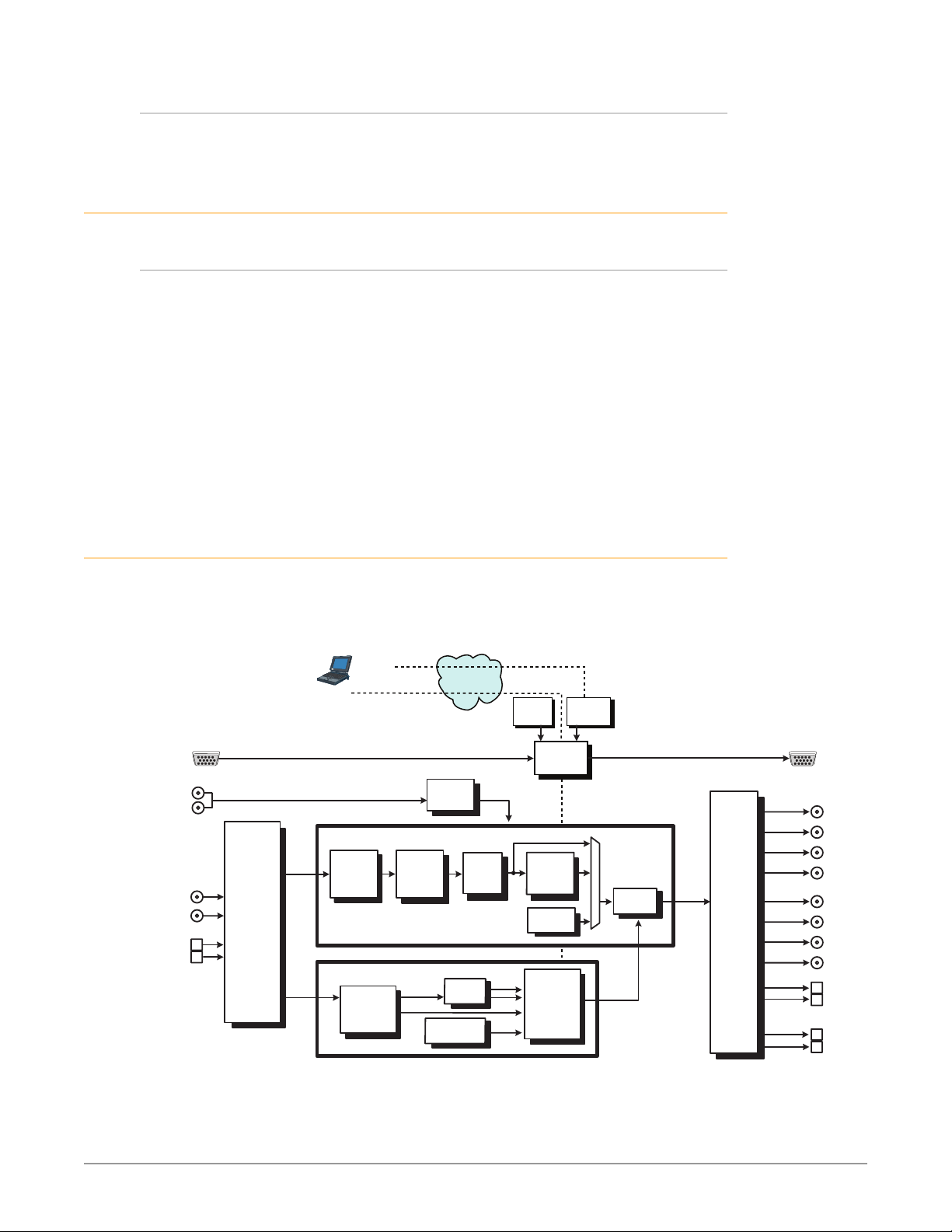
Technical Description
The FS3 features an incredibly flexible architecture, offering a powerful Video
Processor for video conversion and processing, a separate Audio Processor, and
input and output video and audio signal routing.
Figure 1. FS3 Simplified Block Diagram
SNMP Control
via command line
Inputs
(4)
Passive
Reference
Loops
ideo with
SDI In 1
SDI In 2
Optional
Fiber In 2
Optional
Fiber In 1
udio
Video
Input
Selector
Audio
Disembedders
Video
Audio
(64 Ch)
VIDEO PROCESSOR
Browser
Control
Video
Converter
and
Framesync
AUDIO PROCESSOR
Audio Level,
Phase, Delay
Adjustment
(64 Ch)
Video Proc
Amp and
Color
Corrector
L C R
(Ls Rs)
Lr Rr
LAN or WAN
Ethernet
Genlock
Mix
Down
Tone
Generator (2)
Video
Sidebar
Keyer
Panel
Control
Embedded
Web Server
OutputsProcessing
FS3 CPU
4K/UHD
Upconverter
Audio
Test Signal
Generator
L
R
Audio
Router &
Mapper
Embedder
Audio
(64 Ch)
Video
Video
Output
Drivers
GPI Outputs
(4)
SDI Out 1
SDI Out 2
SDI Out 3
SDI Out 4
SDI Out 5
SDI Out 6
SDI Out 7
SDI Out 8
Optional
Fiber Out
Optional
Fiber Out
Optional
Fiber Out
Optional
Fiber Out
FS3 Frame Synchronizer/Converter v1.1r1 9 www.aja.com

Video Processor
The Video Processor performs format conversion, frame synchronization, signal
processing, and keying operations. Conversion is done with very high quality
scalers. De-interlacing is performed with high quality motion-adaptive processing
including diagonal filters. The Processing Amplifier and Color Corrector supports
video signal adjustment with standard Proc Amp controls and RGB color
correction.
Audio Processor
The FS3 can accept and route any embedded audio input to the logical SDI1 thru
SDI4 outputs. Audio on SDI1 thru SDI4 outputs is duplicated on SDI5 thru SDI8
and Fiber1 thru Fiber4 outputs.
Channel mapping allows different individual audio input channels to be routed to
different individual logical outputs. Any embedded audio input can be routed to
any embedded audio logical output using channel mapping.
An internal mixer is available that permits mixing down five inputs (5.1) or seven
inputs (7.1) to a left/right stereo mix.
FS3 does not perform digital audio sample rate conversion. The Dolby 5.1 and
similar schemes of digital encoded audio are passed unaltered, provided the
input is genlocked to the FS3 output.
About Embedded Audio Routing
The FS3 can disembed a set of 16 channels (8 pairs) of embedded digital audio
from each SDI input. Each set of audio channels are embedded into each logical
SDI1-SDI4 portion (SDIn) of the SDI signal.
When not using the FS3 channel mapping feature, each set of 16 audio channels
are routed together, from one SDIn source to one SDIn destination. Exactly which
FS3 physical output connector carries which set of embedded audio can vary,
depending on the FS3 configuration.
Operation Overview
About Inputs and Outputs
In general, to use the FS3 for video up-conversion, first select an Output Video
Format (with the VIDEO PROC, Video Output Format Menu) that is compatible
with the current FS3 genlock source (see below), then select an Input port (with
the VIDEO PROC, Input menu). The FS3 will automatically determine the selected
input video format and convert it to the selected Output Video Format. The
converted video is routed to the FS3 output ports, duplicating the signal on all
complete sets of available connectors.
About Reference and Genlock Source
A genlock source being used by the FS3 for reference must be compatible with
the FS3 video output format. These signals are compatible when they are both in
the same frame rate family (59.94/29.97/23.98, or 50/25, or 60/24).
The FS3 can be configured to operate with one of a variety of references,
including genlock to the signal from the Reference input connector, genlock to
the current video input signal, or Free Run. Your choice of reference needs to
FS3 Frame Synchronizer/Converter v1.1r1 10 www.aja.com

meet your individual facility requirements, and must be accounted for when you
configure the FS3 video output format.
Sidebar Video Keying
The FS3 can be configured to perform sidebar keying (useful when converting
with different image aspect ratios). Sidebar keying black or matte is available.
Retained Settings
The FS3 stores the current value of each operational parameter in Flash memory
so that the system returns to the same state after a power cycle.
The FS3 also stores independent values for many settings, so that if the unit
is configured for one operation, changed to a different operation, and then
returned to that prior operation, the settings for that prior operation are restored.
For example, changing the Video Input selection automatically selects new values
for Proc Amp parameters and RGB Proc Amp parameters. This is referred to as
Source Memory. Each video source remembers its own Proc Amp settings.
Similarly, changing the Output Format selection automatically selects new values
for H & V timing parameters. This is referred to as Output Timing Memory. Each
Output Format mode remembers its own H & V timing settings.
As another example, Output Format Mapping stores the Output Format selected
for any of the frame rates. That Mapped Output Format is recalled if the frame
rate selection is changed.
Forty different presets are available that can be used to restore the FS3 to a
previous state. Many parameters can be individually reset to factory values using
individual menus, or the entire FS3 can be reset to defaults (with the PRESET,
Factory Preset menu).
In This Manual
Chapter 1: Introduction provides an overview and a list of box contents.
Chapter 2: Controls, Indicators, and Connections describes controls, indicators,
and connections.
Chapter 3: Installation and Configuration provides complete instructions for
installing and configuring the FS3.
Chapter 4: Display Menus explains how to use the controls and display menus.
Chapter 5: Browser Control explains how to use the FS3 remotely via a web
browser on a network-attached computer.
Chapter 6: SNMP discusses FS3 support of SNMP.
Appendix A: Specifications presents a list of technical specifications for the
product.
Appendix B: Pinouts explains the rear panel connector pinouts.
Appendix C: About SDI Formats provides a basic history of some of the SDI
standards.
Appendix D: Safety & Compliance provides regulatory compliance statements,
advisories and warnings.
Warranty and Index
FS3 Frame Synchronizer/Converter v1.1r1 11 www.aja.com
FMT ERR
ALARM
Line 4=Status/Legend
changes.
default value.
Menu Group Selection Buttons:
Chapter 2 – Controls, Indicators, and Connections
Overview
The controls, indicators, and connectors illustrated and described in this chapter
allow you to connect, operate, and monitor the FS3 system and to troubleshoot
problems if you encounter them. Becoming familiar with the front and rear panels
also simplifies system installation, setup, and operation.
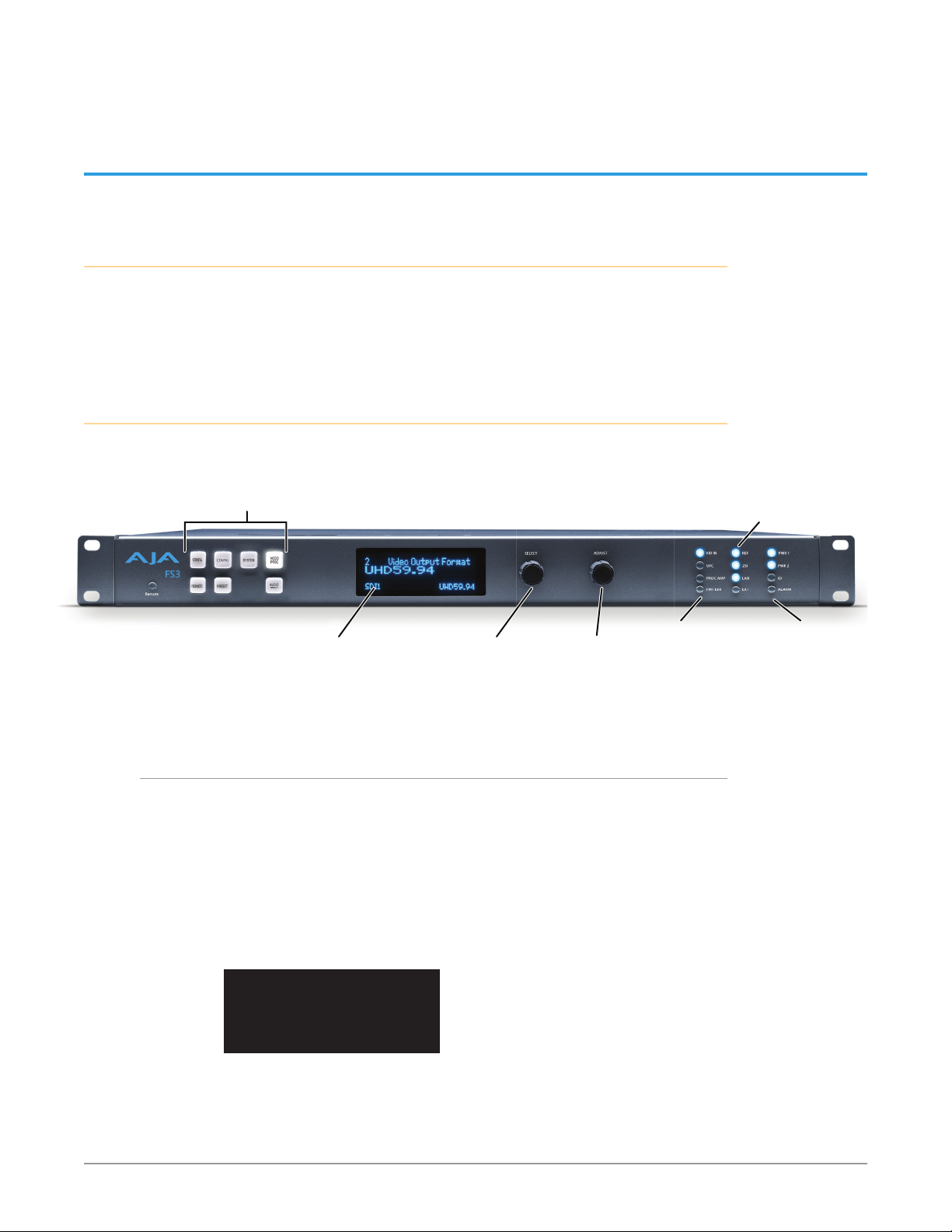
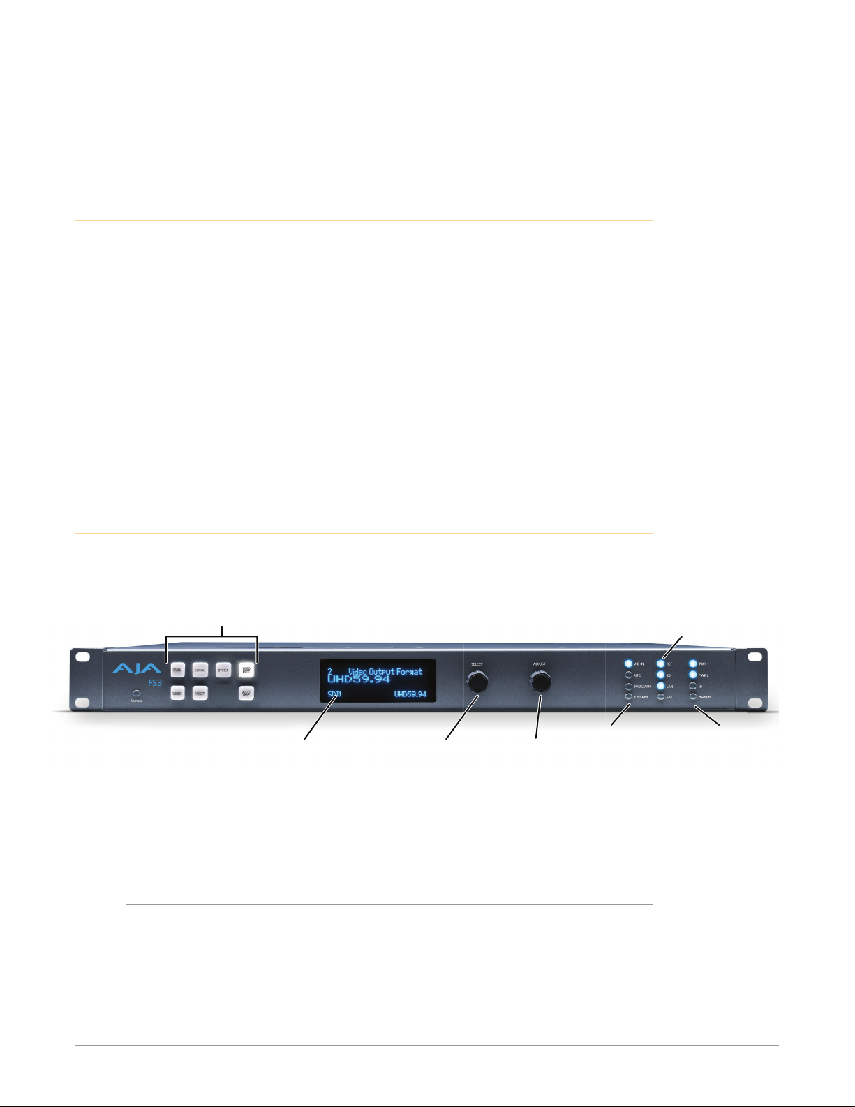
Front Panel Description
Figure 2. AJA FS3 Front Panel Controls and Indicators
Press a button to select
a Menu Group in the display
Alphanumeric Display:
Line 1=Parameter
Line 2=Parameter value
Line 3=Status/Legend
Alphanumeric Display
The FS3’s control system is designed to be quick and easy to use. The four-line
alphanumeric display shows menus that are numbered and grouped by function.
The menu groups are easily accessed using pushbuttons which correspond oneto-one with the groups (one button per menu group). The menu lines, which are
23 characters wide, display the following information:
• First line—parameter number and name.
• Second line—the editable value set for a parameter.
• Third and fourth lines—current status, labels, or prompts.
Select knob:
Scrolls and
selects menus;
Push to undo
Adjust knob:
Changes
selected value;
Hold down for
Activity
Indicators:
VID IN
UFC
Proc Amp
Status Indicators:
REF, 2SI, LAN, EXT
Power and
Status Indicators:
PWR 1
PWR 2
ID
Figure 3. Four Lines of the Front Panel Display
FS3 Frame Synchronizer/Converter v1.1r1 12 www.aja.com
1 Param number & name
2 Current value setting
3 Legend, info or prompt
4 Legend, info or prompt
When you edit a parameter containing multiple values, such as the IP address, the
value currently being edited blinks.

Operational Summary
The seven front panel pushbuttons allow you to select display menu groups.
The two knobs allow you to change menus and set parameters within the menu
groups. These functions can be summarized as follows:
• Select a menu group: Press one of the seven pushbuttons.
• Scroll through menus in a group: Turn SELECT.
• Edit a menu parameter: Stop SELECT on the menu.
• Change a parameter value: Once the parameter is selected with SELECT, turn
ADJUST to set the value. Changes are applied immediately.
• To edit a multiple part parameter, such as the IP address, push the ADJUST
knob momentarily (the value blinks). To save the whole parameter after
editing, push ADJUST momentarily again.
• Coarse adjust a value (for use with parameters that have more than 10
selections):
• 10x speed - Hold down the menu group button (the button turns blue) and
turn ADJUST. The values will change in 10x increments.
• 100x speed (available for extremely wide-range parameters, like Audio
Delay) - After enabling 10x speed above, momentarily release and press that
group button a second time (the button turns light blue). Turning ADJUST
will now change the value in 100x increments.
• Undo a change (restore previous setting): Push SELECT momentarily.
• Reset to factory default: Hold down ADJUST for 4 seconds.
Button Operation Rules
The general rules of Menu Group button operation are:
• Press one of the Menu Group buttons to access the associated menu group.
The SELECT and ADJUST knobs control the display menus.
• The selected Menu Group button lights and the other buttons go low tally
• Each menu group returns to the last menu changed when you select the
button. After a reboot, each group displays the last menu selected.
• Hold down a button (turns blue) to make coarse adjustments using the
ADJUST knob. Release the button to make ne adjustments (see above).
STATUS
Displays the Status Menu Group, which shows current machine status and error
conditions:
• Video Input and status
• Caption status
• Reference and Genlock status
• Output status
• Power and Temperature status
• System Name display
• Alarms
REMOTE
Displays the Remote Menu Group, which lets you select how to control the FS3:
• Control by local front panel only, remote sources only, or local and remote
• Authentication
• GPI input and output behavior
FS3 Frame Synchronizer/Converter v1.1r1 13 www.aja.com

CONFIG
Displays the Config Menu Group, which lets you configure the FS3 for your
environment:
• System Name setting
• IP settings, MAC address
• SNMP settings
• Alarm control
• Hidden Menus, Screen Saver, and Display intensity
• Fan speed
• System serial number and software version
• System reboot
PRESET
Displays the Preset Menu Group, which accesses the memory registers:
• Store, Recall, and edit the names of Presets
• Factory Preset (defaults)
SYSTEM
Displays the System Menu Group, which lets you change or enable video and
audio input and system functions:
• Video input format settings, including 3G setup
• Genlock reference source selection
• Output frame rate selection
VIDEO PROC
Displays the Video Proc Menu Group that access Video Processor video input,
format, conversion, and video processing selections and adjustments:
• Input source selections
• Output format and mode
• Loss of input selection
• H and V timing and delay settings
• Background ll selection
• Up-convert mode, aspect, edge
• High and low frame rate output settings
• Matte adjustments
• Proc amp and color corrector
• Custom Size and Position and ROI settings
• Legalizer settings
• Active Format Descriptor (AFD) settings
• Caption translation selection
• Input scan format settings (PsF or interlaced)
• SD line 21 blanking selection
• Test pattern and freeze output settings
AUDIO PROC
Displays the Audio Proc Menu Group, used to control the adjustable audio
parameters:
• Audio level, phase, and delay settings
• Embedded audio out settings
FS3 Frame Synchronizer/Converter v1.1r1 14 www.aja.com

• 5.1 and 7.1 Mix Down adjustments
• Audio source selections
• Global output selection
• Output mapping controls
Control Knobs
These are the general rules of SELECT and ADJUST knob operation:
SELECT
Turning the SELECT knob performs these actions:
• Turn SELECT in either direction to scroll through the menus.
• Stop on a menu to enter that menu for editing.
• Turn SELECT within a menu to scroll through multiple parameters.
• Pause on a parameter to select it for editing. For multiple elds in a parameter,
use SELECT to move through the elds (after pressing ADJUST to enter eld
editing mode).
• Push SELECT momentarily to undo and restore the previous setting.
ADJUST
Turning the ADJUST knob performs these actions:
• Turn ADJUST to change the values of a selected parameter.
• In most cases, leaving a value in place for a moment sets that value.
• To perform special actions, such as recalling a register, push the knob to
conrm the displayed value. Display line 4 indicates such special actions.
• Some parameters having multiple elds, such as IP Address require you to
push the DJUST knob to select a eld, and push again to save changes.
• Hold down the knob to reset a value to the factory default; for multiple eld
values, all elds are reset to the default.
• When the STATUS button is selected, pressing ADJUST returns the user to the
last mode and menu selected before SYSTEM -> STATUS was selected.
Table 1. SELECT and ADJUST Knob Operation Summary
Function Knob Action
Scroll through menus.
Scroll through parameters in a multiparameter menu.
Scroll through numerals or letters in a parameter.
Enter edit mode for a menu.
Enter edit mode for a parameter.
Enter edit mode for values, numerals, or letters.
Advance to the next value, numeral, or character to edit.
Increment/decrement a value. Turn ADJUST.
Coarse adjust a value. 10x speed - Hold down button (turns blue) and turn
Reset a value to the factory default value.
Set a number to the default value (typically zero).
Turn SELECT backwards or forward.
Turn and stop SELECT on the item to edit. (For some
multiple parameter menus, push ADJUST so that the
selected parameter blinks.)
ADJUST.
- or 100x speed - Hold down button (turns blue),
momentarily release and press button again (turns
light blue) and turn ADJUST.
Hold down ADJUST.
FS3 Frame Synchronizer/Converter v1.1r1 15 www.aja.com

Function Knob Action
Take (commit) a change to an edited parameter. Automatic for most parameters. For multiple eld
parameters, push ADJUST momentarily to save.
Abandon (undo) a change before committing. Push SELECT momentarily.
Take (commit) a special action, such as a preset recall. Push ADJUST momentarily.
LED Indicators
Indicators on the front panel are multi-state LEDs that light when a condition is
present. The indicators and the conditions that cause them to light are as follows:
REMOTE
A multicolor LED that indicates the current control mode:
• Green = Local Only (front panel control only)
• Red = Remote Only (remote browser or panel control only)
• Amber = Local + Remote (front panel and remote control both enabled)
VID IN (blue)
An active video input signal is detected.
UFC (blue)
The Universal Format Converter has been changed from the default setting.
PROC AMP (blue)
The Proc Amp has been changed from the default setting.
FMT ERR (blue)
The selected input and output formats are incompatible.
REF (blue)
The REF connector has an external reference video source applied.
2SI (blue)
The processor’s output scan format is set to Two Sample Interleave (2SI).
LAN (blue)
The FS3 is connected to an operational local area network. This indicator lights
momentarily when web browser selections are changed.
EXT (blue)
Flashes when a GPI has initiated a change in the system.
PWR 1/2 (blue)
Power Supply 1 or 2 is operational and receiving power. Both PWR 1 and PWR 2
LEDs must be lit to indicate redundant power is available.
ID (blue)
Blinks on and off when you right-click on an FS3 system name and choose
Identify in the web interface Network list. This action helps identify which system
FS3 Frame Synchronizer/Converter v1.1r1 16 www.aja.com
you’re controlling when multiple units are operated from a single computer. The
ID LEDs on the front and rear panels perform the exact same function. No matter
which side of a rack you’re facing, you’ll be able to see one of the LEDs.
ALARM (red)
An alarm event has been detected. Press the STATUS button for information.
The Alarm LED may light because of a disconnected or failed power supply,
other hardware failure, video incompatibilities, or loss of reference. (Any of these
conditions may be suppressed using the Alarm Suppress parameters.)
Incompatibility Alarms
The FS3 produces signal incompatibility alarms for a number of reasons. For
example, incompatible conversion alarms can occur because the FS3 cannot
convert between frame rate families (59.94/29.97/23.98, or 50/25, or 24).
Example Alarms
Video incompatibilities that the FS3 may detect include the following examples:
Table 2. Video Incompatibility Example
Video Incompatibility Detected Alarm Status screen will show Video Status screen will show
Genlock Source is set to “Reference”,
but no Reference signal is detected.
In this example the cable has been
disconnected.
Reference signal format is not
compatible with selected Output
Format. In this example the reference
signal is 50 Hz but output is 59.94 Hz.
IN SDI 1 OK
BKGD Matte OK
GEN Ref No Ref
OUT1 1080i59
IN SDI 1 OK
BKGD Matte OK
GEN Ref incompat
OUT 1080i59
IN SDI 1 1080i59
BKGD Matte
GEN Ref No Input
OUT1 UHDp59
IN SDI 1 1080i59
BKGD Matte
GEN Ref 1080i50
OUT1 UHDp59
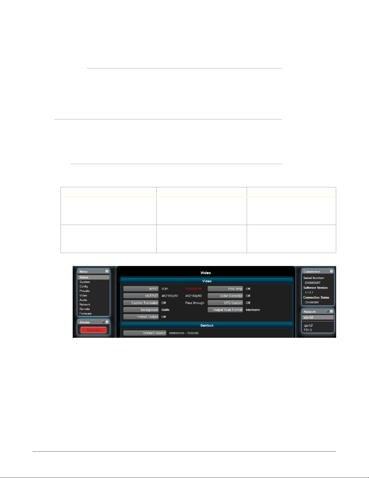
Figure 4. Web Page Example of Un-Supported Signals Alarm
FS3 Frame Synchronizer/Converter v1.1r1 17 www.aja.com
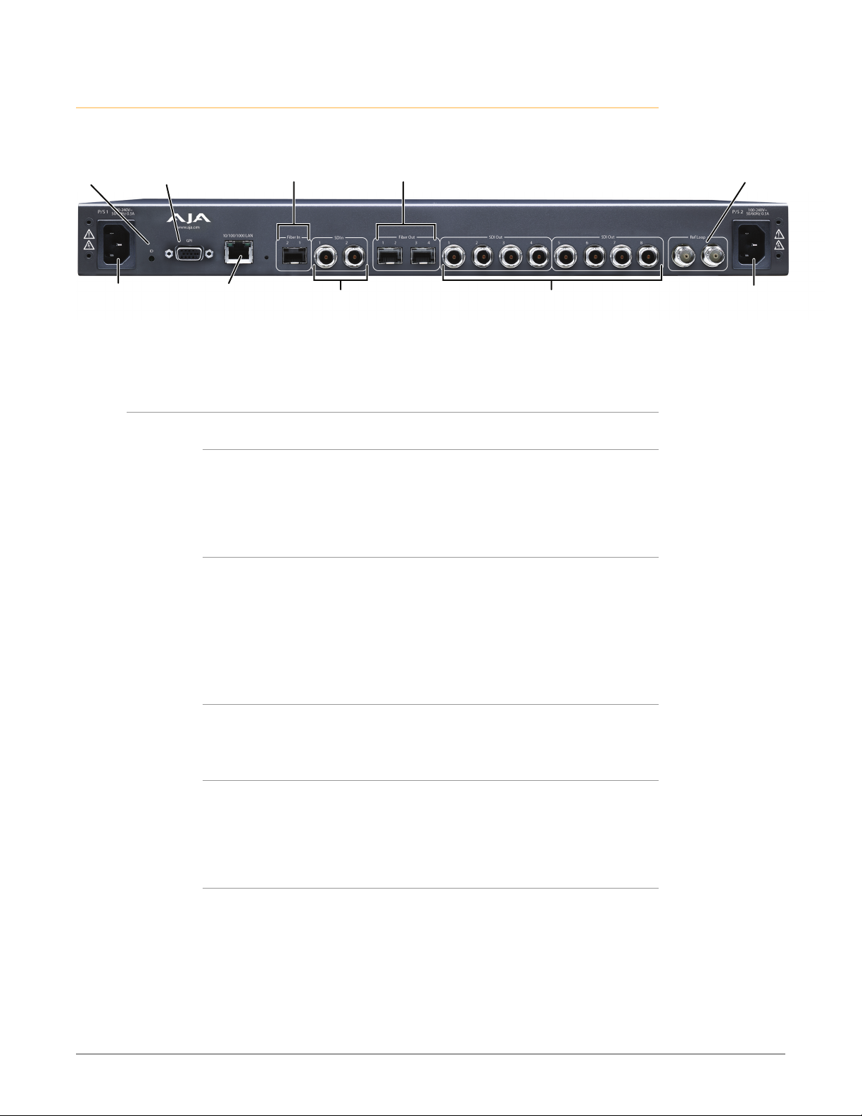
Rear Panel Description
External Reference
Serial Digital
Serial Digital
Figure 5. AJA FS3 Rear Panel
ID
LED
AC Power
Socket #1
Autosensing
100 to 240VAC
50/60Hz
GPI DA-15F
Connector
Connectors
Fiber Out (4)
(3G/HD/SD)
Serial Digital
Out BNC (8)
(3G/HD/SD)
10/100/1000
RJ45 Ethernet
LAN Connector
Fiber In (2)
(3G/HD/SD)
Serial Digital
In BNC (2)
(3G/HD/SD)
PS 1 and PS 2
Two 3-pin sockets provide AC power to the two independent power supplies.
The supplies are autosensing for 100–240 VAC, 50/60 Hz. Only one connection is
required for operation, but both connectors must be plugged into AC power for
redundant power protection.
GPI
I/O with looping
BNC connectors.
AC Power
Socket #2
Autosensing
100 to 240VAC
50/60Hz
The GPI DB-15F connector provides connection to external equipment or circuits
via an isolated TTL-compatible interface. Four GPI inputs and four outputs are
available. See "GPI Pinouts" on page 93.
Using the REMOTE menu group, you can program the actions of the GPI inputs
and outputs individually. Contact closures on the inputs can trigger a wide variety
of FS3 functions. Alarms or loss of video can trigger the GPI outputs.
10/100/1000 L AN
This RJ-45 connector provides an Ethernet 10/100/1000 port for connection
directly to a computer or to a LAN through an Ethernet hub or switch.
SDI (BNC) In/Out
Digital video with embedded audio. Two SDI input and eight SDI Output BNCs.
10 bit 3G SDI is supported. Up-converted signals are replicated on each set of
additional BNC outputs (two quad BNC signal sets, four dual BNC sets, or 8 single
BNCs).
SDI (Fiber) In/Out (optional)
Two optional Single-Mode Optical Fiber SFP input modules support single- or
dual-channel Fiber Input and/or Output. 3G SDI protocol is supported. Only AJA
Optical Fiber SFP modules are supported—use of other manufacturer’s modules
is not supported and may void warranty. Up-converted signals are replicated on
each set of additional Fiber outputs (one quad fiber set, two dual fiber sets, or
four single fibers).
FS3 Frame Synchronizer/Converter v1.1r1 18 www.aja.com

Ref Loop
The Reference Loop BNCs accept an Output timing reference signal. The
reference can be analog SD blackburst or HD tri-level sync. Examples of
permissible reference video input signals:
• 525 Color Black
• 625 Color Black
• 1080i Tri-level Sync
• 720p Tri-level Sync
The 2 BNCs are a passive loop: one BNC is for the Input, and the remaining BNC
can be connected to another piece of equipment in the reference chain or
terminated.
NOTE: For proper operation the input Reference signal must be stable and properly
terminated using a 75-ohm terminator on either the unused loop connector or
the last piece of downstream equipment to which the Ref Video is connected.
FS3 Frame Synchronizer/Converter v1.1r1 19 www.aja.com

Chapter 3 – Installation & Configuration
Installation Overview
The installation and set up of an FS3 is very simple. Plug both AC supply cords
into AC mains power (separate branch circuits for redundancy), connect the
LAN connector to a LAN, WAN or local computer with a web-browser, and then
connect source and destination video and audio equipment.
NOTE: The AJA FS3 should be plugged into grounded 3-wire 100-240 VAC 50/60 Hz
power outlets before you make connections to other equipment. The FS3 is
equipped with autosensing power supplies. The AC cords provide a path to
ground for accidental static discharge to protect system equipment. The unit has
two fully independent and redundant power supplies and will operate with one
or both AC power cords plugged into the unit. However, fault-tolerance exists only
if both power supplies are connected and plugged into separate branch circuits.
Then if power is lost on a branch or one of the supplies, the unit will continue to
operate on the remaining circuit and power supply.
Caution - To meet safety regulations for leakage current and to ensure redundancy
in the event that a branch circuit breaker shuts o a branch, connect the dual
power supplies to separate branch circuits.
Installation Summary
1. Unpack the shipping box, removing the FS3 and two power cords.
2. Install any physical options, such as ber optic I/O modules.
3. Mount the physical chassis as desired: front rack, rear rack, or desk mount. If
you are mounting multiple FS3 units, try to place them visually in the same
area so you can use an attached computer to turn on and see the ID LED of
the FS3 you’re communicating with.
4. Connect the two FS3 power cords to mains AC. For redundancy, use both
power supplies and connect them to separate branch circuits so that the
FS3 will continue to operate even if a circuit breaker opens on one branch.
5. If you plan to use remote control, connect your computer to the FS3 directly
using an Ethernet cable, or connect both the computer and the FS3 to a
local area network through an appropriate hub or router. Also set the FS3 IP
address in the menus, and then use a computer to test (ping) the FS3 over
the network connection to verify communication.
6. Install a web browser on your computer, if not already present, for accessing
the FS3 web pages. You can access the pages simply by entering the FS3 IP
address in the browser address eld.
7. Connect the FS3 to system audio and video sources, including VTRs,
monitors, DVD players, video switchers, etc.
8. Test the FS3 with all of your devices to verify everything is working.
FS3 Frame Synchronizer/Converter v1.1r1 20 www.aja.com
Unpacking
Shipping Box Contents
An FS3 chassis is shipped with two AC power cords and any late-breaking news
bulletins (if applicable). Chassis rackmount brackets are provided as part of the
chassis with screws.
Figure 6. Shipping Box Contents
As you unpack the shipping box, carefully examine the contents. Ensure you
received everything and that nothing was damaged during shipment. If you find
any damage, immediately notify the shipping service and supply them with a
complete description of the damage. AJA will repair or replace damaged items.
If you find shipping damage, contact your AJA dealer or distributor for details on
how to have your FS3 repaired or replaced.
NOTE: Save packing materials and the shipping box. If your FS3 ever requires service or
you move your system, use the packaging materials and box for safe shipment.
Installing Optional Fiber Optic I/O Modules
The optional AJA Fiber Optic I/O modules are purchased separately from the FS3.
These AJA fiber modules work with the FS3:
• Single-channel LC connector modules
• Single-channel SC connector modules
• Dual-channel LC connector modules
Caution! Only AJA ber optic I/O option modules may be inserted into the FS3
Fiber slots. DO NOT USE ber modules from other manufacturers; they will
damage the FS3 connectors and circuits.
Install the optional fiber I/O modules by inserting them into the rectangular holes
marked Fiber on the back panel with the electrical connectors facing downward.
Press gently but firmly until the modules seat in the inside connectors. For
additional installation and operation details, see the instructions provided with
the fiber modules.
FS3 Frame Synchronizer/Converter v1.1r1 21 www.aja.com

FS3 Chassis Installation
The following information will help you install the FS3 chassis correctly.
Physical Requirements for Mounting the Chassis
You can mount the FS3 chassis in two ways:
• Rackmounting—attach the FS3 (rear or front mounted) to a standard 19-inch
wide equipment rack. The chassis occupies only one vertical rack unit.
• Desktop—lay it on a horizontal at surface.
Chassis Dimensions
When planning the equipment location, consider the chassis dimensions:
• Height—1 rack unit, 1.75 inches (4.5 cm)
• Depth—16 inches (40.65 cm)
• Width—17.5 inches (44.45cm)
• Weight—7.85 pounds, 3.56 kilograms
Cabling and Cooling Requirements
Observe these precautions when placing your FS3:
• Plan adequate space for cable routing from the back of the chassis. Ensure that
cable connectors are not stressed and cables are not bent or crimped.
• When rack mounting or stacking multiple FS3 chassis, ensure adequate
airspace for cooling around the FS3 units. Note the location of cooling vents
on all equipment next to the FS3 and ensure none are obstructed.
NOTE: FS3 units can be stacked vertically without limit as long as there is an adequate
supply of cool air around the FS3 vents.
Power Requirements
NOTE: FS3 units can be stacked vertically without limit as long as there is an adequate
supply of cool air around the FS3 vents.
FS3 requires the following input voltage and power.
• Input Voltage—Chassis: autosensing 100VAC to 240VAC, 50/60Hz,
fully redundant with both power supplies diode isolated.
• Power Consumption—55W typical; 80W max
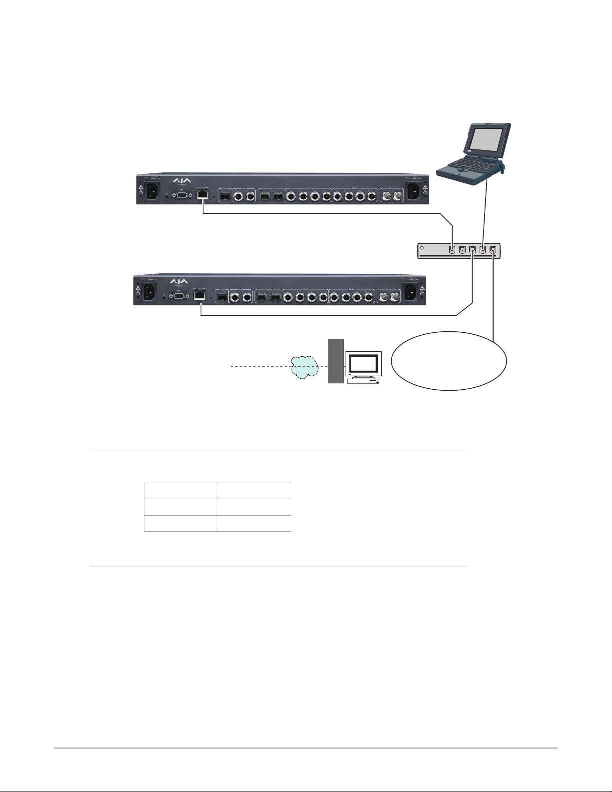
FS3 Network Setup
You can network the FS3 directly to a laptop or other desktop computer using a
single Ethernet cable (straight or cross-over), or connect it to a local area network
(LAN). In either case, the FS3 connects via its 10/100/1000 Base-TX Ethernet
connector. A LAN is a shared network that includes other Ethernet devices all
attached via a hub or digital switch. LANs may be divided into zones separated by
software or hardware routers. Routers may also be used to connect the LAN to an
outside wide area network (WAN) such as the internet.
Devices on a LAN have IP addresses which may be fixed and permanent or
dynamically assigned by the network (DHCP). When attaching the FS3 to a LAN,
talk to your network administrator to find out how they want it connected (static
FS3 Frame Synchronizer/Converter v1.1r1 22 www.aja.com
IP or DHCP). Your IT department will be able to supply the information you need
to install the FS3 on a LAN.
The following illustration shows a network connection example; your installation
may differ.
Figure 7. Network Example, Two FS3s on a LAN, with Laptop
Laptop
w/Web Browser
for Remote Control
10/100/1000 Base-T
Hub or Switch
10/100/1000 Base-T
WAN/ISP
Firewall
& Router
FS3 Default Network Settings
The FS3 ships from the factory set for DHCP networking, and can be manually
reset to the following default network settings:
IP Address 192.168.0.2
Subnet Mask 255.255.255.0
Gateway 192.168.0.1
Networking Using DHCP or Default Static IP
The FS3 factory default configuration automatically looks for a DHCP server to
issue an IP address. If your network includes a DHCP server, plug the FS3 into the
network and connect with the unit as follows:
1. Press the CONFIG button.
2. Turn the SELECT knob to navigate to cong parameter 2.2. Note on a piece
of paper the DHCP supplied IP address shown.
3. With your laptop or desktop computer connected to the same LAN as the
FS3 and DHCP enabled, type the IP address you noted into the browser
address eld and press Enter. You should now see the FS3’s browser Status
screen.
10/100/1000 Base-T
LAN
FS3 Frame Synchronizer/Converter v1.1r1 23 www.aja.com

If the FS3 cannot get an address from the network DHCP server, the FS3 will
automatically use a preset factory static IP address of 192.168.0.2. You can access
the FS3 using the default static address as follows:
1. Set your computer’s IP address to whatever address you prefer in the
192.168.0 (class C) network.
2. Set the computer’s Subnet mask to 255.255.255.0 (most PCs default to the
proper netmask when the address is set).
3. Set the gateway address, if used, to match the FS3 default: 192.168.0.1.
Alternatively, change the FS3 gateway address to match your gateway:
A. Press CONFIG, turn SELECT to 2.4 Default Gateway, push and then turn
ADJUST to change the rst group of digits.
B. Turn SELECT to advance to the next set of numbers, and turn ADJUST to set
these numbers.
C. Continue using SELECT and ADJUST to set the full address.
D. When nished, push ADJUST momentarily to save the address.
5. Run a browser on the computer and type “192.168.0.2” (the factory static IP
address). You should now see the FS3’s browser status screen.
When you can access the FS3 screens, see "Chapter 5 Browser Remote Control" on
page 71 for details about configuring the FS3 using a browser.
Networking the FS3 Using Your Own Static IP
If you don’t want to use DHCP or the default static IP address, you can set your
own static IP address:
1. Select the CONFIG button and use the SELECT knob to navigate to
parameter 2.1 IP CONFIG. Use the DJUST knob to select Static.
2. Turn SELECT to navigate to parameter 2.2 IP ADDRESS. The display shows
the default static IP address: 192.168.0.2.
3. Change the IP address as follows.
A. Push the DJUST knob momentarily so that the rst octet (set of numbers)
blinks, and then turn ADJUST to change the numbers.
B. Turn SELECT to advance to the next set of numbers, and turn ADJUST to set
these numbers.
C. Continue using SELECT and ADJUST to set the full address.
D. When nished, push ADJUST momentarily to save the address.
5. Turn SELECT to advance to 2.3 Subnet Mask. Use the SELECT and DJUST
knobs as in the previous step to set the desired subnet mask.
6. Turn SELECT to advance to 2.4 Default Gateway. Use the SELECT and DJUST
knobs as in the previous step to set the desired gateway address.
7. Run a browser on the computer and type in the IP address you set for the
FS3. You should now see the FS3’s Status screen.
See "Chapter 5 Browser Remote Control" on page 71 for details about configuring
the FS3 using a browser.
FS3 Frame Synchronizer/Converter v1.1r1 24 www.aja.com
Figure 8. Setting FS3 Static IP Address
Select the CONFIG
Menu Group button
Cong
Parameter Menu
1
2
3
Current Setting
Change setting to
STATIC Address
by turning the
ADJUST knob.
Cong
Parameter Menu
Current Setting
Push ADJUST to
edit octets.
Turn ADJUST
to change values.
Push ADJUST to save.
Cong
Parameter Menu
Current Setting
Push ADJUST to
edit octets.
Turn ADJUST
to change values.
Push ADJUST to save.
Turn the SELECT knob to scroll
to parameter menu 2.1 IP Cong.
2.1 IP Config
STATIC Address
Turn the SELECT knob to scroll
to parameter menu 2.2 IP Address.
Turn SELECT again as needed to
advance through the blinking octets.
2.2 IP Address
192.168.0.2
Turn SELECT to scroll to parameter
menu 2.3 Subnet Mask.
Turn SELECT again as needed to
advance through the blinking octets.
2.3 Subnet Mask
255.255.255.0
SELECT ADJUST
SELECT ADJUST
SELECT ADJUST
Turn SELECT to scroll to parameter
menu 2.4 Default Gateway.
Turn SELECT again as needed to
Cong
4
Parameter Menu
Current Setting
Push ADJUST to
edit octets.
Turn ADJUST
to change values.
Push ADJUST to save.
advance through the blinking octets.
2.4 Default Gateway
192.168.0.1
Using Ping to Test the Network Connection
If you have connected the FS3 to a computer and set up the IP address and still do
not see the FS3 screens in your browser, you can ping the network to verify the
connection. Simply run the Ping utility from a Mac OS X or Windows PC computer
attached directly or on the same LAN as the FS3 as described below:
Mac Ping Procedure
1. Find the Utilities Folder inside of the Applications Folder.
2. Locate the “Terminal” utility application and double-click it.
3. On the FS3, select the STATUS button and go to System Status menu (with
the FS3 name) to read the unit’s currently congured IP address.
SELECT ADJUST
FS3 Frame Synchronizer/Converter v1.1r1 25 www.aja.com

NOTE: The IP address reported on the CONFIG menu is a database entry, which
occasionally may not be the address the unit is using. The STATUS menu always
shows the correct value.
4. At the Mac terminal prompt, enter ping and the IP address noted above. For
example: ping 192.168.0.2
5. If successful, the ping utility will respond that packets were sent, received
and how long it took. For example:
64 bytes from 192.168.0.2: icmp_seq=0 ttl=64 time=0.590 ms
6. If unsuccessful, check the FS3 network settings and resolve the problem
with your IT administrator.
Windows PC Ping Procedure
1. From the Start button, select the All Programs menu.
2. Select Accessories/Command Prompt from the All Programs list.
3. On the FS3, select the STATUS button and go to System Status menu (with
the FS3 name) to read the unit’s currently congured IP address.
4. In the PC Command Prompt utility, enter ping and the IP address noted in
step 3. For example: ping 192.168.0.2
5. If successful, the ping utility will respond that packets were sent, received
and how long it took. For example:
64 bytes from 192.168.0.2: icmp_seq=0 ttl=64 time=0.590 ms
6. If unsuccessful, check the FS3 network settings and resolve the problem
with your IT administrator.
Web Browser Control
To control the FS3 from a web browser on a network attached computer, enter
the FS3 IP address as a URL in the browser. For example, if the FS3 IP address were
“90.0.6.31”, you would then type into the web browser: http://90.0.6.31. This topic
is explained in greater detail in Chapter 5: Browser Remote Control.
NOTE: The web UI (browser GUI) will keep up with most changes initiated at the front
panel. However, the web UI may not reconnect (displays “Disconnected”) when
network changes are initiated at the FS3 front panel. To manually reconnect,
type the new IP address into the browser, or click the browser Refresh button.
Sometimes the browser caches the old FS3 address. If you can’t get the browser
to connect, try clearing the Browser history to clear the cache, and then enter the
new address again.
Software Update Installation
Although the FS3 comes from the factory pre-installed with software, it may not
be as up-to-date as software posted on our AJA website. This topic describes the
steps required to update the software in your AJA FS3.
Download the Latest Software
Current and past releases of FS3 software are available on the World Wide Web
from AJA’s website. To get the software, point your browser to the FS3 support
page, which will contain helpful FS3 information and links to the updates.
https://www.aja.com/en/family/fs
FS3 Frame Synchronizer/Converter v1.1r1 26 www.aja.com
Once you’re at the update page, you can select FS3 software files to download to
your Mac or PC for upgrading your local FS3 machine.
Unpack the Software
FS3 software update files are “ZIP” files that you can open with a number of
standard and third party file compression applications. The software image that
you’ll install on the FS3 is a file with a name like FS3_ver_1.0.0.0.bin or similar.
NOTE: Depending on your PC or Mac operating system settings, the “.bin” extension
may not be visible to you in a file directory.
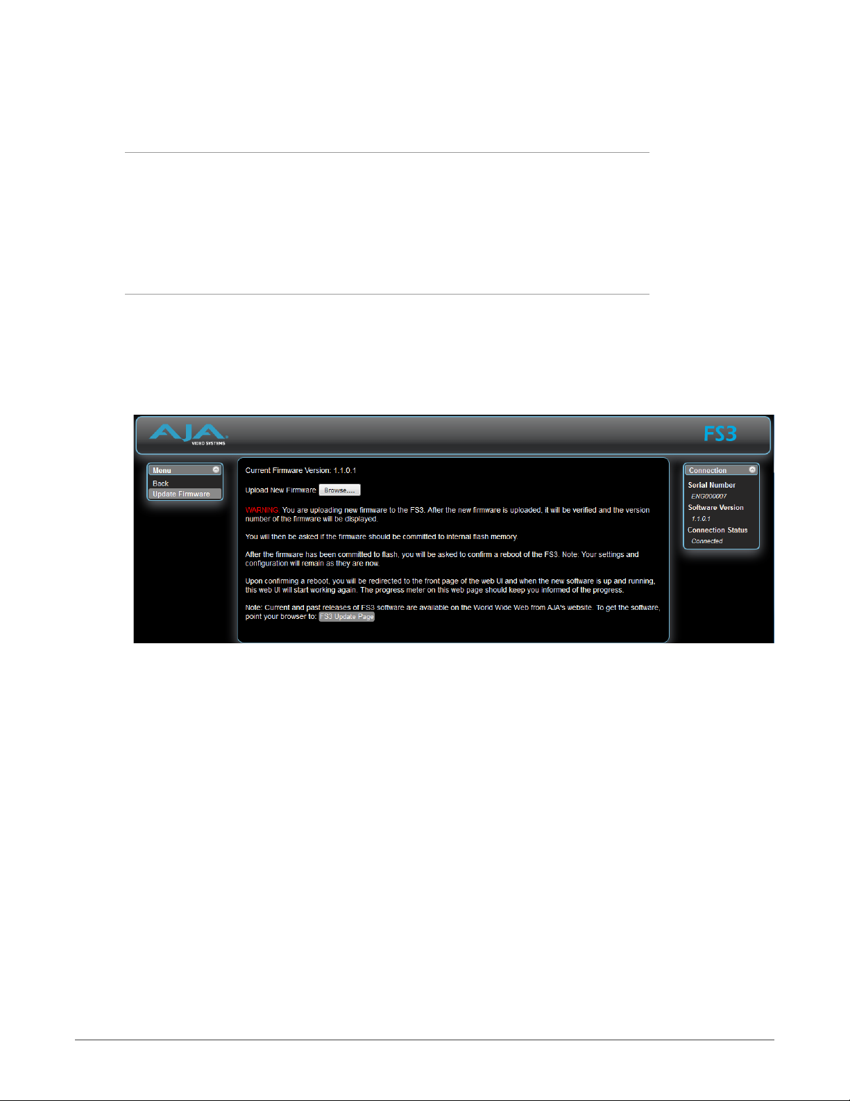
Uploading and Installing the Software to the FS3
Uploading and installing the software update requires a PC or Mac that can “see”
the FS3 via its Ethernet connection. Follow this procedure to install the software:
1. Point your browser at the FS3’s upgrade page by clicking on the Firmware
link at the bottom of the navigation box on the left-hand side of any FS3
web page.
Figure 9. Update Firmware Browser Screen
2. Click the Browse... button to nd and select the downloaded le. For
example: FS3_ver_1.1.0.1.bin contained in the le downloaded from AJA.
3. Click OK when asked if you want to Upload Firmware. The le uploads to
the FS3 and is tested for validity. Incomplete, corrupted, or non-FS3 les
are rejected. Wait for the procedure to complete—it will take only a few
minutes. Progress bars show upload progress.
4. Click Commit Uploaded Firmware when prompted after the upload is
nished. Progress bars show progress as the le is written to ash memory.
5. Click Restart FS3 with New Firmware to restart the FS3. This will take the
FS3 oine for a minute or two. During the restart, progress is shown in the
connection area in the upper right corner of the FS3 Status screen. After
restart, the FS3 will be running the new software.
6. Once these steps are complete, the FS3 will be running the software, and
the Software Version on the Status screen shows the new version number.
Check that the new software is running by bringing up the FS3 web page
again; the software version is displayed at the top of all FS3 web screens. If
the FS3 did not update successfully, run through the update steps again.
NOTE: The configuration of the FS3 prior to the upgrade is preserved. The unit returns to
service exactly as it was before the upgrade.
FS3 Frame Synchronizer/Converter v1.1r1 27 www.aja.com
If there is a power outage or glitch during the software download, the FS3 will
FMT ERR
ALARM
Line 4=Status/Legend
changes.
default value.
Menu Group Selection Buttons:
boot the older software version and you can restart the upgrade process. This
happens because the FS3 has been designed with a safety feature where an
internal “safe” copy of the previous software is retained in the event the updating
process fails.
System Cabling
System Video/Audio Cable Connections
When installing your system, you’ll make video and audio input/output
connections. These connectors are explained individually in Chapter 2.
GPI Connections
The FS3 has four GPI inputs and four GPI outputs. The GPI inputs and outputs
are electrically isolated from the power and ground on the FS3 frame. Electrical
isolation is provided for up to four pieces of external equipment.
See "GPI Pinouts" on page 93 for information on how to wire the GPI connector
to work with external devices that you want to use to control the FS3 or that you
want the FS3 to control.
Stand Alone Tests
The stand alone tests can be performed without a computer, using the FS3 front
panel controls and rear connections.
Press a button to select
a Menu Group in the display
Alphanumeric Display:
Line 1=Parameter
Line 2=Parameter value
Line 3=Status/Legend
The following procedures assume the FS3 is at factory defaults (taken from a
newly opened box). If not set to defaults, the FS3 may behave differently.
First Power Up
The following workflow powers up the FS3 and demonstrates some example
alarms.
Select knob:
Scrolls and
selects menus;
Push to undo
Adjust knob:
Changes
selected value;
Hold down for
Activity
Indicators:
VID IN
UFC
Proc Amp
Status Indicators:
REF, 2SI, LAN, EXT
Power and
Status Indicators:
PWR 1
PWR 2
ID
Setup
• Ensure the FS3 is completely disconnected (all video, audio, network, and
power connector ports are empty).
FS3 Frame Synchronizer/Converter v1.1r1 28 www.aja.com

Procedure
1. Connect both FS3 power cords to mains AC and allow time for the unit to
boot up. Observe the front panel LEDs.
• The ALARM LED will light red, indicating an alarm condition, and the REF
LED will be o. By default the FS3 is congured to operate genlocked to an
external reference signal.
2. Press the front panel STATUS button, then turn the SELECT knob to view
various Status menus.
• The Status menus will report No Input for the Video Processor video inputs
(the ports are disconnected), and the GEN (Genlock) parameter will report
Ref (congured for external reference) but will also report No Input or No
Ref.
Video Format Status screen Video Format Alarm Status screen
IN1 SDI 1 No Input
BKGD Black
GEN Ref No Input
OUT1 UHD59
3. Connect a 1080i59.95 HD tri-level sync reference signal to one of the FS3 Ref
Loop BNCs.
• The REF LED will light blue, indicating the FS3 is genlocked to an external
reference signal.
• The Status menu GEN parameters will report Ref and indicate the format of
the incoming reference signal or OK.
• The front panel ALARM LED will still be lighted red, however, because the
FS3 is not receiving a compatible video input. No Input and Incompat will
be reported for SDI 1.
IN1 SDI 1 Incompat
BKGD Black
GEN Ref No Ref
OUT1 UHD59
Video Format Status screen Video Format Alarm Status screen
IN1 SDI 1 No Input
BKGD Black
GEN Ref 1080i59
OUT1 UHD59
4. Connect a 1080i59.95 SDI video source to the SDI 1 input BNC.
• The front panel ALARM LED will go o, indicating no alarm condition exists
• The front panel will report 1080i59 and an OK status for SDI 1.
Video Format Status screen Video Format Alarm Status screen
IN1 SDI 1 1080i59
BKGD Black
GEN Ref 1080i59
OUT1 UHD59
5. Disconnect one of the power cords, leaving the other attached.
• The ALARM LED will light red, and the PWR LED of the power supply with
the removed cord will turn o.
6. Reconnect the power cable. The ALARM LED will turn o and the PWR LED
will light.
This workflow confirms the FS3 powers up successfully and reports reference and
power supply alarms.
NOTE: FS3 Reference, Power Supply, and Video Format alarms can be disabled, if
desired.
IN1 SDI 1 Incompat
BKGD Black
GEN Ref OK
OUT1 UHD59
IN1 SDI 1 OK
BKGD Black
GEN Ref OK
OUT1 UHD59
FS3 Frame Synchronizer/Converter v1.1r1 29 www.aja.com

Internal Test Signals To All Outputs
This workflow generates bars and tone and sends them to all the FS3 outputs.
This example uses the SDI 1-4 output connectors and a UltraHD video and
embedded audio monitor. In the following procedures, where the terms select
and adjust are used, turn the front panel SELECT and ADJUST knobs.
Setup
• Connect the FS3 SDI 1-4 output connectors to a UltraHD capable display
equipped with embedded audio monitoring.
Procedure
1. Press the VIDEO PROC button.
• Select 4 Output Mode, and adjust to Test Pattern.
• Select 21 Test Pattern and adjust to 75% Bars.
2. Press the AUDIO PROC button.
• Select 21 Global Audio Out and adjust to Sig Gen 1KHz.
You should now be able to see and hear the test signals on the UltraHD
display, and on any other devices connected to the FS3 outputs.
This workflow confirms the FS3 generates and outputs video and audio.
FS3 Processing Examples
In the following procedures, your exact actions depend on which FS3 interface
you are using.
• On the front panel interface, press the indicated Menu Group Selection
button and then turn the SELECT and ADJUST knobs to choose the parameter
and change the setting. The Front Panel menu numbers are included in the
procedures.
• On the web browser interface, use your mouse to select the name of the Menu
Screen and then choose the parameter and setting using the drop down list or
slider. Menu numbers are not present on the FS3 web pages.
HD to UltraHD 4-Link Quadrant 59.94
The following workflow demonstrates up-converting an HD SDI input to a
UltraHD SDI 4-Link Quadrant (Square Division) output. This example uses a 1080i
59.94 input and reference, and generates a UltraHDp59.94 output.
Setup
• Ensure the FS3 is receiving a valid reference signal. Connect a 1080i59.95 HD
tri-level sync signal to one of the Ref Loop BNC connectors, and terminate
the other Ref Loop BNC connector (either with a terminator or by connecting
to terminated equipment). Once connected the FS3 front panel REF LED will
light.
• Connect a 1080i59.94 HD SDI signal to the SDI1 input on the rear of the FS3.
Once connected the FS3 front panel VID IN LED will light.
• Connect the four FS3 SDI1-4 video output connectors to a compatible UltraHD
monitor.
NOTE: Alternatively, you can monitor each UltraHD quadrant at full resolution on a
standard SDI monitor by connecting each of the four outputs individually.
FS3 Frame Synchronizer/Converter v1.1r1 30 www.aja.com
 Loading...