

Page 1

Introduction
FS2
Quick Start Guide
This Quick Start Guide provides a basic overview of FS2 system connections and
configuration. The FS2 can be extremely simple to use, because of its ability
to detect incoming signal formats and automatically apply the correct video
processing for the selected output format. However, the FS2 is also extremely
powerful and can be flexibly configured to perform a wide variety of tasks.
This Quick Start Guide is designed to help you get your FS2 up and running for
the first time, and confirm it is operating properly. It also provides step-by-step
instructions that demonstrate a FS2 signal processing example.
For additional information, please see the FS2 Installation and Operation Guide
available on the AJA website.
Installation Summary
1. Unpack the shipping box, inspect and inventory the contents, and read the
late-breaking news sheet, if any.
2. Install any optional SFP I/O modules by sliding them into the SFP cages in
the back. Use only AJA approved modules.
NOTE: The "Stand Alone Tests" on page 2 can be performed with the FS2 sitting on a
bench to test system operation before physically installing the unit.
3. Mount the physical chassis: front rack, rear rack, or deskmount—1 RU x 17.5
inches (44.45 cm) x 16 inches (40.65 cm). Do not block air ow through the
side vents.
4. Make signal I/O connections to the FS2 back panel as shown in Figure 1.
Published June 26, 2017
FS2 Quick Start Guide v2.1 1 www.aja.com
Page 2
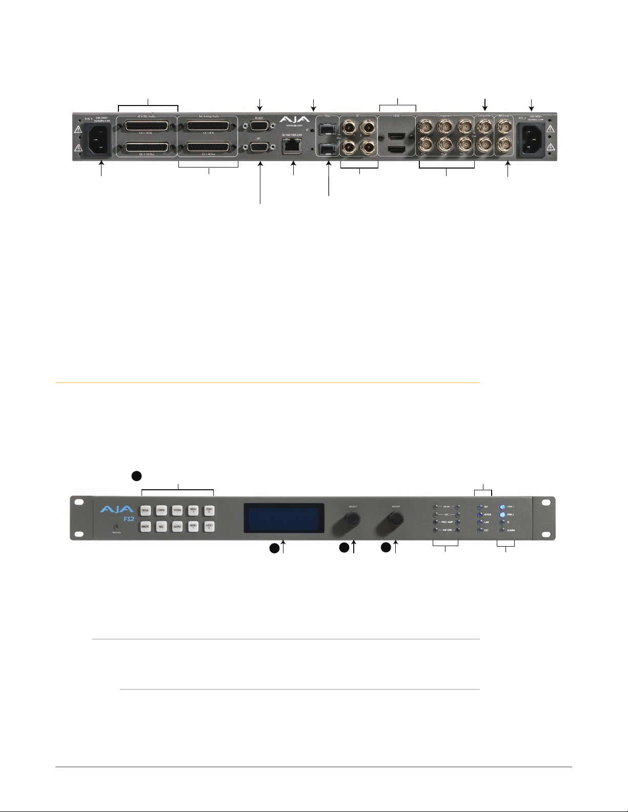
Figure 1. FS2 Rear Panel
AC Power #2
AES/EBU Digital
Audio In/Out
Channels 1 through 16
DB-25F Connectors
AC Power #1
Autosensing
100 to 240VAC
50/60Hz
Analog Audio In/Out
Channels 1 through 8
DB-25F Connectors
(uses Tascam-style
5. Connect one or two power cords to the FS2 and mains AC (100-240 VAC,
50/60 Hz, 55 Watts). For redundancy, use both cords and connect them to
separate branch circuits. The FS2 power supply is autosensing and adjusts
to the available power.
6. Connect your computer to the FS2 using a CAT5 Ethernet cable to the FS2
RJ45 10/100/1000 Ethernet LAN connector. You can connect directly or via
a network device such as a switch, hub, bridge, etc. The FS2 automatically
senses and adjusts to either a straight-through or crossover cable.
Stand Alone Tests
cable)
(Future Use)
GPI 15-pin
DB-15F Connector
10/100/1000
RJ45 Ethernet
LAN Connector
ID
LED
Serial Digital
Fiber In/Out
(3G/SD/HD)
Serial Digital
In/Out BNC
(3G/SD/HD)
HDMI
In/Out
Component
YPbPr and
RGB or
Composite (v1.1)
In/Out
BNC
Autosensing
Composite
In/Out BNC
Use 75-ohm terminator
or downstream equipment.
100 to 240VAC
50/60Hz
External Reference
I/O with looping
BNC connectors.
on unused connector
1
First Power Up
Setup
The stand alone tests can be performed without a computer, using the FS2 front
panel controls and rear connections. The following procedures assume the FS2 is
at factory defaults (taken from a newly opened box). If not set to defaults, the FS2
may behave differently.
Figure 2. AJA FS2 Front Panel Controls and Indicators
Menu Group Selection Buttons:
Press a button to select
a Menu Group in the display
2
Alphanumeric Display:
Line 1=Parameter
Line 2=Parameter value
Line 3=Status/Legend
Line 4=Status/Legend
3
Select knob:
Scrolls and
selects menus;
Push to undo
changes.
4
Adjust knob:
Changes
selected value;
Hold down for
default value.
Proc Amp Ch 1/2
FMT ERR Ch 1/2
The following workflow powers up a default FS2 and demonstrates some
example alarms.
• Ensure the FS2 is completely disconnected (all video, audio, network, and
power connector ports are empty).
Activity
Indicators:
VID In Ch 1/2
UFC Ch 1/2
Ref, Keyer, LAN, EXT
Status Indicators:
Power and Status
Indicators:
Pwr 1
Pwr 2
ID
Alarm
FS2 Quick Start Guide v2.1 2 www.aja.com
Page 3

Procedure
1. Connect both FS2 power cords to mains AC and allow time for the unit to
boot up. Observe the front panel LEDs.
• The REF LED will light red, indicating an alarm condition. By default the FS2
is congured to operate genlocked to an external reference signal.
2. Press the front panel STATUS button, then turn the SELECT knob to view
various Status menus.
• The Status menu for Video Processor 1 will report No Input for IN1, the
port is disconnected), and the GEN (Genlock) parameter will report Ref
(congured for external reference) but will also report No Input.
Video Format Status screen Video Format Alarm Status screen
IN1 SDI 1 No Input
BKGD Black 525i59
GEN Ref No Input
OUT1 1080i59
3. Connect a sync reference signal to one of the FS2 Ref Loop BNCs, and
connect a 75 ohm terminator to the other Ref BNC.
• The REF LED will light blue, indicating the FS2 is genlocked to an external
reference signal.
• The Status menu GEN parameters will report Ref and indicate the format of
the incoming reference signal or OK.
• However, because the FS2 is still not receiving a compatible video input, No
Input, will be reported for IN1.
Video Format Status screen Video Format Alarm Status screen
IN1 SDI 1 No Input
BKGD Black
GEN Ref 1080i59
OUT1 525i59
4. Connect a 1080i59.94 SDI video source to the SDI 1 input BNC.
• The front panel will report 1080i59 and an OK status for SDI 1. This indicates
no alarm condition exists.
Video Format Status screen Video Format Alarm Status screen
IN1 SDI 1 1080i59
BKGD Black 1080i59
GEN Ref 1080i59
OUT1 1080i59
5. Disconnect one of the power cords, leaving the other attached.
• The front panel PWR LED will light red for the power supply with the
removed cord.
• The PS status will report PS1 (or 2) OFF
6. Reconnect the power cable. The PWR LED for that power supply will light
blue and the power supply status will report OK.
This workflow confirms the FS2 powers up successfully and reports reference and
power supply alarms.
NOTE: FS2 Reference, Power Supply, and Video Format alarms can be disabled, if
desired. This will prevent the LEDs from going red, but will not affect front panel
status displays.
IN1 SDI 1 OK
BKGD Black OK
GEN Ref No Ref
Rate 525i59
IN1 SDI 1 OK
BKGD Black OK
GEN Ref OK
Rate 525i59
IN1 SDI 1 OK
BKGD Black OK
GEN Ref OK
OUT1 1080i59
FS2 Quick Start Guide v2.1 3 www.aja.com
Page 4

Internal Test Signals
This workflow generates bars and tone and routes them to an FS2 video and
audio output. This example uses the SDI 1 and AES output connectors, an SDI
video monitor, and an AES audio monitor.
NOTE: In the following procedures, where the terms select and adjust are used, turn the
front panel SELECT and ADJUST knobs.
Setup
• Connect the FS2 SDI 1 output BNC connector to an SDI video display with a
BNC cable.
• Connect the FS2 AES/EBU output DB25 connector to an AES audio monitor
using a standard TASCAM pinout cable (customer supplied). Separate DB25
connectors carry all 8 AES digital audio pairs (16 audio signals), one connector
for input and one for output. Turn the output gain of the audio monitor to a
low level.
Procedure
1. Press the VIDEO 1 button.
• Select 2 Output Format and adjust to a signal compatible with your SDI
monitor (for example, 1080i59.95).
• Select 3 Video Output Mode and adjust to Test Pattern.
• Select 2 Test Pattern and adjust to 75% Bars.
• Select 21 Test Pattern Video and adjust to 75% Bars.
2. Press the AUDIO 1 button.
• Select 4 Audio Signal Gen and adjust to Sig Gen 400KHz.
You should now be able to see the test signal on the SDI Monitor display, and hear
the audio on the AES monitor.
This workflow confirms the FS2 generates and outputs video and audio.
FS2 Network Setup
The following instructions summarize ways to configure the FS2 to communicate
with a computer directly or over a network.
FS2 Default Network Settings
The FS2 ships from the factory set for DHCP networking, and can be manually
reset to the following default network settings:
IP Address 192.168 .0.2
Subnet Mask 255.255.255.0
Gateway 192.168 .0.1
Networking Using DHCP or Default Static IP
The FS2 factory default configuration automatically looks for a DHCP server to
issue an IP address. If your network includes a DHCP server, plug the FS2 into the
network and connect with the unit as follows:
1. Press the CONFIG button.
FS2 Quick Start Guide v2.1 4 www.aja.com
Page 5

2. Turn the SELECT knob to navigate to the Status menu that has the name of
the FS2 at the top (default is “aja-FS2”). Note the DHCP-supplied IP address
shown.
3. With your laptop or desktop computer connected to the same LAN as the
FS2 and DHCP enabled, type the IP address you noted on the FS2’s display
into the browser address eld and press Enter. You should now see the FS2’s
browser Status screen.
If the FS2 cannot get an address from the network DHCP server, the FS2 will
automatically use a preset factory static IP address of 192.168.0.2. You can access
the FS2 using the default static address as follows:
1. Set your computer’s IP address to whatever address you prefer in the
192.168.0 (classC) network.
2. Set the computer’s Subnet mask to 255.255.255.0 (most PCs default to the
proper netmask when the address is set).
3. Set the gateway address, if used, to match the FS2 default: 192.168.0.1.
Alternatively, change the FS2 gateway address to match your gateway:
A. Press CONFIG, turn SELECT to 2.4 Default Gateway, push and then turn
ADJUST to change the rst group of digits.
B. Turn SELECT to advance to the next set of numbers, and turn ADJUST to set
these numbers.
C. Continue using SELECT and ADJUST to set the full address.
D. When nished, push ADJUST momentarily to save the address.
5. Run a browser on the computer and type “192.168.0.2” (the factory static IP
address). You should now see the FS2’s browser status screen.
Networking the FS2 Using Your Own Static IP
If you don’t want to use DHCP or the default static IP address, you can set your
own static IP address:
1. Select the CONFIG button and use the SELECT knob to navigate to
parameter 2.1 IP CONFIG. Use the ADJUST knob to select Static.
2. Turn SELECT to navigate to parameter 2.2 IP ADDRESS. The display shows
the default static IP address: 192.168.0.2.
3. Change the IP address as follows.
A. Push the ADJUST knob momentarily so that the rst octet (set of numbers)
blinks, and then turn ADJUST to change the numbers.
B. Turn SELECT to advance to the next set of numbers, and turn ADJUST to set
these numbers.
C. Continue using SELECT and ADJUST to set the full address.
D. When nished, push ADJUST momentarily to save the address.
5. Turn SELECT to advance to 2.3 Subnet Mask. Use the SELECT and ADJUST
knobs as in the previous step to set the desired subnet mask.
6. Turn SELECT to advance to 2.4 Default Gateway. Use the SELECT and ADJUST
knobs as in the previous step to set the desired gateway address.
7. Run a browser on the computer and type in the IP address you set for the
FS2. You should now see the FS2’s Status screen.
Web Browser Menu Summary
Figure 4 on page 7 summarizes web browser menu operation. The settings
generally correspond to the front panel display parameters, providing you
FS2 Quick Start Guide v2.1 5 www.aja.com
Page 6

Menu of FS2
Screens:
Click a screen’s
name to display that
screen.
FS2 Alarms
two methods of controlling the FS2. To see the equivalent front panel display
parameter number, hover the cursor over a setting.
Figure 3. FS2 Web Interface, Main Status Screen
FS2 Status and Menu Display Area System info, and FS2 Systems on the network
FS2 Signal Processing Example
Sidebar Video
The following workflow shows how to create sidebar edges filled with video.
Setup
• SDI 1 Input feeds Processor 1 foreground.
Use an SD 525 input on SDI 1; it will be upconverted to 1080i59.
• SDI 2 Input feeds Processor 2, which will provide Processor 1 background.
Use an HD input signal in SDI2.
• Processor 1 feeds SDI1 Output (center video with sidebar video).
• Processor 2 feeds SDI2 Output (showing the sidebar video signal alone).
The parameter settings are:
• Video 1 Input set to SDI 1.
• Output Format set to 1080i59.94.
• Video Output Mode set to Normal.
• Upconvert Mode set to 4x3 Pillar.
• Custom Size/Pos set to O.
• Background Fill set to Video 2.
FS2 Quick Start Guide v2.1 6 www.aja.com
Page 7

Procedure
1. Press the Video 1 button.
• Select 1 Video 1 Input, and adjust to SDI 1.
• Select 2 Output Format, and adjust to 1080i59.94.
• Select 3 Video Output Mode, and adjust to Normal.
• Select 6 Upconvert Mode, and adjust to 4x3 Pillar.
• Select 4 Background Fill, and adjust sidebar video to Video 2.
• Select 9 Sidebar Edge, and adjust sidebar position as you prefer.
• Select 13.0 Custom Size/Pos, and adjust to O.
2. Press the Video 2 button.
• Select 1 Video 2 Input and adjust to SDI2.
• Select 2 Output Format and adjust to 1080i59.94.
Figure 4. Sidebar Video Result
FS2 Quick Start Guide v2.1 7 www.aja.com
 Loading...