

www.aja.com
Installation and Operation
Guide
Because it matters.
Published: 3/2/2010
(Software Version 2.1.2.54)

ii
Trademarks
®
AJA
, KONA
trademarks of AJA Video, Inc.
TASCAM
®
Dolby laboratories.
All other trademarks are the property of their respective holders.
Notice
Copyright © 2010 AJA Video, Inc. All rights reserved. All information in this manual is subject to
change without notice. No part of the document may be reproduced or transmitted in any form,
or by any means, electronic or mechanical, including photocopying or recording, without the
express written permission of AJA Inc.
FCC Emission Information
This equipment has been tested and found to comply with the limits for a Class A digital device,
pursuant to Part 15 of the FCC Rules. These limits are designed to provide reasonable protection
against harmful interference when the equipment is operated in a commercial environment. This
equipment generates, uses and can radiate radio frequency energy and, if not installed and used in
accordance with the instruction manual, may cause harmful interference to radio
communications. Operation of this equipment in a residential area is likely to cause harmful
interference in which case the user will be required to correct the interference at his own expense.
Changes or modifications not expressly approved by AJA Video can effect emission compliance
and could void the user’s authority to operate this equipment.
®
, and XENA
®
are registered trademarks of AJA Video, Inc. Io HD
is a registered trademark of TEAC Corporation. Dolby
™
®
is a registered trademark of
and Io
™
are
Contacting Support
To contact AJA Video for sales or support, use any of the following methods:
180 Litton Drive, Grass Valley, CA. 95945 USA
Telephone: +1.800.251.4224 or +1.530.274.2048
Fax: +1.530.274.9442
Web: http://www.aja.com
Support Email: support@aja.com
Sales Email: sales@aja.com

Limited Warranty
FS1 Installation and Operation Manual — Limited Warranty
AJA Video warrants that this product will be free from defects in materials and workmanship
for a period of five years from the date of purchase. If a product proves to be defective during
this warranty period, AJA Video, at its option, will either repair the defective product without
charge for parts and labor, or will provide a replacement in exchange for the defective product.
In order to obtain service under this warranty, you the Customer, must notify AJA Video of
the defect before the expiration of the warranty period and make suitable arrangements for the
performance of service. The Customer shall be responsible for packaging and shipping the
defective product to a designated service center nominated by AJA Video, with shipping
charges prepaid. AJA Video shall pay for the return of the product to the Customer if the
shipment is to a location within the country in which the AJA Video service center is located.
Customer shall be responsible for paying all shipping charges, insurance, duties, taxes, and
any other charges for products returned to any other locations.
This warranty shall not apply to any defect, failure or damage caused by improper use or
improper or inadequate maintenance and care. AJA Video shall not be obligated to furnish
service under this warranty a) to repair damage resulting from attempts by personnel other
than AJA Video representatives to install, repair or service the product, b) to repair damage
resulting from improper use or connection to incompatible equipment, c) to repair any
damage or malfunction caused by the use of non-AJA Video parts or supplies, or d) to service
a product that has been modified or integrated with other products when the effect of such a
modification or integration increases the time or difficulty of servicing the product.
THIS WARRANTY IS GIVEN BY AJA VIDEO IN LIEU OF ANY OTHER
WARRANTIES, EXPRESS OR IMPLIED. AJA VIDEO AND ITS VENDORS
DISCLAIM ANY IMPLIED WARRANTIES OF MERCHANTABILITY OR FITNESS
FOR A PARTICULAR PURPOSE. AJA VIDEO’S RESPONSIBILITY TO REPAIR OR
REPLACE DEFECTIVE PRODUCTS IS THE WHOLE AND EXCLUSIVE REMEDY
PROVIDED TO THE CUSTOMER FOR ANY INDIRECT, SPECIAL, INCIDENTAL
OR CONSEQUENTIAL DAMAGES IRRESPECTIVE OF WHETHER AJA VIDEO OR
THE VENDOR HAS ADVANCE NOTICE OF THE POSSIBILITY OF SUCH
DAMAGES.
1
iii
Important Safety Instructions
Warning:
threat to personal safety.
WARNING
Caution:
informational notices.
CAUTION
Warning:
1. Read these instructions
2. Keep these instructions.
3. Heed all warnings.
WARNING
4. Follow all instructions.
5. Do not use this apparatus near water.
6. Clean only with a dry cloth.
7. Do not block any ventilation openings. Install in accordance with the
manufacturer ’ s instructions.
8. Do not install near any heat sources such as radiators, heat registers, stoves, or
other apparatus (including amplifiers) that produce heat.
This symbol, when used in the manual, indicates a serious risk or
This symbol, when used in the manual, indicates important safety and
(continued next page)
iv
WARNING
9. Do not defeat the safety purpose of the polarized or grounding-type plug. A
polarized plug has two blades with one wider than the other. A grounding plug
has two blades and a third grounding prong. The wide blade or the third prong are
provided for your safety. If the provided plug does not fit your outlet, consult an
electrician for replacement of the obsolete outlet.
10. Protect the power cords from being walked on or pinched, particularly at plugs,
convenience receptacles, and the point where they exit from the apparatus.
11. Only use attachments/accessories specified by the manufacturer.
12. Unplug this apparatus during lightning storms or when unused for long periods of time.
13. Refer all servicing to qualified service personnel. Servicing is required when the
apparatus has been damaged in any way, such as power-supply cord or plug is damaged,
liquid has been spilled, or objects have fallen into the apparatus, the apparatus has been
exposed to rain or moisture, does not operate normally, or has been dropped.
WARNING
Warning:
Hazardous voltage is present inside the unit, presenting a risk of electric shock or serious
personal injury. Opening the chassis will void the warranty unless performed by an AJA
service center or licensed facility. Remove the two supplied AC line cords from mains power
when moving the unit. Do not defeat the safety purpose of the grounding-type plug.
Warning:
supplies to separate branch circuits.
Do not open the chassis. There are no user-serviceable parts inside.
To meet safety regulations for leakage current, connect the FS1 dual power

FS1 Installation and Operation Manual — Table of Contents
Table of Contents
Trademarks . . . . . . . . . . . . . . . . . . . . . . . . . . . . . . . . . . . . . . . . . . . . . . . . . . . . . . . . . . . . . . . . . . ii
Notice . . . . . . . . . . . . . . . . . . . . . . . . . . . . . . . . . . . . . . . . . . . . . . . . . . . . . . . . . . . . . . . . . . . . . . . ii
FCC Emission Information . . . . . . . . . . . . . . . . . . . . . . . . . . . . . . . . . . . . . . . . . . . . . . . . . . . . . . . ii
Contacting Support . . . . . . . . . . . . . . . . . . . . . . . . . . . . . . . . . . . . . . . . . . . . . . . . . . . . . . . . . . . . . ii
Limited Warranty . . . . . . . . . . . . . . . . . . . . . . . . . . . . . . . . . . . . . . . . . . . . . . . . . . . . . . . . . . . . . iii
Important Safety Instructions . . . . . . . . . . . . . . . . . . . . . . . . . . . . . . . . . . . . . . . . . . . . . . . . . . . . iii
Table of Contents . . . . . . . . . . . . . . . . . . . . . . . . . . . . . . . . . . . . . . . . . . . . . . . . . . . . . . . . . . . . . . 1
Chapter 1: Introduction
Overview . . . . . . . . . . . . . . . . . . . . . . . . . . . . . . . . . . . . . . . . . . . . . . . . . . . . . . . . . . . . . . . . . . . . . 1
Features . . . . . . . . . . . . . . . . . . . . . . . . . . . . . . . . . . . . . . . . . . . . . . . . . . . . . . . . . . . . . . . . . . . . . . 1
FS1 Front Panel Control . . . . . . . . . . . . . . . . . . . . . . . . . . . . . . . . . . . . . . . . . . . . . . . . . . . . . . . . . 2
Remote Web Browser Control of FS1 via Ethernet . . . . . . . . . . . . . . . . . . . . . . . . . . . . . . . . . . . . . 2
SNMP Interface . . . . . . . . . . . . . . . . . . . . . . . . . . . . . . . . . . . . . . . . . . . . . . . . . . . . . . . . . . . . . . . 3
Block Diagram . . . . . . . . . . . . . . . . . . . . . . . . . . . . . . . . . . . . . . . . . . . . . . . . . . . . . . . . . . . . . . . . 3
Block Diagram Description . . . . . . . . . . . . . . . . . . . . . . . . . . . . . . . . . . . . . . . . . . . . . . . . . . . 3
What’s In The Box? . . . . . . . . . . . . . . . . . . . . . . . . . . . . . . . . . . . . . . . . . . . . . . . . . . . . . . . . . . . . 4
In This Manual . . . . . . . . . . . . . . . . . . . . . . . . . . . . . . . . . . . . . . . . . . . . . . . . . . . . . . . . . . . . . . . . 5
1
T-1
Chapter 2: Controls and Indicators
Controls and Indicators . . . . . . . . . . . . . . . . . . . . . . . . . . . . . . . . . . . . . . . . . . . . . . . . . . . . . . . . . . 7
Front Panel . . . . . . . . . . . . . . . . . . . . . . . . . . . . . . . . . . . . . . . . . . . . . . . . . . . . . . . . . . . . . . . . . . . 7
Alphanumeric Display . . . . . . . . . . . . . . . . . . . . . . . . . . . . . . . . . . . . . . . . . . . . . . . . . . . . . . . 8
Status Display . . . . . . . . . . . . . . . . . . . . . . . . . . . . . . . . . . . . . . . . . . . . . . . . . . . . . . . . . . . . . 9
Controlling the FS1—Using the Select and Adjust Buttons . . . . . . . . . . . . . . . . . . . . . . . . . . 10
Remote Control . . . . . . . . . . . . . . . . . . . . . . . . . . . . . . . . . . . . . . . . . . . . . . . . . . . . . . . . . . . 11
Indicator Descriptions . . . . . . . . . . . . . . . . . . . . . . . . . . . . . . . . . . . . . . . . . . . . . . . . . . . . . . 11
Activity Indicators . . . . . . . . . . . . . . . . . . . . . . . . . . . . . . . . . . . . . . . . . . . . . . . . . . . . . . . 11
Power and Status Indicators . . . . . . . . . . . . . . . . . . . . . . . . . . . . . . . . . . . . . . . . . . . . . . . 12
About video and format compatibility . . . . . . . . . . . . . . . . . . . . . . . . . . . . . . . . . . . . . . . . . . 13
Rear Panel . . . . . . . . . . . . . . . . . . . . . . . . . . . . . . . . . . . . . . . . . . . . . . . . . . . . . . . . . . . . . . . . . . 14
About Inputs and Outputs . . . . . . . . . . . . . . . . . . . . . . . . . . . . . . . . . . . . . . . . . . . . . . . . . . . 14
Connectors . . . . . . . . . . . . . . . . . . . . . . . . . . . . . . . . . . . . . . . . . . . . . . . . . . . . . . . . . . . . . . . . . . 14
Connector Descriptions . . . . . . . . . . . . . . . . . . . . . . . . . . . . . . . . . . . . . . . . . . . . . . . . . . . . . 15
8 Channel AES/EBU Audio Inputs And Outputs . . . . . . . . . . . . . . . . . . . . . . . . . . . . . . . 15
Analog 8 Channel Audio . . . . . . . . . . . . . . . . . . . . . . . . . . . . . . . . . . . . . . . . . . . . . . . . . . 15
RS-422 Port . . . . . . . . . . . . . . . . . . . . . . . . . . . . . . . . . . . . . . . . . . . . . . . . . . . . . . . . . . . 15
GPI . . . . . . . . . . . . . . . . . . . . . . . . . . . . . . . . . . . . . . . . . . . . . . . . . . . . . . . . . . . . . . . . . . 15
LAN . . . . . . . . . . . . . . . . . . . . . . . . . . . . . . . . . . . . . . . . . . . . . . . . . . . . . . . . . . . . . . . . . 16
Component (YPbPr/RGB) . . . . . . . . . . . . . . . . . . . . . . . . . . . . . . . . . . . . . . . . . . . . . . . . 16
S-Video (Y/C) . . . . . . . . . . . . . . . . . . . . . . . . . . . . . . . . . . . . . . . . . . . . . . . . . . . . . . . . . . 16
Composite NTSC/PAL . . . . . . . . . . . . . . . . . . . . . . . . . . . . . . . . . . . . . . . . . . . . . . . . . . . 16
Reference Video (looping) . . . . . . . . . . . . . . . . . . . . . . . . . . . . . . . . . . . . . . . . . . . . . . . . . 17
Examples of permissible reference video signals: . . . . . . . . . . . . . . . . . . . . . . . . . . . . . . . . 17

T-2
Chapter 3: Installation
Installation Overview . . . . . . . . . . . . . . . . . . . . . . . . . . . . . . . . . . . . . . . . . . . . . . . . . . . . . . . . . . .19
Unpacking . . . . . . . . . . . . . . . . . . . . . . . . . . . . . . . . . . . . . . . . . . . . . . . . . . . . . . . . . . . . . . . . . . .21
Shipping Box Contents . . . . . . . . . . . . . . . . . . . . . . . . . . . . . . . . . . . . . . . . . . . . . . . . . . . . . .21
The FS1 Chassis—Rackmount or Place on a Desk . . . . . . . . . . . . . . . . . . . . . . . . . . . . . . . . . . . . .21
Physical Requirements . . . . . . . . . . . . . . . . . . . . . . . . . . . . . . . . . . . . . . . . . . . . . . . . . . . . . .21
Network Connection . . . . . . . . . . . . . . . . . . . . . . . . . . . . . . . . . . . . . . . . . . . . . . . . . . . . . . . . . . .22
TCP/IP Information You’ll Need . . . . . . . . . . . . . . . . . . . . . . . . . . . . . . . . . . . . . . . . . . . . . .22
Networking the FS1 via DHCP . . . . . . . . . . . . . . . . . . . . . . . . . . . . . . . . . . . . . . . . . . . . . . .22
Networking the FS1 using a Static IP Address . . . . . . . . . . . . . . . . . . . . . . . . . . . . . . . . . . . . 23
Networking the FS1 using the Factory Default IP . . . . . . . . . . . . . . . . . . . . . . . . . . . . . . . . . .24
Test the FS1 Network Connection with “Ping” . . . . . . . . . . . . . . . . . . . . . . . . . . . . . . . . . . . . . . .25
Mac Ping Procedure . . . . . . . . . . . . . . . . . . . . . . . . . . . . . . . . . . . . . . . . . . . . . . . . . . . . . . . .25
Windows PC Ping Procedure . . . . . . . . . . . . . . . . . . . . . . . . . . . . . . . . . . . . . . . . . . . . . . . . .25
Controlling the FS1 from a web-browser . . . . . . . . . . . . . . . . . . . . . . . . . . . . . . . . . . . . . . . . . . . .25
Installing The Latest Software . . . . . . . . . . . . . . . . . . . . . . . . . . . . . . . . . . . . . . . . . . . . . . . . . . . .26
Download the Latest FS1 Software . . . . . . . . . . . . . . . . . . . . . . . . . . . . . . . . . . . . . . . . . . . . .26
Unpack the Software . . . . . . . . . . . . . . . . . . . . . . . . . . . . . . . . . . . . . . . . . . . . . . . . . . . . . . . .26
Uploading and Installing the Software to the FS1 . . . . . . . . . . . . . . . . . . . . . . . . . . . . . . . . . .26
GPI Connections . . . . . . . . . . . . . . . . . . . . . . . . . . . . . . . . . . . . . . . . . . . . . . . . . . . . . . . . . . . . . .27
Cabling the System . . . . . . . . . . . . . . . . . . . . . . . . . . . . . . . . . . . . . . . . . . . . . . . . . . . . . . . . . . . .28
Where to Place FS1 . . . . . . . . . . . . . . . . . . . . . . . . . . . . . . . . . . . . . . . . . . . . . . . . . . . . . . . . .28
Power Requirements . . . . . . . . . . . . . . . . . . . . . . . . . . . . . . . . . . . . . . . . . . . . . . . . . . . . . . . .28
System Video/Audio Cable Connections . . . . . . . . . . . . . . . . . . . . . . . . . . . . . . . . . . . . . . . . .28
FS1 Audio Level Choices—Pro or Consumer . . . . . . . . . . . . . . . . . . . . . . . . . . . . . . . . . . . . .28
How Do Audio Levels Settings Relate to Nominal Levels? . . . . . . . . . . . . . . . . . . . . . . . . .29
Chapter 4: Parameter Menus
Controlling the FS1 via Its Front Panel Parameter Menus . . . . . . . . . . . . . . . . . . . . . . . . . . . . . . .31
1.1 Output Format . . . . . . . . . . . . . . . . . . . . . . . . . . . . . . . . . . . . . . . . . . . . . . . . . . . . . . . . . . . .32
1.2 SDI 2 Out Format . . . . . . . . . . . . . . . . . . . . . . . . . . . . . . . . . . . . . . . . . . . . . . . . . . . . . . . . . .33
1.3 Component Out . . . . . . . . . . . . . . . . . . . . . . . . . . . . . . . . . . . . . . . . . . . . . . . . . . . . . . . . . . .33
2.1 Video Input . . . . . . . . . . . . . . . . . . . . . . . . . . . . . . . . . . . . . . . . . . . . . . . . . . . . . . . . . . . . . . .34
2.2 Audio Input . . . . . . . . . . . . . . . . . . . . . . . . . . . . . . . . . . . . . . . . . . . . . . . . . . . . . . . . . . . . . . .35
2.11 Audio Map Ch1 . . . . . . . . . . . . . . . . . . . . . . . . . . . . . . . . . . . . . . . . . . . . . . . . . . . . . . . . . . .36
2.12 Audio Map Ch2 . . . . . . . . . . . . . . . . . . . . . . . . . . . . . . . . . . . . . . . . . . . . . . . . . . . . . . . . . . .37
2.13 Audio Map Ch3 . . . . . . . . . . . . . . . . . . . . . . . . . . . . . . . . . . . . . . . . . . . . . . . . . . . . . . . . . . .37
2.14 Audio Map Ch4 . . . . . . . . . . . . . . . . . . . . . . . . . . . . . . . . . . . . . . . . . . . . . . . . . . . . . . . . . . .37
2.15 Audio Map Ch5 . . . . . . . . . . . . . . . . . . . . . . . . . . . . . . . . . . . . . . . . . . . . . . . . . . . . . . . . . . .37
2.16 Audio Map Ch6 . . . . . . . . . . . . . . . . . . . . . . . . . . . . . . . . . . . . . . . . . . . . . . . . . . . . . . . . . . .37
2.17 Audio Map Ch7 . . . . . . . . . . . . . . . . . . . . . . . . . . . . . . . . . . . . . . . . . . . . . . . . . . . . . . . . . . .37
2.18 Audio Map Ch8 . . . . . . . . . . . . . . . . . . . . . . . . . . . . . . . . . . . . . . . . . . . . . . . . . . . . . . . . . . .37
2.21 Audio Map Ch 1/2 . . . . . . . . . . . . . . . . . . . . . . . . . . . . . . . . . . . . . . . . . . . . . . . . . . . . . . . . .38
2.22 Audio Map Ch 3/4 . . . . . . . . . . . . . . . . . . . . . . . . . . . . . . . . . . . . . . . . . . . . . . . . . . . . . . . . .38
2.23 Audio Map Ch 5/6 . . . . . . . . . . . . . . . . . . . . . . . . . . . . . . . . . . . . . . . . . . . . . . . . . . . . . . . . .38
2.24 Audio Map Ch 7/8 . . . . . . . . . . . . . . . . . . . . . . . . . . . . . . . . . . . . . . . . . . . . . . . . . . . . . . . . .38
3.1 Component In Format . . . . . . . . . . . . . . . . . . . . . . . . . . . . . . . . . . . . . . . . . . . . . . . . . . . . . . .39
3.2 Component Out Format . . . . . . . . . . . . . . . . . . . . . . . . . . . . . . . . . . . . . . . . . . . . . . . . . . . . .39

FS1 Installation and Operation Manual — Table of Contents
3.3 Frame Rate . . . . . . . . . . . . . . . . . . . . . . . . . . . . . . . . . . . . . . . . . . . . . . . . . . . . . . . . . . . . . . . 39
3.4 NTSC Standard . . . . . . . . . . . . . . . . . . . . . . . . . . . . . . . . . . . . . . . . . . . . . . . . . . . . . . . . . . . 39
4.1 Analog Audio Std. . . . . . . . . . . . . . . . . . . . . . . . . . . . . . . . . . . . . . . . . . . . . . . . . . . . . . . . . . . 40
4.2 Audio Delay (mS) . . . . . . . . . . . . . . . . . . . . . . . . . . . . . . . . . . . . . . . . . . . . . . . . . . . . . . . . . . 40
4.3 Embed Audio Out . . . . . . . . . . . . . . . . . . . . . . . . . . . . . . . . . . . . . . . . . . . . . . . . . . . . . . . . . 40
4.4 Sample Rate Convert . . . . . . . . . . . . . . . . . . . . . . . . . . . . . . . . . . . . . . . . . . . . . . . . . . . . . . . 41
4.5 Audio Follow Video . . . . . . . . . . . . . . . . . . . . . . . . . . . . . . . . . . . . . . . . . . . . . . . . . . . . . . . . 41
4.6 AFV Memory . . . . . . . . . . . . . . . . . . . . . . . . . . . . . . . . . . . . . . . . . . . . . . . . . . . . . . . . . . . . . 42
5.1 Upconvert Mode . . . . . . . . . . . . . . . . . . . . . . . . . . . . . . . . . . . . . . . . . . . . . . . . . . . . . . . . . . . 42
5.2 Downconvert Mode . . . . . . . . . . . . . . . . . . . . . . . . . . . . . . . . . . . . . . . . . . . . . . . . . . . . . . . . 44
5.3 SD Aspect Ratio Convert . . . . . . . . . . . . . . . . . . . . . . . . . . . . . . . . . . . . . . . . . . . . . . . . . . . . 45
5.5 Downconvert AFD Default . . . . . . . . . . . . . . . . . . . . . . . . . . . . . . . . . . . . . . . . . . . . . . . . . . . 46
1
5.6 AFD Out SDI 1 . . . . . . . . . . . . . . . . . . . . . . . . . . . . . . . . . . . . . . . . . . . . . . . . . . . . . . . . . . . 47
5.7 AFD Out SDI 2 . . . . . . . . . . . . . . . . . . . . . . . . . . . . . . . . . . . . . . . . . . . . . . . . . . . . . . . . . . . 47
6.1 Genlock Source . . . . . . . . . . . . . . . . . . . . . . . . . . . . . . . . . . . . . . . . . . . . . . . . . . . . . . . . . . . . 48
6.2 Output Timing H . . . . . . . . . . . . . . . . . . . . . . . . . . . . . . . . . . . . . . . . . . . . . . . . . . . . . . . . . . 48
6.3 Output Timing V . . . . . . . . . . . . . . . . . . . . . . . . . . . . . . . . . . . . . . . . . . . . . . . . . . . . . . . . . . 48
6.4 Analog Output Fine (Horizontal Timing) . . . . . . . . . . . . . . . . . . . . . . . . . . . . . . . . . . . . . . . . 49
7.1 Sidebar Keyer . . . . . . . . . . . . . . . . . . . . . . . . . . . . . . . . . . . . . . . . . . . . . . . . . . . . . . . . . . . . . 49
7.2 Sidebar Edge . . . . . . . . . . . . . . . . . . . . . . . . . . . . . . . . . . . . . . . . . . . . . . . . . . . . . . . . . . . . . . 50
10.1 Proc Amp . . . . . . . . . . . . . . . . . . . . . . . . . . . . . . . . . . . . . . . . . . . . . . . . . . . . . . . . . . . . . . . 50
10.2 Proc Amp Gain . . . . . . . . . . . . . . . . . . . . . . . . . . . . . . . . . . . . . . . . . . . . . . . . . . . . . . . . . . . 51
10.3 Proc Amp Black . . . . . . . . . . . . . . . . . . . . . . . . . . . . . . . . . . . . . . . . . . . . . . . . . . . . . . . . . . 51
10.4 Proc Amp Hue . . . . . . . . . . . . . . . . . . . . . . . . . . . . . . . . . . . . . . . . . . . . . . . . . . . . . . . . . . . 51
10.5 Proc Amp SAT . . . . . . . . . . . . . . . . . . . . . . . . . . . . . . . . . . . . . . . . . . . . . . . . . . . . . . . . . . . 51
20.0 Audio Output Levels . . . . . . . . . . . . . . . . . . . . . . . . . . . . . . . . . . . . . . . . . . . . . . . . . . . . . . . 52
20.1 Audio Level Ch1 . . . . . . . . . . . . . . . . . . . . . . . . . . . . . . . . . . . . . . . . . . . . . . . . . . . . . . . . . . 52
20.2 Audio Level Ch2 . . . . . . . . . . . . . . . . . . . . . . . . . . . . . . . . . . . . . . . . . . . . . . . . . . . . . . . . . . 52
20.3 Audio Level Ch3 . . . . . . . . . . . . . . . . . . . . . . . . . . . . . . . . . . . . . . . . . . . . . . . . . . . . . . . . . . 52
20.4 Audio Level Ch4 . . . . . . . . . . . . . . . . . . . . . . . . . . . . . . . . . . . . . . . . . . . . . . . . . . . . . . . . . . 52
20.5 Audio Level Ch5 . . . . . . . . . . . . . . . . . . . . . . . . . . . . . . . . . . . . . . . . . . . . . . . . . . . . . . . . . . 53
20.6 Audio Level Ch6 . . . . . . . . . . . . . . . . . . . . . . . . . . . . . . . . . . . . . . . . . . . . . . . . . . . . . . . . . . 53
20.7 Audio Level Ch7 . . . . . . . . . . . . . . . . . . . . . . . . . . . . . . . . . . . . . . . . . . . . . . . . . . . . . . . . . . 53
20.8 Audio Level Ch8 . . . . . . . . . . . . . . . . . . . . . . . . . . . . . . . . . . . . . . . . . . . . . . . . . . . . . . . . . . 53
21.0 Audio Output Phase . . . . . . . . . . . . . . . . . . . . . . . . . . . . . . . . . . . . . . . . . . . . . . . . . . . . . . . 53
21.1 Audio Phase Ch1 . . . . . . . . . . . . . . . . . . . . . . . . . . . . . . . . . . . . . . . . . . . . . . . . . . . . . . . . . 53
21.2 Audio Phase Ch2 . . . . . . . . . . . . . . . . . . . . . . . . . . . . . . . . . . . . . . . . . . . . . . . . . . . . . . . . . 54
21.3 Audio Phase Ch3 . . . . . . . . . . . . . . . . . . . . . . . . . . . . . . . . . . . . . . . . . . . . . . . . . . . . . . . . . 54
21.4 Audio Phase Ch4 . . . . . . . . . . . . . . . . . . . . . . . . . . . . . . . . . . . . . . . . . . . . . . . . . . . . . . . . . 54
21.5 Audio Phase Ch5 . . . . . . . . . . . . . . . . . . . . . . . . . . . . . . . . . . . . . . . . . . . . . . . . . . . . . . . . . 54
21.6 Audio Phase Ch6 . . . . . . . . . . . . . . . . . . . . . . . . . . . . . . . . . . . . . . . . . . . . . . . . . . . . . . . . . 54
21.7 Audio Phase Ch7 . . . . . . . . . . . . . . . . . . . . . . . . . . . . . . . . . . . . . . . . . . . . . . . . . . . . . . . . . 54
21.8 Audio Phase Ch8 . . . . . . . . . . . . . . . . . . . . . . . . . . . . . . . . . . . . . . . . . . . . . . . . . . . . . . . . . 54
30.1 Closed Captioning Translator . . . . . . . . . . . . . . . . . . . . . . . . . . . . . . . . . . . . . . . . . . . . . . . . 55
31.1 Upconvert Line 21 . . . . . . . . . . . . . . . . . . . . . . . . . . . . . . . . . . . . . . . . . . . . . . . . . . . . . . . . 56
35.1 Remote Control . . . . . . . . . . . . . . . . . . . . . . . . . . . . . . . . . . . . . . . . . . . . . . . . . . . . . . . . . . 57
35.2 Authentication . . . . . . . . . . . . . . . . . . . . . . . . . . . . . . . . . . . . . . . . . . . . . . . . . . . . . . . . . . . 57
36.1 GPI IN 1 Response . . . . . . . . . . . . . . . . . . . . . . . . . . . . . . . . . . . . . . . . . . . . . . . . . . . . . . . . 58
36.2 GPI IN 2 Response . . . . . . . . . . . . . . . . . . . . . . . . . . . . . . . . . . . . . . . . . . . . . . . . . . . . . . . . 59
T-3

T-4
37.1 GPI 1 OUT . . . . . . . . . . . . . . . . . . . . . . . . . . . . . . . . . . . . . . . . . . . . . . . . . . . . . . . . . . . . . .60
37.2 GPI 2 OUT . . . . . . . . . . . . . . . . . . . . . . . . . . . . . . . . . . . . . . . . . . . . . . . . . . . . . . . . . . . . . .60
40.1 Freeze Output . . . . . . . . . . . . . . . . . . . . . . . . . . . . . . . . . . . . . . . . . . . . . . . . . . . . . . . . . . . .60
50.1 IP Config . . . . . . . . . . . . . . . . . . . . . . . . . . . . . . . . . . . . . . . . . . . . . . . . . . . . . . . . . . . . . . . .61
50.2 IP Address . . . . . . . . . . . . . . . . . . . . . . . . . . . . . . . . . . . . . . . . . . . . . . . . . . . . . . . . . . . . . . .61
50.3 Subnet Mask . . . . . . . . . . . . . . . . . . . . . . . . . . . . . . . . . . . . . . . . . . . . . . . . . . . . . . . . . . . . .62
50.4 Default Gateway . . . . . . . . . . . . . . . . . . . . . . . . . . . . . . . . . . . . . . . . . . . . . . . . . . . . . . . . . .62
50.5 System Name . . . . . . . . . . . . . . . . . . . . . . . . . . . . . . . . . . . . . . . . . . . . . . . . . . . . . . . . . . . . .62
50.6 MAC Address . . . . . . . . . . . . . . . . . . . . . . . . . . . . . . . . . . . . . . . . . . . . . . . . . . . . . . . . . . . . .62
51.1 SNMP Enable . . . . . . . . . . . . . . . . . . . . . . . . . . . . . . . . . . . . . . . . . . . . . . . . . . . . . . . . . . . .63
51.2 SNMP Trap Destination 1 . . . . . . . . . . . . . . . . . . . . . . . . . . . . . . . . . . . . . . . . . . . . . . . . . . .64
51.3 SNMP Trap Port 1 . . . . . . . . . . . . . . . . . . . . . . . . . . . . . . . . . . . . . . . . . . . . . . . . . . . . . . . .64
51.4 SNMP Trap Destination 2 . . . . . . . . . . . . . . . . . . . . . . . . . . . . . . . . . . . . . . . . . . . . . . . . . . .64
51.5 SNMP Trap Port 2 . . . . . . . . . . . . . . . . . . . . . . . . . . . . . . . . . . . . . . . . . . . . . . . . . . . . . . . .65
60.1 Power Supply Alarm . . . . . . . . . . . . . . . . . . . . . . . . . . . . . . . . . . . . . . . . . . . . . . . . . . . . . . .65
60.2 Format Alarm . . . . . . . . . . . . . . . . . . . . . . . . . . . . . . . . . . . . . . . . . . . . . . . . . . . . . . . . . . . . .65
60.3 Reference Alarm . . . . . . . . . . . . . . . . . . . . . . . . . . . . . . . . . . . . . . . . . . . . . . . . . . . . . . . . . . .66
70.1 Screen Saver . . . . . . . . . . . . . . . . . . . . . . . . . . . . . . . . . . . . . . . . . . . . . . . . . . . . . . . . . . . . . .66
70.2 Display Intensity . . . . . . . . . . . . . . . . . . . . . . . . . . . . . . . . . . . . . . . . . . . . . . . . . . . . . . . . . .67
80.1 Serial Number . . . . . . . . . . . . . . . . . . . . . . . . . . . . . . . . . . . . . . . . . . . . . . . . . . . . . . . . . . . .67
80.2 Software Version . . . . . . . . . . . . . . . . . . . . . . . . . . . . . . . . . . . . . . . . . . . . . . . . . . . . . . . . . .67
99.0 Factory Settings . . . . . . . . . . . . . . . . . . . . . . . . . . . . . . . . . . . . . . . . . . . . . . . . . . . . . . . . . . .67
Chapter 5: Browser Remote Control
Remote FS1 Control Via a Web Browser . . . . . . . . . . . . . . . . . . . . . . . . . . . . . . . . . . . . . . . . . . . .69
General Screen Information . . . . . . . . . . . . . . . . . . . . . . . . . . . . . . . . . . . . . . . . . . . . . . . . . .70
Controlling Multiple FS1s . . . . . . . . . . . . . . . . . . . . . . . . . . . . . . . . . . . . . . . . . . . . . . . . . . .70
Resetting Values To Factory Settings . . . . . . . . . . . . . . . . . . . . . . . . . . . . . . . . . . . . . . . . . . .71
Audio and Video I/O Screen . . . . . . . . . . . . . . . . . . . . . . . . . . . . . . . . . . . . . . . . . . . . . . . . . .71
Audio Control Screen . . . . . . . . . . . . . . . . . . . . . . . . . . . . . . . . . . . . . . . . . . . . . . . . . . . . . . .74
Convert Mode Screen . . . . . . . . . . . . . . . . . . . . . . . . . . . . . . . . . . . . . . . . . . . . . . . . . . . . . . .77
Genlock Control Screen . . . . . . . . . . . . . . . . . . . . . . . . . . . . . . . . . . . . . . . . . . . . . . . . . . . . .79
ProcAmp Control Screen . . . . . . . . . . . . . . . . . . . . . . . . . . . . . . . . . . . . . . . . . . . . . . . . . . . .80
Caption Screen . . . . . . . . . . . . . . . . . . . . . . . . . . . . . . . . . . . . . . . . . . . . . . . . . . . . . . . . . . . .81
Miscellaneous Screen . . . . . . . . . . . . . . . . . . . . . . . . . . . . . . . . . . . . . . . . . . . . . . . . . . . . . . .82
Network Screen . . . . . . . . . . . . . . . . . . . . . . . . . . . . . . . . . . . . . . . . . . . . . . . . . . . . . . . . . . .86
SNMP Screen . . . . . . . . . . . . . . . . . . . . . . . . . . . . . . . . . . . . . . . . . . . . . . . . . . . . . . . . . . . . .88
Chapter 6: SNMP
FS1 Simple Network Management Protocol . . . . . . . . . . . . . . . . . . . . . . . . . . . . . . . . . . . . . . . . .91
Appendix A: Specifications
Appendix B: GPI Connector Pinout
Appendix C: Analog Audio Connector Pinout

Overview
SD
SD
HD
Chapter 1:
Introduction
Features
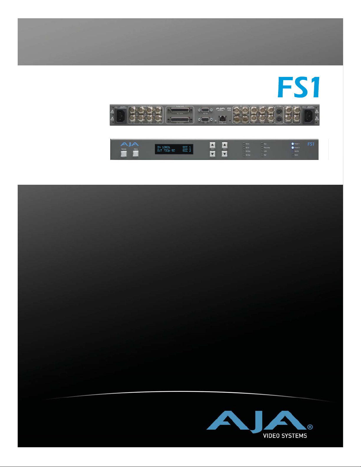
Featuring a flexible architecture, the FS1 Universal SD/HD Audio/Video Frame
Synchronizer and Converter can simultaneously work with both HD and SD
video—all in full 10-bit Broadcast quality video and 24-bit audio. The FS1 supports
virtually any input or output, analog or digital, HD or SD. The FS1 can up- or
down-convert between SD and HD, and provide simultaneous HD and SD
outputs. Cross-conversions between HD formats are also supported, with
simultaneous output of both formats. For audio, the FS1 supports 8-channel AES,
Balanced analog, or embedded audio with full flexibility. The FS1 supports closed
captioning and the conversion of closed captioning between SD and HD formats.
The FS1 is also network ready, supporting web-based remote control.
The FS1 product offers a large number of unique features for connectivity, control,
and ease of use in any environment:
•
Universal HD/SD audio/video frame synchronizer and converter
•
HD up/down conversion
SD aspect ratio conversion
•
•
HD cross conversion (720p/1080i)
•
Up/down/cross converting with both the input and converted formats on SD/
HD SDI outputs (both synchronized)
•
HD cross converting with simultaneous downconverted
SDI output
•
AFD support
•
Dual HD/SD SDI inputs and outputs
•
Component analog HD/SD input and output
1
1
1

2
Composite/S video input and output with TBC
•
8 Channel AES and balanced analog audio inputs and outputs
•
16 Channel embedded audio passed to SDI outputs
•
Audio mapping and control with AFV (audio follows video)—
•
16 channels embedded audio can be mapped to any 8
Fully redundant power supplies standard
•
10/100 LAN with SNMP, embedded web server for remote control, and
•
VTECS™ open protocol
•
Video Proc Amp
•
Closed caption support – including SD to HD upconversion
Chassis styling optimized for use in a wide variety machine rooms, with
•
simple panel and remote web browser user interfaces
Front panel alphanumeric and graphical display shows input and output
•
settings, and is also used for parameter viewing/editing
LED status indicators for at-a-glance system monitoring
•
Two GPI inputs and outputs, TTL, isolated
•
Sidebar Keyer
•
5-year international warranty, with unlimited technical support
•
FS1 Front Panel Control
FS1 operation can be monitored and changed in a number of ways:
•
Front panel control
Remote web browser via Ethernet
•
VTECS protocol via Ethernet
•
SNMP monitoring (Simple Network Management Protocol)
•
Feature sets in each of the control methods vary, although the Front Panel and
Web Browser interfaces offer much of the same features.
The front panel offers the most direct control of the device, ideally for use in
machine rooms or where quick and fast changes and status checks must
sometimes be made. Chapter 2, Controls and Indicators discusses the front and rear
panel features of the panel in great detail.
Remote Web Browser Control of FS1 via Ethernet
The FS1 internally contains an optimized web server that allows remote
monitoring and parameter setting via a network-attached computer running a
web-browser.

SNMP Interface
FS1 Installation and Operation Manual — SNMP Interface
From a network-connected computer you can communicate with one or more
FS1 devices, even getting them to identify themselves via LEDs on the front and
rear panel (front: “Identify”, rear: “ID”).
Networks can be closed local area networks or even a straight computer-to-FS1
cable, or the greatest flexibility, exposed through a firewall to a broadband
WAN.
The LAN connection on the FS1 uses a standard RJ45 connector, but internally
is intelligent and communicates via standard “straight-through” CAT 5 ethernet
cables or null-modem (cross-over) cables without any configuration or strapping
required.
Note: Firefox and Internet Explorer 7 are supported as web browsers for FS1
1
control. Other browser software may work, but AJA cannot guarantee
operation.
The browser GUI operation and features are discussed in Chapter 5.
SNMP offers remote network monitoring of alarm conditions. SNMP support
is described in Chapter 6.
3
Block Diagram
Block Diagram
Description
The FS1 features a very flexible architecture that allows simultaneous HD/SD
operation. There are actually three separate frame synchronizers in the FS1: a
full up/down/cross converting synchronizer, a downconverting synchronizer,
and a standard HD/SD non-converting synchronizer. This architecture allows
the following functions:
•
HD cross converting with simultaneous downconverted SDI output
•
Up/down/cross converting with both the input and converted formats on
SD/HD SDI outputs (both synchronized)
•
Up/down/cross converting with dual SD/HD-SDI outputs
•
Composite and S Video outputs are always active (dedicated downconverter for HD inputs)
For example, the FS1 can input 720p, and output both cross-converted 1080i
HD-SDI and down-converted 525i SDI (or the same with 1080i in and 720p
out).
The FS1 also allows the user to set the output format, and the conversion will be
automatic depending on what the input is. The FS1’s output format can also be
controlled by using the reference input (follows the reference input format).

4
Remote Web
Remote Control Panel
VTECS
SNMP
Browser
Control
GPI
Inputs
Ref
Loop
SD/HD SDI In (#1)
SD/HD SDI In (#2)
Component YPbPr In
S-Video In
Composite In
Other FS1s
Front
Panel
Control
(2)
Ref
Input
Video
Select
FS1
CPU
Genlock
Framesync
Up/Down/Cross
Converter,
Framesync,
1
ARC
Down
Converter 2,
Framesync,
1
ARC
Embedded
Web
Server
LAN or
WAN
Ethernet
Connection
Norm
Bypass
Downconvert 2
Bypass
Downconvert 2
Norm
Audio
Embed
Audio
Embed
GPI
Outputs
(2)
RS422
Port
(reserved for
future use)
SD-SDI Out or
HD-SDI Out (#1)
SD-SDI Out or
HD-SDI Out (#2)
Component YPbPr or
RGB Out
S-Video Out
Composite Out
AES/EBU Digital
Audio
Input
8-channels
Analog Audio
Input
8-channels
(Tascam-style cable)
What ’ s In The Box?
SDI 1
SDI 2
AES/EBU
Analog
Audio
Select
Audio
Processor
Notes:
ARC1 = Aspect Ratio Converter
AES/EBU digital
Audio
8-channels
Analog Audio
Output
8-channels
(Tascam-style cable)
FS1 Simplified Block Diagram
When you unpack your AJA FS1 chassis, you’ll find the following components:
•
AJA FS1 Chassis
•
AC Power cords (2).
•
The manual you’re reading (on CD).
• Optional: Late-breaking News or Read-Me-First notices (where applicable,
AJA may include additional bulletins related to your product and software).
FS1 Installation and Operation Manual — In This Manual
Please save all packaging for shipping the FS1 should you wish to do so when moving
or sending it in for service.
1
AC Power Cords (2)
5
In This Manual
FS1 Shipping Box Contents
Chapter 1 is the introduction you’re reading, listing features, box contents, and
requirements.
Chapter 2 discusses the FS1 front and rear panel connections and indicators.
Illustrations point out the various connectors and indicators with text discussions of
each.
Chapter 3 provides complete instructions for installing and configuring the FS1
panel, from unpacking, cabling the system and then getting it up and running.
Chapter 4 gets you started with setting up and using the FS1 via its front panel
controls. Discussed are the Parameter Menu and Select/Adjust buttons used to view
and edit settings.
Chapter 5 discusses controlling the FS1 remotely via a network-attached computer
with a web browser.
Chapter 6 discusses FS1 support of SNMP.
Appendix A presents a list of technical specifications for the product.
The remainder of the manual consists of an index section to help you rapidly find
topics in the manual.

6

Controls and Indicators
When installing the AJA FS1 chassis, you’ll make media cable connections to a
variety of equipment. After installation, the front panel indicators will be useful in
monitoring what is happening on the system as well as troubleshooting problems
that can occur. Becoming familiar with the FS1 front and rear panels will simplify
installation, setup, and operation of the system. Use of the Web browser user
interface and Remote Control Panel option are described in a later chapter.
On the following pages are front and rear panel illustrations with notations that
summarize all of the connectors and indicators. Detailed descriptions of each of the
connectors and indicators follow afterward.
Chapter 2:
Controls and Indicators
WARNING
Full installation instructions are provided in Chapter 3 later in this manual.
Note: The AJA FS1 should be plugged into 3-prong AC power before you make
connections to other equipment. The AC cords provide a path to ground for
accidental static discharge and protect system equipment. The FS1 has two fully
independent and redundant power supplies; it will operate with one or both AC
power cords plugged into the unit, although fault-tolerance will only exist if both
are connected.
Warning: To meet safety regulations for leakage current, connect the FS1 dual
power supplies to separate branch circuits.
1
2
1
8
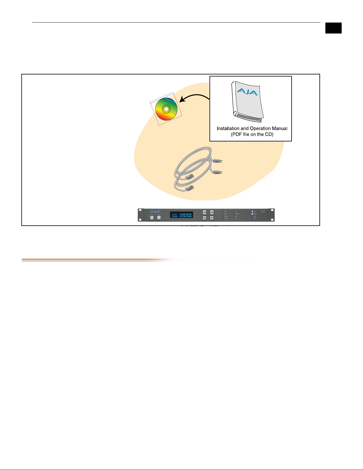
Front Panel
Control Menu
Buttons
Remote
Button
displays remote
status (color of
button) and
brings up the
remote control
menu
Status
Button
changes the
display to the
Status Mode
and cycles
through status
and screensaver
displays
Alphanumeric
Display
Alphanumeric display
has two modes:
Status (displays status
information) and
Control (for viewing and
changing functions/
parameters)
Select
a parameter
Change or
adjust value
of parameter
selected
Activity
Indicator
LEDs:
• HD In
• SD In
• HD Out
• SD Out
• Aux
• Proc Amp
• LAN
• Ref
Power and Status
Indicator
LEDs:
• Power 1
• Power 2
• Identify
• Alarm
AJA FS1 Front Panel Indicators
The Alphanumeric display has two modes:
Status: Displays current machine status and/or error conditions. The Status
display is enabled by pushing the Status button.
Control: The control mode displays the menu structure for selecting and
changing/adjusting machine functions and parameters. The display is
changed from Status to Control mode by pushing a Select or Adjust button
(the up/down arrow buttons).
When the FS1 is powered up, the display will show an AJA logo and then the
Status Display.

FS1 Installation and Operation Manual — Front Panel
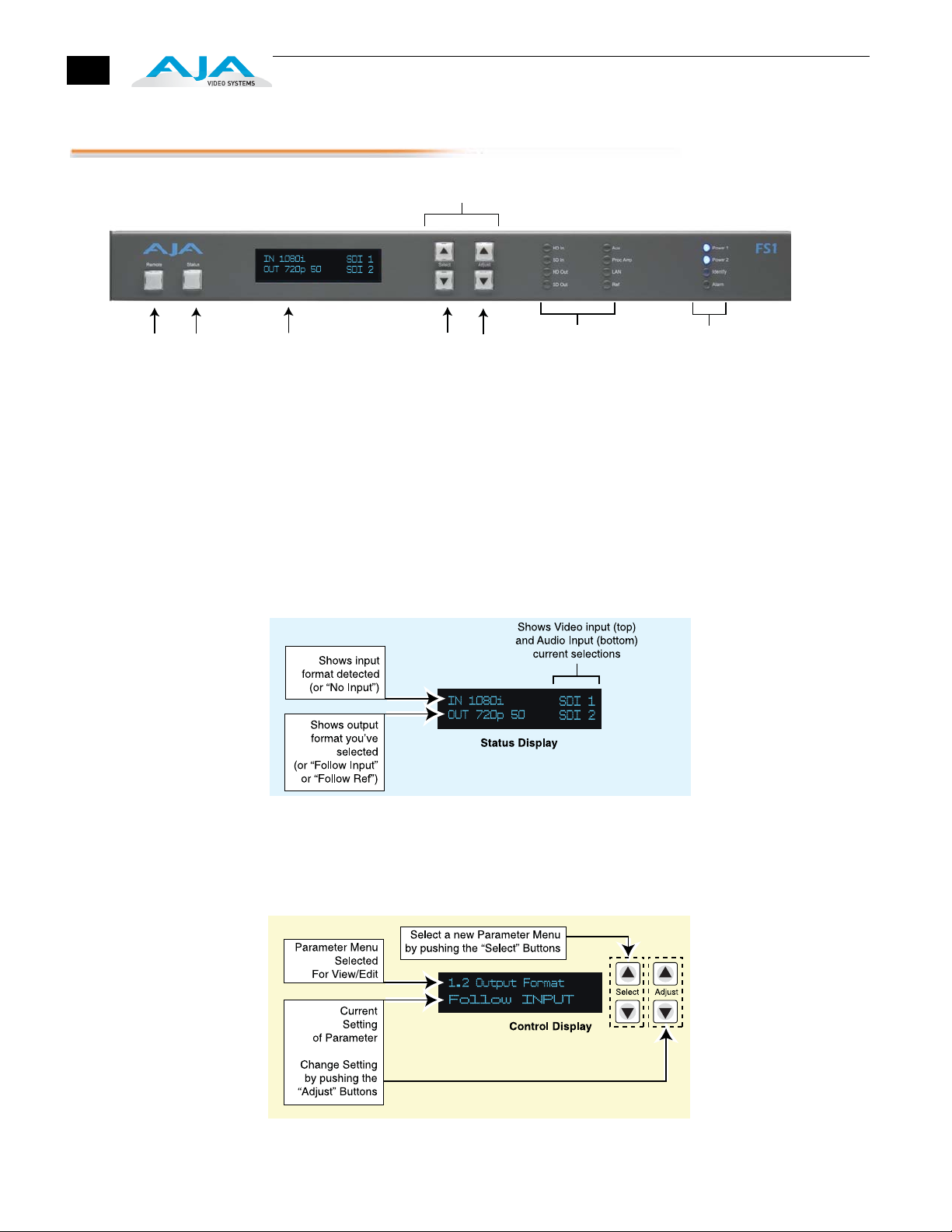
Status Display There are eight different status displays you may see (the main status display was
shown in the previous illustration). The other status displays are the video format
status display, sidebar status and sidebar input displays, power/temperature display,
close-captioning status, AJA logo, and System Name display. You can page through
the status displays by repeatedly pressing the “Status” button under the AJA logo
on the front panel.
Normally, you'll be viewing the Main Status screen shown earlier. It’s the default
screen at powerup. Information contained in the Status Display shows the
current primary settings for the FS1:
• Input Format (upper left)
9
• Output Format (lower left)
• Selected Video Input setting (upper right)
• Selected Audio Input setting (lower right)
Input Format Video Input setting
Output Format Audio Input setting
1
For example, if set up to do a cross-convert from 1080i59.94 to 720p59.94
using embedded audio in and out, the display would look as follows:
IN 1080i59.94 SDI 1
OUT 720p59.94 SDI 1
If the selected input has no valid signal present, the FS1 displays “IN No Input”.
Note: If the input is incompatible with the chosen output format, the default
status screen will display the actual format, such as “IN 525i 59.94". The video
format status screen, however, would be the 'default' status screen at that point
(since the Alarm LED would be on), and it would display “IN Incompat”.
The second status screen is the video format status screen. It shows the status of
the active video input, the output format, the genlock source, and the format of
the reference signal (if applicable). For example, if the Output Format is set to
“Follow REF”, but there is no valid reference signal present, the Output Format
section of the 'video format status' screen will read “OUT No Ref”.
The sidebar status screen shows the main input format, sidebar input format,
output format, and sidebar input select. Any incompatibilities between these
formats aare shown as “Incompat.”
The sidebar input screen always shows the detected formats of the main input
and the sidebar input—to help resolve incompatibilities.
The next status screen is the power/temperature status screen. If a power supply
error is detected, the top line of the display will read “PS 1 Error” or “PS 2
Error.” If one of the power supplies is not plugged in, or fails completely, the
display will read “PS 1 OFF” or “PS 2 OFF”, respectively. (If the Power Supply
Alarm filter (60.1) is set to “Suppress”; then it will read “Power OK” instead.)

10
If the temperature threshold is exceeded inside the FS1, the lower line of the
power/temperature status display will read “OVERHEATED”. This is an
indication that video output may be compromised. Please note, that if the Alarm
LED is lit on the front panel, the reason should be evident after examining the
video format status screen and the power/temperature status screen.
The fourth screen is a close-captioning status screen showing whether Closed
Caption data is present on the selected Video Input.
The fifth status screen is a scrolling AJA Logo. This same scrolling logo will be
displayed when no button activity has been detected for 60 minutes.
The sixth status screen is the FS1’s System Name as has been previously defined
(the System Name and how to enter/edit it is described later in Chapter 4,
Parameter Menus, System Name 50.5).
Controlling the
FS1 Using the
Select and Adjust
Buttons
The FS1's Control system is designed to be easy to operate and remember. All
functions in the menu system are numbered for easy reference. There are two sets
of up/down buttons, Select and Adjust:
Select
Adjust
To operate the FS1, one merely selects a function/parameter with the Select
buttons, and then adjusts the selected function/parameter with the Adjust
buttons.
The Control Display has two lines:
Parameter Number and Name
Current Parameter Setting
The top line contains a numbered and named FS1 parameter and or function.
The lower line contains the current setting.
The parameter Select buttons select a parameter to view or modify. Pressing one of
the parameter Adjust buttons changes the current parameter's value to a new one
from the FS1's list of choices—repeating the list if you continue to press Adjust-or
adjusting a numerical value up or down. The exact choices displayed will vary
depending on the Parameter. Adjustment choices made with the Adjust buttons
take effect immediately (except 1.1 Output Format which has a 1/2 second delay).
In most cases, changed parameters will be subsequently stored into the FS1s nonvolatile memory after it remains unchanged for 3 seconds. The exceptions to this
are the IP Address, IP Config, Subnet Mask and all SNMP parameters: for these
you must exit the selection after making changes to activate the changes.
If a Select or Adjust button is held down continuously, the changes will begin to
happen automatically - with acceleration if applicable.
Pressing either a Select or Adjust button-while on the Status or Screen Saver
displays-changes the display to the last remembered Control menu.

FS1 Installation and Operation Manual — Front Panel
Holding down both the Adjust (up) and Adjust (down) buttons—at the same time —
will set that parameter back to its factory default value.
For some parameters, once a parameter is selected the first Adjust button pressed
begins the editing. The top Select button then can be used to choose the position (left
to right) within the parameter being edited.
Holding down both the Select (up) and Select (down) buttons—at the same time —
will return the front panel menu to parameter 1.1 (Output Format). If you are editing
an octet, string or other parameter at the time that requires a commit action (like
editing an IP address that’s blinking) and you press both Select buttons, then the edit
will terminate (i.e. not take affect and not be saved). On the other hand, if you are
editing menu items that should take affect as they are edited (e.g. procamp gain), then
the edited value will directly take affect.
1
Note: Parameter displays and adjustment choices and values are described in detail
in Chapter 4.
Remote Control Pressing the Remote button once results in a display showing how the FS1 is being
controlled. Pressing the button again cycles the display through all the control options
possible:
11
Indicator
Descriptions
LOCAL+REMOTE: Control is from the panel buttons, a web browser, or remote
panel (VTECS). The Remote button will glow white.
REMOTE ONLY: Control of the FS1 is from a web browser on a network attached
computer or a remote control panel via the VTECS protocol (except for the
remote control function). The Remote button will glow red.
LOCAL ONLY: FS1 control is only allowed from the front panel buttons (except for
the remote control function). The Remote button will glow green.
Indicators on the front panel are multi-state LEDs that illuminate when a condition is
present. The following indicators are conveniently arranged in groups to show specific
subjects; each are also discussed on the following pages.
• Activity LEDs
• Power and Status LEDs
Activity Indicators
HD In—Shows that an active HD signal is detected at the previously selected input.
SD In—Shows that an active SD signal is detected at the previously selected input.
HD Out—Shows that an HD signal is being output.
SD Out—Shows that an SD signal is being output.
Aux—This LED will be ON whenever a GPI input trigger is active—if that GPI
affects the internal state of the FS1. If the associated GPI In parameter ('36.1 GPI
In 1 Response' or'36.2 GPI In 2 Response') is set to No action, then the LED will
stay OFF.

12
Proc Amp—Shows that the ProcAmp values are different from the factory nominal
values. If lit, the video passing through the FS1 is being altered according to
changes in ProcAmp parameter settings (it’s no longer at unity).
LAN—This LED will flash once whenever the FS1 is being controlled by a Web
Browser input or remote panel. Web Browser actions that do not affect the
internal state of the FS1 will not cause the LED to blink.
Ref—Shows that the FS1 has an external reference video source applied to the Ref
connector.
Power and Status Indicators
Power 1—Shows that the FS1 #1 power supply is connected to AC mains power via
its power cord and is operational. Both the Power 1 and Power 2 LEDs must be
lit to ensure redundant power is available.
Power 2—Shows that the FS1 #2 power supply is connected to AC mains power via
its power cord and is operational.
Identify and ID—These two LEDs (one on the front panel and one on the rear) will
blink when directed to do so via the FS1’s Web browser interface “Identify”
button. This action is useful for identifying which FS1 you’re controlling when
there are multiple FS1 units in a machine room being controlled by a laptop or
computer. To do so via the browser, simply click “Identify” and then watch for
one of the FS1s “Identify” LEDs to blink. The “Identify” LED on the front
panel and “ID” LED on the rear panel perform the exact same function—no
matter which side of a rack you’re facing, you’ll be able to see one of the LEDs.
Alarm—If This LED is illuminated, press the Status button to see a description of
the alarm event detected.
The Alarm LED may be lit because of a hardware failure, because of video
incompatibilities, or because of genlock loss. (Any of these conditions may be
filtered out using the Alarm Filters parameters.)
Note: only having one power cord connected to the FS1 will cause the alarm LED
to light—this may be filtered with the Alarm Filters parameters.
Video incompatibilities may be deduced from the “Alarm Status” screen. When the
Alarm LED is lit, press the front panel Status button to go directly to the “Alarm
Status” screen.
Video incompatibilities that the FS1 may detect include:
Video Incompatibility Detected Alarm Status screen will show
6.1 Genlock Source is set to “Reference”, but
Reference signal format is not compatible with
selected Output Format.
6.1 Genlock Source is set to “Reference”, and
selected Output Format is compatible with detected
Reference format, but Input signal format is not
compatible with detected Reference format.
Alarm Status screen shows:
“IN..... GEN Ref “
“OUT.... REF Incompat”
Example: if Reference and Output
formats are 525, but Input is 625,
Alarm Status screen shows:
“IN Incompat GEN Ref “
“OUT 525i 59 REF 525i 59 “

FS1 Installation and Operation Manual — Front Panel
Video Incompatibility Detected Alarm Status screen will show
13
Input signal is not compatible with selected Output
Format.
Alarm Status screen shows:
“IN Incompat “
“OUT 525i 59
Reference signal events that the FS1 may detect include:
Reference Alarm Event Alarm Status screen will show
6.1 Genlock Source is set to “Reference”, but no
Reference signal is detected.
1.1 Output Format is set to “Reference”, but no
Reference signal is detected.
Alarm Status screen shows:
“IN..... GEN Ref”
“OUT.... REF No Ref”
Alarm Status screen shows:
“IN..... GEN Ref”
“OUT.... REF No Ref”
1
Sidebar incompatibility events that the FS1 may detect include:
Sidebar incompatibility Event Alarm Status screen will show
Sidebar format incompatible with output format Alarm Status screen shows:
“IN..... SB Incompat”
“OUT.... SB ...”
About video and
format
compatibility
Main input format incompatible with Sidebar keyer Alarm Status screen shows:
“IN Incompat SB...”
“OUT.... SB...”
Sidebar Input Select incompatible with Main Input
Select (both Analog inputs)
Alarm Status screen shows:
“IN.... SB Incompat”
“OUT.... SB Incompat”
The table below shows at a glance all the conversions (and straight-through modes)
possible for given input formats. In the case of interlace formats the table lists the field
rate; for progressive formats the table lists the frame rate.
Input Possible Output Formats
525i59.94 525i59.94 720p59.94 1080i59.94
720p59.94 525i59.94 720p59.94 1080i59.94
1080i59.94 525i59.94 720p59.94 1080i59.94
1080pSF23.98 1080pSF23.981 1080i59.94 525i59.94
625i50 625i50 1080i50 720p50
720p50 625i50 1080i50 720p50
1080i50 625i50 1080i50 720p50
1080pSF24 1080pSF24 1080i60
1080i60 1080i60 720p60
720p60 720p60 1080i60
1
When the main output (SDI 1) is not 1080pSF23.98, bypass mode will not be
available.
14
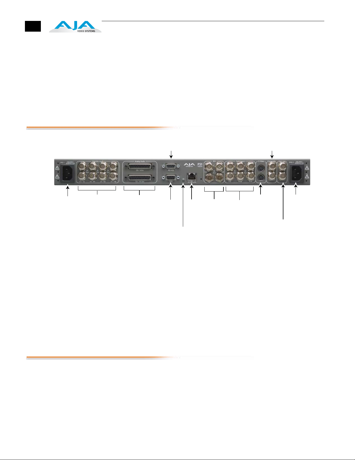
Rear Panel
Notes:
1. In the case of 1080pSF/23.98 input—and when 1080i59.94 (or 525) is
selected as an output format, the FS1 automatically adds 3:2 pulldown to get
the correct frame rate. Similarly, in the case of 1080pSF/24 input, FS1
automatically adds 3:2 pulldown to get the correct frame rate.
2. When passing 24 or 60 framerate video, the standard definition outputs will
not output valid video (the FS1 is not a framerate converter).
AC Power Supply
Socket #1
Autosensing
100 to 240VAC, 0.3A
50/60Hz
Channels 1 through 8
About Inputs and
Outputs
AES/EBU Digital
Audio In/Out
(Reserved for Future Use)
Analog Audio In/Out
Channels 1 through 8
(uses Tascam-style
cable)
RS422
DB9 Connector
GPI
9-pin
Connector
ID (Identify)
LED
10/100
RJ45
Ethernet
LAN
Connector
Serial
Digital
In/Out
(SD-SDI
HD-SDI)
Component
YPbPr and
RGB In/Out
Composite
In/Out
S-Video
In/Out
External
Reference
with LoopThrough
The function of the FS1 Inputs and Outputs depend on the operational mode.
Operation is simple in steps: first select an output format, and then select the
desired input. All outputs are active all the time. By selecting an output format first
and then the input source, the FS1 can automatically put in place any conversion
required (up/down/cross). Audio embedding/disembedding is also automatic,
following any parameter settings you’ve selected for your application. For example,
even though the input selected might be HD-SDI with embedded audio, the analog
audio output connectors will output proper analog audio that has been
disembedded from the serial digital stream.
AC Power Supply
Socket #2
Autosensing
100 to 240VAC, 0.3A
50/60Hz
Connectors
Please study Chapter 4 Parameter Menus, for a full understanding of all the FS1
settings possible.
Connectors on the rear panel are arranged in groups for easy installation and
maintenance. Connectors provided are:
• 2 AC power connectors, each 3 pin (with Ground), one for each independent
power supply. Each power supply is autosensing from 100 to 240VAC at 50/
60Hz. Only one has to be connected for FS1 operation, but redundant
operation can only be ensured if both connectors are plugged into mains
power.
• 8 channels AES/EBU digital audio in and out, two pairs per BNC.

FS1 Installation and Operation Manual — Connectors
• 8 channels of analog audio in and out via a DB25 TASCAM-style cable (not
supplied).
• GPI connector: Dual isolated TTL compatible inputs and outputs. Functions of
each are selectable in software.
• 10/100 LAN RJ45 connector.
• SDI video with embedded audio In/Out. There are two input and two output
BNC connectors. The outputs are active all the time, although you must specify
the output format (and thus whether any conversion takes place). SDI 2 can
follow the input (“bypass”)—see description on the following page.
1
• Component YPbPr/RGB Video, 3 BNCs for input, and 3 BNCs for output.
Component can follow the input (“bypass”)—see the description on the
following page.
• S-Video In/Out (Y/C), one 4-pin mini-DIN for input, and one 4-pin mini-DIN
for output—see the description on the following page.
• Composite NTSC/PAL Video In/Out, 1 BNC for input, and 1 BNC for
output—see the description on the following page.
15
Connector
Descriptions
• Reference Video (looping), 2 BNCs
• RS-422: DE-9 Reserved for future use.
Each of these groups of connectors are discussed on the following pages.
8 Channel AES/EBU Audio Inputs And
Outputs
One BNC is provided for each of four pairs of
channels, both on the input and output: 1/2, 3/4,
5/6, and 7/8.
AES/EBU signals are handled by the FS1
internally as 24-bit digital.
Analog 8 Channel Audio
The two DB25 connectors, one for input and one for
output, support a TASCAM-style cable snake for
balanced 8-channel audio. Analog audio signals are
converted internally to 24-bit digital Audio Inputs
And Outputs
RS-422 Port
This DE-9 connector is reserved for future use.
16
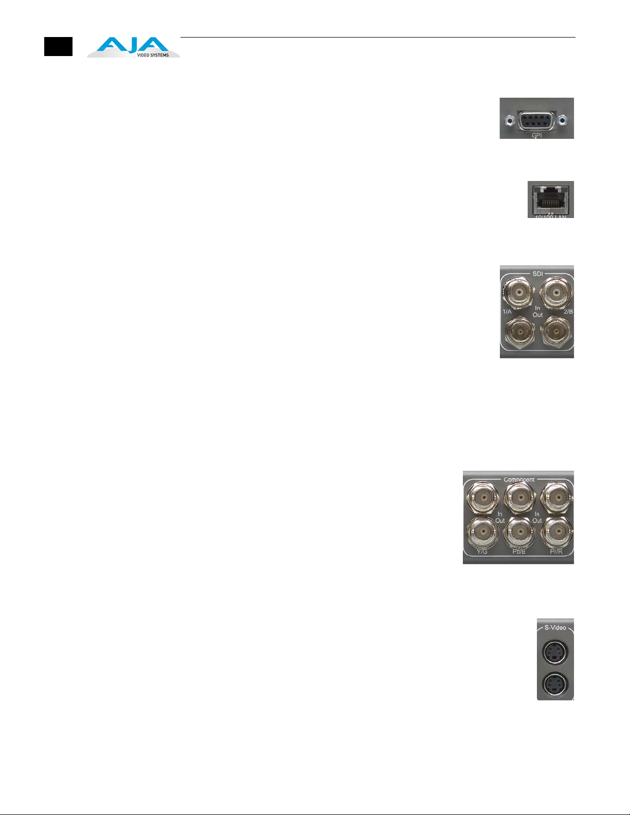
GPI
A female DE-9 connector provides connection to external
equipment or circuits via an isolated TTL-compatible interface.
Appendix B contains a pinout and specifications for the GPI
connector.
LAN
An RJ45 connector provides a 10/100 Ethernet port for connection
directly to a computer or Ethernet hub or switch for connecting to a
LAN. The FS1 is compatible with CAT-5 straight-through or cross-over
Ethernet cables, automatically detecting which is used.
SDI Input and Outputs
BNC connectors are provided for two SDI inputs and two SDI
outputs. SDI video connections include embedded audio In/Out
(depending on your parameter settings). The outputs are active all
the time, although you must specify the output format (and thus
whether any conversion takes place). For example, with an SD-SDI
input selected, you could set the SDI 1 output to HD 720p for an
upconvert, and then set the SDI 2 output to “Follow Input”
(bypass) to output the SD-SDI at the same format/framerate as the
input.
Use SDI wherever possible for the best quality 10-bit video input and output. If
peripheral equipment has a variety of inputs/outputs, look to see if it has SDI I/O,
and use it where possible.
Component (YPbPr/RGB)
Connect SD or HD component YPbPr or RGB video
cables from a VTR, camera, or other source to the three
input BNCs. Then connect the YPbPr or RGB output
BNCs to your destination component device. Component
video signals are A/D (input) and D/A (output) converted
(10-bit). Like the SDI 2 output, Component can be set to
Bypass (follow input). Output is affected by 5.3 Aspect
Ratio and 1.3 Component Out parameter settings (see
chapter 4 for discussion of these parameters).
S-Video (Y/C)
S-Video input and output female 4-pin mini-DINs provide for connection
of desktop video/prosumer level equipment, including camcorders, VCRs/
VTRs, and monitors—to name a few. Use high quality shielded S-Video
cables when making connections. S-video signals are converted internally
to 10-bit digital. Output is affected by 5.3 Aspect Ratio and 1.3 Component
Out parameter settings (see chapter 4 for discussion of these parameters).

FS1 Installation and Operation Manual — Connectors
Composite NTSC/PAL
BNC connectors support composite NTSC or PAL standard definition
input and output. Connect an NTSC or PAL composite video cable from a
VTR, Camera, or other source to the Composite In BNC. Then connect the
Composite Out BNC to a destination composite video device. Composite
video signals are A/D (input) and D/A (output) converted (10-bit). Output
is affected by 5.3 Aspect Ratio and 1.3 Component Out parameter settings (see
chapter 4 for discussion of these parameters).
Reference Video (looping)
These two BNC connectors allow you to synchronize FS1 outputs to your
house reference video signal (blackburst or composite sync for SD, or Tri-
1
level for HD). If you have a sync generator or video equipment source to use
for synchronizing other video equipment in your studio, then connect its
composite output here. When FS1 outputs video it uses this reference signal
to lock to. Reference video does not need to be the same format as the video
input/outputs, but it must have the same vertical rate (for example, 1080i
Tri-level reference video will work for 525 video input and output).
Examples of permissible reference video signals:
• 525 Color Black
• 625 Color Black
• 1080i Tri-level sync
• 720p Tri-Level sync
17

18

Installation Overview
The installation and set up of an FS1 is very simple. Plug both AC supply cords into
AC mains power, connect the LAN connector to a LAN, WAN or local computer
with a web-browser, and then connect source and destination video and audio
equipment.
WARNING
Chapter 3:
Installation & Configuration
Warning: Do not open the chassis. There are no user-serviceable parts inside.
Hazardous voltage is present inside the unit, presenting a risk of electric shock or
serious personal injury. Opening the chassis will void the warranty unless performed
by an AJA service center or licensed facility. Remove the two supplied AC line cords
from mains power when moving the unit. Do not defeat the safety purpose of the
grounding-type plug.
WARNING
Warning: To meet safety regulations for leakage current, connect the FS1 dual
power supplies to separate branch circuits.
All of the steps of Installation and Configuration are documented in this chapter,
summarized as follows:
1. Unpack the shipping box, removing the FS1 and two power cords.
2. Connect the FS1 to power, connecting the two power cords to mains AC.
3
1
1
20
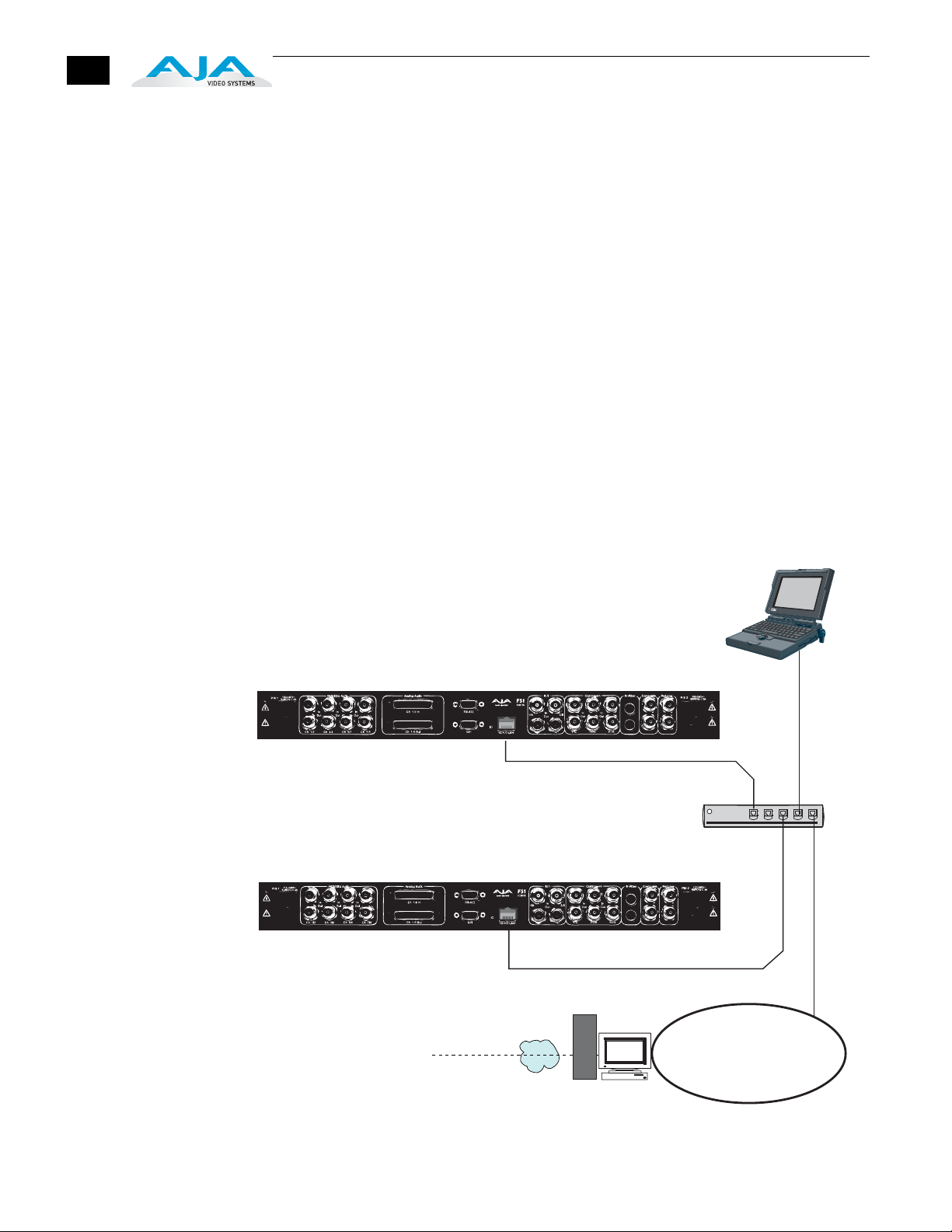
3. If remote control of the FS1 is desired, ensure you have an Ethernet cable
routed to where the FS1 will be placed. It can be connected over a LAN, or
attached directly to a locally attached computer. Ensure that the computer
(whether communicating over a LAN or directly to the FS1 Ethernet port)
has a web browser on it (FireFox or IE 7 recommended). If the FS1 will be
attached to a LAN, talk to your IT administrator and obtain the details on
how he/she wishes you to configure the FS1 (DHCP or static IP, explained
in this chapter).
4. If connecting to a network, configure the FS1 IP CONFIG, IP ADDR,
IP MASK, and IP GATEWAY parameters according to the information
obtained from your IT administrator in the last step. Connect it to the
LAN. From a network attached computer or one directly connected to the
FS1, “ping” the FS1 (explained later in this chapter).
5. Mount the physical chassis as desired: front rack, rear rack, or deskmount.
If you are mounting multiple FS1 units, try to place them visually in the
same area so if you communicate with them via a network attached
computer, you can use the FS1’s “Identify” feature to turn ON the
corresponding LED of the FS1 you’re communicating with.
6. Cable the system audio and video sources, VTR(s), monitors, and audio
equipment.
10/100Base-T
Laptop
w/Web Browser
for FS1 Remote
Control
Hub
10/100 Base-T
LAN
WAN/ISP
Firewall
& Router
FS1 Network Example, Two FS1s on a LAN, with Laptop for Remote Control
Unpacking
FS1 Installation and Operation Manual — Unpacking
21
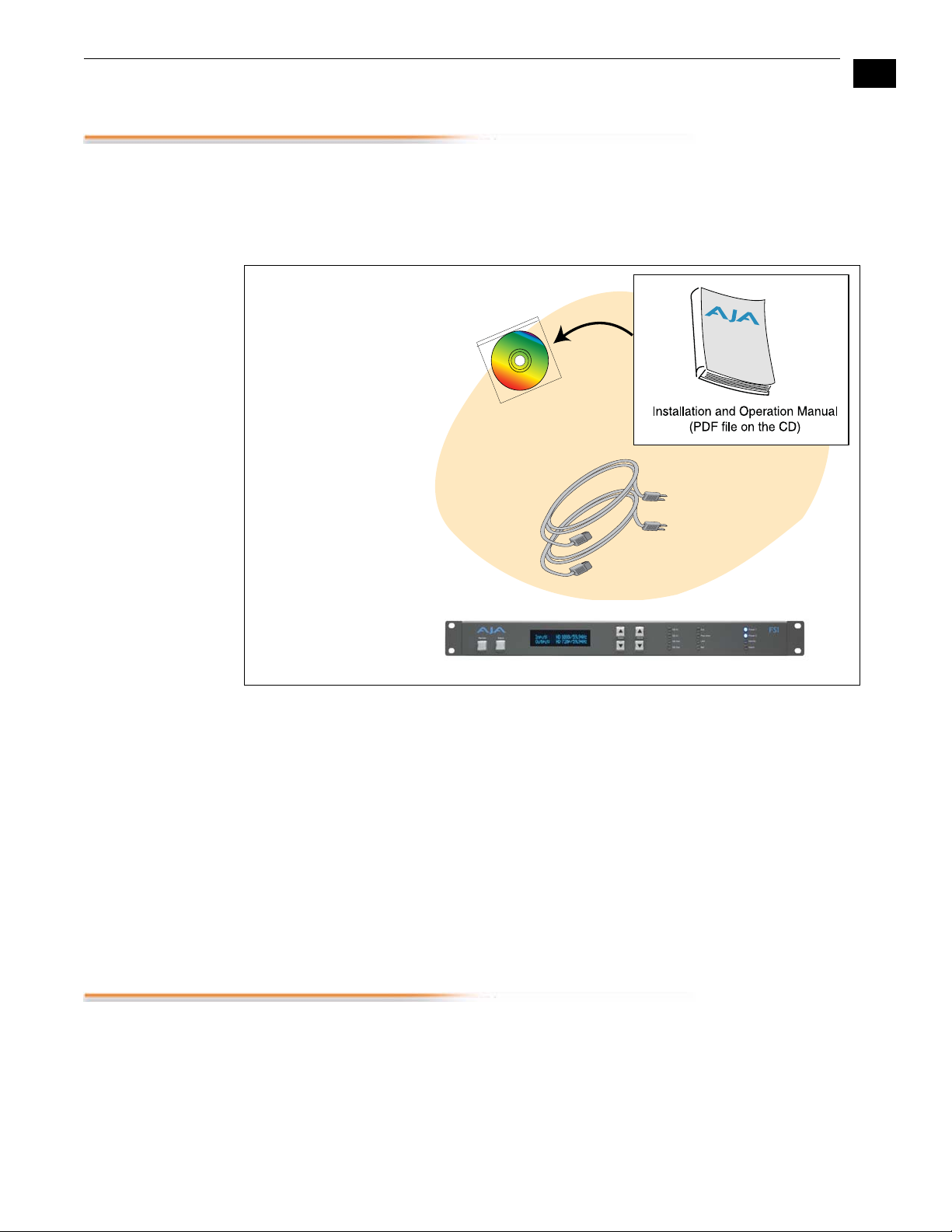
Shipping Box
Contents
An FS1 chassis is shipped with two AC power cords, a user manual CD, and any
late-breaking news bulletins (if applicable). Chassis rackmount brackets are
provided as part of the chassis with screws.
1
AC Power Cords (2)
AJA FS1 Panel Chassis
Box Contents
As you unpack the shipping box, carefully examine the contents. Ensure you
received everything and that nothing was damaged during shipment. If you find
any damage, immediately notify the shipping service and supply them with a
complete description of the damage. AJA will repair or replace damaged items.
If you find shipping damage, contact your AJA dealer or distributor for details
on how to have your FS1 repaired or replaced.
Note: Save packing materials and the shipping box. If you ever require service
or move your system—use the packaging materials and box for safe shipment.
The FS1 Chassis Rackmount or Place on a Desk
Physical
Requirements
You can locate your chassis in two ways:
• Rackmounting—attach the FS1 (rear or front mounted) to a standard 19”
equipment rack. The FS1 chassis takes up only one rack unit vertically.
• Desktop—lay it on a horizontal flat surface.

22
When planning equipment locations and mounting methods, take into account
the size of the chassis:
Network Connection
The FS1 can be networked directly to a laptop or other desktop computer using a
single Ethernet cable (straight or cross-over)—or it can be connected to a local
area network (LAN). In either case, the FS1 connects via its 10/100Base-TX
Ethernet connector. A LAN is a shared network that includes other Ethernet
devices all attached via a hub or digital switch. LANs may be divided into zones
separated by software or hardware routers. Routers may also be used to connect
the LAN to an outside wide area network (WAN) such as the internet. Devices on
a LAN have IP addresses which may be fixed and permanent, or dynamically
assigned by the network (DHCP). When attaching the FS1 to a LAN, you should
first talk to your network administrator and find out how they want it connected
(static IP or DHCP). Your IT department will be able to supply the information
you need to install the FS1 on a LAN.
• Chassis Dimensions:
Height—1 rack units, 1.75” (4.445 cm)
Depth—12” (30.48 cm)
Width—17.25” (43.8 cm)
TCP/IP Information
You’ll Need
Networking the
FS1 via DHCP
If your LAN has a DHCP server that assigns IP addresses dynamically, then you
don’t have to configure anything (the FS1 defaults to DHCP). If for some reason
your IT administrator prefers an assigned IP address that is fixed (called a “static
IP), then get the IP address—you’ll be entering it in the “IP CONFIG parameter”
of the FS1. If your LAN requires static IP addresses, then also ask your IT
administrator for the Subnet Mask and default gateway IP address (your LAN’s
internet router). The following two topics discuss two different ways to set up the
FS1: via DHCP or via a static IP address.
The FS1 default configuration (from the factory) automatically looks for a DHCP
server to issue an IP address. So, as long as your network has a DHCP server
(usually part of your router), then you need to do nothing other than plugging the
FS1 into the net. To manually select DHCP: use the Select buttons to navigate to
the parameter “50.1 IP CONFIG”, and then use the Adjust buttons to select
“DHCP”. That’s it!
 Loading...