

Aiwa TV-FA2500 Service Manual
TV-FA2500
SH, SHA
SERVICE MANUAL
COLOR TELEVISION
• This Service Manual is the “Revision Publishing” and replaces “Simple Manual”
of TV-FA2500 <SH>, (S/M Code No. 09-009-437-6T1) and TV-FA2500 <SHA>,
(S/M Code No. 09-009-437-6T2).
S/M Code No. 09-00A-437-6R1
REVISION
DATA

TABLE OF CONTENT
SPECIFICATIONS ................................................................................................................................................................3
ACCESSORIES / PACKAGE LIST ...................................................................................................................................... 3
NOTICES BEFORE REPAIRING........................................................................................................................................ 4
DISASSEMBLY INSTRUCTIONS.................................................................................................................................. 5 ~ 9
ELECTRICAL MAIN PARTS LIST ........................................................................................................................... 10 ~ 13
TRANSISTOR ILLUSTRATION ......................................................................................................................................... 14
WIRING – 1 (MAIN) ........................................................................................................................................................... 15
SCHEMATIC DIAGRAM – 1 (MAIN)................................................................................................................................. 16
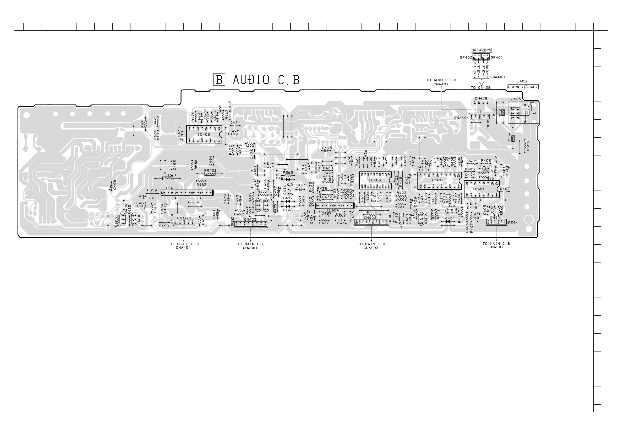
WIRING – 2 (AUDIO : SH) ................................................................................................................................................. 17
WIRING – 3 (AUDIO : SHA)............................................................................................................................................... 18
SCHEMATIC DIAGRAM – 2 (AUDIO : SH, SHA) ............................................................................................................. 19
WIRING – 4 (NK : SH) ....................................................................................................................................................... 20
WIRING – 5 (NK : SHA) ..................................................................................................................................................... 21
SCHEMATIC DIAGRAM – 3 (NK : SH, SHA) ................................................................................................................... 22
WIRING – 6 (PIN : SH) ...................................................................................................................................................... 23
WIRING – 7 (PIN : SHA) .................................................................................................................................................... 24
SCHEMATIC DIAGRAM – 4 (PIN : SH, SHA) .................................................................................................................. 25
IC BLOCK DIAGRAM.................................................................................................................................................26 ~ 27
IC DESCRIPTION ......................................................................................................................................................28 ~ 31
WAVEFORM ...............................................................................................................................................................32 ~ 38
VOLTAGE CHART..................................................................................................................................................... 39 ~ 43
ADJUSTMENT ............................................................................................................................................................44 ~ 58
MECHANICAL EXPLODED VIEW 1 / 1........................................................................................................................... 59
MECHANICAL PARTS LIST 1 / 1 .................................................................................................................................... 60
– 2 –

SPECIFICATIONS
Tuner System Frequency synthesized tuner
TV System PAL (B/G, H, I, D/K)
Channel Coverage VHF: E2 to E12, R1 to R12
Program Memory 100 TV stations
Antenna Input 75 ohms, unbalanced
Picture Tube 25"
Screen Size 478 (W) X 359 (H) mm (187/8 X 141/4 in.)
Video Input /Output 1 Vp-p 75 ohms
Audio Input -8 dBs., more than 33 k ohms
Audio Output -8 dBs., less than 2.2 k ohms
Speaker 60 X 120 mm (23/8 X 43/4 in.)
Operating Voltage 110 - 240 V AC, 50/60 Hz
Power Consumption 125 W (Standby mode: 13 W)
Phones Jack Stereo-mini jack
Operating Temperature 5 °C – 40 °C
Operating Humidity 35 % – 80 %
Dimensions 690 (W) X 506 (H) X 485 (D) mm
Weight 32.5 kg (71.5 lbs.)
• Design and specifications are subject to change without
notice.
SECAM (B/G, I, D/K, K1)
NTSC(M)
UHF: 21 to 69
CATV: S1 to S41
598 mm (diagonal) (235/8 in.)
10 W + 10 W (10 % Harmonic distortion)
(271/4 x 20 x 19 1/8 in.)
ACCESSORIES / PACKAGE LIST
REF. NO. DESCRIPTIONPART NO.
1 8A-JEK-902-010 IB,SH (ECAPR) FA2100/2500-M
2 8A-JEA-951-010 RC UNIT,RC-ZVT25
KANRI
NO.
– 3 –
NOTICES BEFORE REPAIRING
To make the best use of this equipment, make sure to
obey the following items when repairing (or mending).
1. Do not damage or melt the tunicate of the leading
wire on the AC1 side, including the power supply
cord.
2. Do not soil or stain the letters on the spec.
inscription plates, notice labels, fuse labels, etc.
3. When repairing the part extracted from the
conducted side of the board pattern, fix it firmly
with applying bond to the pattern and the part.
4. Restore the following items after repairing.
1) Conditions of soldering of the wires (especially,
the distance on the AC1 side).
2) Conditions of wiring, bundling of wires, etc.
3) Types of the wries.
4) Attachment conditions of all types of the insulation.
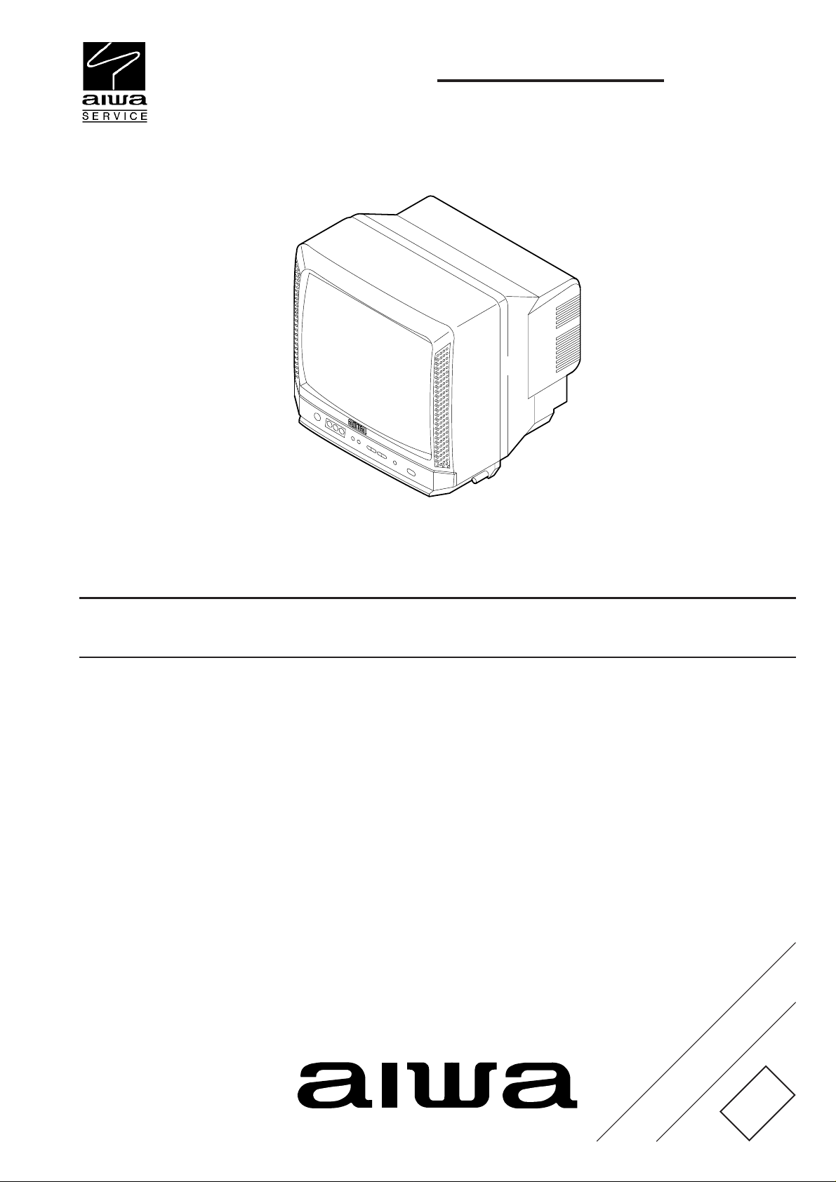
5. After repairing, always measure the insulation
resistance and perform the voltage-withstand test
(See Fig-1).
1) The insulation resistance must be 6 MΩ to 10 MΩ
when applying
2) In the voltage withstand test, apply 3 kV for 1 min
and check that the GO lamp lights.
500V per second.
Insulation resistance: 6 MΩ to 10 MΩ (500 V/s)
Voltage-withstand: 3 kV for 1 min
Safety checker (Model 7110, etc.)
Earth cable
AC cable
Connect the earth cable
to the outside metal part
terminal.
Fig-1
* Breaking current set to 10 mA.
* Connect the safety checker as shown in Fig-1,
then measure the resistance and perform the test.
* Do not touch the equipment during testing.
* For details of the safety checker, refer to the supplied
Operation manual.
When servicing and checking on the TV, note the followings.
1. Keep the notices.
As for the places which need special attentions, they
are indicated with labels or seals on the cabinet,
chassis and parts. Make sure to keep the indications
and notices in the operation manual.
2. Avoid an electric shock.
There is a high voltage part inside. Avoid an electric
shock while the electric current is flowing.
3. Use the designated parts.
The parts in this equipment have the specific
characteristics of incombustibility and withstand voltage
for safety.
Therefore, use a part which has the same character
as the replaced part. Especially as to the important
parts for safety which is indicated in the circuit
diagram or the table of parts with a mark, the
designated parts must be used.
4. Put parts and wires in the original position after
assembling or wiring.
There are parts which use the insulation material such
as a tube or tape for safety, or which are assembled so
that these parts do not make contact with the printed
!
board. The inside wiring is designed not to get close to
the pyrogenic parts and high voltage parts. Therefore,
put these parts in the original positions.
5. Take care of the cathode-ray tube.
By setting an explosion-proof cathode-ray tube in this
equipment, safety is secured against implosion.
However, when removing it or servicing from the
back, it gives out shock that is dangerous. Take
enough care to deal with it.
6. Avoid an X-ray.
Safety is secured against an X-ray by giving
considerations to the cathode-ray tube and the high
voltage peripheral circuit, etc. Therefore, when
repairing the high voltage peripheral circuit, use the
designated parts and do not change the circuit.
Repairing, except indicates, causes rising of high
voltage, and the cathode-ray tube emits an X-ray.
7. Perform a safety check after servicing.
Confirm that the screws, parts and wiring which were
removed in order to service are put in the original
positions, or whether there are deteriorated portions
around the places serviced.
!
Safety Components Symbol
This symbol is given to important parts which serve to maintain the safety of the product, and which
are made to confirm to special Safety Specifications.
Therefore, when replacing a component with this symbol make absolutely sure that you use a
designated part.
– 4 –
Anode cap
CRT GND
Hook
CRT
CRT GND
Grip
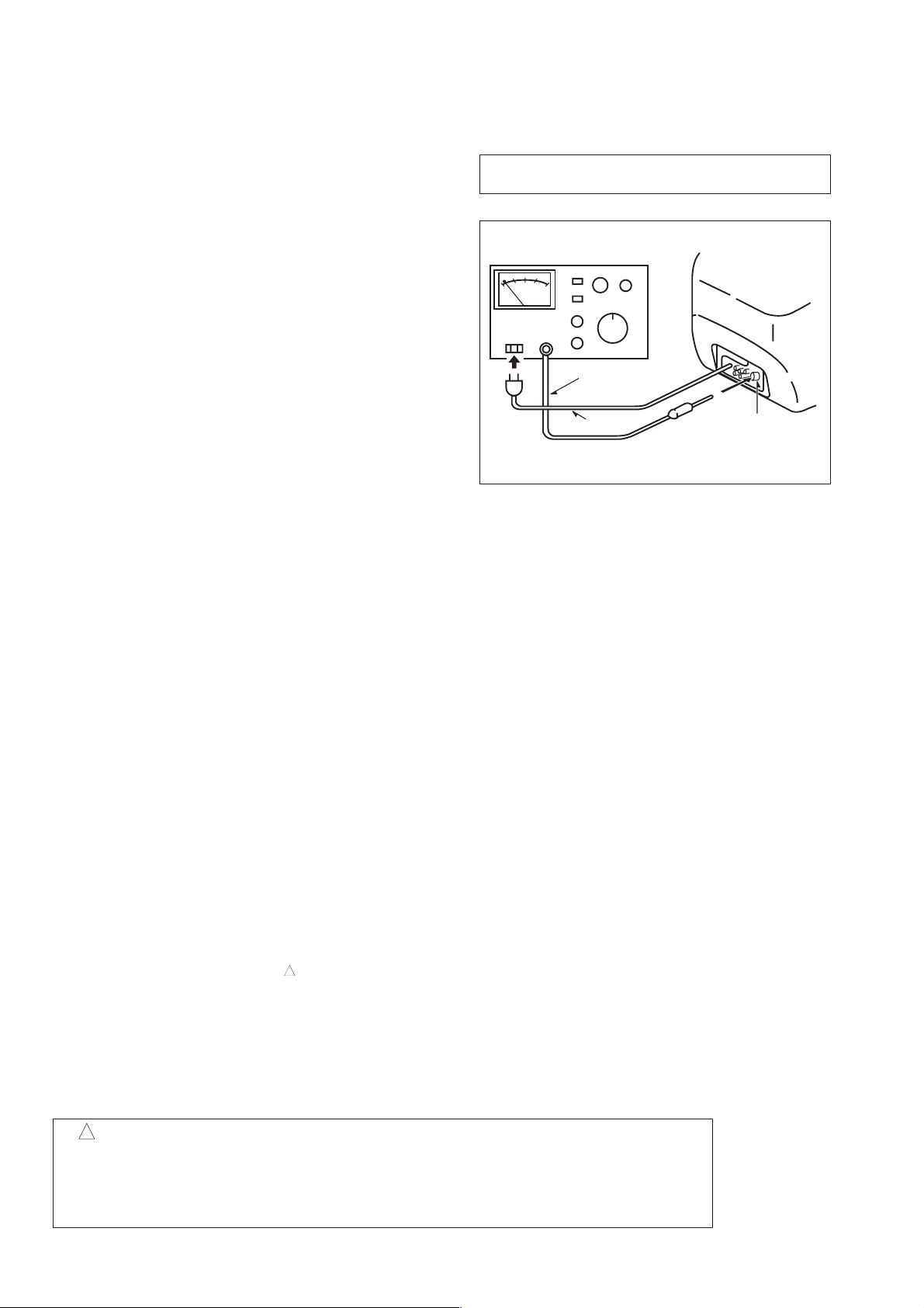
DISASSEMBLY INSTRUCTIONS
1. REAR CABINET REMOVAL
(1) Remove eight screws 1, then remove the rear cabinet in
the direction of the arrow.
(See Figure1-1)
2. HIGH-VOLTAGE CAP (ANODE CAP) REMOVAL
Front cabinet
Rear cabinet
Figure 1-1
2-1. Cautions before Removing
Discharge the anode voltage
(1) The anode voltage is not discharged completely from the
CRT of this unit even after the power is turned off. Be
sure to discharge the residual anode voltage before
removing the anode cap.
Do not use pliers
(2) Do not use pliers, etc. to remove the anode cap. If you
used pliers and bent the hook to remove the cap, the spring
characteristics of the hook could be lost, and when
reinstalled, the cap would come off from the CRT anode
button easily, causing an accident.
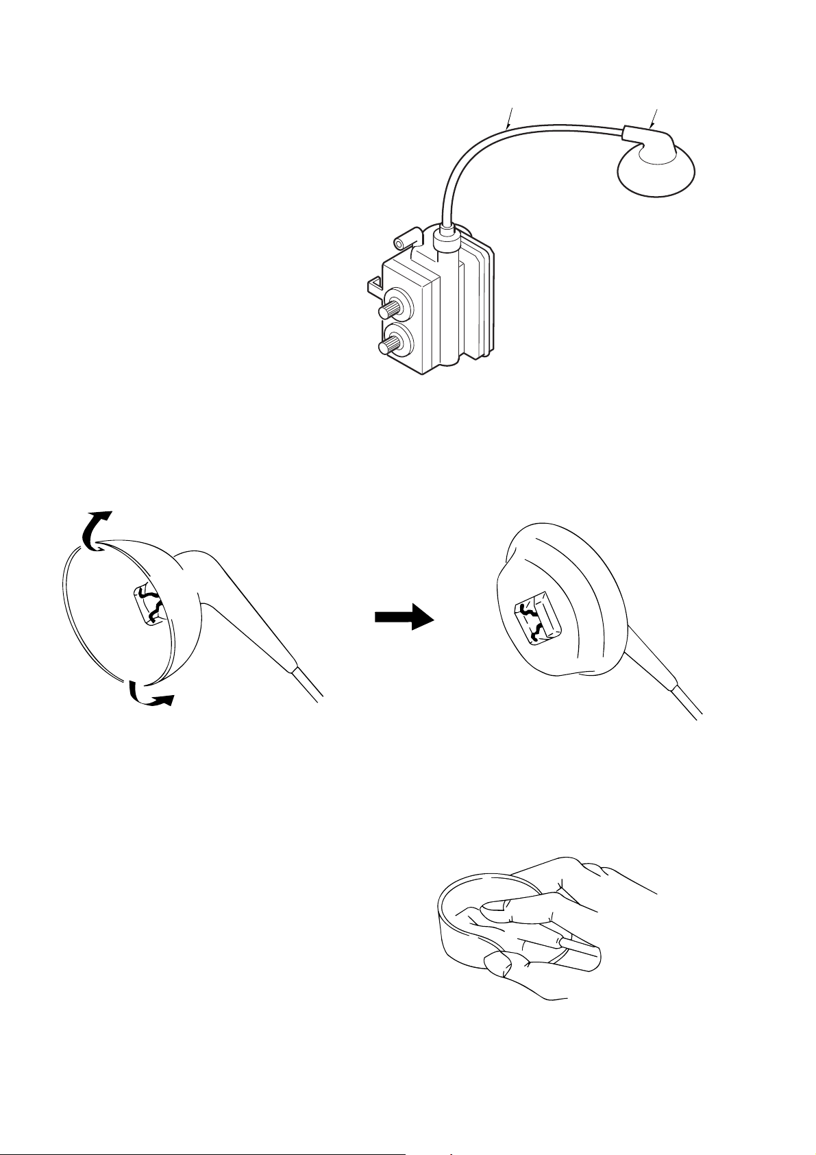
Do not turn the anode cap
(3) If the anode cap is turned in the direction of its
circumference, the hook is likely to come off.
Figure 2-1
2-2. Anode Cap Removal
Discharge the anode voltage. (See Figure 2-1)
(1) Connect a flat-bladed screwdriver to the CRT GND via
an alligator clip.
(2) Use a tester to check the end of the screwdriver and ground
of the TV for continuity.
(3) Touch the hook with the end of the screwdriver.
Caution : Be careful not to damage the anode cap.
(4) Turn over the anode cap.
Caution : Be careful not to damage the anode cap.
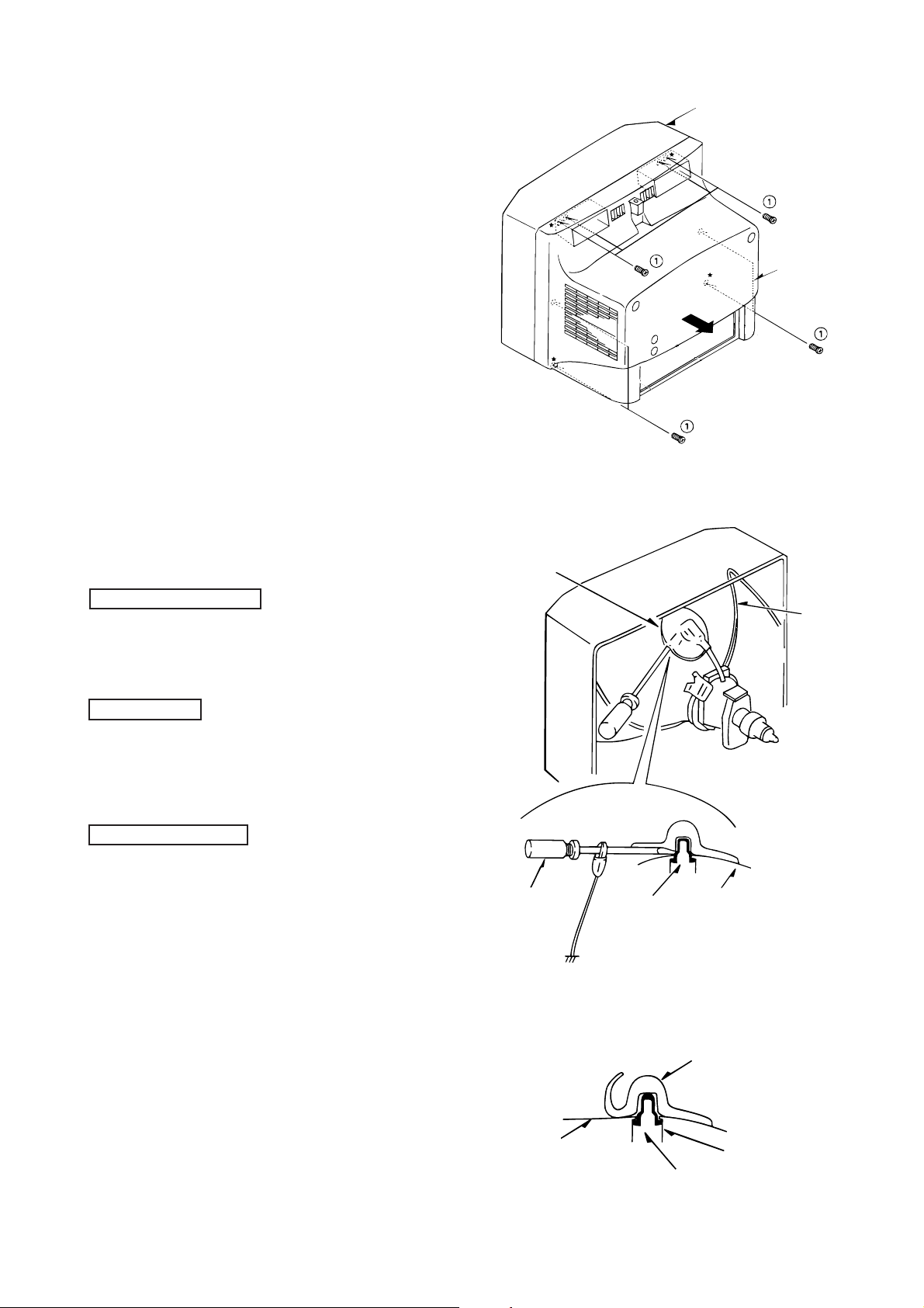
– 5 –
CRT
Anode cap
Anode button
Hook
Figure 2-2
(5) Push the anode cap with your thumb in the direction of
arrow 1 as shown in the figure, then lift the cap in the
direction of arrow 2 to release the hook on one side.
(See Figure 2-3)
Anode cap
(6) Turn over the anode cap on the side where the hook was
released and pull out the cap in the direction opposite to
that on which the cap was pushed. (See Figure 2-4)
Caution : Do not pull out the anode cap straight up.
: Do not pull the cap forcibly. After removing
the cap, check that the hook is not deformed.
3. ANODE CAP REINSTALLATION
Observe the cautions carefully so that no accident occurs
due to a defect in installing the anode cap and so it does
not come off.
CRT
Hook
Left
CRT
Hook
Figure 2-3
Anode cap
CRT
Anode button
Hook
Figure 2-4
Anode cap
Right
3-1. Caution before Reinstalling
Never turn the anode cap after installing it
Never re-use the hook when it has been deformed
(1) If the anode cap is turned after it is installed, it may come
off. Therefore, arrange the high-voltage cable before
attaching the anode cap. (See Figure 3-1)
(2) If you have attached the anode cap before arranging the
high-voltage cable, arrange the cable carefully so the cap
does not turn.
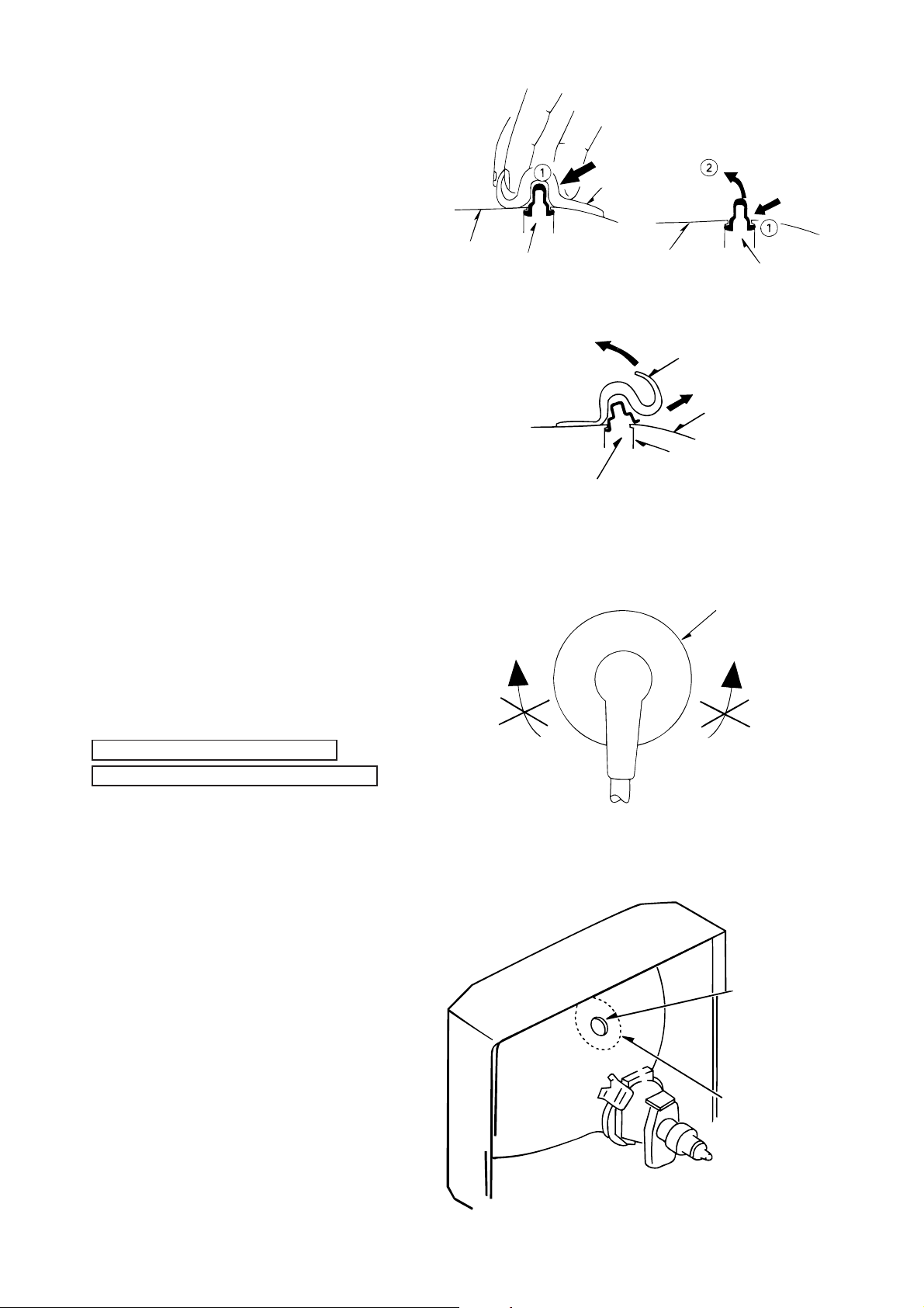
3-2. Anode cap reinstallation
(1) Use a clean cloth moistened slightly with alcohol to clean
the installation section. (See Figure 3-2)
Caution : Check that the installation section is free from
dust, foreign matter, etc.
(2) Coat the anode cap installation circumference with an
appropriate amount of the specified silicone grease (KS650N).
Caution : Be careful that silicone grease does not enter
the anode button.
Figure 3-1
Anode button
Installation
section
– 6 –
Figure 3-2
(3) Eliminate twisting, etc. of the high-voltage cable and
arrange it so that no twisting occurs. (See Figure 3-3)
Caution : If the cable is not arranged correctly , the anode
cap could turn and cause an installation defect.
(4) Turn over the rubber cap symmetrically on the left and
right. (See Figure 3-4)
Caution : Take great care not to damage the anode cap.
High-voltage cable
Anode cap
Figure 3-3
(5) Fit your forefinger over the projection at the center of the
cap and hold the cap between your thumb and middle
finger. (See Figure 3-5)
Figure 3-4
Figure 3-5
– 7 –
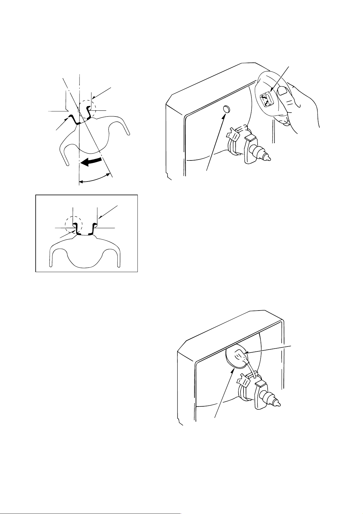
(6) Apply the hook on one side to the anode button as shown
Hook
Anode button
on the figure. (See Figure 3-6)
Caution : Check that the hook is held securely.
(7) Apply the hook on the other side to the anode button as
shown in Figure 3-7.
Anode button
Hook
30°
Anode button
Hook
Figure 3-7
(8) Pull the anode cap slightly with the rubber cap turned
over and visually check that the hook is engaged securely.
(9) Release your hand from the rubber cap of the anode cap.
Caution : Cover the anode cap so that it does not lift.
(10) Hold the skirt of the andoe cap slightly to improve the
close contact between the cap and CRT.
(11) Check that the anode cap is in close contact with the CRT .
(See Figure 3-8)
Figure 3-6
Anode button
Skirt
Figure 3-8
– 8 –
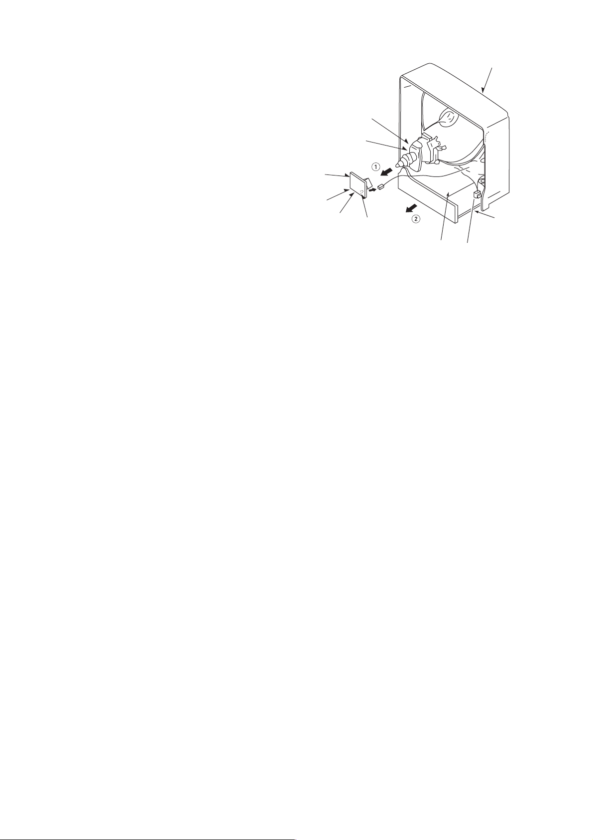
4. NK C.B. (PWB, NK) REMOVAL
(1) Disconnect CN903 (CRT GND).
(2) Disconnect CN901, CN902
(3) Remove the NK C.B. in the direction of arrow 1.
(See Figure 4-1)
5. MAIN C.B (PWB, MAIN) REMOVAL
(1) Remove connector (CN408).
(2) Remove connector (CN801).
(3) Remove connector (CN802).
(4) Pull out the MAIN C.B. in the direction of the arrow 2
(See Figure 4-1).
CN801
(Power Cord)
CN802
(Degauss
cord)
NK C.B
CN901
CN902
CN903
Front cabinet
AUDIO C.B
MAIN C.B
CN408
(Speakers)
Figure 4-1
– 9 –

ELECTRICAL MAIN PARTS LIST
REF. NO. DESCRIPTIONPART NO.
NO.
IC
87-A21-433-010 IC,KS24C041I
87-017-804--010 IC,BU4052BC
87-A21-723-010 IC,TB1240AN AJE-H
87-A21-166-010 IC,TA1275AZ
87-A21-259-010 IC,MM1454XD
87-A21-345-010 IC,NJM2150
87-A20-312-010 IC,M62420SP
87-A21-299-010 IC,LA6458SLL
87-A21-169-010 IC,MM1124B
87-A21-283-010 IC,AN5277
87-A21-456-010 IC,LA7833
87-070-417-010 IC,NJM4558 DD
87-A21-344-010 IC,STR-F6656
87-A21-787-010 IC,KIA7805API
87-A21-788-010 IC,KIA7809API
8A-JEE-652-010 IC,TMP87CP38N-1N15 THAI<SH>
8A-JEE-651-010 IC,TMP87CP38N-1N14<SHA>
87-A21-133-080 IC,BMR-0101D
87-A91-538-010 RCR UNIT,SBX1981-72P
87-A21-457-010 IC,SE120N
TRANSISTOR
87-A30-090-080 FET,2SK2541
87-A30-091-080 FET,2SJ460
89-337-794-580 TR,2SC3779 D/E
87-A30-066-080 TR,2SA1175FE
87-A30-065-080 TR,2SC2785FE
89-109-504-080 TR,2SA950
87-026-218-080 TR,DTC144ES (0.2W)
87-A30-121-080 TR,DTC 323 TS
87-A30-366-010 TR,2SD2580
89-334-674-580 TR,2SC3467 D/E
87-A30-363-010 TR,2SD2531
89-110-155-080 TR,2SA1015GR
87-A30-344-010 TR,2SC5147D
89-347-930-010 TR,2SC4793
89-118-370-010 TR,2SA1837
87-026-462-080 TR,2SC1740SRS
87-026-463-080 TR,2SA933SRS
89-407-742-080 TR,2SD774
DIODE
87-070-345-080 DIODE,IN4148
87-A40-347-080 ZENER,MTZJ2.2B
87-070-444-080 ZENER,HZS33-1TA
87-A40-235-080 ZENER,MTZJ9.1C
87-A40-350-080 ZENER,MTZJ 4.7C
87-070-092-080 DIODE,S5566B
87-A40-286-080 DIODE,RGP10JE-5025
87-A40-794-080 DIODE,EGP20G
87-A40-735-090 DIODE,ERC06-15
87-017-593-090 DIODE,RGP15J
87-017-654-060 DIODE,GBU6J
87-A40-509-080 ZENER,MTZJ6.8C
87-A40-450-090 DIODE,RU 1P
87-A40-850-090 DIODE,RL4A
87-A40-354-090 DIODE,UF3GL-6251
87-A40-611-080 ZENER,MTZJ3.9B
87-A40-736-080 DIODE,IN4148(SEM)
87-017-650-080 DIODE,1SS119
87-A40-503-080 ZENER,MTZJ39B
87-A40-574-080 ZENER,MTZJ3.0A
MAIN C.B
C1 87-A11-073-080 CAP, TC U 22P-50 J CH
C2 87-A11-073-080 CAP, TC U 22P-50 J CH
REF. NO. DESCRIPTIONPART NO.KANRI
C3 87-010-405-080 CAP, ELECT 10-50V
C4 87-018-134-080 CAPACITOR,TC-U 0.01-16
C5 87-010-263-080 CAP, ELECT 100-10V
C6 87-018-119-080 CAP, CER 100P-50V
C7 87-010-405-080 CAP, ELECT 10-50V
C8 87-010-405-080 CAP, ELECT 10-50V
C9 87-018-134-080 CAPACITOR,TC-U 0.01-16
C10 87-018-119-080 CAP, CER 100P-50V
C11 87-018-119-080 CAP, CER 100P-50V
C13 87-010-405-080 CAP, ELECT 10-50V
C14 87-018-129-080 CAP, CER 680P-50V
C15 87-018-149-080 CAP, TC-U 15P-50 CH
C16 87-018-149-080 CAP, TC-U 15P-50 CH
C17 87-010-404-080 CAP, ELECT 4.7-50V
C101 87-010-404-080 CAP, ELECT 4.7-50V
C102 87-018-134-080 CAPACITOR,TC-U 0.01-16
C103 87-010-384-080 CAP, ELECT 100-25V
C104 87-018-134-080 CAPACITOR,TC-U 0.01-16
C105 87-010-263-080 CAP, ELECT 100-10V
C106 87-A11-132-080 CAP, TC U 0.01-50 K B UP050
C107 87-018-134-080 CAPACITOR,TC-U 0.01-16
C108 87-018-132-080 CAP, CER 2200P-16V
C110 87-018-132-080 CAP, CER 2200P-16V
C113 87-010-260-080 CAP, ELECT 47-25V
C114 87-018-113-080 CAP, TC U 33P-50 J SL UP050
C115 87-018-119-080 CAP, TC U 100P-50 K B UP050
C116 87-010-260-080 CAP, ELECT 47-25V
C117 87-018-134-080 CAPACITOR,TC-U 0.01-16
C120 87-010-405-080 CAP, ELECT 10-50M 11L SME
C121 87-018-134-080 CAPACITOR,TC-U 0.01-16
C122 87-010-260-080 CAP, ELECT 47-25V
C124 87-010-401-080 CAP, ELECT 1-50V
C125 87-018-134-080 CAPACITOR,TC-U 0.01-16
C126 87-010-544-080 CAP, ELECT 0.1-50V
C127 87-018-119-080 CAP, CER 100P-50V
C128 87-018-134-080 CAPACITOR,TC-U 0.01-16
C129 87-018-134-080 CAPACITOR,TC-U 0.01-16
C130 87-010-405-080 CAP, ELECT 10-50V
C131 87-010-405-080 CAP, ELECT 10-50V
C132 87-010-260-080 CAP, ELECT 47-25V
C134 87-018-134-080 CAP, TC U 0.01-16 N Y UP050
C152 87-010-384-080 CAP, ELECT 100-25V
C301 87-010-545-080 CAP, ELECT 0.22-50V
C302 87-018-132-080 CAP, CER 2200P-16V
C303 87-018-148-080 CAP, TC-U 12P-50 CH
C307 87-018-134-080 CAPACITOR,TC-U 0.01-16
C308 87-010-385-080 CAP, E 220-25 M SME
C309 87-018-147-080 CAP, TC-U 10P-50 CH
C310 87-018-147-080 CAP, TC-U 10P-50 CH
C311 87-018-147-080 CAP, TC-U 10P-50 CH
C312 87-010-404-080 CAP, ELECT 4.7-50V
C313 87-018-119-080 CAP, CER 100P-50V
C315 87-018-196-080 CAP, CER 1500P-16V
C316 87-010-400-080 CAP, ELECT 0.47-50V
C317 87-010-237-080 CAP, ELECT 1000-16 M SME
C318 87-018-134-080 CAPACITOR,TC-U 0.01-16
C319 87-010-400-080 CAP, ELECT 0.47-50V
C320 87-010-384-080 CAP, ELECT 100-25V
C321 87-018-134-080 CAPACITOR,TC-U 0.01-16
C323 87-A11-148-080 CAP, TC U 0.1-50 Z F
C324 87-A11-148-080 CAP, TC U 0.1-50 Z F
C328 87-010-400-080 CAP, ELECT 0.47-50V
C330 87-018-134-080 CAPACITOR,TC-U 0.01-16
C333 87-018-134-080 CAPACITOR,TC-U 0.01-16
C334 87-010-263-080 CAP, ELECT 100-10V
C335 87-010-401-080 CAP, ELECT 1-50V
C336 87-018-134-080 CAPACITOR,TC-U 0.01-16
C337 87-010-401-080 CAP, ELECT 1-50V
C338 87-010-401-080 CAP, ELECT 1-50V
C339 87-010-263-080 CAP, ELECT 100-10V
KANRI
NO.
– 10 –

REF. NO. DESCRIPTIONPART NO.
NO.
C340 87-018-134-080 CAPACITOR,TC-U 0.01-16
C341 87-018-134-080 CAPACITOR,TC-U 0.01-16
C344 87-010-263-080 CAP, ELECT 100-10V
C501 87-018-126-080 CAP,TC-U 390P-50 B
C503 87-010-247-080 CAP, ELECT 100-50V
C508 87-010-402-080 CAP, ELECT 2.2-50V
C511 87-A11-245-080 CAP,M/P 0.1-100 J TF-ECQV
C512 87-A10-011-090 CAP,E 2200-25 SMG
C513 87-018-127-080 CAP, CER 470P-50V
C601 87-A10-406-010 CAP,CER 270P-2K K BN DE
C603 87-A10-052-080 CAP,E 2.2-250
C606 87-016-515-080 CAP,CER 1000P-1K B
C607 87-010-397-090 CAP,E 1000-35 SME
C609 87-010-386-080 CAP,E330-25 SME
C616 87-018-132-080 CAP, CER 2200P-16V
C617 87-010-976-080 CAP,CER 1000P-500 B
C618 87-010-974-080 CAP,CER 220P-500 B
C619 87-016-215-080 CAP,E 1-160 M TWSS
C801 87-A10-688-090 CAP,M/P 0.22-275 K (B81133)
!
C802 87-A10-688-090 CAP,M/P 0.22-275 K (B81133)
!
!
C805 87-A10-517-010 CAP,CER 3300P-4K M E KX
C807 87-A10-646-090 CAP,E 220-400 SMH (25.4*40)
C808 87-A11-825-080 CAP,CER 120P-2K J SL
C809 87-018-131-080 CAP, CER 1000P-50V
C810 87-010-384-080 CAP, ELECT 100-25V
C811 87-018-127-080 CAP, CER 470P-50V
C812 87-018-129-080 CAP, CER 680P-50V
C813 87-A10-626-090 CAP,M/P 0.01-1250 J
C814 87-A11-779-090 CAP,M/P 1000P-1.6K J ECWH(VB)
C815 87-A11-779-090 CAP,M/P 1000P-1.6K J ECWH(VB)
C816 87-A11-260-090 CAP,M/P 1000P-1.6K H ECWH(VR)
C817 87-A10-731-090 CAP,E 220-160 M KMF
C818 87-A12-051-090 CAP,E 100-160 M SK
C822 87-A10-832-080 CAP,CER 1000P-1K K R
C823 87-016-051-090 CAP,E 2200-35 SMG
C824 87-010-397-090 CAP,E 1000-35 SME
C826 87-010-235-080 CAP,E 470-16 SME
C827 87-010-405-080 CAP, ELECT 10-50V
C828 87-010-405-080 CAP, ELECT 10-50V
C829 87-A10-469-080 CAP,CER 2200P-500 K B DD10
C830 87-010-405-080 CAP, ELECT 10-50V
C831 87-010-405-080 CAP, ELECT 10-50V
C832 87-010-405-080 CAP, ELECT 10-50V
C833 87-010-405-080 CAP, ELECT 10-50V
C836 87-018-134-080 CAPACITOR,TC-U 0.01-16
C901 87-010-405-080 CAP, ELECT 10-50V
C902 87-010-401-080 CAP, ELECT 1-50V
C903 87-010-401-080 CAP, ELECT 1-50V
C904 87-010-221-080 CAP, ELECT 470-10V
C905 87-010-405-080 CAP, ELECT 10-50V
C906 87-010-405-080 CAP, ELECT 10-50V
C907 87-010-405-080 CAP, ELECT 10-50V
C908 87-010-401-080 CAP, ELECT 1-50V
C909 87-010-401-080 CAP, ELECT 1-50V
C910 87-010-401-080 CAP, ELECT 1-50V
C911 87-010-401-080 CAP, ELECT 1-50V
C912 87-010-260-080 CAP, ELECT 47-25V
C913 87-018-134-080 CAPACITOR,TC-U 0.01-16
C914 87-018-134-080 CAPACITOR,TC-U 0.01-16
C915 87-018-203-080 TC,U 8200P-16 N Y UP050
C916 87-018-203-080 TC,U 8200P-16 N Y UP050
C918 87-018-134-080 CAPACITOR,TC-U 0.01-16
C919 87-018-134-080 CAPACITOR,TC-U 0.01-16
C930 87-018-117-080 CAP,TC U 68P-50 J SL UP050
CF201 87-A90-224-080 FLTR, TPS6.0MB
CF202 87-008-578-080 FLTR,TPS6.5MB2
CF203 84-LB3-626-080 FLTR,TPS4.5MB2
CF204 87-008-577-080 FLTR,TPS5.5MB2
CF205 87-008-574-080 FLTR,SFSH4.5MCB
CF206 87-A90-223-080 FLTR,SFSH6.0MCB
REF. NO. DESCRIPTIONPART NO.KANRI
KANRI
NO.
CF207 87-008-575-080 FLTR,CFSFSH5.5MCB
CF208 87-008-576-080 FLTR,CFSFSH6.5MCB
CN1 87-A60-446-010 CONN,7P V TID-X
CN601 87-099-762-010 CONN,5P TBL-P V BOSS
CN603 87-A60-003-010 CONN,2P V TBL-P BOSS
!
CN801 87-A61-045-010 CONN,2P V THL-P
!
CN802 82-481-649-010 PLUG,2P MINI(*)
CNA301 84-LB2-631-010 CONN ASSY,5P TN-4
CNA302 8A-JEE-641-010 CONN ASSY,3P 2.0MM TV-NK
CNA501 8A-JEA-660-010 CONN ASSY,5P MAIN-PIN
CNA601 8A-JEE-640-010 CONN ASSY,3P 2.5MM 120V-NK
CNA603 8A-JEH-660-010 CONN ASSY,2P MAIN-PIN
CNA605 8A-JEH-661-010 CONN ASSY,1P BLK MAIN-PIN
CNA801 8Z-JB9-663-010 CONN ASSY,8P V AU PW 200
CNA802 8Z-JB4-658-010 CONN ASSY,5P MAIN-NK 20'/21'
CNA901 8Z-JB9-662-010 CONN ASSY,6P V AU L/R 300
CNA903 8Z-JB9-661-010 CONN ASSY,10P MAIN-AUDIO
D801 87-A91-641-010 VRIS,SI0V-S14K300
!
D9 87-A40-422-010 LED,SLP-581D-51 Y-G/R
F801 87-035-458-010 FUSE,4A 250V T W/C
!
FB1 87-003-320-080 F-BEAD,FBR07HA121NB-00
FB601 87-003-320-080 F-BEAD,FBR07HA121NB-00
FB801 87-003-320-080 F-BEAD,FBR07HA121NB-00
FB802 87-003-320-080 F-BEAD,FBR07HA121NB-00
FB805 87-003-320-080 F-BEAD,FBR07HA121NB-00
FB806 87-003-320-080 F-BEAD,FBR07HA121NB-00
FC801 87-033-213-080 FUSE, CLAMP PFC5000
!
!
FC802 87-033-213-080 FUSE, CLAMP PFC5000
FR601 87-A00-063-060 RES,FUSE 2.2-1/2W J R-TYPE
FR602 87-A00-652-090 RES,FUSE 0.33-1W J RF 1SL12.5
FR603 87-A00-052-060 RES,FUSE 3.9-1W J R-TYPE
FR604 87-A00-057-060 RES,FUSE 1.8-2W J R-TYPE
FR803 87-A00-247-090 RES,M/F 100-3W J RSF(S)
HL9 84-LB3-216-010 HLDR,LED
J901 87-A60-324-110 JACK,PIN 6P Y-W-R W/SW
J902 87-A61-435-010 JACK,PIN 3P WHT YKC21-5734A
L1 87-003-147-080 COIL, 22UH
L2 87-003-152-080 COIL, 100UH
L101 87-005-444-080 COIL 100UH,K
L102 87-003-152-080 COIL, 100UH
L104 87-003-106-080 COIL,0.33UH K LAL02
L106 87-003-282-080 COIL,12UH J LAL02
L108 87-003-146-080 COIL,15UH J LAL02
L109 87-003-282-080 COIL,12UH J LAL02
L110 87-003-146-080 COIL,15UH J LAL02
L111 87-003-282-080 COIL,12UH J LAL02
L112 87-005-440-080 COIL,47UH K FLR50
L114 87-A50-530-010 COIL,VCO38.0MHZ
L115 87-005-473-080 COIL,10UH J FLR50
L301 87-005-444-080 COIL 100UH,K FLR50
L302 87-005-481-080 COIL,47UH J FLR50
L303 87-005-444-080 COIL 100UH,K FLR50
L801 87-A50-641-010 COIL,180UH RCH110
!
LF801 8A-JEE-610-010 FLTR,LINE ELF18D604 (4.7MH)
!
LF802 8A-JEE-610-010 FLTR,LINE ELF18D604 (4.7MH)
PR601 87-A90-090-080 PROTECTOR,1.5A 491SERIES 60V
!
PR801 87-A90-090-080 PROTECTOR,1.5A 491SERIES 60V
!
PR803 87-A90-094-080 PROTECTOR,4A 491SERIES 60V
!
!
PR804 87-A90-094-080 PROTECTOR,4A 491SERIES 60V
!
PS801 87-A91-407-010 P-COUPLER,ON3171-R
PS802 87-A91-407-010 P-COUPLER,ON3171-R
!
!
PT801 8Z-JB9-621-010 PT,SW ZJB-KE-A M
R101 87-A00-164-090 RES,M/F 12K-2W J RSF(S)
R317 87-A00-308-090 RES,M/F 47-3W J RSF(S)
R511 87-A00-653-090 RES,M/F 270-1W J RSF(S)
R515 87-A00-143-090 RES,M/F 1.0-1W J RSF(S)
R612 87-A00-225-090 RES,M/F 2.2K-5W J RSV5
R802 87-A00-552-010 RES,CEM 1.0-10W J MPC722
R803 87-A00-552-010 RES,CEM 1.0-10W J MPC722
R804 87-A00-543-080 RES,SD 8.2M-1W J RCR60
– 11 –

REF. NO. DESCRIPTIONPART NO.
NO.
R807 87-A00-639-090 RES,CEM 0.15-5W K BPR
R808 87-A00-573-090 RES,CEM 0.33-5W J MPC71
R816 87-A00-170-090 RES,M/F 82K-3W J RSF(S)
R817 87-A00-223-090 RES,M/F 47K-2W J RSF(S)
R827 87-A00-673-090 RES,M/F 82K-5W J RSS5L30
R830 87-A00-102-090 RES,M/F 12-3W J
S1 87-A91-525-080 SW,TACT SKQNLA
S2 87-A91-525-080 SW,TACT SKQNLA
S3 87-A91-525-080 SW,TACT SKQNLA
S4 87-A91-525-080 SW,TACT SKQNLA
S5 87-A91-525-080 SW,TACT SKQNLA
S6 87-A91-525-080 SW,TACT SKQNLA
S501 87-A90-567-010 SW,LVR 4-1-3 EVQRAAL10
S801 87-A91-410-010 SW,AC PUSH 1-1-1 ESB92SH1B
!
SWF202 87-A90-670-010 FLTR,SAW OFW-K6265K
!
T601 8A-JEA-606-010 FBT,SH NX4014 AJE-A
!
T602 85-JT2-653-010 PT,HDT-TV141-2
!
THP801 87-A91-405-010 POS-THMS,T209-B80-A10
TU101 87-A91-495-010 TU UNIT, ENV59D58G3-38.0MHZ
X1 87-030-300-080 VIB,XTAL 8.00MHZ
X301 87-A70-054-080 VIB,XTAL 4.43MHZ AQC-1018
AUDIO C.B
C401 87-010-402-080 CAP, ELECT 2.2-50V
C402 87-010-260-080 CAP, ELECT 47-25V
C403 87-018-134-080 CAPACITOR,TC-U 0.01-16
C405 87-010-402-080 CAP, ELECT 2.2-50V
C406 87-010-405-080 CAP, ELECT 10-50V
C407 87-A11-148-080 CAP,TC U 0.1-50 Z F
C408 87-010-367-080 CAP,E 4.7-25 BP
C411 87-010-367-080 CAP,E 4.7-25 BP
C412 87-010-405-080 CAP, ELECT 10-50V
C413 87-A11-148-080 CAP,TC U 0.1-50 Z F
C414 87-010-405-080 CAP, ELECT 10-50V
C415 87-010-367-080 CAP,E 4.7-25 BP
C418 87-010-367-080 CAP,E 4.7-25 BP
C419 87-A11-148-080 CAP,TC U 0.1-50 Z F
C420 87-010-260-080 CAP, ELECT 47-25V
C421 87-010-260-080 CAP, ELECT 47-25V
C422 87-018-134-080 CAPACITOR,TC-U 0.01-16
C426 87-A11-148-080 CAP,TC U 0.1-50 Z F
C427 87-010-401-080 CAP, ELECT 1-50V
C428 87-018-134-080 CAPACITOR,TC-U 0.01-16
C429 87-010-263-080 CAP, ELECT 100-10V
C433 87-A11-148-080 CAP,TC U 0.1-50 Z F
C434 87-A11-148-080 CAP,TC U 0.1-50 Z F
C435 87-010-260-080 CAP, ELECT 47-25V
C436 87-018-119-080 CAP, CER 100P-50V
C437 87-018-119-080 CAP, CER 100P-50V
C438 87-010-367-080 CAP,E 4.7-25 BP
C440 87-A11-147-080 CAP,TC U 0.047-50 Z F
C442 87-A11-147-080 CAP,TC U 0.047-50 Z F
C445 87-010-367-080 CAP,E 4.7-25 BP
C446 87-010-101-080 CAP, ELECT 220-16
C447 87-A11-148-080 CAP,TC U 0.1-50 Z F
C467 87-010-367-080 CAP,E 4.7-25 BP
C470 87-010-112-080 CAP, ELECT 100-16V
C471 87-A11-148-080 CAP,TC U 0.1-50 Z F
C472 87-010-367-080 CAP,E 4.7-25 BP
C475 87-010-379-080 CAP, ELECT 22-16V
C476 87-010-400-080 CAP, ELECT 0.47-50V
C477 87-010-400-080 CAP, ELECT 0.47-50V
C478 87-010-401-080 CAP, ELECT 1-50V
C479 87-010-247-080 CAP, ELECT 100-50V
C480 87-010-388-080 CAP ELECT 1000-25V SME
C481 87-010-388-080 CAP ELECT 1000-25V SME
C482 87-010-401-080 CAP, ELECT 1-50V
C483 87-010-247-080 CAP, ELECT 100-50V
REF. NO. DESCRIPTIONPART NO.KANRI
KANRI
NO.
C484 87-A11-148-080 CAP,TC U 0.1-50 Z F
C493 87-010-112-080 CAP, ELECT 100-16V
C498 87-010-402-080 CAP, ELECT 2.2-50V
CN401 87-A60-623-010 CONN,6P V 2MM JMT
CN402 87-A60-627-010 CONN,10P V 2MM JMT
CN403 87-A60-447-010 CONN,8P V TID-X
CN408 87-A60-457-010 CONN,4P V TID-X
CNA401 8A-JEH-664-010 CONN ASSY,5P AUDIO-AUDIO
CNA408 8Z-JE5-640-010 CONN ASSY,4P SP-25
FR401 87-A00-084-090 RES,FUSE 1-1W J
FR402 87-A00-084-090 RES,FUSE 1-1W J
J403 87-A61-275-010 JACK,3.5 BLK ST 2 SW P
L651 87-A50-607-080 COIL,3.9MH J LHL 10
R401 87-025-381-080 RES,M/F 18K-1/6W F
R402 87-025-424-080 RES,M/F 10K 1/6W F
R404 87-025-380-080 RES,M/F 15K-1/6W F
R405 87-025-381-080 RES,M/F 18K-1/6W F
R554 87-A00-070-090 RES,M/F 220-1W J
R555 87-A00-070-090 RES,M/F 220-1W J
R652 87-A00-537-090 RES,M/F 100-5W J RSV5
NK C.B
C901 87-010-405-080 CAP, ELECT 10-50V
C902 87-010-968-080 CAP,CER 680P-2K K B
C903 87-010-405-080 CAP, ELECT 10-50V
C906 87-010-400-080 CAP, ELECT 0.47-50V
C907 87-010-235-080 CAP,E 470-16 SME
C908 87-018-129-080 CAP, TC U 680P-50 K B UP050
C909 87-018-129-080 CAP, TC U 680P-50 K B UP050
C910 87-018-129-080 CAP, TC U 680P-50 K B UP050
C911 87-A11-106-080 CAP, TC U 560P-50 J CH
C912 87-A11-106-080 CAP, TC U 560P-50 J CH
C913 87-A11-106-080 CAP, TC U 560P-50 J CH
C914 87-A10-052-080 CAP,E 2.2-250
C915 87-010-260-080 CAP, ELECT 47-25V
C916 87-018-134-080 CAPACITOR,TC-U 0.01-16
C917 87-010-970-090 CAP,CER 4700P-2K B F
C951 87-010-381-080 CAP, E 330-16 M SME
C952 87-018-114-080 CAP,TC U 39P-50 J SL
C954 87-010-405-080 CAP, E 10-50 M 11L SME
C955 87-010-405-080 CAP, E 10-50 M 11L SME
C956 87-010-405-080 CAP, E 10-50 M 11L SME
C958 87-018-117-080 CAP,TC U 68P-50 J SL
C959 87-A10-050-010 CAP,CER 4700P-500 K
C960 87-010-221-080 CAP,E 470-10 M SME
C961 87-010-965-080 CAP,E 33-160 M L SME
C962 87-A12-010-080 CAP,M/P 0.047-250 J ECQE2
C963 87-A12-352-080 CAP,M 1000P-100 J CP
C964 87-A12-352-080 CAP,M 1000P-100 J CP
C965 87-010-963-080 CAP,E 2.2-160 M 11L SME
C966 87-A12-014-080 CAP,M/P 0.1-250 J ECQE2
C967 87-A12-372-080 CAP,M 0.047-100 J CP
C968 87-010-221-080 CAP,E 470-10 M SME
C981 87-018-120-080 CAP,TC U 120P-50 K B
C982 87-018-134-080 CAP,TC U 0.01-16 NY
CN901 87-049-590-010 CONN,5P 8283 V WHT
CN902 87-A60-444-010 CONN,5P V TID-X
CN903 87-A61-126-080 MALE, 1P TP42097
CN904 87-A61-060-080 CONN,1P V RED TP00706
CN906 87-A60-456-010 CONN,3P V TID-X
CN951 87-A60-620-010 CONN,3P V 2MM JMT
CN952 87-A60-455-010 CONN,2P V TID-X
CNA952 8A-JE7-620-010 CONN ASSY,2P VM-NK
CON903 8A-JEF-607-010 CONN ASSY,1P CRT-GND
DL981 87-A91-598-010 DELAY LINE,350NS EQFK5-MT
L901 87-005-614-080 COIL 100UH LAV35 J
L902 87-005-614-080 COIL 100UH LAV35 J
L903 87-005-614-080 COIL 100UH LAV35 J
– 12 –
REF. NO. DESCRIPTIONPART NO.
NO.
L904 87-005-608-080 COIL,33UH J LAV35
L951 87-005-482-080 COIL,56UH J FLR50
L952 87-005-481-080 COIL,47UH J FLR50
L981 87-003-146-080 COIL,15UH J LAL02
R901 87-A00-242-090 RES,M/F 8.2K-3W J RS
R902 87-A00-242-090 RES,M/F 8.2K-3W J RS
R903 87-A00-242-090 RES,M/F 8.2K-3W J RS
R968 87-022-382-090 RES,M/F 120-2W J
R969 87-A00-638-080 RES,M/F 47-1/2W J SPR
R970 87-A00-634-080 RES,M/F 2.7-1/4W J SPR
R971 87-A00-636-080 RES,M/F 560-1/4W J SPR
R973 87-A00-637-080 RES,M/F 1K-1/4W J SPR
R974 87-022-556-090 RES,M/O 180-3W J
R976 87-A00-636-080 RES,M/F 560-1/4W J SPR
R977 87-A00-634-080 RES,M/F 2.7-1/4W J SPR
R978 87-A00-635-080 RES,M/F 47-1/4W J SPR
SO901 8A-JE7-670-010 SOCKET,CRT 11P HPS1521
PIN C.B
C651 87-A12-320-090 CAP,M/P 0.013-1.6K H ECWH(VB)
C652 87-A11-999-090 CAP,M/P 0.012-800 H ECWH(V)
C653 87-012-392-090 CAP,CER 1200P-2K K BNDE
C654 87-A10-833-090 CAP,CER 1000P-2K K R
C655 87-A11-278-090 CAP,M/P 0.47-250 J ECWF(SR)
REF. NO. DESCRIPTIONPART NO.KANRI
C658 87-016-217-080 CAP,E 4.7-160
C659 87-010-976-080 CAP,CER 1000P-500 B
C660 87-018-131-080 CAP, CER 1000P-50V
C661 87-010-405-080 CAP, ELECT 10-50V
C662 87-010-405-080 CAP, ELECT 10-50V
C663 87-010-395-080 CAP,E 330-35 SME
C665 87-A11-124-080 CAP,TC U 2200P-50 K B
CN651 87-A61-126-080 MALE, 1P TP42097
CN652 87-A60-003-010 CONN,2P V TBL-P BOSS
CN653 87-A60-444-010 CONN,5P V TID-X
CNA603 8A-JEH-660-010 CONN,ASSY 2P MAIN-PIN
L652 8Z-JE5-621-010 COIL,HLC ZJE-5
L653 87-005-757-010 COIL,3.3MH
R653 87-A00-629-090 RES,M/F 5.6-1W J RSF(S)
SFR651 87-024-434-080 SFR,22K RH063EC
SFR652 87-024-429-080 SFR,1K RH063EC
SFR653 87-024-436-080 SFR 47K H RH063MC
KANRI
NO.
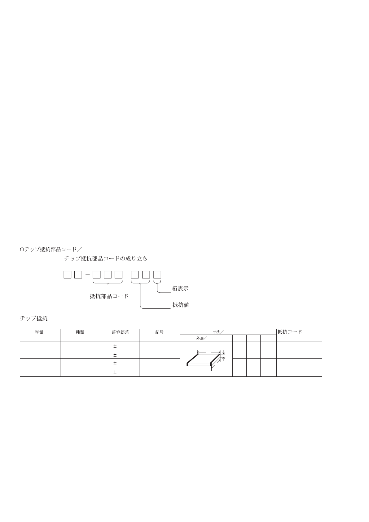
CHIP RESISTOR PART CODE
Chip Resistor Part Coding
88
A
Resistor Code
Chip resistor
Wattage Type Tolerance
1/16W 1005 5% CJ
1/16W
1/10W
1/8W
1608
2125
3216
5%
5%
5%
Symbol
CJ
CJ
CJ
Figure
Value of resistor
Form
L
Dimensions (mm)
t
W
0.55
Resistor Code
108
118
128
LW t
1.0 0.5 0.35 104
1.6 0.8 0.45
2 1.25 0.45
3.2
1.6
: A
: A
– 13 –
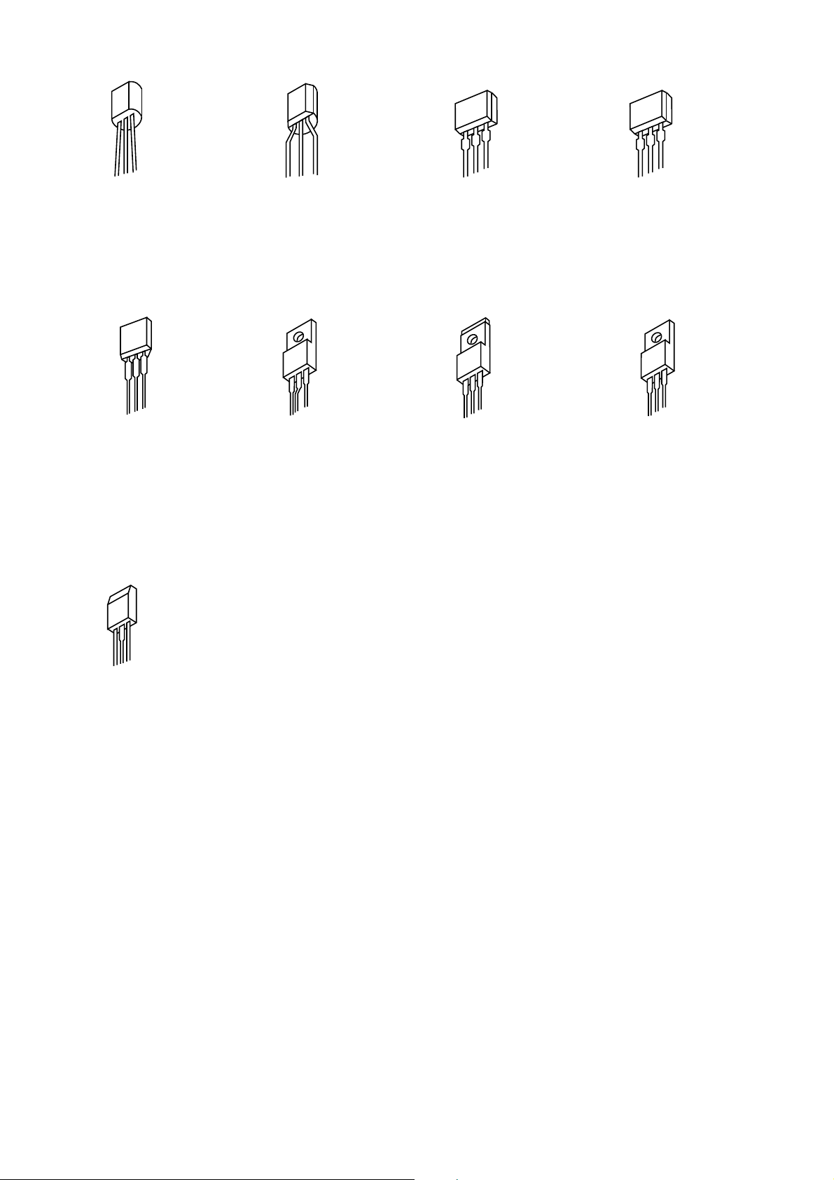
TRANSISTOR ILLUSTRATION
E C B B E C
2SC3467D/E
2SC3779D/E 2SJ460
2SA1015GR
E C B
2SC1740SRS
B C E
2SD2580
DTC144ES
2SA933SRS
2SA1175FE
E C B S D G
2SA950
2SC2785FE
2SK2541
DTC323TS
B C E
2SD2531
2SC5147D
2SC4793
2SA1837
B C E
E C B
2SD774
– 14 –
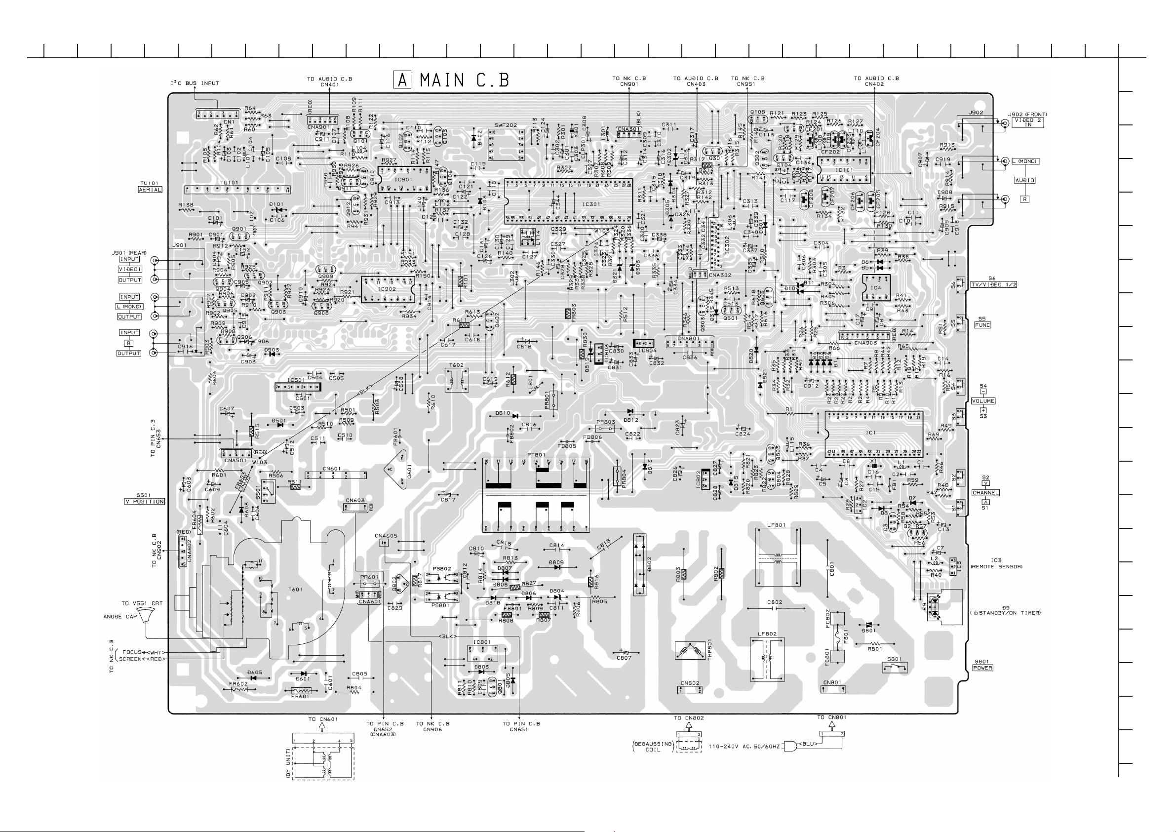
WIRING – 1 (MAIN)
101112131415161718192021222324
1234567892526272829303132
A
B
C
D
E
F
G
H
I
J
K
L
M
N
O
P
Q
– 15 –
R
S
T
U
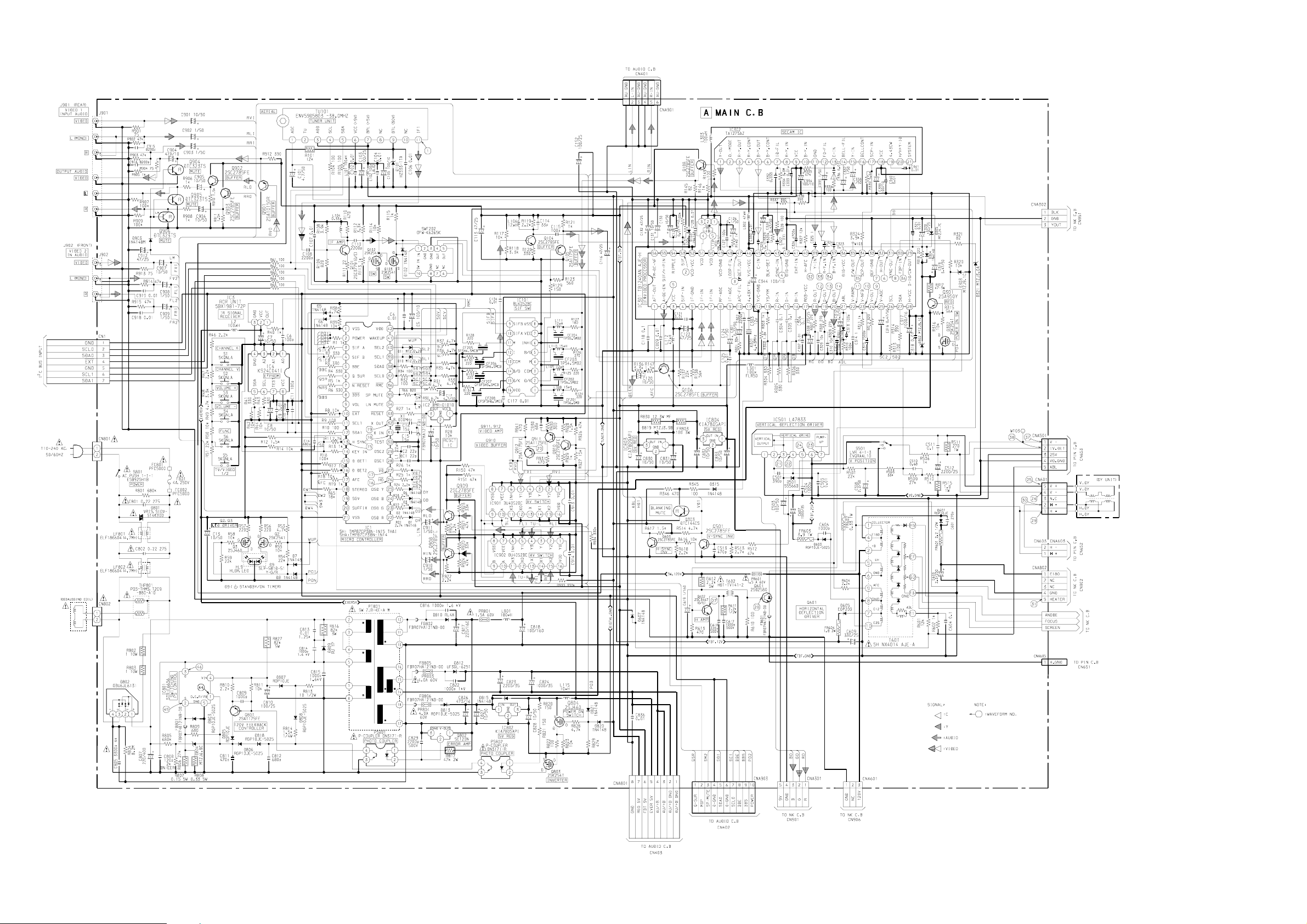
SCHEMATIC DIAGRAM – 1 (MAIN)
– 16 –
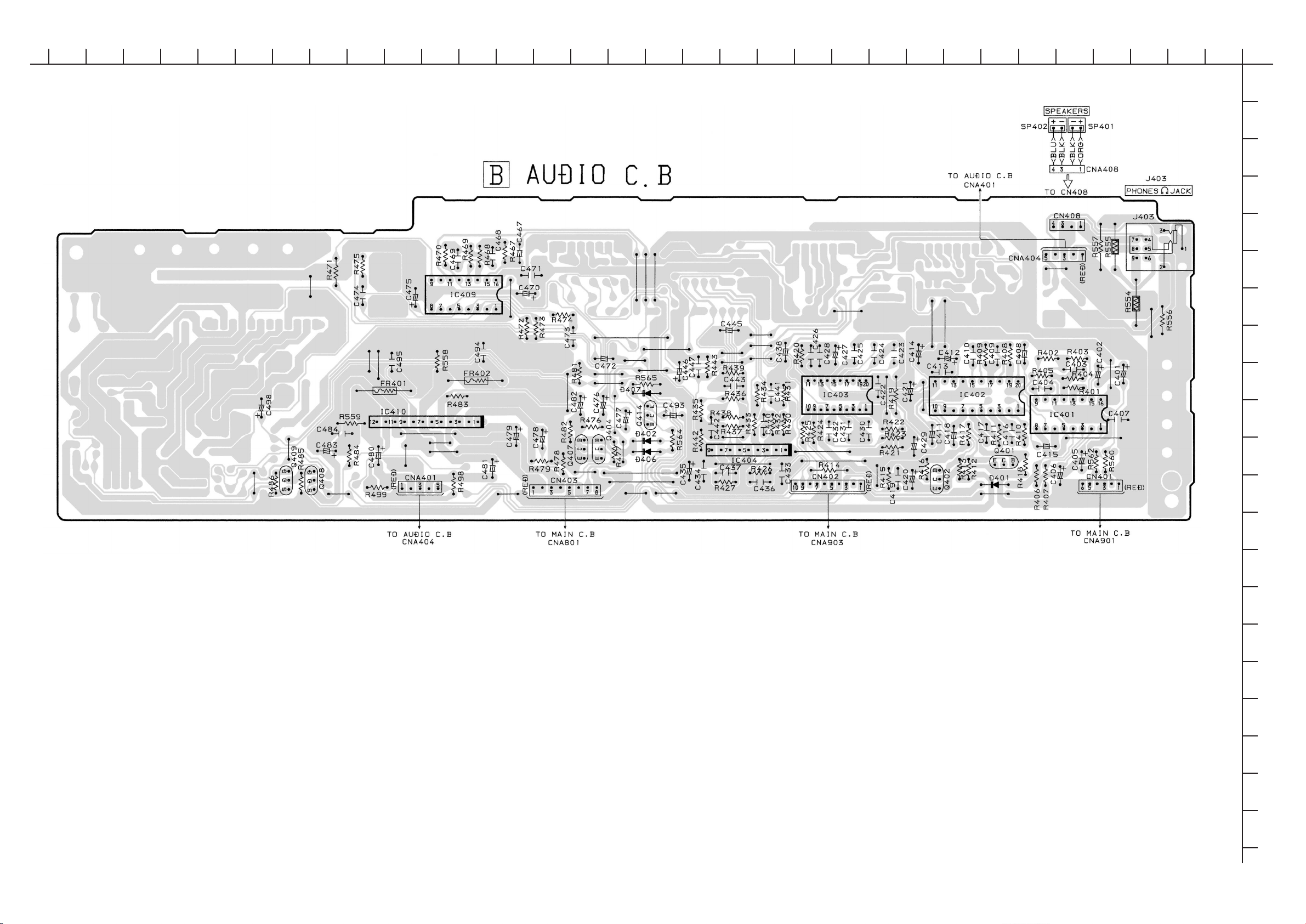
WIRING – 2 (AUDIO : SH)
101112131415161718192021222324
1234567892526272829303132
A
B
C
D
E
F
G
H
I
J
K
L
M
N
O
P
Q
– 17 –
R
S
T
U
WIRING – 3 (AUDIO : SHA)
101112131415161718192021222324
1234567892526272829303132
A
B
C
D
E
F
G
H
I
J
K
L
M
N
O
P
Q
– 18 –
R
S
T
U
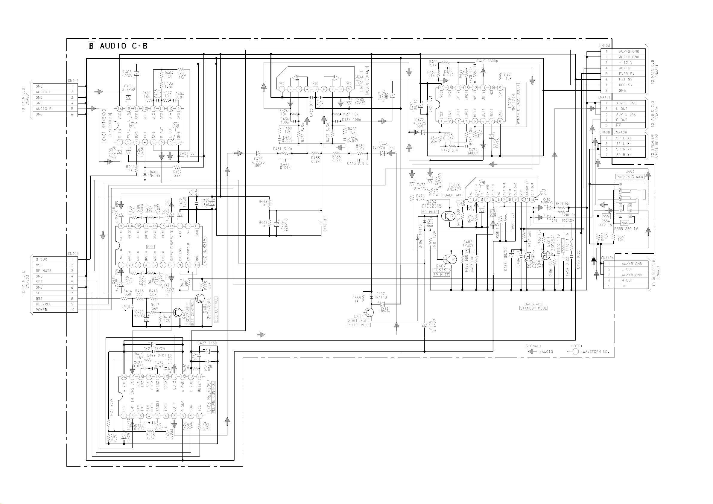
SCHEMATIC DIAGRAM – 2 (AUDIO : SH,SHA)
– 19 –
 Loading...