

Aiwa TV-C1400 Service Manual
TV-C1400
PO
W
E
R
TEXT
C1400
KY EZY KHY
SERVICE MANUAL
COLOR TELEVISION
SIMPLE-2
Apartofcontentsisadequate.
Re-issuing is under request.
S/M Code No. 09-009-352-0N1
DATA
NOTICES BEFORE REPAIRING
To make the best use of this equipment, make sure to
obey the following items when repairing (or mending).
1. Do not damage or melt the tunicate of the leading
wire on the AC1 side, including the power supply
cord.
2. Do not soil or stain the letters on the spec.
inscription plates, notice labels, fuse labels, etc.
3. When repairing the part extracted from the
conducted side of the board pattern, fix it firmly
with applying bond to the pattern and the part.
4. Restore the following items after repairing.
1) Conditions of soldering of the wires (especially,
the distance on the AC1 side).
2) Conditions of wiring, bundling of wires, etc.
3) Types of the wries.
4) Attachment conditions of all types of the insulation.
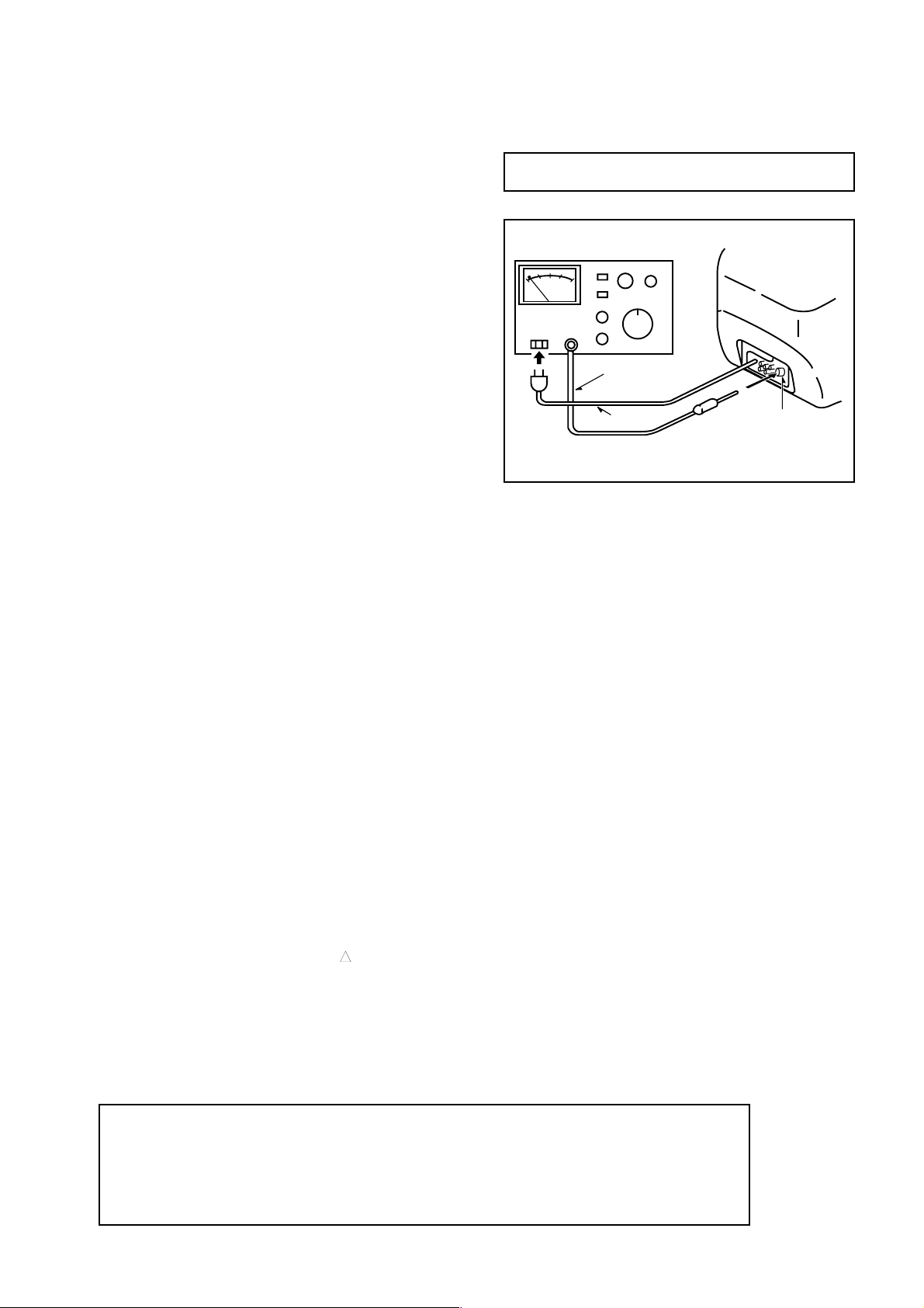
5. After repairing, always measure the insulation
resistance and perform the voltage-withstand test
(See Fig-1).
1) The insulation resistance must be 7.3 MΩ to 10.1 MΩ
when applying
2) In the voltage withstand test, apply 3.0 kV for 1
minute and check that the GO lamp lights.
500V per second.
Insulation resistance: 7.3 MΩ to 10.1 MΩ(500 V/s)
Voltage-withstand: 3.0 kV for 1 minute
Safety checker (Model 7110, etc.)
Earth cable
AC cable
Fig-1
Connect the earth cable
to the outside metal part
terminal.
* Breaking current set to 10 mA.
* Connect the safety checker as shown in Fig-1,
then measure the resistance and perform the test.
* Do not touch the equipment during testing.
* For details of the safety checker, refer to the supplied
Operation manual.
When servicing and checking on the TV, note the followings.
1. Keep the notices
As for the places which need special attentions, they
are indicated with the labels or seals on the cabinet,
chassis and parts. Make sure to keep the indications
and notices in the operation manual.
2. Avoid an electric shock.
There is a high voltage part inside. Avoid an electric
shock while the electric current is flowing.
3. Use the designated parts.
The parts in this equipment have the specific
characters of incombustibility and withstand voltage
for safety.
Therefore, the part which is replaced should be used
the part which has the same character. Especially as
to the important parts for safety which is indicated in
the circuit diagram or the table of parts as a mark,
the designated parts must be used.
4. Put parts and wires in the original position after
assembling or wiring.
There are parts which use the insulation material
such as a tube or tape for safety, or which are
assembled so that these parts do not contact with
the printed board. The inside wiring is designed not
!
to get closer to the pyrogenic parts and high voltage
parts. Therefore, put these parts in the original
positions.
5. Take care of the cathode-ray tube.
By setting an explosion-proof cathode-ray tube is set
in this equipment, safety is secured against
implosion.
However, when removing it or serving from
backward, it is dangerous to give a shock. Take
6. Avoid an X-ray.
Safety is secured against an X-ray by considering
peripheral circuit, etc. Therefore, when repairing the
high voltage peripheral circuit, use the designated
parts and do not change the circuit. Repairing
except indicates causes rising of high voltage, and
the cathode-ray tube emits an X-ray.
7. Perform a safety check after servicing.
Confirm that the screws, parts and wiring which were
removed in order to service are put in the original
positions, or whether there are the portions which are
deteriorated around the places serviced.
enough care to deal with it.
about the cathode-ray tube and the high voltage
!
Safety Components Symbol
This symbol is given to important parts which serve to maintain the safety of the product, and which
are made to confirm to special Safety Specifications.
Therefore, when replacing a component with this symbol make absolutely sure that you use a
designated part.
-2-

SPECIFICATIONS
Tuner system Frequency synthesized tuner
Picture tube 14 in. (34 cm “V”), 90 degree deflection
TV system PAL (B/G, D/K, I), SECAM (D/K, L)
Channel coverage VHF: E2-E12
UHF: E21-E69
CABLE: S1-S41
Antenna input 75 ohms, unbalanced
Video input 1.0 Vp-p, 75 ohms, unbalanced
Video output 1.0 Vp-p, 75 ohms, unbalanced
Audio input -3.8 dBs, 50 kohm
Audio output -3.8 dBs less than 1 kohm
Operating temperature 5°C to 40°C
Power requirements 220-240 V AC, 50 Hz
Power consumption 58 watts
Standby 2 watts
Dimensions 364(W) x 315(H) x 364(D) mm
(143/8 x 121/2 x 143/8 in.)
Weight Approx. 10.5 kg (23.1 lbs.)
• Design and specifications are subject to change without notice.
ACCESSORIES LIST
REF. NO PART NO. KANRI DESCRIPTION
1 8A-JB8-901-010 IB,K (E) -C1400<KY>
1 8A-JB8-903-010 IB,EZ (EGDSI)<EZY>
1 8A-JB8-904-010 IB,KH (E/R/CZ/PO) -C1400<KHY>
2 8A-JB4-610-010 RC UNIT,RC-AVT02
NO.
-3-
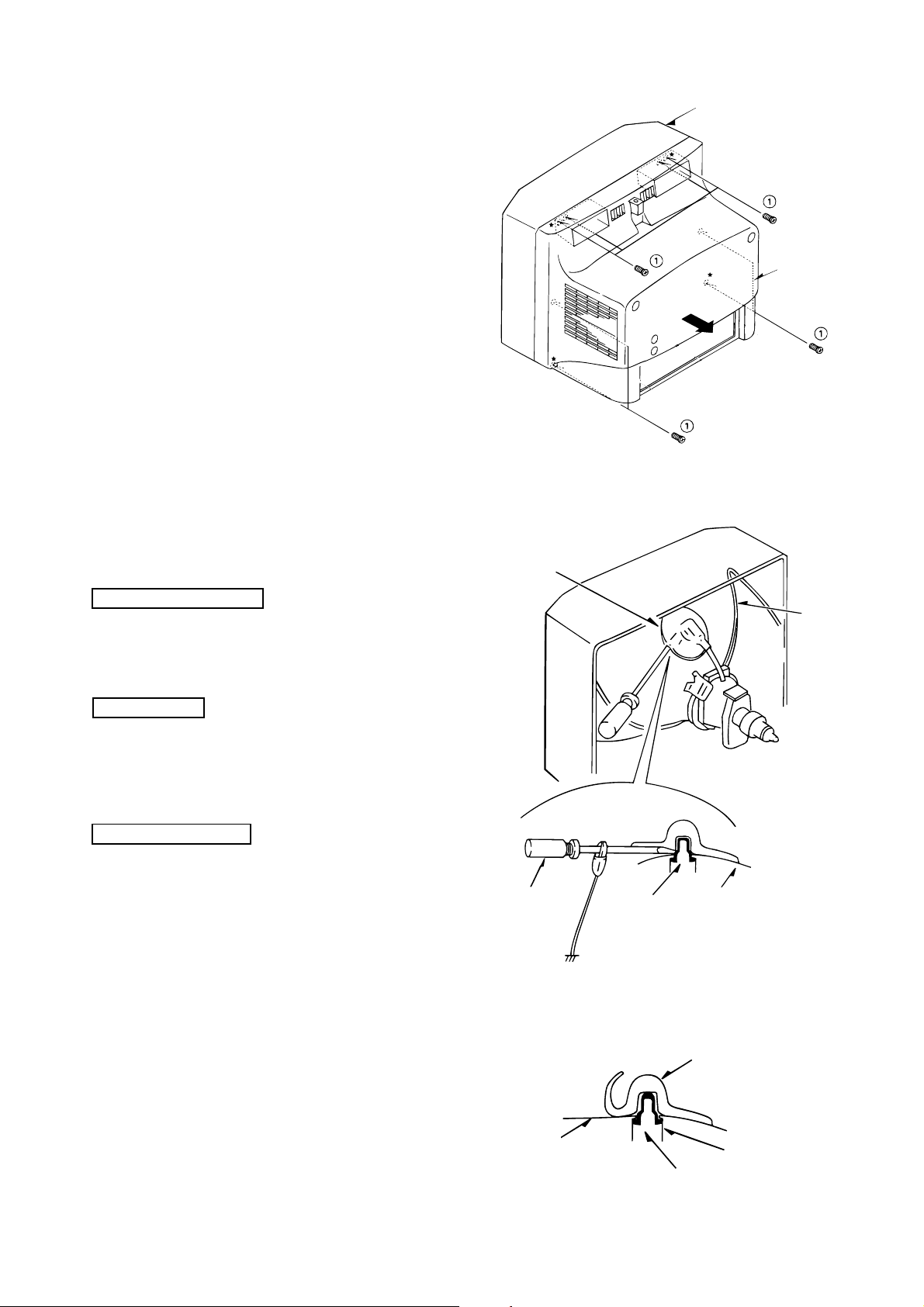
DISASSEMBLY INSTRUCTIONS
1. REAR CABINET REMOVAL
(1) Remove eight screws 1, then remove the rear cabinet in
the direction of the arrow.
(See Figure1-1)
2. HIGH-VOLTAGE CAP (ANODE CAP) REMOVAL
Front cabinet
Rear cabinet
Figure 1-1
2-1. Cautions before Removing
Discharge the anode voltage
(1) The anode voltage is not discharged completely from the
CRT of this unit even after the power is turned off. Be
sure to discharge the residual anode voltage before
removing the anode cap.
Do not use pliers
(2) Do not use pliers, etc. to remove the anode cap. If you
used pliers and bent the hook to remove the cap, the spring
characteristics of the hook could be lost, and when
reinstalled, the cap would come off from the CRT anode
button easily, causing an accident.
Do not turn the anode cap
(3) If the anode cap is turned in the direction of its
circumference, the hook is likely to come off.
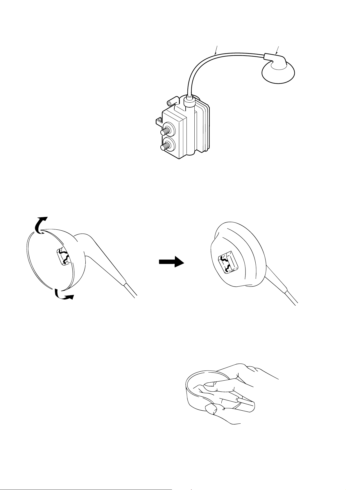
2-2. Anode Cap Removal
Anode cap
Grip
CRT GND
Hook
CRT GND
CRT
Figure 2-1
Discharge the anode voltage. (See Figure 2-1)
(1) Connect a flat-bladed screwdriver to the CRT GND via
an alligator clip.
(2) Use a tester to check the end of the screwdriver and ground
of the TV for continuity.
(3) Touch the hook with the end of the screwdriver.
Caution : Be careful not to damage the anode cap.
(4) Turn over the anode cap.
Caution : Be careful not to damage the anode cap.
-4-
CRT
Anode cap
Anode button
Hook
Figure 2-2
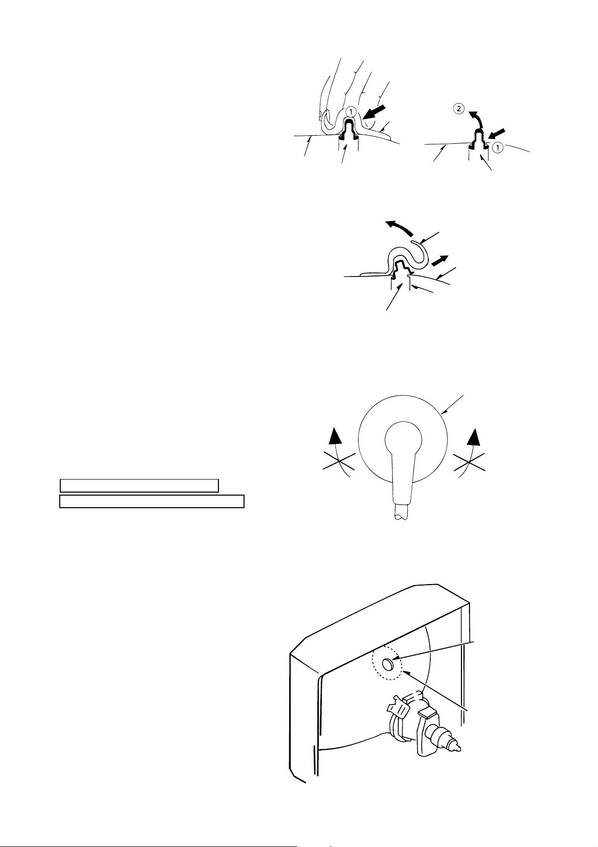
(5) Push the anode cap with your thumb in the direction of
arrow 1 as shown in the figure, then lift the cap in the
direction of arrow 2 to release the hook on one side.
(See Figure 2-3)
Anode cap
(6) Turn over the anode cap on the side where the hook was
released and pull out the cap in the direction opposite to
that on which the cap was pushed. (See Figure 2-4)
Caution : Do not pull out the anode cap straight up.
: Do not pull the cap forcibly. After removing
the cap, check that the hook is not deformed.
3. ANODE CAP REINSTALLTION
Observe the cautions carefully so that no accident occurs
due to a defect in installing the anode cap and so it does
not come off.
CRT
Hook
Left
CRT
Hook
Figure 2-3
Anode cap
CRT
Anode button
Hook
Figure 2-4
Anode cap
Right
3-1. Caution before Reinstalling
Never turn the anode cap after installing it
Never re-use the hook when it has been deformed
(1) If the anode cap is turned after it is installed, it may come
off. Therefore, arrange the high-voltage cable before
attaching the anode cap. (See Figure 3-1)
(2) If you have attached the anode cap before arranging the
high-voltage cable, arrange the cable carefully so the cap
does not turn.
3-2. Anode cap reinstallation
(1) Use a clean cloth moistened slightly with alcohol to clean
the installation section. (See Figure 3-2)
Caution : Check that the installation section is free from
dust, foreign matter, etc.
(2) Coat the anode cap installation circumference with an
appropriate amount of the specified silicone grease (KS650N).
Caution : Be careful that silicone grease does not enter
the anode button.
Figure 3-1
Anode button
Installation
section
-5-
Figure 3-2
(3) Eliminate twisting, etc. of the high-voltage cable and
arrange it so that no twisting occurs. (See Figure 3-3)
Caution : If the cable is not arranged correctly, the anode
cap could turn and cause an installation defect.
(4) Turn over the rubber cap symmetrically on the left and
right. (See Figure 3-4)
Caution : Take great care not to damage the anode cap.
High-voltage cable
Anode cap
Figure 3-3
(5) Fit your forefinger over the projection at the center of the
cap and hold the cap between your thumb and middle
finger. (See Figure 3-5)
Figure 3-4
Figure 3-5
-6-
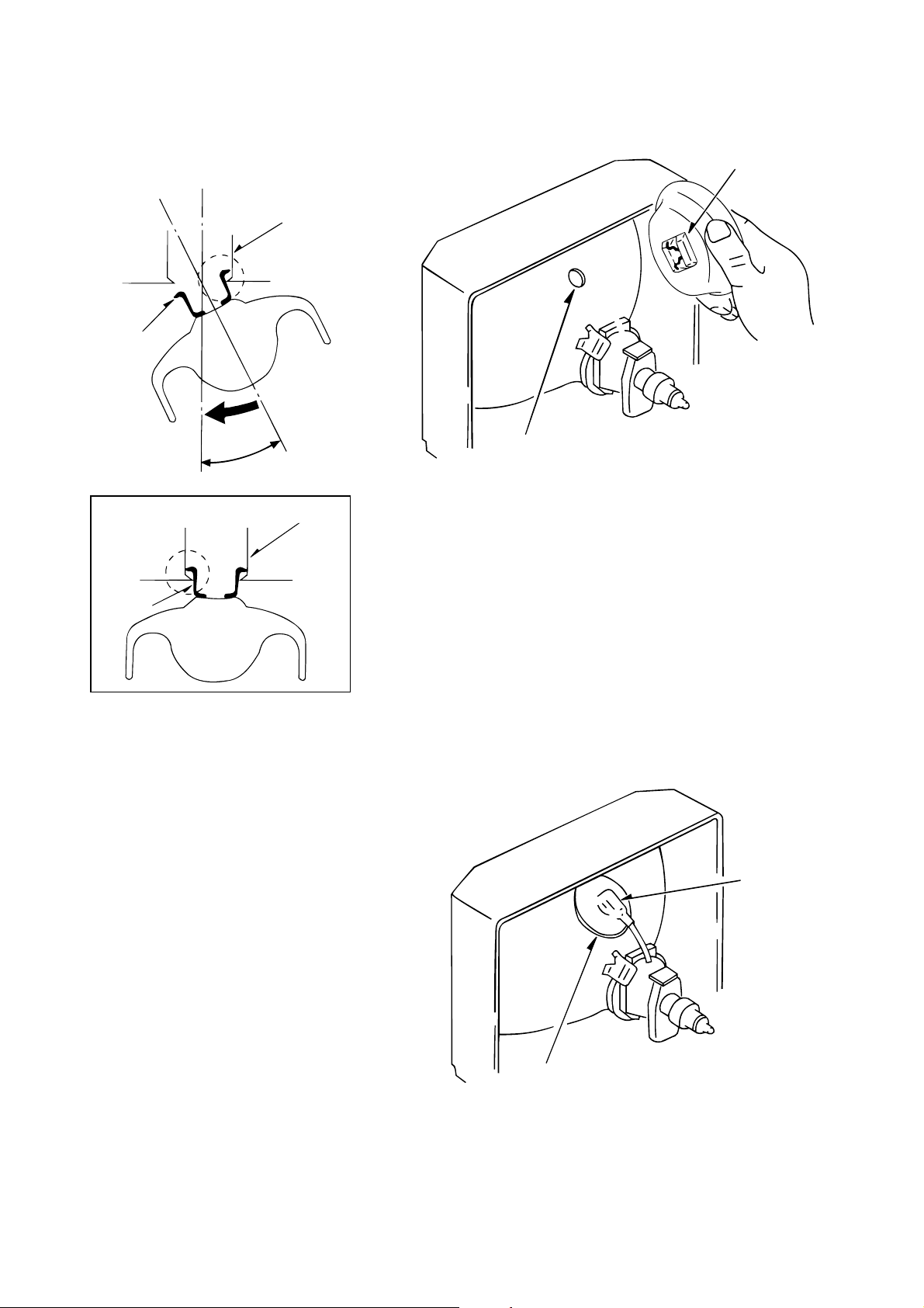
(6) Apply the hook on one side to the anode button as shown
on the figure. (See Figure 3-6)
Caution : Check that the hook is held securely.
(7) Apply the hook on the other side to the anode button as
shown in Figure 3-7.
Anode button
Hook
Hook
Anode button
30°
Anode button
Hook
Figure 3-7
(8) Pull the anode cap slightly with the rubber cap turned
over and visually check that the hook is engaged securely.
(9) Release your hand from the rubber cap of the anode cap.
Caution : Cover the anode cap so that it does not lift.
(10) Hold the skirt of the andoe cap slightly to improve the
close contact between the cap and CRT.
(11) Check that the anode cap is in close contact with the CRT.
(See Figure 3-8)
Figure 3-6
Anode button
-7-
Skirt
Figure 3-8
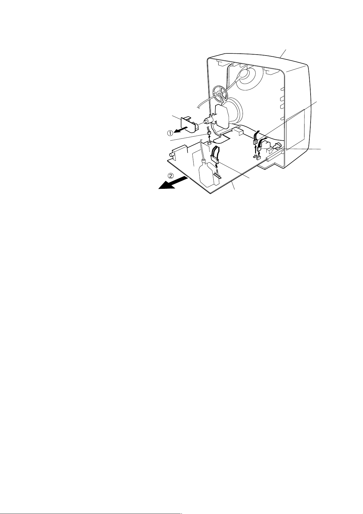
4. NECK C.B. REMOVAL
(1) Remove the NECK C.B. in the direction of arrow 1
(See Figure 4-2).
5. MAIN C.B REMOVAL
(1) Remove connector (P601).
(2) Remove connector (P801).
(3) Remove connector (P802).
(4) Remove connector (P401).
(5) Pull out the MAIN C.B. in the direction of
the arrow 2 (See Figure 4-2).
NECK C.B
P601
(Speakers
Main C.B
P401
Front Cabinet
P802
(Degauss
Cord)
P801
(Power Cord)
-8-

ELECTRICAL MAIN PARTS LIST
REF. NO PART NO. KANRI DESCRIPTION
IC
SI-AL2-416-00B IC,AT24C16-10PC
S1-DW1-95D-E2Q C-IC,DW92195B7T-DE2
S1-KA7-805-000 IC,KA7805
S1-KRT-300-000 IC,KRT30
S1-STV-223-8DQ C-IC,STV2238D
!!
! S4-850-M04-710 MODULE POWER DPM001T1A
!!
S1-STV-813-100 IC,STV8131
87-JB1-605-010 IC,TDA1771
S1-TDA-610-3Q0 IC,TDA6103Q
S1-TDA-726-7A0 IC,TDA7267A
TRANSISTOR
87-A30-492-080 TR,2SC5343Y
ST-KTC-320-700 TR,KTC3207
87-A30-050-010 TR,2SD2499
ST-R33-300-9DB TR,STA933-Y
!!
! ST-2SK-267-100 TR,2SK2671
!!
ST-KSA-101-3Y0 TR,KSA1013Y
DIODE
87-A40-246-080 DIODE,1N4148
SD-1SS-85T-A00 DIODE,1SS85TA
SD-UZ3-3B0-000 ZENER,UZ-33B
SD-TZX-5V1-B00 ZENER,TZX5V1B
SD-BYW-360-000 DIODE,BYW36
SD-BY2-280-000 DIODE,BY228
SD-TZX-5V6-B00 ZENER,TZX5V6B
SD-UZ3-R9B-000 ZENER,UZ-3.9B
SD-BYW-760-000 DIODE,BYW76
SD-BYW-340-000 DIODE,BYW34
SD-R2M-000-000 ZENER,R2M
SD-LT2-A05-G00 DIODE,LT2A05G
MAIN C.B
C101 87-015-695-010 CAP,E 1MF-50V
C102 87-010-408-040 CAP,E 4.7MF-50V
C103 87-010-285-010 CAP,E 2200MF-16V
C301 87-016-593-080 CAP,E 470MF-35V
C302 SC-CXB-3A4-71K CAP,CER 4700PF-1KV
C303 87-A10-493-080 CAP,E 1000MF-25V
C304 87-016-638-080 CAP,E 22MF-50V
C306 87-010-393-010 CAP,E 100MF-35V
C313 87-015-695-010 CAP,E 1MF-50V
C401 SC-MYE-2D3-64J CAP,M 0.36MF-200V
C402 S0-E7T-B01-0M0 CAP,E 1MF-160V
C404 SC-MYT-3C6-92J CAP,M 6900PF-1.6KV
C406 87-010-976-010 CAP,CER 1000PF-500V
C411 SC-MYN-1J1-05K CAP,M 1MF-63V
C420 87-010-553-080 CAP,E 47MF-16V
C421 87-010-545-080 CAP,E 33MF-250V
C501 87-015-694-080 CAP,E 0.47MF-50V
C502 87-015-695-010 CAP,E 1MF-50V
C503 87-010-553-080 CAP,E 47MF-16V
C504 87-015-696-080 CAP,E 2.2MF-50V
C506 87-015-696-080 CAP,E 2.2MF-50V
C507 87-010-112-040 CAP,E 100MF-16V
C511 87-010-553-080 CAP,E 47MF-16V
C512 87-015-695-010 CAP,E 1MF-50V
C513 87-010-405-040 CAP,E 10MF-50V
C514 87-015-695-010 CAP,E 1MF-50V
C515 87-015-695-010 CAP,E 1MF-50V
C516 87-015-695-010 CAP,E 1MF-50V
C517 87-015-695-010 CAP,E 1MF-50V
C520 87-010-553-080 CAP,E 47MF-16V
C522 87-010-553-080 CAP,E 47MF-16V
NO.
REF. NO PART NO. KANRI DESCRIPTION
C523 87-015-695-010 CAP,E 1MF-50V
C524 87-015-695-010 CAP,E 1MF-50V
C601 87-010-553-080 CAP,E 47MF-16V
C602 87-010-544-080 CAP,E 0.1MF-50V
C606 87-016-126-080 CAP,E 470MF-16V
C611 87-010-553-080 CAP,E 47MF-16V
C620 87-010-405-040 CAP,E 10MF-50V
C702 87-015-695-010 CAP,E 1MF-50V
C703 87-010-553-080 CAP,E 47MF-16V
C704 87-010-237-910 CAP,E 1000MF-16V
C706 87-015-694-080 CAP,E 0.47MF-50V
C801 SC-L1S-C34-74M CAP,0.47MF-275V
C803 SC-CXF-3A4-72Z CAP,CER 4700PF-1KV
C804 SC-CXF-3A4-72Z CAP,CER 4700PF-1KV
C805 87-A10-003-090 CAP,E 100MF-400V
C807 SC-MYU-3C2-22J CAP,M 2200PF-1.6KV
C809 87-A12-170-010 CAP,CER 1000PF-4.0KV
C812 87-A12-170-010 CAP,CER 1000PF-4.0KV
C814 SC-CYR-3A4-71K CAP,CER 470PF-1KV
C815 87-016-249-090 CAP,E 100MF-160V
C818 87-016-249-090 CAP,E 100MF-160V
C819 87-016-299-080 CAP,E 10MF-100V
C820 87-A10-493-080 CAP,E 1000MF-25V
C822 87-010-112-040 CAP,E 100MF-16V
C825 87-016-638-080 CAP,E 22MF-50V
C826 87-010-408-040 CAP,E 4.7MF-50V
C827 87-010-285-010 CAP,E 2200MF-16V
C828 87-010-112-040 CAP,E 100MF-16V
C829 87-010-405-040 CAP,E 10MF-50V
C830 87-016-126-080 CAP,E 470MF-16V
C842 87-016-515-080 CAP,CER 1000PF-1KV
C850 87-010-553-080 CAP,E 47MF-16V
D706 SD-LH2-PR0-000 LED BLOCK LH-2P-R
!!
!F801 S5-FSC-B40-22R FUSE CERA 4A 250V
!!
JS02 S4-859-109-950 JACK PIN BOARD PH-JB-9710A
L101 S5-8N0-000-044 COIL VCO TRF-V010
L301 S5-CPZ-100-K04 COIL PEAKING 10UH 10.5MM
L511 S5-CPZ-100-K02 COIL PEAKING 10UH 3.5MM
L601 S5-CPZ-109-M02 COIL PEAKING 1UH 3.5MM
L602 S5-CPZ-109-M02 COIL PEAKING 1UH 3.5MM
L604 S5-CPZ-109-M02 COIL PEAKING 1UH 3.5MM
L701 S5-CPZ-100-K02 COIL PEAKING 10UH 3.5MM
L702 S5-CPZ-569-K02 COIL PEAKING 5.6UH 3.5MM
L800 S5-8Q0-000-093 COIL DELAY LINE RS208
!!
!L801 S5-PLF-24A-300 FILTER LINE LF-24A3
!!
L802 S5-MC0-000-100 COIL BEAD MD-5
L803 S5-MC0-000-100 COIL BEAD MD-5
L805 S5-8C4-500-079 COIL CHOKE L-45
L806 S5-CPZ-390-K04 COIL PEAKING 39UH 10.5MM
P101 S4-859-231-620 CONN WAFER YW025-03
P401 S4-859-240-020 CONN WAFER YFW500-05
P601 S4-859-231-620 CONN WAFER YW025-03
!!
!P801 S4-859-287-320 CONN WAFER MKS2822
!!
P802 S4-859-242-220 CONN WAFER YFW800-02
P601A S4-850-703-S50 CONN AS YH025
R302 87-022-576-010 RES,R METAL 2.2-2W
R303 87-022-642-090 RES,R METAL 270-2W
R307 SR-N02-B18-1JS RES,R METAL 180-2W
R308 SR-N02-B18-1JS RES,R METAL 180-2W
R309 SR-N02-B18-1JS RES,R METAL 180-2W
R310 SR-N02-B18-1JS RES,R METAL 180-2W
R402 87-025-590-060 RES,R M-OXIDE 15K-2W
!!
!R403 SR-S02-Y43-9JS RES,R M-OXIDE 4.3-2W
!!
R410 SR-N02-B13-2JS RES,METAL 1.3K-2W
R503 SR-N01-B30-0JS RES,METAL 30-1W
!!
!R801 SD-EC1-40M-290 POSISTOR ECPCC140M290
!!
R802 SR-X07-C33-9JF RES,CEM 3.3-7W
R808 SR-S02-Y82-8JS RES,R M-OXIDE 0.82-2W
R819 SR-S02-Y27-8JS RES,R M-OXIDE 0.27-2W
R850 87-A00-618-090 RES,METAL 18-2W
NO.
-9-
 Loading...