

:.-ï-
=■’ >-
í;í'?íí;í:-
iiiiifei
Î5?
COMPACT DISC STEREO SYSTEM
SISTEMA ESTEREOFONICO DE DISCO COMPACTO
CHAINE STEREO AVEC LECTEUR DE DISQUES COMPACTS
LCX-300
LCX-301
OPERATING INSTRUCTIONS
MANUAL DE INSTRUCCIONES
MODE D’EMPLOI
IÍDS®
DIGITAL AUDIO
/
For Assistance And Information
Call Toll Free 1-800-BUY-AIWA
(United States and Puerto Rico)
V
LCX-300
U I K I LH
J
LCX-301
U
OWNER’S RECORD WARNING
For your convenience, record the model number and serial
number (you will find them on the rear of your set) in the space
provided below. Please refer to them when you contact your AIWA
dealer in case of difficulty.
Model No. Serial No. (Lot No.)
LCX-300 U, K, LH,
LCX-301 U
CAUTION (K model)
Use of controls or adjustments or performance of procedures
other than those specified herein may result in hazardous
radiation exposure.
ATTENTION
L’utilisation de commandes, réglages ou procédures autres que
ceux spécifiés peut entraîner une dangereuse exposition aux
radiations.
This compact dise player is classified as a CLASS 1 LASER
product.
The CLASS 1 LASER PRODUCT label is located on the exterior.
TO REDUCE THE RISK OF FIRE OR ELECTRIC
SHOCK, DO NOT EXPOSE THIS APPLIANCE TO
RAIN OR MOISTURE.
CAUTION
RISK OF ELECTRIC SHOCK
DO NOT OPEN
“CAUTION: TO REDUCE THE RISK OF
ELECTRIC SHOCK,
DO NOT REMOVE COVER (OR BACK).
NO USER-SERVICEABLE PARTS INSIDE.
REFER SERVICING TO QUALIFIED
SERVICE PERSONNEL.”
Explanation of Graphical Symbols:
The lightning flash with arrowhead symbol, within an
equilateral triangle, is intended to alert the user to
A
the presence of uninsulated "dangerous voltage"
within the product's enclosure that may be of suffi-.
dent magnitude to constitute a risk of electric shock
to persons.
The exclamation point within an equilateral triangle
is intended to alert the user to the presence of
important operating and maintenance (servic
ing) instructions in the literature accompanying
the appliance.
CAUTION!
Invisible laser radiation when open and inter
locks defeated. Avoid exposure to beam.
ADVARSEL!
Usynlig laserstáling ved âbning, nâr sikkerhedsafbrydereer ude
af funktion. Undgä udsættelse for strâling.
VAROITUS!
Laitteen käyttäminen muulla kuin tässä käyttöohjeessa mainitulla
tavalla saattaa altistaa käyttäjän turvallisuusluokan 1 ylittävälle
näkymättömälle lasersäteiylle.
YARNING!
Om apparaten anvands pa annat satt an i denna bruksanvisning
specificerats, kan anvandaren utsatta for osynlig laser-straining,
som dverskrider gransen for laserklass 1.
OBSERVERA
Sâ länge som apparaten är ansluten till nätet flyter en svag ström
genom densamma, även dâ den är avstängd. Om man under en
längre tid ej har för avsikt att använda den, drag dâ ur nätkabeln.
BEMÆRK
Apparatet er stadig forbundet med lysnettet, sä længe stikket er
tilsluttet til stikkontakten, selv om afbryteren er släetfra. Hvis
apparatet ikke bruges i længere tid, skal netledningen trakkes
ud.

WARNING
FOR USE IN THE UNITED KINGDOM (K model only)
This appliance is supplied with a fitted three pin mains plug. A 3
amp fuse is fitted in the plug
Should the fuse need to be replaced, use a 3 amp fuse approved
byASTAor BSI to BS1362. When replacing the fuse, you must
ensure that any removable fuse covers are correctly refitted
If you should lose the fuse cover, please contact your nearest
AIWA dealer.
DO NOT CUT OFF THE PLUG FROM THIS APPLIANCE. If the
plug fitted is not suitable for the power points in your home, or
the cable is too short to reach a power point, obtain an appropriate
safety approved extension lead or adaptor. If in any doubt please
consult a qualified electrician.
If the plug is cut off, remove the fuse and dispose of the plug
immediately. THERE IS A DANGER OF SEVERE ELECTRICAL
SHOCK IF THE CUT OFF PLUG IS INSERTED INTO ANY 13
AMP SOCKET.
If a new plug is to be fitted please ensure it contains a 3 amp
fuse, otherwise the circuit should be protected by a 5 amp fuse
at the distribution board.
IMPORTANT
The wires in this mains lead are coloured in accordance with the
following code:
BLUE
BROWN
As the colours of the wires in the mains lead of this appliance may
not correspond with the colour markings identifying the terminals
in your plug, proceed as follows:
The wire which is coloured BLUE must be connected to the
terminal which is marked by the letter N or coloured BLACK.
The wire which is coloured BROWN must be connected to the
terminal which is marked by the letter L or coloured RED.
DO NOT connect either the BLUE or BROWN wires in the mains
lead to the earth terminal (marked with the letter E or by the earth
symbol i or coloured GREEN or GREEN/YELLOW) of a 3 pin
plug.
NEUTRAL
LIVE
COPYRIGHT
Please check the laws on copyright relating to recordings from
discs, radio or external tape for the country in which the machine
is being used.
DERECHOS DE AUTOR
Compruebe las leyes sobre derechos de autor, del país en el que
se utilice el sistema, que estén relacionadas con la grabación de
discos, programas de radio o cintas.
DROITS D’AUTEUR
Prière de vérifier les lois sur la propriété artistique relatives à
l’enregistrement de disques, de la radio ou de cassettes dans le
pays d’utilisation de i’appareil.
NOTE
FOR USE IN THE U.S.A. (U model only)
This equipment has been tested and found to comply with the
limits for a Class B digital device, pursuant to Part 15 of the FCC
Rules. These limits are designed to provide reasonable protection
against harmful interference in a residential installation.
This equipment generates, uses, and can radiate radio frequency
energy and, if not installed and used in accordance with the
instructions, may cause harmful interference to radio
communications. However, there is no guarantee that interference
will not occur in a particular installation. If this equipment does
cause harmful interference to radio or television reception, which
can be determined by turning the equipment off and on, the user
is encouraged to try to correct the interference by one or more of
the following measures'
- Reorient or relocate the receiving antenna.
- Increase the separation between the equipment and
receiver.
- Connect the equipment into an outlet on circuit different
from that to which the receiver is connected.
- Consult the dealer or an experienced radio/TV technician
for help.
CAUTION
Modifications or adjustments to this product, which are not
expressly approved by the manufacturer, may void the user’s right
or authority to operate this product.
<г»t /4t6umi A^‘%-300/30t
(D
To optimize the performance of this system, please take the time
to read through these Operating Instructions and become familiar
with the operating procedures.
About your system
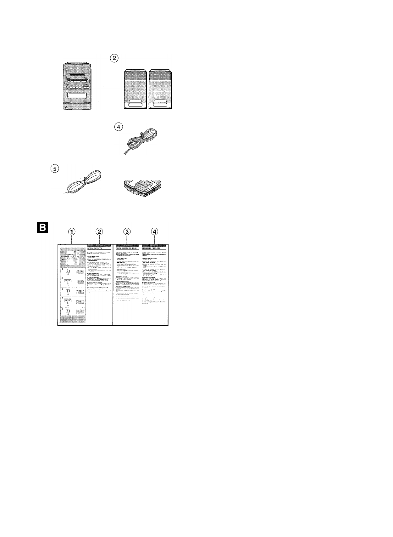
Your system LCX-300/301 is composed of the units © and
supplied with the accessories as follows. -> □
© Compact disc stereo cassette receiver LCX-300/301
@ Speakers
® Remote control
@ FM antenna (U and LH only)
® FM antenna (K only) ,
® AM (MW/LW) antenna
@ Operating Instructions, etc.
About this manual -* m
This manual contains illustrations © and instructions in three
languages ©-©.
© Illustration
® English
® Spanish
@ French
About the illustrations
Capital letters, bold face numbers, smaller numbers and lower
case letters in the instructions correspond to the letters and
numbers in the illustration column.
For example, the 0” following “About this manual” above
is a reference to illustration 0.
Model number suffix
The model number is marked on the rear panel of the unit. It
has a suffix that denotes the model type.
Example: MODEL NO. LCX-300 LH
i—suffix (LH)
Units with different suffixes differ in some details.
If suffixes are mentioned in the instructions, read the section
following the suffix for your unit.
4

*péUe4£<!tUo*ta. et cut
lex-soo/sot /ícwa
Para optimizar las presiaciones de este sistema, tome el tiempo
necesario para leer este manual de instrucciones y familiarizarse
con los procedimientos de funcionamiento.
Acerca de su sistema
EL sistema LCX-300/301 se compone de las unidades © , y se
suministra con los accesorios @ a @ sigún se muestra. -♦ 0
® Sintonizador, amplificador, platina de cassette y reproductor
de discos compactos estéreo LCX-300/301
® Altavoces
@ Control remoto
® Antena interior de FM (U y LH solamente)
® Antena interior de FM (K solamente)
® Antena de cuadro de AM (MW/LW)
@ Manual de instrucciones, etc.
Acerca de este manual 0
Este manual tiene ilustraciones © e instrucciones en tres idiomas
@-®.
© Ilustración
@ Inglés
@ Español
® Francés
Acerca de las ilustraciones
Las letras mayúsculas, los números en negrita, los números
pequeños y las letras minúsculas de las instrucciones
corresponden a las letras y números de las columnas de
ilustraciones.
Por ejemplo, 0 a continuación de “Acerca de este
manual”, que aparece más arriba, se refiere a la ilustración 0.
Sufijo del número del modelo
El número de modelo se Indica en el panel posterior de la
unidad.Y tiene un sufijo que indica el fipo del modelo.
Ejemplo: MODEL NO. LCX-300 LH
Sufijo (LH)
Los aparatos con distintos sufijos difieren en cuanto a algunos
detalles.
Si los sufijos están indicados en las instrucciones, sirvase leer
la sección correspondiente al sufijo de su aparato.
£e‘X-300/30t Aiwee
La lecture de ce mode d’emploi vous permettra de maîtriser
l’utilisation et d’optimiser les performances de cette chaîne.
Au sujet de la chaîne
Votre système LCX-300/301 se compose des appareils © et
est fourni avec les accessoires @ à @ comme suit.--» H
© Radio magnétocassette lecteur de disques compacts stéréo
LCX-300/301
@ Enceintes
@ Télécommande
® Antenne FM (U et LH uniquement)
® Antenne FM (K uniquement)
® Antenne AM(MW/LW)
@ Mode d’emploi, etc.
Au sujet de ce manuel -» 0
Ce manuei comporte des illustrations © et des instructions en
trois langues @ à @
© Illustration
@ Anglais
@ Espagnol
® Français
Au sujet des illustrations
Les lettres majuscules, les numéros en gras, les numéros plus
petits et les lettres minuscules correspondent aux lettres et
numéros de la colonne des illustrations.
Par exemple, le m ” qui suit “Au sujet de ce manuel ” cidessus renvoie à la partie
Suffixe du numéro de modèle
Le numéro de modèle est indiqué à l’arrière de l’appareil. Il
comparte un suffixe qui indique le type modèle.
Exemple: MODEL NO. LCX-300 LJH
Des appareils ne portant pas le même suffixe diffèrent dans
certains détails.
Si des suffixes sont mentionnés dans les instructions, lire la
section suivant le suffixe correspondant a l’appareil.
0
de l’illustration.
I—suffixe (LH)

TABLE OF CONTENTS
PREPARATIONS
PRECAUTIONS..................................................................8
CONNECTIONS..................................................................8
BEFORE OPERATION ....................................................12
SETTING THE CLOCK.....................................................14
SOUND
____________________________________
SIMPLE AUDIO ADJUSTMENT
EQUALIZER
RADIO RECEPTION
MANUAL TUNING........................................................... 18
PRESETTING STATIONS................................................20
PRESET NUMBER TUNING
____________________________
......................................
.....................................................................
__________________________
...........................................
16
16
20
CD PLAYING________________________________
BASIC OPERATIONS
PROGRAMMED PLAY.....................................................26
TAPE PLAYBACK
BASIC OPERATIONS
......................................................
22
___________________________
......................................................
28
RECORDING________________________________
BASIC RECORDING .......................................................30
KARAOKE
MICROPHONE MIXING
_________________________________
...................................................
32
OTHER CONNECTIONS_______________________
CONNECTING OPTIONAL EQUIPMENT
LISTENING TO EXTERNAL SOURCES..........................34
GENERAL
CARE AND MAINTENANCE............................................36
SPECIFICATIONS............................................................36
TROUBLESHOOTING GUIDE
PARTS INDEX..................................................................42
__________________________________
.........................................
........................
34
40
6

INDICE TABLE DES MATIERES
PREPARATIVOS
PRECAUCIONES..........................
CONEXIONES...............................
ANTES DE LA OPERACION
PUESTA EN HORA DEL RELOJ .
........
SONIDO
AJUSTE SENCILLO DEL SONIDO
ECUALIZADOR................................
RECEPCION DE LA RADIO
SINTONIZACION MANUAL
PREAJUSTE DE EMISORAS
SINTONIZACION MEDIANTE NUMERO DE
PREAJUSTE
..................................................
............................
.........................
REPRODUCCION DE DISCOS COlVIPACTOS
OPERACIONES BASICAS
REPRODUCCION PROGRAMADA
........................................
..........................
REPRODUCCION DE CINTAS
OPERACIONES BASICAS........................
.......................
GRABACION
GRABACION BASICA...............................
.......................
KARAOKE
MEZCLA MICROFONICA
.........................
.......................
OTRAS CONEXIONES
CONEXION DE EQUIPO OPCIONAL...............................35
ESCUCHA DE FUENTES DE SONIDO EXTERNAS
GENERALIDADES
CUIDADOS Y MANTENIMIENTO
ESPECIFICACIONES
GUIA PARA LA SOLUCION DE AVERIAS.
INDICE DE LAS PARTES.................................................43
________________
................
..................................
.......
...9
...9
.13
.15
,17
.17
.19
.21
.21
.23
.27
29
31
33
35
.37
.37
.41
PREPARATIONS
PRECAUTIONS..................................................................9
CONNEXIONS....................................................................9
AVANT L’UTILISATION...................................................13
REGLAGE DE L’HORLOGE............................................15
____________________________
SON_______________________________________
REGLAGE AUDIO SIMPLE
EGALISEUR.....................................................................17
.............................................
17
RECEPTION RADIO__________________________
ACCORD MANUEL..........................................................19
MEMORISATION DE STATIONS
ACCORD SUR UNE STATION MEMORISEE.................21
...................................
21
LECTURE DE DISQUES COMPACTS____________
OPERATIONS DE BASE
LECTURE PROGRAMMEE
.................................................
.............................................
23
27
LECTURE DE CASSETTES____________________
OPERATIONS DE BASE
.................................................
29
ENREGISTREMENT__________________________
ENREGISTREMENT DE BASE.......................................31
KARAOKE
MIXAGE AVEC MICROPHONE
_________________________________
.......................................
33
AUTRES CONNEXIONS_______________________
CONNEXION D’UN APPAREIL OPTIONNEL
ECOUTE DE SOURCES EXTERNES
.................
.............................
35
35
GENERALITES______________________________
SOINS ET ENTRETIEN....................................................37
SPECIFICATIONS............................................................37
EN CAS DE PROBLEME
NOMENCLATURE
................................................
...........................................................
41
43
7
PREPARATIONS
PRECAUTIONS
J
□
Follow the advice below for safe and correct operation.
This system may be powered by an AC voltage or car battery
(DC 12 V) power source. (Car battery cord is not supplied.)
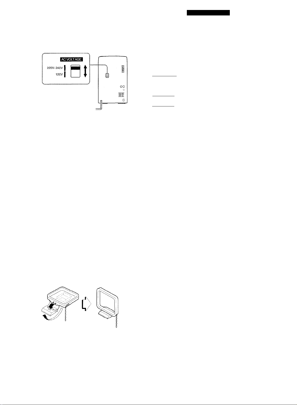
On AC voltage
Before connecting the AC cord, check that the rated voltage
shown on the rear panel matches your local voltage.
For LH model
AC 120/220-240 V, selectable.
To match your local voltage, switch the AC VOLTAGE selector
on the rear panel with a screwdriver or similar tool. -► □
For U model
AC 120 V, fixed.
For K model
AC 230 V, fixed.
On placement
• Do not use the system In places which are extremely hot, cold,
dusty or humid.
• Do not use the system in places which are subject to vibration.
• Place the system on a fiat, even surface.
• The unit should be situated with adequate space around it so
that proper heat ventilation is assured. Allow 10 cm (4 in.)
clearance from the rear and the top of the unit, and 5 cm (2 in.)
from each side.
In particular, do not place the system in an airtight rack.
• If using the system near a television or radio, noise may be
heard from the television, radio or this system. Move this system
away from the affected television or radio.
ID
On safety
• When disconnecting the AC cord or car battery cord, pull out
by the plug. Do not pull the cord itself.
• When the system is not used for an extended period of time,
disconnect the AC cord or car battery cord. When the cord is
plugged in, a small amount of current continues to flow to the
system, even when the power is turned off.
• If the AC cord is damaged, contact your dealer or an Aiwa
service center for immediate replacement or repair.
Should any trouble occur, disconnect the AC cord and car battery
cord and contact a qualified service representative.
CONNECTIONS
IMPORTANT
• Make sure the AC voltage matches your local voltage. (LH
model only)
• Connect the AC cord or car battery cord after connecting
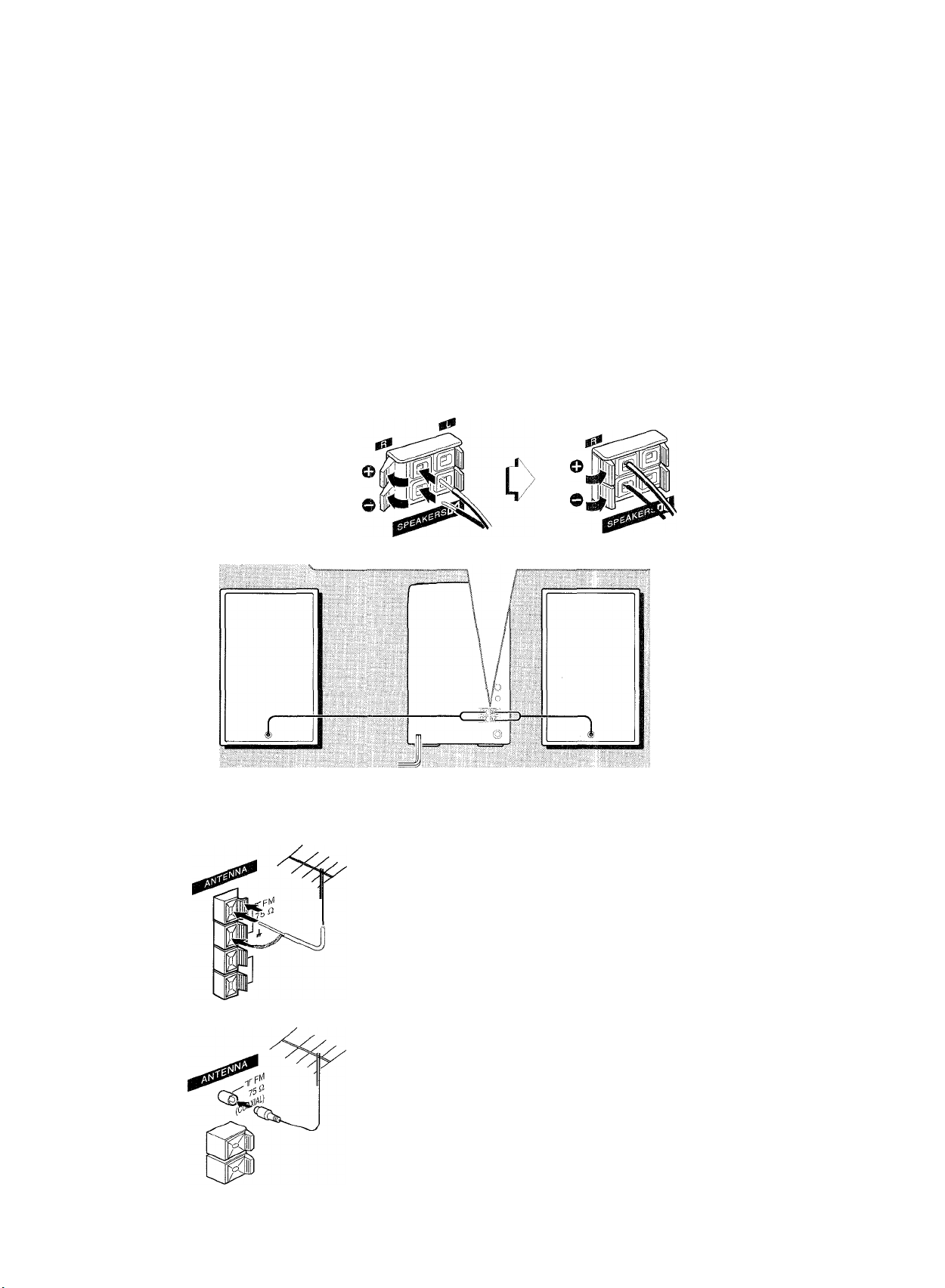
speakers, antennas, and all optional equipment.
• There are no differences between the speakers. Both speakers
can be connected as L (left) or R (right).
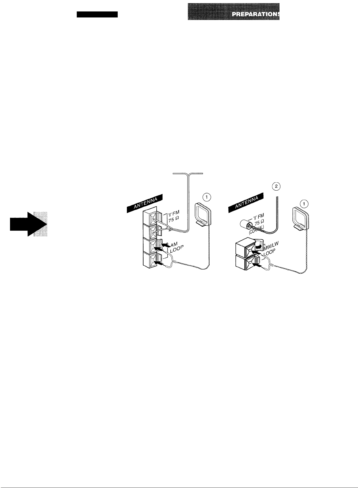
To Stand the AM antenna -► □
Fix the claw to the slot.
To position the antennas
FM feeder antenna: (For U and LH model only)
Extend this antenna horizontally in a T-shape and fix its ends to
the wall with cellophane tape, etc.
FM unipolar antenna: (For K model only)
Extend fully and position for the best possible reception.
This antenna is of an instant type, so the use of an outdoor
antenna is recommended.
AM (MW/LW) loop antenna:
Position to find the best direction and position for radio reception.
8

PREPARATIVOS
I
jggggjggmg
PRECAUCIONES
Siga los consejos dados a continuación para que el
funcionamiento sea seguro y correcto.
Este sistema puede alimentarse con CA o con una batería para
automóvil (CC 12 V). (No se proveen el cable de la batería para
automóvil.)
Acerca de la tensión de CA
Antes de conectar el cable de alimentación de CA, compruebe
si la tensión nominal mostrada en el panel trasero concuerda
con la tensión de su localidad.
Para el modelo LH
120/220-240 V CA, seleccionables.
Para que se ajuste con el voltaje local, cambie el selector AC
VOLTAGE del panel posterior con un destornillador o con una
herramienta similar.
Para el modelo U
120 VCA, fijo.
Para el modelo K
230 V CA, fijo.
Acerca del lugar de instalación
• No utilice el sistema en lugares extremadamente calientes,
fríos, polvorientos o húmedos.
• No utilice el sistema en lugares sometidos a vibraciones.
• Ponga el sistema sobre una superficie plana y nivelada.
• La unidad deberá situarse donde tenga suficiente espacio libre
a su alrededor, para que la ventilación apropiada quede
asegurada. Deje un espacio libre de 10 cm por la parte posterior
y superior de la unidad, y 5 cm por cada lado.
En particular, no ponga el sistema en un mueble cerrado.
• Si utiliza el sistema cerca de un televisor o de una radio, tal
vez se oigan ruidos en el televisor, en la radio o en este sistema.
Separe este sistema de la radio o del televisor afectado.
Acerca de la seguridad
• Para desconectar el cable de alimentación de CA o el cable
de la batería para automóvil, tire del enchufe. No tire del propio
cable.
• Cuando no utilice el sistema durante mucho tiempo, desconecte
el cable de alimentación de CA o el cable de la batería para
automóvil. Cuando el cable esté conectado, una pequeña
cantidad de corriente fluirá de forma continua hacia el sistema,
aunque la alimentación esté desconectada.
• Si el cable de alimentación de CA está estropeado, póngase
en contacto con su concesionario o centro de reparaciones
Aiwa para que se lo cambien o reparen inmediatamente.
Si se produce algún fallo, desconecte el cable de CA y el cable
de la batería para automóvil y póngase en contacto con el servicio
técnico.
PRECAUTIONS
Prière de respecter les consignes suivantes pour une utilisation
sûre et correcte.
Co système peut être alimenté sur une prise CA ou sur une
prise d’allume-cigare (12 V CC). (Le cordon adaptadeur pour
automobile ne sont pas fournis.)
Tension du secteur
Avant de brancher le cordon secteur, s’assurer que la tension
nominale indiquée sur le panneau arrière correspond à celle du
courant secteur local
Pour le modèle LH
120/220-240 V CA, commutable.
Régler le sélecteur AC VOLTAGE du panneau arrière avec un
tournevis ou un outil similaire en fonction de la tension locale.
Pour le modèle U
120 V CA, fixé.
Pour le modèle K
230 V CA, fixé.
Emplacement
• Ne pas utiliser la chaîne dans des endroits extrêmement
chauds, froids, poussiéreux ou humides.
• Ne pas utiliser la chaîne dans des endroits qui sont soumis à
des vibrations.
• Installer la chaîne sur une surface plate et lisse.
• L’appareil doit être positionné avec un espace suffisant autour
afin d’assurer une dissipation adéquate de la chaleur. Laisser
un espace de 10 cm derrière et dessus l’appareil, et un espace
de 5 cm de chaque côte.
En particulier, ne pas placer la chaîne dans un meuble
complètement fermé.
• Si la chaîne est utilisée près d’un poste de télévision ou de
radio, des parasites peuvent être audibles par ce poste ou par
la chaîne. Le cas échéant, éloigner cette chaîne du poste de
télévision ou de radio affecté.
Sécurité
• Lorsque vous débranchez le cordon secteur ou le cordon
adaptadeur pour automobile, tirez sur la fiche, pas sur le câble.
Ne pas tirer sur le cordon proprement dit.
• Si la chaîne ne doit pas être utilisée pendant longtemps,
débrancher le cordon secteur ou le cordon adaptadeur pour
automobile. Si on laisse ce cordon branché, un courant de faible
intensité continue de circuler dans la chaîne même si
l’alimentation est coupée.
• Si le cordon secteur est endommagé, contacter immédiatement
le revendeur ou un centre de service Aiwa pour le faire
remplacer ou réparer.
En cas de problème, débranchez le cordon secteur et le cordon
adaptateur pour automobile, puis contactez un technicien agréé.
CONEXIONES
IMPORTANTE
• Cerciórese de que el selector AC VOLTAGE esté ajustado de
acuerdo con la tensión de su localidad. (Modelo LH solamente)
• Conecte el cable de CA o el cable de la batería para automóvil
después de conectar los altavoces, las antenas y todos los
equipos opcionales.
• No existen diferencias entre los altavoces. Ambos podrán
conectarse como L (izquierdo) o R (derecho).
Para colocar la antena de AM -* * [D
Fije la pestaña en la ranura.
Para colocar las antenas
Antena interior de FM: (Para los modelos U y LH
solamente)
Extienda horizontalmente esta antena en forma de T y fije sus
extremos a la pared con cinta adhesiva, etc.
Antenna unipolar de FM: (Para el modelo K solamente)
Extienda completamente esta antena y póngala en la posición
que ofrezca la mejor recepción de la radio.
Se recomienda utilizai una antena exterior, ya que esta antena
es de tipo instantáneo.
Antena de cuadro de AM (MW/LW):
Póngala en la dirección y en la posición que ofrezcan la mejor
recepción de la radio.
CONNEXIONS
IMPORTANT
• S’assurer que le sélecteur AC VOLTAGE est réglé sur la tension
du courant secteur local, (modèle LH uniquement)
• Raccordez le cordon secteur ou le cordon adaptateur pour
automobile après avoir installé les haut-parleurs, antennes et
tous les équipements facultalifs.
• Il n’y a pas de différences entre les enceintes Chacune d’elles
peut être connectée comme enceinte gauche (L) ou droite (R).
Pour installer l’antenne verticalement -> □
Insérer la pince du support dans la fente.
Pour positionner les antennes
Antenne FM intérieure: (Pour les modèles U et LH
uniquement)
Déployer cette antenne horizontalement en forme de T et fixer
les extrémités au mur avec du ruban adhésif ou autre matériau
adhérent.
Antenne FM unipolaire: (Pour le modèle K uniquement)
Déployer complètement l’antenne et l’orienter pour obtenir la
meilleure réception possible.
Cette antenne ne doit servir que provisoirement. Il est conseillé
d’utiliser une antenne extérieure.
Antenne cadre AM (MW/LW):
Orienter cette antenne de manière à obtenir la meilleure réception
possible.
9
CONNECTIONS
See the illustration below which corresponds to steps 1 to 3 to
complete connections.
1 Connect the speaker cords with the main unit.
The cords with stripes should be connected to the © terminals
and the other ones to the © terminals.
2 Connect the supplied antennas.
U, LH models: AM antenna ®, and FM antenna @.-> 2-0
K model: MW/LW antenna ®, and FM antenna @.-* 2-0
3 Connect the AC cord to an AC outlet.
10
il u, LH
• Do not leave objects generating magnetism near the speakers.
• Do not bring the FM antenna near metal objects or curtain rails.
• Do not bring the AM (MW/LW) loop antenna near other optional
equipment, the stereo system itself, the AC cord or speaker
cords, since noise will be picked up.
• Do not unwind the AM (MW/LW) loop antenna wire.
CONNECTING AN OUTDOOR ANTENNA
For better FM reception, use of an outdoor antenna is
recommended.
U and LH models -* 0
Connect the outdoor antenna to the FM 75 Q. terminals.
K model -* 0
Connect the outdoor antenna to the FM 75 ii (COAXIAL) terminal.
See page 34 on connection of other optional equipment.
PREPARATIV
I
CONEXIONES CONNEXIONS
Consulte la ilustración siguiente que corresponde a los pasos 1
a 3 a fin de realizar las conexiones.
1 Conecte los cables del altavoz a la unidad
principal.
Los cables rayados deben conectarse a los terminales © y
los demás a los terminales ©.
2 Conecte las antenas suministradas
Modelos U, LH: antena de AM ® y antena de FM (2).-> 2-0
Modelo K: antena de MW/LW ® y antena de FM @.-»2-111
3 Conecte el cable de CA en un tomacorriente de
CA.
il U, LH
Voir l’illustration ci-dessous qui correspond aux étapes 1 à 3
pour faire les connexions.
1 Raccorder les cordons d’enceintes à l’unité
principale.
Les cordons à bandes blanches doivent être raccordés aux
bornes © et les autres, aux bornes 0.
2 Connecter les antennes fournies
Modèles U, LH: antenne AM ® et antenne FM @.~» 2-0
Modèle K: antenne MW/LW ® et antenne FM @.-» 2-Hl
3 Brancher le cordon secteur sur une prise de
courant secteur.
©
• No deje objetos que generen magnetismo cerca de los
altavoces.
• No ponga la antena de FM cerca de objetos metálicos o rieles
de cortinas.
• No ponga la antena de cuadro de AM (MW/LW) cerca de otros
equipos opcionales, el propio sistema estéreo, el cable de
alimentación de CA o los cables de los altavoces, porque se
captarán ruidos.
• No desbobine el cable de la antena de cuadro de AM (MW/
LW).
CONEXION DE UNA ANTENA EXTERIOR
Para obtener la mejor recepción de FM se recomienda utilizar
una antena exterior.
Modelos U y LH -» 0
Conecte la antena exterior a los terminales FM 75 .
Modelo K -* ID
Conecte la antena exterior al terminal FM 75 (COAXIAL).
Con respecto a la conexión de equipos opcionales,
consulte la página 35.
pVrifir.’yffiï'Æ
• Ne pas laisser d’objets produisant un champ magnétique près
des enceintes.
• Ne pas mettre l’antenne FM près d’objets métalliques ou de
tringles à rideaux.
• Ne pas mettre l’antenne cadre AM (MW/LW) près d’un appareil
optionnel, de la chaîne stéréo proprement dite, du cordon
secteur ou des cordons d’enceinte; elle pourrait capter des
parasites.
• Ne pas dérouler le fil de l’antenne cadre AM (MW/LW).
CONNEXION D’UNE ANTENNE EXTERIEURE
Pour obtenir une meilleure réception FM, il est recommandé
d’utiliser une antenne extérieure.
Modèles U et LH -» 0
Connecter l’antenne extérieure aux bornes FM 75 ü..
Modèle K -* ID
Raccordez l’antenne extérieure à la prise FM 75 O (COAXIAL).
Pour connecter un appareil optionnel, voir page 35..
11
PREPARATIO
BEFORE OPERATION
tl2_
I
Sensor.
Sensor
Capteur
POWER ■
PHONES-
© C
OŒI
)oaa
■-
........
C3i
^
To turn the unit on
Press one of the function buttons (TAPE, TUNER, AUX/VIDEO,
CD).
Playback of the inserted disc or tape begins, or the previously
tuned station is received (Direct Play Function).
The POWER button is also available.
• When using the battery cord while operating on car battery
(DC 12 V), press the POWER button or one of the function
buttons (DIRECT PLAY function) a little longer to turn the unit
on.
After use
Press the POWER button to turn off the power. The display
changes to the clock.
Using the headphones
Connect headphones to the PHONES jack with a stereo mini
plug (0 3.5 mm/ Vs inch).
No sound is output from the speakers while the headphones are
plugged in.
REMOTE CONTROL
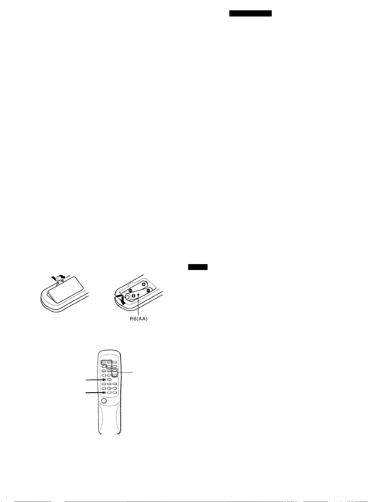
Inserting batteries -► 0
Detach the battery cover on the rear of the remote control and
insert two R6 (size AA) batteries.
ID
SHIFT
FUNCTION
c>
■ d)
When to replace the batteries
The maximum operational distance between the remote control
and the sensor in the display window should be approximately 5
meters (16 feet). When this distance decreases, replace the
batteries with new ones.
NOTE
• If the unit is not going to be used for an extended period of
time, remove the batteries to prevent possible electrolyte
leakage.
• The remote control may not operate correctly when:
- the line of sight between the remote control and the remote
sensor is exposed to intense light, such as direct sunlight.
- other remote controls are used nearby (television, etc.).
To use the SHIFT button -» 0
Buttons (D have two different functions. One of these functions
is indicated on the button, and the other on the plate above the
button.
To use the function on the button, simply press the button.
To use the function on the plate above the button, press the
button while pressing the SHIFT button.
To use the FUNCTION button 0
The FUNCTION button substitutes for the function buttons (TAPE,
TUNER, AUX/VIDEO, CD) on the main unit.
Each time the FUNCTION button is pressed, the next function is
selected cyclically.
12

PREPARATIVOS
]
"1Œ1522H33
ANTES DE LA OPERACION
Para encender la unidad
Pulse uno de los botones de función (TAPE, TUNER, AUX/
VIDEO, CD).
La reproducción del disco o de la cinta insertada empezará o se
recibirá la emisora previamente sintonizada (función de
reproducción directa).
También podrá utilizarse el botón POWER
• Si utiliza el cable de la batería para automóvil (CC 12 V), pulse
el botón POWER o uno de los botones de control (función
DIRECT PLAY) durante unos Instantes más para activar la
unidad.
Después de ia utilización
Pulse el botón POWER para desconectar la alimentación. La
visuallzación pasará a ser la del reloj.
Utilización de auriculares
Conecte los auriculares con clavija estéreo (3,5 mm 0) a la
minitoma PHONES.
Mientras los auriculares estén conectados no saldrá sonido por
los altavoces.
CONTROL REMOTO
Inserción de las pilas-» Q
Quite la tapa de las pilas, ubicada en la parte trasera del control
remoto, e inserte dos pilas R6 (tamaño AA).
Cuándo reemplazar las pilas
La distancia máxima de operación entre el control remoto y el
sensor de señales del control remoto en el visualizador deberá
ser de 5 metros aproximadamente. Cuando disminuya esta
distancia, reemplace las pilas por otras nuevas.
AVANT L’UTILISATION
Pour mettre l’appareil sous tension
Appuyer sur une des touches de fonction (TAPE, TUNER, AUX/
VIDEO, CD).
La lecture du disque ou de la cassette en place commence, ou
la station écoutée en dernier est reçue (fonction de lecture
directe).
On peut aussi appuyer sur la touche POWER.
• Lorsque l’appareil est alimenté sur une prise d’allume-cigare
(12 V CC). appuyez un peu plus longtemps sur la touche
POWER ou sur l’une des touches de fonction (fonction DIRECT
PLAY) pour allumer l’appareil
Après l’utilisation
Appuyer sur la touche POWER pour couper l’alimentation.
L’affichage passe à l’horloge.
Utilisation d’un casque
Brancher un casque muni d’une fiche stéréo (3,5 mm 0) sur la
miniprise PHONES.
Aucun son ne sort par les enceintes quand un casque est
branché.
TELECOMMANDE
Mise en piace des piies-» 0
Enlever le couvercle des piles du dos de la télécommande et
mettre deux piles R6 (taille AA) en piace.
Quand remplacer ies piies
La distance maximale de fonctionnement de la télécommande
entre cette dernière et le capteur situé sur la fenêtre d’affichage
doit être d’environ cinq mètres. Lorsque cette distance diminue,
remplacer les piles par des neuves.
• Si la unidad no va a ser utilizada durante mucho tiempo, quite
las pilas para evitar las posibles fugas de electrólito.
• El control remoto quizá no funcione correctamente cuando:
- la línea de visión entre el control remoto y el sensor de señales
del control remoto está expuesta a una luz intensa como, por
ejemplo, la luz del sol.
- otros controles remotos (televisores, etc.) estén siendo
utilizados cerca de esta unidad.
Para utilizar ei botón SHIFT -» Q]
Los botones © poseen dos funciones diferentes. Una de estas
funciones está indicada en el botón, y la otra en la placa situada
sobre el botón.
Para utilizar la función del botón, pulse simplemente el botón.
Para usar la función de la placa situada sobre el botón, pulse el
botón manteniendo presionado el botón SHIFT.
Para utilizar ei botón FUNCTION -► B
El botón FUNCTION substituye la función de ios botones (TAPE,
TUNER, AUX/VIDEO, y CD) de ia unidad principal.
Cada vez que presione el botón FUNCTION, la función siguiente
se seleccionará cíclicamente.
• Si la télécommande ne doit pas être utilisée pendant longtemps,
enlever les piles pour éviter tout risque de fuite d’électrolyte.
• La télécommande risque de ne pas fonctionner correctement
quand:
- l’espace entre la télécommande et le capteur est exposé à
une lumière intense, comme le soleil.
- d’autres télécommandes (téléviseur, etc.) sont utilisées à
proximité.
Pour utiliser la touche SHIFT -► 0
Les touches ® ont deux fonctions différentes. Une des fonctions
est indiquée sur la touche et l’autre sur la plaque au-dessus de
la touche.
Pour utiliser la fonction indiquée sur la touche, appuyer
simplement sur la touche.
Pour utiliser la fonction indiquée sur la plaque au-dessus de la
touche, appuyer sur la touche tout en tenant la touche SHIFT
enfoncée.
Pour utiliser ia touche FUNCTION -» B
La touche FUNCTION remplace les touches de fonction (TAPE,
TUNER, AUX/VIDEO, CD) sur l’appareil principal.
A chaque pression sur la touche FUNCTION, ia fonction suivante
est sélectionnée cycliquement.
13
■ Cl OCK
PREPARATIONS
1
SEniNG THE CLOCK
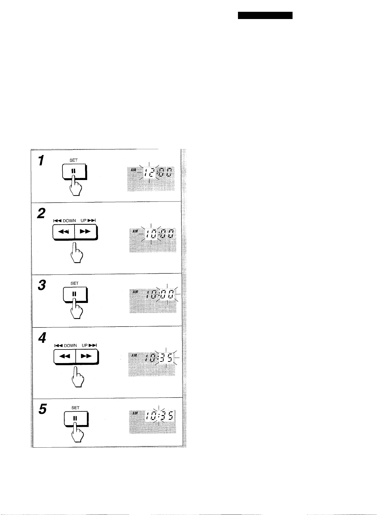
When the AC cord is just connected, the clock display flashes.
Set the time as follows while the power is off.
1,3,5
2,4
CP
@
□□aa
P“
SHIFT
1 Press the II SET button.
The hour flashes.
2 Press the DOWN or UP button to
designate the hour.
3 Press the II SET button to set the hour.
The hour stops flashing and the minute starts flashing.
4 Press the DOWN or UP button to
designate the minute.
5 Press the II SET button to set the minute and
complete setting.
The minute stops flashing on the display and the clock starts
from 00 second.
To correct the current time
Press the POWER button to turn the unit off. Press the II SET
button, the clock display flashes and carry out steps 1 to 5 above.
To display the current time
Press the CLOCK button while pressing the SHIFT button on
the remote control. The clock is displayed for 4 seconds.
However, the time cannot be displayed during recording.
To switch to the 24-hour standard
Press the CLOCK button while pressing the SHIFT button on
the remote control and then press the ■ button within 4 seconds.
Repeat the same procedure to restore the 12-hour standard.
If the clock display flashes while the power is off
This is caused by a power interruption. The current time needs
to be reset.
If power is interrupted for more than approximately 24 hours, all
settings stored in memory after purchase need to be reset.
14
 Loading...