


Aiwa KSM-880CAB, AZG-1 Z8RDC1, AZG-1 Z8RDC, AZG-1 YZ8RDM, AZG-1 Z8RDM Service Manual
...AZG-1 English
SERVICE MANUAL
CD MECHANISM |
BASIC CD MECHANISM:KSM-880CAB |
|
|
TYPE
Z8RDLC
YZ8RDLM
Z8RDLM
Z8RDLC1
Z8RDM
YZ8RDM
Z8RDC
Z8RDC1
S/M Code No. 09-001-335-3N4
DATA
PROTECTION OF EYES FROM LASER BEAM DURING SERVICING
This set employs laser. Therefore, be sure to follow carefully the instructions below when servicing.
WARNING!
WHEN SERVICING, DO NOT APPROACH THE LASER EXIT WITH THE EYE TOO CLOSELY. IN CASE IT IS NECESSARY TO CONFIRM LASER BEAM EMISSION. BE SURE TO OBSERVE FROM A DISTANCE OF MORE THAN 30cm FROM THE SURFACE OF THE OBJECTIVE LENS ON THE OPTICAL PICK-UP BLOCK.
Caution: Invisible laser radiation when open and interlocks defeated avoid exposure to beam.
Advarsel:Usynling laserståling ved åbning, når sikkerhedsafbrydere er ude af funktion. Undgå udsættelse for stråling.
VAROITUS!
Laiteen Käyttäminen muulla kuin tässä käyttöohjeessa mainitulla tavalla saattaa altistaa käyt-täjän turvallisuusluokan 1 ylittävälle näkymättömälle lasersäteilylle.
VARNING!
Om apparaten används på annat sätt än vad som specificeras i denna bruksanvising, kan användaren utsättas för osynling laserstrålning, som överskrider gränsen för laserklass 1.
CAUTION
Use of controls or adjustments or performance of procedures other than those specified herein may result in hazardous radiation exposure.
ATTENTION
L'utilisation de commandes, réglages ou procédures autres que ceux spécifiés peut entraîner une dangereuse exposition aux radiations.
ADVARSEL!
Usynlig laserståling ved åbning, når sikkerhedsafbrydereer ude af funktion. Undgå udsættelse for stråling.
This Compact Disc player is classified as a CLASS 1 LASER product.
The CLASS 1 LASER PRODUCT label is located on the rear exterior.
CLASS 1 LASER PRODUCT
KLASSE 1 LASER PRODUKT
LUOKAN 1 LASER LAITE
KLASS 1 LASER APPARAT
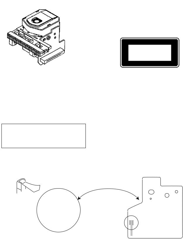
Precaution to replace Optical block
Body or clothes electrostatic potential could ruin laser diode in the optical block. Be sure ground body and workbench, and use care the clothes do not touch the diode.
1)After the connection, remove solder shown in the figure below.
Solder
2
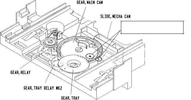
How to Adjust the Rotating Phase of the
Gear, Main Cam
1)Push down the hooking catch of the CHAS. MECH, and remove the TRAY.
2)Align the arrow mark of the Gear, Main Cam with the black round mark of the CHAS, MECHA as shown below.
3)Confirm that the Slide, Mech Cam is located in the right position, then insert the TRAY gently.
Caution: If the rotating phase of the Gear, Main Cam is incorrectly adjusted, the chucking operation and tray movement will have malfunction.
Align the arrow 2 mark with the black round • mark.
3

ELECTRICAL MAIN PARTS LIST
REF. NO |
PART NO. |
KANRI |
DESCRIPTION |
|
|
NO. |
|
IC
87-A20-446-010 C-IC,LA9241ML 87-A21-319-010 C-IC,LC78622NE 87-A20-445-010 IC,BA5936
TRANSISTOR
|
87-026-609-080 |
TR,KTA1266GR |
|
87-026-295-080 |
TR,DTC144TK |
|
87-A30-087-080 |
C-FET,2SK2158 |
|
87-026-237-080 |
CHIP-TR,DTC124XK |
|
87-A30-076-080 |
C-TR,2SC3052F |
|
87-A30-075-080 |
C-TR,2SA1235F |
DIODE |
|
|
|
87-020-465-080 |
DIODE,1SS133 (110MA) |
|
87-020-331-080 |
CHIP-DIODE,DAN202K |
|
87-A40-337-080 |
ZENER,MTZJ 6.8B |
|
87-A40-313-080 |
C-DIODE,MC 2840 |
|
87-A40-620-080 |
ZENER,MTZJ6.2A |
3CD C.B |
|
|
C11 |
87-012-393-080 |
C-CAP,S 0.22-16 R K |
C12 |
87-012-157-080 |
C-CAP,S 330P-50 CH |
C13 |
87-016-369-080 |
C-CAP,S 0.033-25 B K |
C14 |
87-A10-201-080 |
C-CAP,S0.33-16 KB |
C15 |
87-010-213-080 |
C-CAP,S 0.015-50 B |
|
|
<Z8RDC,Z8RDC1,Z8RDM,YZ8RDM> |
C16 |
87-010-992-080 |
C-CAP,S 0.047-25 B |
|
|
<Z8RDC,Z8RDC1,Z8RDM,YZ8RDM> |
C16 |
87-016-083-080 |
C-CAP,S 0.15-16 RK |
|
|
<Z8RDLM,Z8RDLC,Z8RDLC1,YZ8RDLM> |
C17 |
87-010-184-080 |
CHIP CAPACITOR 3300P(K) |
C18 |
87-A11-177-080 |
C-CAP,S 0.15-16 K B |
C19 |
87-010-992-080 |
C-CAP,S 0.047-25 B |
C20 |
87-010-178-080 |
CHIP CAP 1000P |
C21 |
87-012-393-080 |
C-CAP,S 0.22-16 R K |
C22 |
87-016-083-080 |
C-CAP,S 0.15-16 RK |
C23 |
87-010-197-080 |
CAP, CHIP 0.01 DM |
C24 |
87-010-186-080 |
CAP,CHIP 4700P |
C25 |
87-010-400-040 |
CAP,E 0.47-50 |
C26 |
87-010-322-080 |
C-CAP,S 100P-50 CH |
C27 |
87-010-382-040 |
CAP,E 22-25 SME |
C28 |
87-010-545-040 |
CAP,E 0.22-50 SME |
C29 |
87-010-184-080 |
CHIP CAPACITOR 3300P(K) |
C31 |
87-010-186-080 |
CAP,CHIP 4700P |
C32 |
87-010-315-080 |
C-CAP,S 27P-50 CH |
C33 |
87-016-081-080 |
C-CAP,S 0.1-16 RK |
C35 |
87-010-196-080 |
CHIP CAPACITOR,0.1-25 |
C37 |
87-010-405-080 |
CAP, ELECT 10-50V |
C38 |
87-010-263-080 |
CAP, ELECT 100-10V |
C39 |
87-010-197-080 |
CAP, CHIP 0.01 DM |
C40 |
87-010-401-080 |
CAP, ELECT 1-50V |
C41 |
87-016-081-080 |
C-CAP,S 0.1-16 RK |
C42 |
87-010-263-080 |
CAP, ELECT 100-10V |
C43 |
87-010-197-080 |
CAP, CHIP 0.01 DM |
C44 |
87-010-263-080 |
CAP, ELECT 100-10V |
C46 |
87-010-196-080 |
CHIP CAPACITOR,0.1-25 |
C47 |
87-010-260-080 |
CAP, ELECT 47-25V |
C48 |
87-010-196-080 |
CHIP CAPACITOR,0.1-25 |
C49 |
87-010-404-080 |
CAP, ELECT 4.7-50V |
C50 |
87-010-197-080 |
CAP, CHIP 0.01 DM |
C51 |
87-010-263-040 |
CAP,E 100-10 |
C52 |
87-012-156-080 |
C-CAP,S 220P-50 CH |
C71 |
87-012-393-080 |
C-CAP,S 0.22-16 R K |
C101 |
87-016-369-080 |
C-CAP,S 0.033-25 B K |
C102 |
87-016-081-080 |
C-CAP,S 0.1-16 RK |
C103 |
87-010-318-080 |
C-CAP,S 47P-50 CH |
REF. NO |
PART NO. |
KANRI |
DESCRIPTION |
|
|
|
|
NO. |
|
C104 |
87-012-154-080 |
C-CAP,S 150P-50 CH |
||
C105 |
87-010-196-080 |
CHIP CAPACITOR,0.1-25 |
||
C109 |
87-010-197-080 |
CAP, CHIP 0.01 DM |
||
C111 |
87-010-312-080 |
C-CAP,S 15P-50 CH |
||
C112 |
87-010-154-080 |
CAP CHIP 10P |
||
C113 |
87-010-178-080 |
CHIP CAP 1000P |
||
C115 |
87-010-404-080 |
CAP, ELECT 4.7-50V |
||
C116 |
87-010-196-080 |
CHIP CAPACITOR,0.1-25 |
||
C117 |
87-010-263-040 |
CAP,E 100-10 |
||
C118 |
87-010-178-080 |
CHIP CAP 1000P |
||
C121 |
87-010-403-080 |
CAP, ELECT 3.3-50V |
||
C122 |
87-010-403-080 |
CAP, ELECT 3.3-50V |
||
C123 |
87-010-180-080 |
C-CER 1500P |
||
C124 |
87-010-180-080 |
C-CER 1500P |
||
C132 |
87-010-196-080 |
CHIP CAPACITOR,0.1-25 |
||
C135 |
87-010-314-080 |
C-CAP,S 22P-50V |
||
C191 |
87-010-263-040 |
CAP,E 100-10 |
||
C192 |
87-010-178-080 |
CHIP CAP 1000P |
||
C192 |
87-010-178-080 |
CHIP CAP 1000P |
||
C193 |
87-010-196-080 |
CHIP CAPACITOR,0.1-25 |
||
C201 |
87-010-196-080 |
CHIP CAPACITOR,0.1-25 |
||
C204 |
87-010-196-080 |
CHIP CAPACITOR,0.1-25 |
||
C205 |
87-010-196-080 |
CHIP CAPACITOR,0.1-25 |
||
C206 |
87-010-196-080 |
CHIP CAPACITOR,0.1-25 |
||
C207 |
87-010-196-080 |
CHIP CAPACITOR,0.1-25 |
||
C208 |
87-010-196-080 |
CHIP CAPACITOR,0.1-25 |
||
C211 |
87-010-405-040 |
CAP,E 10-50 |
||
C212 |
87-010-405-040 |
CAP,E 10-50 |
||
C213 |
87-010-196-080 |
CHIP CAPACITOR,0.1-25 |
||
C251 |
87-010-322-080 |
C-CAP,S 100P-50 CH |
||
C252 |
87-010-322-080 |
C-CAP,S 100P-50 CH |
||
C253 |
87-010-322-080 |
C-CAP,S 100P-50 CH |
||
C281 |
87-010-382-040 |
CAP,E 22-25 SME |
||
C401 |
87-A10-730-080 |
CAP,E 1000-16 SMG |
||
C402 |
87-010-197-080 |
CAP, CHIP 0.01 DM |
||
C403 |
87-010-196-080 |
CHIP CAPACITOR,0.1-25 |
||
C404 |
87-010-260-040 |
CAP,E 47-25 SME |
||
C405 |
87-010-382-080 |
CAP, ELECT 22-25V |
||
C421 |
87-010-382-080 |
CAP, ELECT 22-25V |
||
C422 |
87-010-196-080 |
CHIP CAPACITOR,0.1-25 |
||
C901 |
87-010-260-080 |
CAP, ELECT 47-25V |
||
C902 |
87-010-196-080 |
CHIP CAPACITOR,0.1-25 |
||
CN1 |
87-A60-429-010 |
CONN,16P H TOC-A |
||
CN2 |
87-099-199-010 |
CONN,6P 6216 H |
||
CN201 |
87-099-030-010 |
CONN,13P 6216H |
||
CN203 |
87-099-212-010 |
CONN,5P 6216 V |
||
CN204 |
84-ZG1-648-010 |
CONN ASSY,6P |
||
|
|
|
|
<Z8RDLM,YZ8RDLM,Z8RDM,YZ8RDM> |
CN204 |
84-ZG1-675-010 |
CONN ASSY,6P (GETA) |
||
|
|
|
|
<Z8RDC,Z8RDC1,Z8RDLC,Z8RDLC1> |
L11 |
87-005-849-080 |
COIL,10UH(CECS) |
||
L101 |
87-005-614-080 |
COIL 100UH LAV35 J |
||
L102 |
87-005-602-080 |
COIL,10UH LAV35 J |
||
LED901 |
87-A40-558-010 |
LED,SLZ-8128A-01-A |
||
M201 |
87-045-383-010 |
MOT,M9I50T28-2 |
||
|
|
|
|
<Z8RDC,Z8RDC1,Z8RDLC,Z8RDLC1> |
M201 |
87-045-305-010 |
MOTOR, RF-500TB DC-5V (2MA) |
||
|
|
|
|
<Z8RDLM,YZ8RDLM,Z8RDM,YZ8RDM> |
SFR101 |
87-A90-787-080 |
SFR,100K H HOKU |
||
SW201 |
87-036-109-010 |
PUSH SWITCH |
||
SW202 |
87-036-109-010 |
PUSH SWITCH |
||
X101 |
87-A70-046-010 |
VIB,XTAL 16.934MHZ |
||
LED C.B |
|
|
|
|
LED301 |
87-A40-263-080 |
LED,SLH-56PCT31 GRN |
||
|
|
|
|
<Z8RDC,Z8RDC1,Z8RDM,YZ8RDM> |
LED302 |
87-A40-268-080 |
LED,SLH-56DCT31 ORN |
||
LED303 |
87-A40-268-080 |
LED,SLH-56DCT31 ORN |
||
|
|
|
|
<Z8RDC,Z8RDC1,Z8RDM,YZ8RDM> |
LED303 |
87-A40-263-080 |
LED,SLH-56PCT31 GRN |
||
|
|
|
|
<Z8RDLM,Z8RDLC,Z8RDLC1,YZ8RDLM> |
4
REF. NO |
PART NO. |
KANRI |
DESCRIPTION |
|
|
NO. |
|
LED304 |
87-A40-263-080 |
LED,SLH-56PCT31 GRN |
|
|
|
|
<Z8RDC,Z8RDC1,Z8RDM,YZ8RDM> |
T-T C.B |
|
|
|
C401 |
87-A11-148-080 |
CAP,TC U 0.1-50 Z F |
|
CON401 |
86-NFZ-675-010 |
CONN,5P H 6216-11H |
|
M401 |
87-045-364-010 |
MOTOR(BCH3B14) |
|
PS401 |
87-026-573-010 |
SNSR,PHOTO GP1S53V |
|
MOTOR C.B |
|
|
|
PIN3 |
91-564-722-110 |
CONN,PIN 6P |
|
SW1 |
91-572-085-110 |
LEAF SWITCH |
|
•Regarding connectors, they are not stocked as they are not the initial order items.
The connectors are available after they are supplied from connector manufacturers upon the order is received.
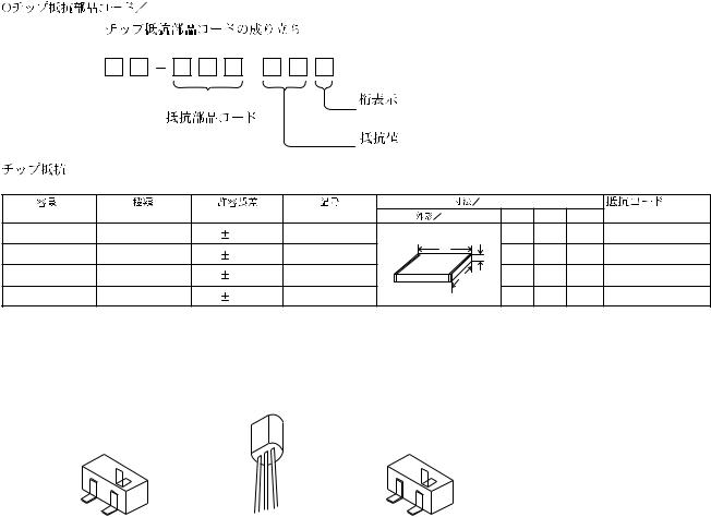
CHIP RESISTOR PART CODE
Chip Resistor Part Coding
8 8
A
Figure
Resistor Code
Value of resistor
Chip resistor
Wattage |
Type |
Tolerance |
Symbol |
Dimensions (mm) |
|
: A |
||
Form |
L |
W |
t |
Resistor Code : A |
||||
1/16W |
1005 |
5% |
CJ |
|
1.0 |
0.5 |
0.35 |
104 |
1/16W |
1608 |
5% |
CJ |
L |
1.6 |
0.8 |
0.45 |
108 |
t |
||||||||
1/10W |
2125 |
5% |
CJ |
W |
2 |
1.25 |
0.45 |
118 |
1/8W |
3216 |
5% |
CJ |
|
3.2 |
1.6 |
0.55 |
128 |
TRANSISTOR ILLUSTRATION
C |
|
D |
B |
|
G |
E |
E C B |
S |
2SA1235F |
KTA1266GR |
2SK2158 |
2SC3052F |
|
|
DTC124XK |
|
|
DTC144TK |
|
|
5

WAVE FORM |
|
|
|
1 IC11 Pin = (RFSH) |
VOLT/DIV: 0.5V |
4 IC11 Pin ³ (SPD) |
VOLT/DIV: 100mV |
|
TIME/DIV: 1µS |
|
TIME/DIV: 1mS |
|
MAX |
|
|
|
2.0±0.1 Vp-p |
|
VREF |
|
0 V |
|
|
|
|
|
|
EYE PATTERN |
|
|
|
must be CLEAR and MAX |
|
|
|
2 |
IC11 Pin ^ (FD) |
VOLT/DIV: 100mV |
5 |
|
|
TIME/DIV: 1mS |
|
|
|
VREF |
|
3 |
IC11 Pin % (TO) |
VOLT/DIV: 100mV |
|
|
|
TIME/DIV: 1mS |
|
VREF |
IC BLOCK DIAGRAM
IC, BA5936S
IC11 Pin ª (SLD) |
VOLT/DIV: 200mV |
|
TIME/DIV: 2S |
|
VREF |
6
 Loading...