


DVD STEREO SYSTEM
SISTEMA ESTEREO DVD
CHAINE STEREO AVEC LECTEUR DE DVD
HT-DV90
OPERATING INSTRUCTIONS
MANUAL DE INSTRUCCIONES
MODE D’EMPLOI
En (English)
For assistance and information
call toll free 1-800-BUY-AIWA
(United States and Puerto Rico)
E (Español)
F (Français)
8B-AX2-903-11
011201BCK-U-AN
U
ENGLISH
WARNING
TO REDUCE THE RISK OF FIRE OR ELECTRIC
SHOCK, DO NOT EXPOSE THIS APPLIANCE TO
RAIN OR MOISTURE.
CAUTION
RISK OF ELECTRIC SHOCK
DO NOT OPEN
“CAUTION:TO REDUCE THE RISK OF
ELECTRIC SHOCK,
DO NOT REMOVE COVER (OR BACK).
NO USER-SERVICEABLE PARTS INSIDE.
REFER SERVICING TO QUALIFIED
SERVICE PERSONNEL.”
Explanation of Graphical Symbols:
The lightning flash with arrowhead symbol,
within an equilateral triangle, is intended to
alert the user to the presence of uninsulated
“dangerous voltage” within the product’ s
enclosure that may be of suf ficient magnitude
to constitute a risk of electric shock to persons.
The exclamation point within an equilateral
triangle is intended to alert the user to the
presence of important operating and
maintenance (servicing) instructions in the
literature accompanying the appliance.
PRECAUTIONS
Read the Operating Instructions carefully and completely before
operating the unit. Be sure to keep the Operating Instructions for
future reference. All warnings and cautions in the Operating
Instructions and on the unit should be strictly followed, as well
as the safety suggestions below .
Warning
To prevent electric shock or injury , these safety instructions should
be followed in the installation, use and servicing the unit.
Installation
Attachments - Do not use attachments not recommended by
the unit manufacturer as they may result in the risk of fire, electric
shock or injury to persons.
Water and Moisture - Do not use this unit near water - for
example, near a bathtub, washbowl, kitchen sink, or laundry tub,
in a wet basement, or near a swimming pool, and the like.
Heat - Do not use this unit near sources of heat, including heating
vents, stoves, or other appliances that generate heat. It also
should not be placed in temperatures less than 5˚C (41˚F) or
greater than 35˚C (95˚F ).
Mounting surface - Place the unit on a flat, even surface.
Accessories - Do not place this unit on an unstable cart, stand,
tripod, bracket, or table. The unit may fall, causing serious injury
to a child or an adult, and serious damage to the appliance. Use
only with a cart, stand, tripod, bracket, or table recommended by
the manufacturer , or sold with the unit. Any mounting of the
appliance should follow the manufacturer ’s instructions, and
should use a mounting accessory recommended by the
manufacturer .
Owner’s record
For your convenience, record the model number and serial
number (you will find them on the rear of your set) in the space
provided below . Please refer to them when you contact your Aiwa
dealer in case of dif ficulty .
Model No. Serial No. (Lot No.)
HT-DV90
SX-F90
SX-R90
SX-C90
TS-W90
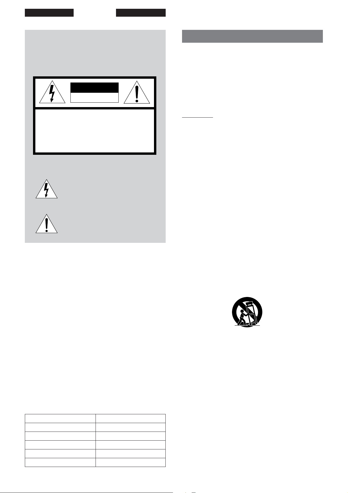
Portable cart - An appliance and cart combination should be
moved with care. Quick stops, excessive force, and uneven
surfaces may cause the appliance and cart combination to
overturn.
PORTABLE CART WARNING
S3125A
Ventilation - The unit should be situated with adequate space
around it so that proper heat ventilation is assured. Allow 10 cm
clearance from the rear and the top of the unit, and 5 cm from
the each side.
Slots and openings in the cabinet and the back or bottom are
provided for ventilation, and to ensure reliable operation of the
unit and to protect it from overheating, these openings must not
be blocked or covered. The openings should never be blocked
by placing the unit on a bed, sofa, rug or other similar surface.
(This unit should never by placed near or over a radiator or heat
register .) This unit should not be placed in a built-in installation
such as a bookcase unless proper ventilation is provided.
Object and Liquid Entry - Never push objects of any kind into
this unit through the cabinet slots as they may touch dangerous
voltage points or short-circuit parts that could result in a fire or
electric shock. Never spill liquid of any kind on the unit.
2
ENGLISH
Electric Power
Power Sources - This unit should be operated only from the
type of power source indicated on the marking label. If you are
not sure of the type of power supply to your home, consult your
appliance dealer or local power company . To operate unit on
battery power , or other sources, refer to the operating instructions.
Grounding or Polarization - This unit is provided with a polarized
alternating-current line plug (a plug having one blade wider than
the other). This plug will fit into the power outlet only one way .
This is a safety feature. If you are unable to insert the plug fully
into the outlet, try reversing the plug. If the plug should still fail to
fit, contact your electrician to replace your obsolete outlet. Do
not defeat the safety purpose of the polarized plug.
Power-Cord Protection - This unit is provided with an attachment
plug having overload protection. This is a safety feature. See
operating instructions for replacement or resetting of protective
device. If replacement of the plug is required, be sure the service
technician has used a replacement plug specified by the
manufacturer that has the same overload protection as the
original plug.
Overloading - Do not allow anything to rest on the power cord.
Do not overload wall outlets and extension cords as this can
result in fire or electric shock. Do not locate this unit where the
cord will be abused by persons walking on it.
Outdoor Antenna
Power lines - An outside antenna system should not be located
in the vicinity of overhead power lines or other electric light or
power circuits, or where it can fall into such power lines or circuits.
When installing an outside antenna system, extreme care should
be taken to keep from touching such power lines or circuits as
contact with them might be fatal.
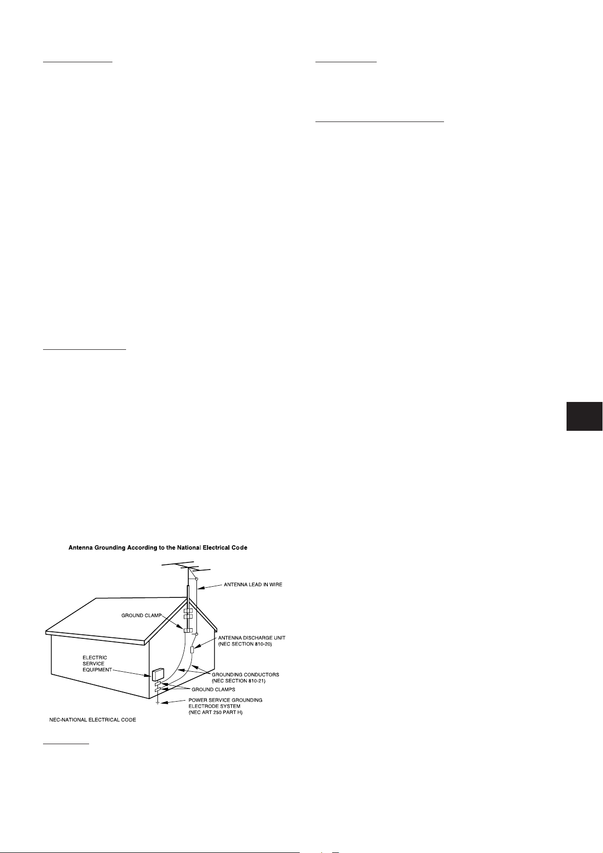
Outdoor Antenna Grounding - If an outside antenna or cable
system is connected to the unit, be sure the antenna or cable
system is grounded so as to provide some protection against
voltage surges and built-up static charges. Section 810 of the
National Electrical Code, ANSI/NFPA No.70, provides information
with regard to proper grounding of the mast and supporting
structure, grounding of the lead-in wire to an antenna discharge
unit, size of grounding conductors, location of antenna-discharge
unit, connection to grounding electrodes, and requirements for
the grounding electrode. See the figure.
Maintenance
Cleaning - Unplug this unit from the wall outlet before cleaning.
Do not use liquid cleaners or aerosol cleaners. Use a damp cloth
for cleaning.
Damage Requiring Service
Unplug this unit from the wall outlet and refer servicing to qualified
service personnel under the following conditions:
1) When the power cord or plug is damaged or frayed.
2) If the liquid has been spilled into the unit.
3) If the unit has been exposed to rain or water.
4) If the unit does not operate normally by following the
operating instructions. Adjust only those controls that
are covered by the operating instructions as improper
adjustment of other controls may result in damage and
will often require extensive work by a qualified
technician to restore the unit to normal operation.
5) If the unit has been dropped or the cabinet has been
damaged.
6) When the unit exhibits a distinct change in performance
- this indicates a need for service.
Do not attempt to service this unit yourself as opening or removing
covers may expose you to dangerous voltage or other hazards.
Refer all servicing to qualified service personnel.
Replacement Parts - When replacement parts are required, be
sure the service technician has used replacement parts specified
by the manufacturer or having the same characteristics as the
original part. Unauthorized substitutions may result in fire, electric
shock or other hazards.
Safety Check - Upon the completion of any service or repairs to
this unit, ask the service technician to perform safety checks to
determine that the unit is in proper operating condition.
En
Lightning
For added protection for this unit receiver during a lightning storm,
or when it is left unattended and unused for long periods of time,
unplug it from the wall outlet and disconnect the antenna or cable
system. This will prevent damage to the unit due to lightning and
powerline surges.
ENGLISH
3
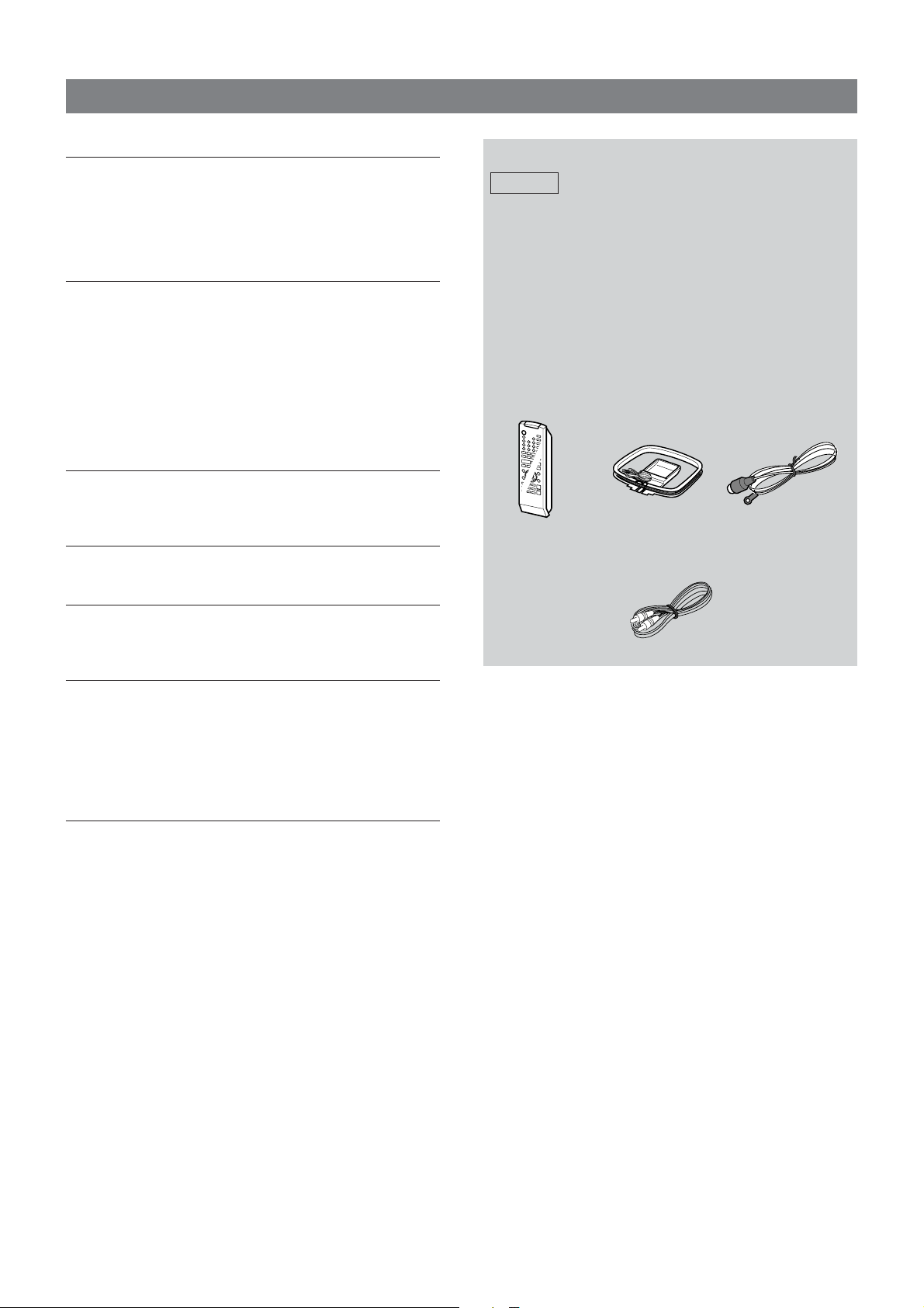
TABLE OF CONTENTS
PREPARATIONS
CONNECTIONS .................................................................. 5
CONNECTING OTHER EQUIPMENT ................................ 7
REMOTE CONTROL ........................................................... 9
PARTS AND CONTROLS ................................................... 9
BEFORE OPERATION...................................................... 12
PLAYING DVDS AND AUDIO CDS
BEFORE USE.................................................................... 13
BASIC OPERATIONS ....................................................... 15
SELECTING A TRACK ..................................................... 17
FRAME ADVANCE AND SLOW PLAYBACK .................. 18
REPEAT PLAYBACK ........................................................ 18
PROGRAMED PLA YBACK............................................... 19
RANDOM PLA YBACK ...................................................... 20
SPECIAL DVD FEATURES............................................... 21
ON SCREEN DISPLAY INFORMATION........................... 23
SURROUND PLA YBACK
PLA YING WITH SURROUND SOUND ............................. 24
SPEAKER SETTING......................................................... 25
RADIO RECEPTION
RADIO RECEPTION ......................................................... 27
SOUND AND TIMER ADJUSTMENTS
SOUND ADJUSTMENTS.................................................. 28
SLEEP TIMER ................................................................... 29
Check your system and accessories
HT-DV90
HT-DV90 DVD stereo receiver
SX-F90 Front speakers
SX-R90 Surround speakers
SX-C90 Center speaker
TS-W90 Subwoofer
Front speaker cord (approx. 4m/13 ft.) x 2
Surround speaker cord (approx. 8m/26 ft.) x 2
Center speaker cord (approx. 3m/10 ft.) x 1
Subwoofer cord (approx. 5m/16 ft.) x 1
Remote control
Video connecting cord
FM antennaAM antenna
CUSTOMIZING DVD SETUP
OVERVIEW OF THE SETUP MENU ................................. 29
BASIC MENU OPERA TIONS ........................................... 30
RATING.............................................................................. 30
PASSWORD ...................................................................... 30
TV DISPLA Y ...................................................................... 31
TV TYPE ............................................................................ 31
GENERAL
CARE AND MAINTENANCE ............................................ 32
TROUBLESHOOTING GUIDE .......................................... 33
SPECIFICATIONS............................................................. 34
4
ENGLISH
PREPARATIONS
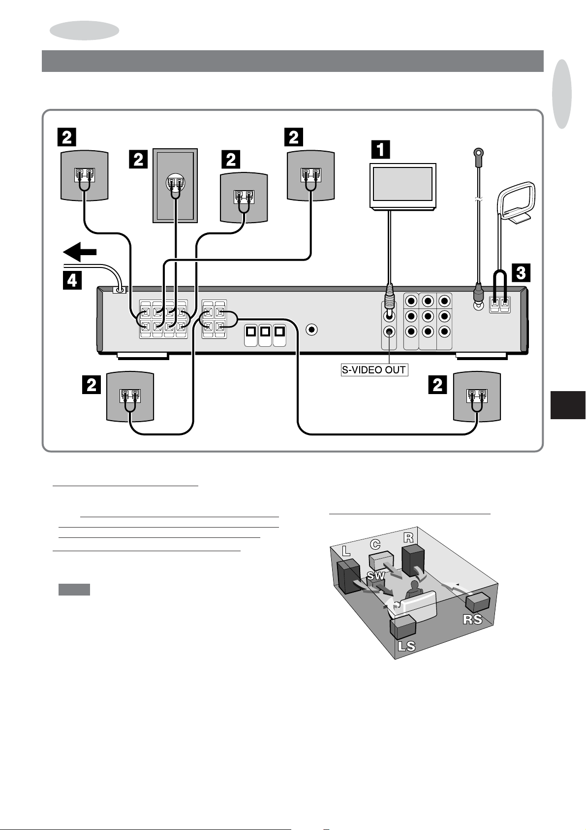
CONNECTIONS
IMPORTANT
Connect the speakers, antennas, and all optional equipment first. Then connect the AC cord.
Surround
speaker
Subwoofer
PREPARATIONS
Surround
speaker
Center speaker
En
Front speaker
1 Connect your television set to this unit.
If your TV has an S-video input jack;
Connect the S-VIDEO OUT jack of this unit to the S-video
input jack of your TV with an optional S-video connecting
Also connect the VIDEO OUT jack of this unit to the
cord.
video input jack of your TV since the signal from S-VIDEO
OUT jack is output only when the function is DVD/CD.
If your TV does not have an S-video input jack;
Connect the VIDEO OUT jack of this unit to the video input
jack of your TV with the supplied video connecting cord.
NOTE
• The illustration here shows the connection to the VIDEO
jack. S-(separate) video connection, if available, of fers
higher quality than conventional video (composite)
connection.
• If your television is a 16:9 (wide) ratio set, the default “TV
DISPLAY” setting has to be changed in the DVD setup.
See “TV DISPLAY”, page 31.
• Direct connection between this unit and your TV set is
recommended, as described above. If the video signal from
this unit is made to pass through any other video
equipment, the picture will be blurred when playing copyprotected DVDs.
•To view the video output from this unit, select the
corresponding video input on your TV .
Front speaker
2 Connect the speakers to this unit.
All speakers for a full 5.1-channel home theater configuration
come supplied with your DVD system.
Place the speakers in their proper position.
1
Speaker
placement
The front and the surround speakers appear identical but
should be dif ferentiated. Check their rear panels.
Either of the two front speakers can be used as the right or
the left one, and likewise for the surround speakers.
ENGLISH
5
• L&R: Front speakers
• C: Center speaker
Place it in the center of the two front speakers, possibly
on or below the TV set.
• LS&RS: Surround speakers
Place them directly to the side of or slightly behind the
listening area. Align them horizontally , preferably 0.6 to 1
meter above ear height.
•SW: Subwoofer
Place it anywhere between the two front speakers.
NOTE
•Do not place the left and right front speakers close to the
TV set, as doing so may cause picture noise.
• Sound output from the center and surround speakers is
only available when the surround ef fect (Dolby Surround
or DTS Surround etc.,) is activated with the appropriate
setting.
•To mount the front and surround speakers on the wall, see
“MOUNTING THE FRONT AND SURROUND
SPEAKERS”, page 8.
Connect the speakers.
2
• The black-colored cord goes to the 9 terminals and the
other cord goes to the 0 terminals.
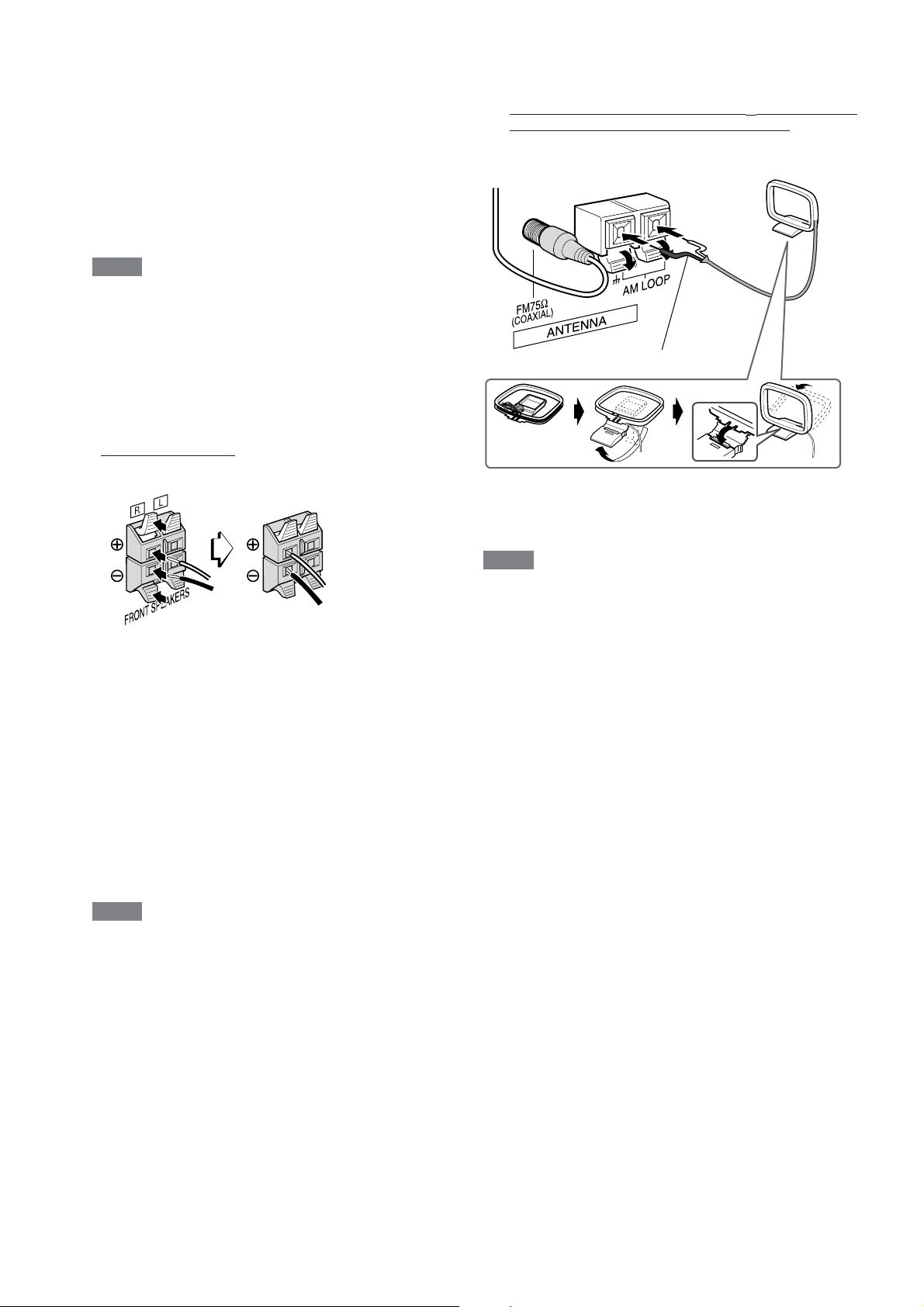
3 Connect the supplied antennas.
Connect the FM antenna to the FM 75 Ω (COAXIAL) jack
and the AM antenna to the AM LOOP terminal.
FM antenna
AM antenna
The black-colored cord goes to the 2 terminal.
4 Connect the power supply.
Plug in the AC power cord of this unit to a wall outlet.
Connecting
the speaker
cord to the
terminals
• Connect the cords to the corresponding speakers. Hold
down the lever to insert the cord, then release.
• Connect the cord from the right front speaker to the
FRONT SPEAKERS R terminals, and the cord from the
left front speaker to the FRONT SPEAKERS L terminals.
• Connect the cord from the right surround speaker to the
SURROUND SPEAKERS RS terminals, and the cord
from the left surround speaker to the SURROUND
SPEAKERS LS terminals.
• Connect the cord from the center speaker to the CENTER
SPEAKER terminals.
• Connect the cord from the subwoofer to the SUB
WOOFER terminals.
NOTE
• Connect the speaker cords securely to the terminals.
Improper connection may cause a short circuit.
• When connecting the speakers that are not supplied,
confirm the speaker impedance and the speaker setting of
this unit (page 25).
NOTE
• Do not leave objects generating magnetism, such as credit
cards, near the speakers, as the objects may be damaged.
• Do not bring the FM antenna near metal objects or curtain rails.
• Do not bring the AM antenna near other optional equipment,
the stereo system itself, the AC cord or speaker cords, since
noise will be picked up.
• Do not unwind the AM antenna wire.
6
ENGLISH
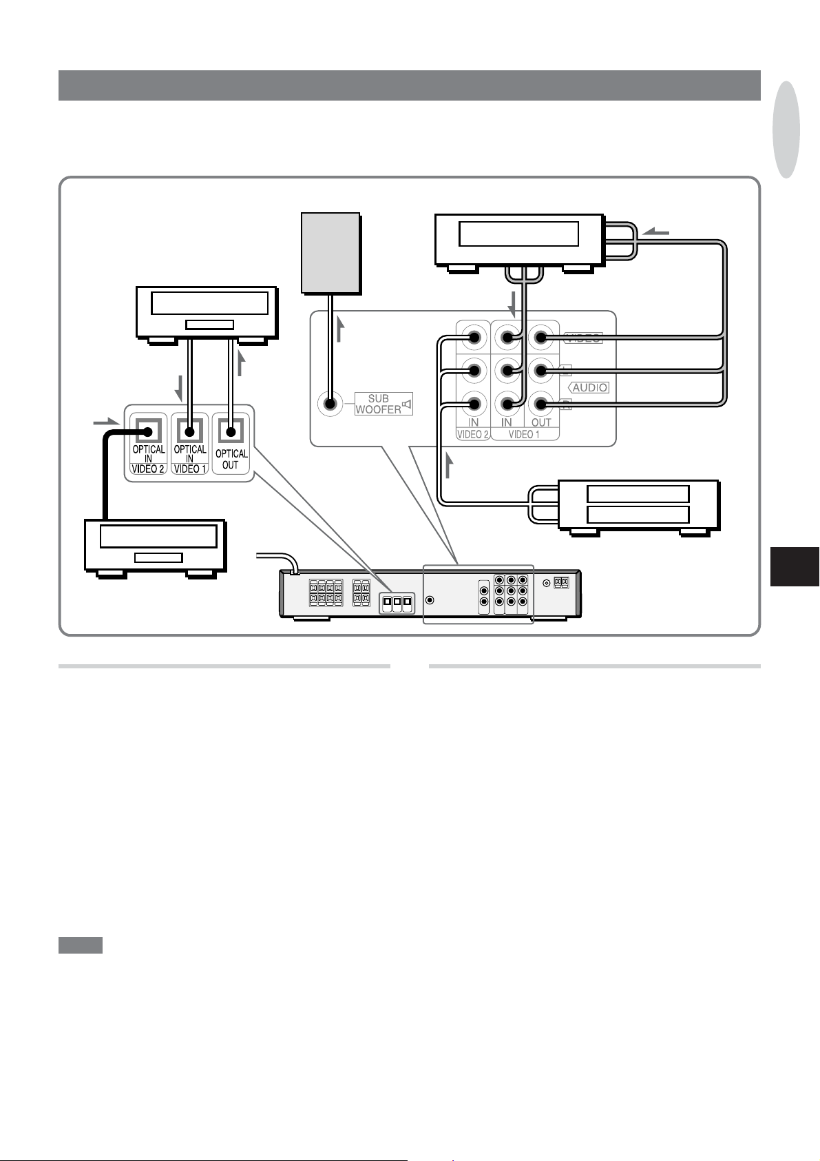
CONNECTING OTHER EQUIPMENT
Besides the basic connections described earlier , other equipment can be connected to this unit as needed.
Before making additional connections, be sure to turn of f the power and disconnect power supply for this unit and other equipment.
Wall mounting of the speakers is also described here.
MD recorder, etc.
to OPTICAL OUT jack
to OPTICAL OUT jack
MD player, etc.
to OPTICAL
IN jack
Active
subwoofer
PREPARATIONS
Video player/recorder, etc.
to LINE IN jack
to LINE OUT jack
Video player, etc.
to LINE OUT jack
En
AUDIO VIDEO 1 and VIDEO VIDEO 1 jacks
These jacks output and accept video and analog audio signals
to and from the connected equipment.
Connect audio-visual equipment such as a video recorder to
these jacks, using two optional audio-visual connecting cables
with RCA plugs.
• Connect the line output jacks of the equipment to the VIDEO 1
input jacks ( AUDIO VIDEO 1 IN L, AUDIO VIDEO 1 IN R, and
VIDEO VIDEO 1 IN) of this unit.
• Connect the line input jacks of the equipment to the VIDEO 1
output jacks ( AUDIO VIDEO 1 OUT L, AUDIO VIDEO 1 OUT
R, and VIDEO VIDEO 1 OUT) of this unit.
• Be sure to connect properly according to the color-coding;
AUDIO L: white plugs and jacks
AUDIO R: red plugs and jacks
VIDEO: yellow plugs and jacks
NOTE
•When playing/recording the source through the equipment
connected to the AUDIO VIDEO 1 OUT jacks, set the surround
playback mode to STEREO (page 24).
• The sound selected on this unit’ s function is output from VIDEO
1 OUT jacks.
• The video is output from the VIDEO 1 OUT jack only when the
function is VIDEO 2.
• When recording Dolby Digital source through the equipment
connected to the AUDIO VIDEO 1 OUT jacks, dynamic range
can be adjusted (page 29).
AUDIO VIDEO 2 and VIDEO VIDEO 2 jacks
These jacks accept video and analog audio input signals from
the connected equipment.
Connect audio-visual playback equipment, such as a video player
to these jacks, using an optional audio-visual connecting cable
with RCA plugs.
• Connect the line output jacks of the equipment to the VIDEO 2
jacks ( AUDIO VIDEO 2 IN L, AUDIO VIDEO 2 IN R, and VIDEO
VIDEO 2 IN) of this unit.
• Be sure to connect properly according to the color-coding;
AUDIO L: white plugs and jacks
AUDIO R: red plugs and jacks
VIDEO: yellow plugs and jacks
ENGLISH
7
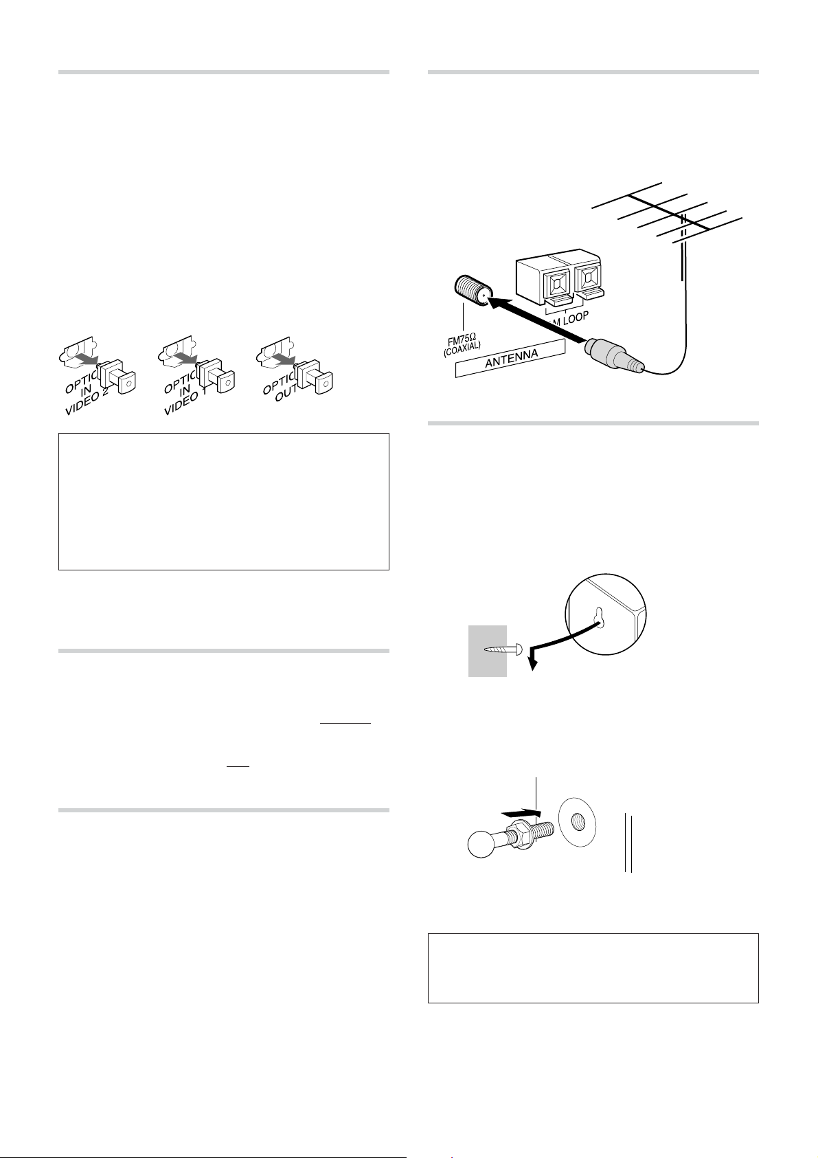
OPTICAL IN VIDEO 1/OPTICAL IN VIDEO 2
jack / OPTICAL OUT jack
The OPTICAL IN VIDEO 1 jack and OPTICAL IN VIDEO 2 jack
accept digital audio input from connected equipment.
The OPTICAL OUT jack outputs digital audio signals to the
connected equipment.
Connect digital audio playback/recording equipment, such as an
MD recorder , a DAT deck, or a CD-R deck, etc. with optional
optical fiber cables.
Connect the optical input jack of the connected equipment to the
OPTICAL OUT jack, and the optical output jack of the equipment
to the OPTICAL IN VIDEO 1 jack or the OPTICAL IN VIDEO 2
jack.
Before connecting the cable, remove the dust cap from the jacks.
Reattach them when the jacks are not to be used.
CONNECTING AN OUTDOOR ANTENNA
For better FM reception, use of an optional outdoor antenna is
recommended.
Connect the outdoor antenna to FM 75 Ω (COAXIAL) jack.
CAUTION ON CONNECTING EQUIPMENT TO THE
OPTICAL OUT JACK
When connecting digital equipment without a built-in Dolby
Digital or DTS decoder , do not play back Dolby Digital or
DTS source with multichannel surround sound. When
connecting equipment that does not comform to 96 kHz
Linear PCM source, do not play back 96 kHz Linear PCM
source. It may cause a high level of noise which could harm
your ears and damage the speakers.
• The OPTICAL IN VIDEO 1 or 2 jack shares the same video
source as the VIDEO 1 or 2 jack.
SUBWOOFER jack
This jack outputs the low frequency sounds.
Your DVD system comes supplied with a passive (non-powered)
subwoofer , to be connected to the SUBWOOFER
described on page 6.
However, if you wish to connect an optional active (powered)
subwoofer , connect it to this
connecting cord with RCA plugs.
jack using an optional audio
terminals , as
PHONES jack
Connect headphones with a stereo mini plug (ø 3.5 mm,
The jack is located at the front of this unit.
5
/32 in.).
MOUNTING THE FRONT AND SURROUND
SPEAKERS
You can mount the front and/or the surround speakers,if you want
to do so.
Using wall mounting screws (not supplied)
Select a spot that will hold the weight of the speakers and carefully
mount the surround speakers so that they are firmly secured.
Using a speaker mounting kit (not supplied)
The front and surround speakers are equipped with a 5 mm
threaded insert on their back side. Use it to attach the ball shaft
of a speaker mounting kit on the market.
Refer to the instructions of the mounting kit for further information.
• No sound is output from the speakers while the headphones
are plugged in.
• When the headphones are plugged in, the Dolby Pro Logic
surround system is canceled. The Dolby Digital or the DTS
surround system automatically switches to the 2ch STEREO
mode.
8
ENGLISH
You can attach the speakers to the pedestal on the market with
the 5 supplies screws. Refer to the instructions of the pedestal
for further information.
AIWA disclaims any responsibility for injury to persons or
other accidents caused by not fitting the front and/or surround
speakers properly or if the place of the installation is not
suitable.
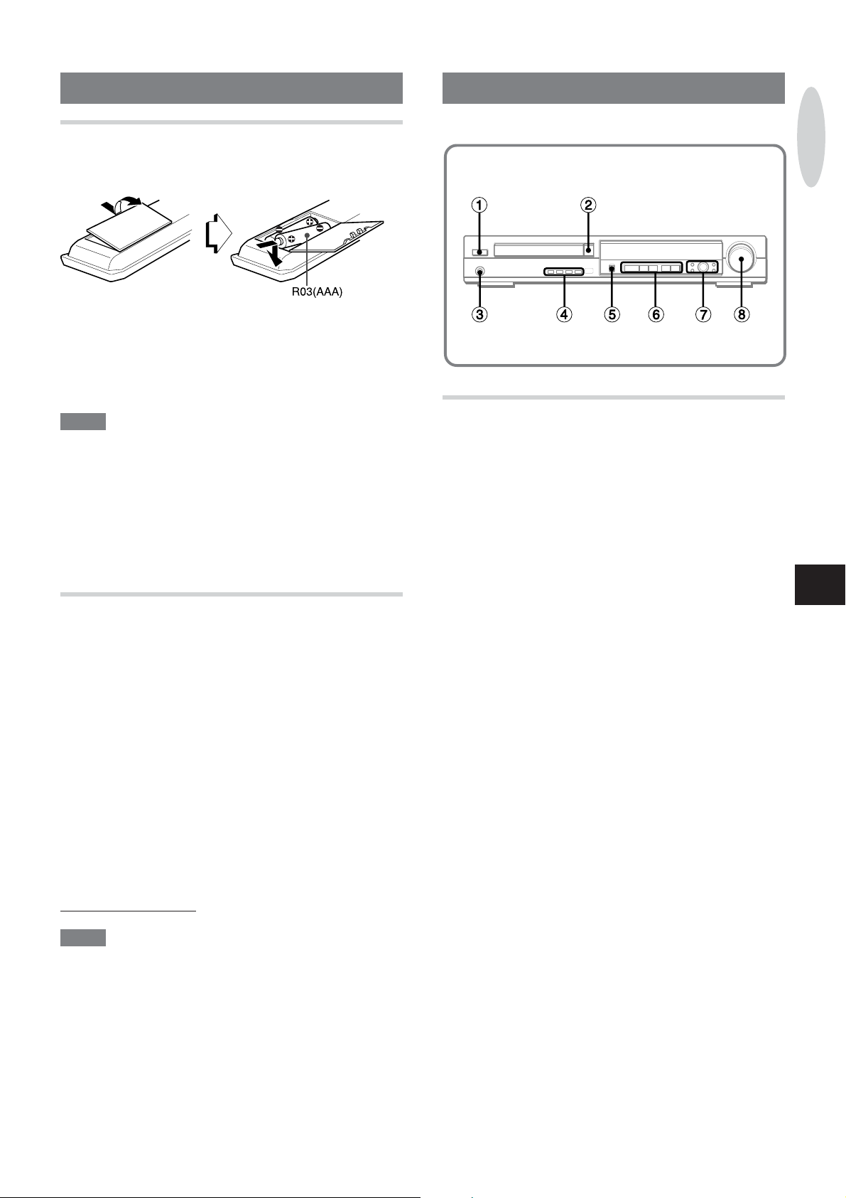
REMOTE CONTROL
INSERTING BA TTERIES
Open the battery cover on the rear and insert two R03 (size AAA)
batteries.
When to replace the batteries
The maximum operational distance between the remote control
and the sensor on the main unit should be approximately 5 meters
(16 ft.). When this distance decreases, replace the batteries with
new ones.
PARTS AND CONTROLS
PREPARATIONS
NOTE
• If the remote control is not going to be used for an extended
period of time, remove the batteries to prevent possible
electrolyte leakage.
• The remote control may not operate correctly when:
- The line of sight between the remote control and the remote
sensor inside the display window is exposed to intense light,
such as direct sunlight
- Other remote controls are used nearby (those of a television,
etc.)
OPERA TING OTHER EQUIPMENT
You can set the remote control to operate other equipment by
inputting the brand code.
Setting the brand code
1Turn on the equipment to be set.
2 Hold down the corresponding source button ( VIDEO 1, VIDEO
2, TV, CABLE/SAT.) and press 0-9 to input the three-digit
brand code. (Brand code is shown at the end of the operating
instructions.)
3 Release the corresponding source button.
The setting is completed.
Operating other equipment
Press the corresponding source button. The remote control goes
to the corresponding source mode. 0-9, TV/VIDEO, TV CH N
M, TV VOL +- and POWER etc., are available.
Pressing POWER again within 3 seconds turns this unit of f even
when the remote control is the corresponding source mode.
When operating this unit , press DVD/CD or TUNER/BAND.
NOTE
• This remote control may not correspond to all models of the
brand shown at the end of the operating instructions.
• When the batteries are removed from the remote control, all
settings stored in memory may be lost.
• Some buttons on the remote control may not work exactly .
MAIN UNIT
1 POWER 6STANDBY/ON
Turns the unit on and of f (standby).
2 zOPEN/CLOSE
Opens and closes the disc tray .
3 PHONES jack
Plug in here an optional headphones set with a stereo mini
plug (ø 3.5mm,
4 SURROUND
Selects a listening mode.
BASS/TREBLE
Adjusts the bass/treble level.
SLEEP
Enters sleep-timer setting mode.
BAND
Selects the radio band.
5 FUNCTION
Selects DVD/CD, FM (AM), VIDEO 1 (ANALOG), VIDEO 1
(DIGITAL), VIDEO 2 (ANALOG) or VIDEO 2 (DIGIT AL)
function.
6 cPRESET
Disc: starts playback.
Radio: switches between tuning mode and preset mode.
sCLEAR
Disc: stops playback.
Radio: clears a station preset.
aSET
Disc: pauses playback.
Radio: stores the received station to preset.
fr TUNING-, gt TUNING+
Disc: skips to a previous or a succeeding chapter/track when
pressed, searches a chapter/track in fast forward or fast
reverse playback when held down.
Radio:manually tunes down or up within the band (tuning
mode). Selects the preset channel (preset mode).
5
/32 in.). Speaker output is canceled.
En
ENGLISH
9
7 TOP MENU
Displays the title menu.
RETURN
Returns to the previous menu screen.
ikjl ENTER
Selects the menu item and enters the selected item.
MENU
Displays the menu for DVDs.
SETUP
Enters the setup menu for DVDs.
8 VOLUME
Adjusts the volume.
REMOTE CONTROL
Buttons with the same or similar names between the remote
control and the main unit basically serve the same function.
NOTE
When the remote control mode is VIDEO 1, VIDEO 2, TV or
CABLE/SAT., you cannot operate the main unit properly . When
operating the main unit, press DVD/CD or TUNER/BAND. When
the remote control mode is changed, the function of the main
unit is also changed.
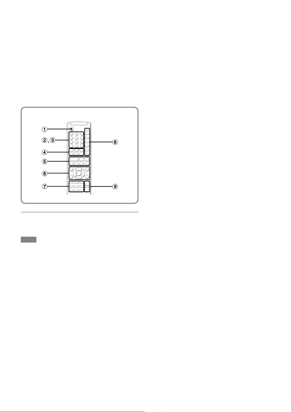
1 POWER
2 0-9
Selects a title/chapter/track of specified number .
+10
Uses this button for operating other equipment if needed.
C
Clear the program memory .
3 The numbered buttons take on these functions when pressed
together with SHIFT :
SP SETUP
Enters the speaker setting mode.
MIDNIGHT
Adjusts dynamic range (Dolby Digital software only).
ZOOM
Enlarge the picture (DVDs only).
PRGM
Enters programed playback mode (CDs only).
RANDOM
Enters random playback mode (CDs only).
REPEAT
Enters repeat playback mode.
SLEEP
MONO TU
Switches between stereo or monaural FM reception.
TITLE/CHP.
Switches the display between title and chapter .
4 VIDEO 1
Selects VIDEO 1 function and the remote control goes to
VIDEO 1 mode.
VIDEO 2
Selects VIDEO 2 function and the remote control goes to
VIDEO 2 mode.
TV
The remote control goes to TV mode.
DVD/CD
Selects DVD/CD function.
TUNER/BAND
Selects radio function and the radio band.
CABLE/SAT.
The remote control goes to cable/satellite mode.
5 cPRESET
sCLEAR
aSET
r SLOWG, t SLOWF
Plays back at slow speed (DVDs only).
f TUNING-, g TUNING+
6 TOP MENU
vRETURN
ikjlENTER
TV Ch NM(ik)
Selects TV channel.
TV Vol +-(lj)
Adjusts TV volume.
MENU
SETUP
7 SHIFT
Hold down when pressing a numbered button to change its
function to that printed above the number .
• e.g., “Press SHIFT+SP SETUP on the remote control”
means to hold down SHIFT and press 4/SP SETUP to use
the button for the speaker setting.
SURROUND
BASS/TREBLE
SUBWOOFER (+, -)
Adjusts the subwoofer level.
CENTER (+, -)
Adjusts the center level.
REAR (+, -)
Adjusts the rear (surround) level.
8 MUTE
Mutes the sound.
10
ENGLISH
ANGLE
Selects the angle to view the scene (DVDs only).
AUDIO
Changes audio tracks (DVDs only).
SUBTITLE
Changes the subtitle language (DVDs only).
ON SCREEN
Displays the disc playback status on the TV screen.
TV/VIDEO
Switches between TV or VIDEO.
DIGITAL/ANALOG
When the function is VIDEO 1 or VIDEO 2, selects digital or
analog input.
9 VOLUME +-
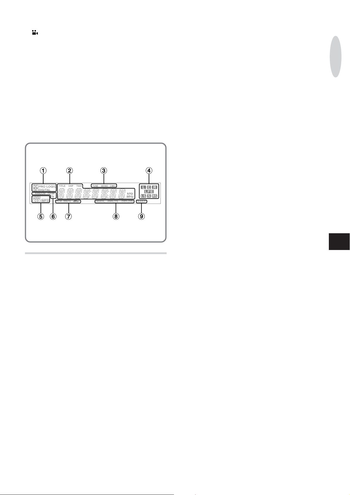
7 Audio signal type indicators
Indicates the signal type of the current audio track.
“PCM” lights up when playing back linear PCM audio signal.
(MPEG audio signal is converted to linear PCM audio signal.)
“96 kHz” indicates the sampling frequency of linear PCM audio
signal.
“dts” lights up when playing back dts (Digital Theater System)
audio signal.
8 Input type indicators
When the function is VIDEO 1 or VIDEO 2, “DIGIT AL” or
“ANALOG” lights up according to the type of audio input.
“OVER LEVEL” lights up when external analog input level is
too high.
9 SLEEP indicator
Lights up when the sleep function is active.
PREPARATIONS
DISPLA Y WINDOW
1 Surround playback mode indicators
Indicates the surround output type in which the source actually
being played.
2 Main display
Shows general information such as the active function, current
adjustment mode, title/chapter/track number , elapsed time or
radio frequency
3 TUNE/MONO/1 indicators
“TUNE” lights up during radio reception.
MONO/1 indicates the type of radio reception.
4 Active channel indicators
Lights up to show each speaker channel.
•L (Left front)
•C (Center)
•R (Right front)
• LFE (Subwoofer)
• LS (Left surround)
• S (lights up when rear channel is monaural)
• RS (Right surround)
5 Disc type indicators
Indicates the type of current disc (DVD, CD or MP3).
6 Playback mode indicators
Lights up to show the random, programed and repeat playback
modes.
En
ENGLISH
11
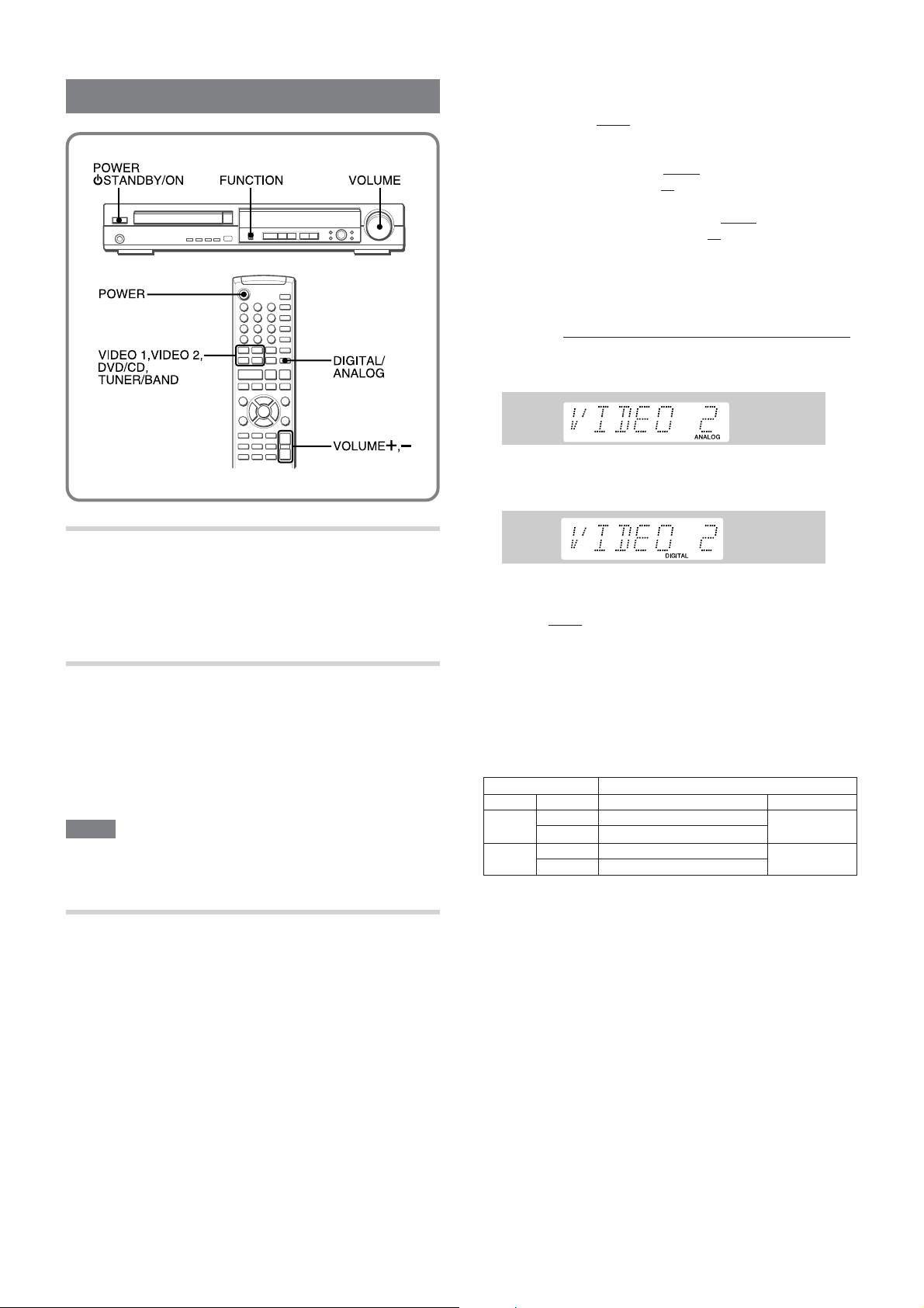
BEFORE OPERATION
When VIDEO 1 or VIDEO 2 is selected with the remote
control
The active external
the VIDEO 1 or VIDEO 2 function button and the DIGITAL/
ANALOG button on the remote control.
• Pressing VIDEO 1 selects
jack (digital audio input)
(analog audio input).
• Similarly , pressing VIDEO 2 selects
VIDEO 2 jack (digital audio input)
jacks (analog audio input).
• Pressing DIGITAL/ANALOG switches alternately between the
selected digital and analog audio inputs.
The DIGITAL or the ANALOG indicator lights up on the display .
For example, to select input from the OPTICAL IN VIDEO 2 jack ;
1 Press VIDEO 2.
The name of the selected input is displayed.
Example: VIDEO 2 is selected
2 If “ANALOG” input is selected, as with the case in this example,
press DIGITAL/ANALOG to switch to the digital audio input.
DIGITAL indicator lights up.
audio
source is selected by a combination of
either
the OPTICAL IN VIDEO 1
or
the AUDIO VIDEO 1 IN jacks
either
the OPTICAL IN
or
the AUDIO VIDEO 2 IN
TURNING THE POWER ON
Press POWER 6STANDBY/ON (POWER on the
remote control) to turn the unit on and off.
ADJUSTING VOLUME
Turn VOLUME, or press VOLUME + or - on the
remote control.
The volume level is displayed as a number from MIN(0) to MAX
(80).
The volume level is automatically set to 60 when the power is
turned of f with the volume level set to 61 or higher .
NOTE
• When any one of speaker channel level is set to more than +1
dB (pages 26, 28), the maximum volume level decreases by
the speaker channel level.
SELECTING A SOURCE
Press FUNCTION.
The function changes as following order .
1 DVD/CD
2 FM (AM)
3 VIDEO 1 (ANALOG)
4 VIDEO 1 (DIGIT AL)
5 VIDEO 2 (ANALOG)
6 VIDEO 2 (DIGIT AL)
The current function name appears on the display .
The video source is shared between the digital and analog
audio inputs
The active
switched between digital and analog.
• When the VIDEO 1 function (i.e., digital audio input from the
OPTICAL IN VIDEO 1 jack) is selected, the video input remains
that from the VIDEO VIDEO 1 IN jack.
• Similarly , when the VIDEO 2 function (i.e., digital audio input
from the OPTICAL IN VIDEO 2 jack) is selected, the video
input remains that from the VIDEO VIDEO 2 IN jack.
[Overview of external input selection]
FUNCTION
VIDEO 1
VIDEO 2
video
source remains the same when audio input is
Buttons Active input jacks
DIGITAL/ANALOG
DIGITAL OPTICAL IN VIDEO 1
ANALOG
DIGITAL OPTICAL IN VIDEO 2
ANALOG
Audio Video
AUDIO VIDEO 1 IN L/R
AUDIO VIDEO 2 IN L/R
VIDEO VIDEO 1 IN
VIDEO VIDEO 2 IN
If the “OVER LEVEL” indicator lights up
The input level of the analog external source is too high.
Do not input from the external equipment at high level.
Selecting with the remote control
Press VIDEO 1, VIDEO 2, DVD/CD or TUNER/BAND.
12
ENGLISH
PLAYING DVDS AND AUDIO CDS
This unit can play DVD and audio CDs.
The descriptions in this section apply to all types of discs that
can be played on this unit unless otherwise noted.
BEFORE USE
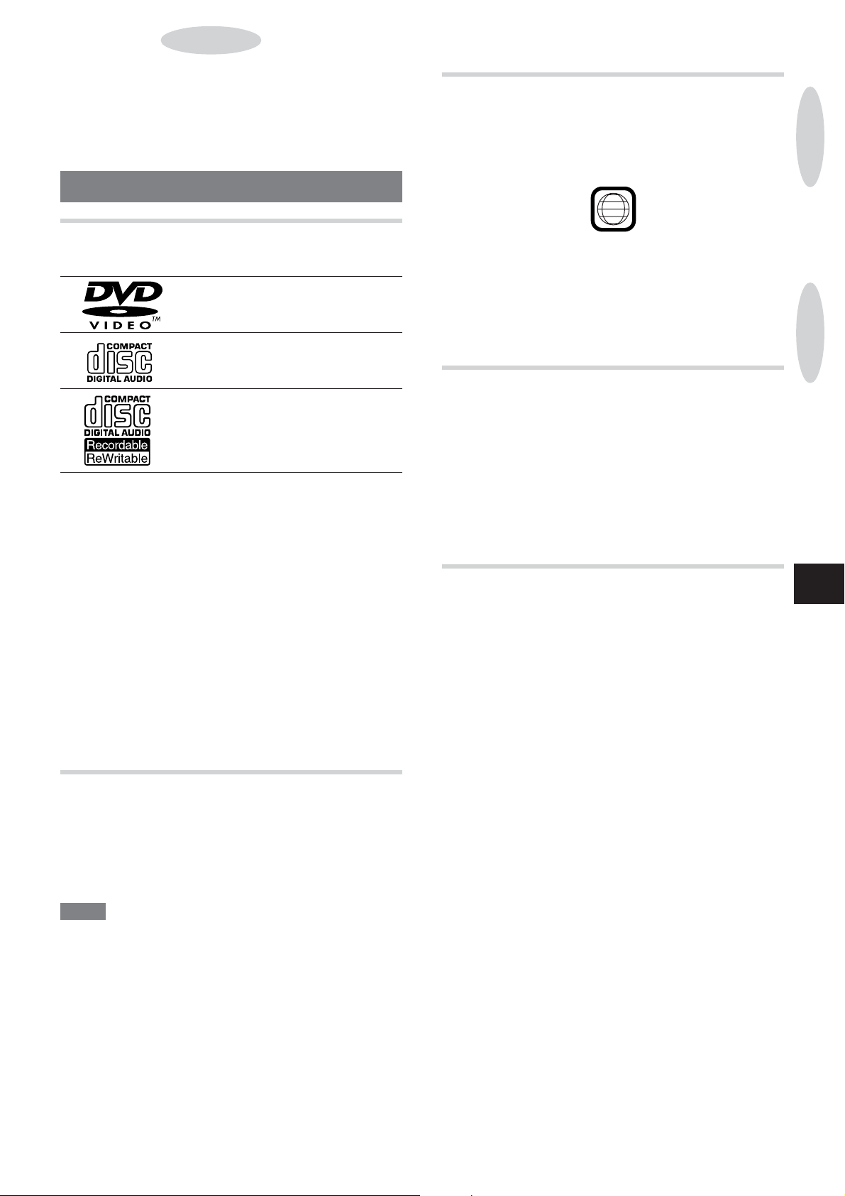
SUPPORTED DISC FORMATS
This unit can play discs with the following logos.
DVDs
(8 cm disc/12 cm disc)
Audio CDs (CDDA)
(8 cm disc/12 cm disc)
CD-R/RW
(8 cm disc/12 cm disc)
•This unit will play back an MP3-CD. See “DESCRIPTIONS OF
MP3”, page 14.
• This unit will play back a finalized CD-R/R W disc.
However, it may not play a CD-R/R W disc that is recorded on
personal computers or some kinds of CD-R/R W recorders
because of dif ferences in recording platforms.
• Do not load an unrecorded CD-R/R W disc. It will take over 30
seconds to read the disc. The disc may be damaged if you
open the disc compartment while the disc is being loaded.
• Do not attach any seal or label to either side (the recordable
side or the labeled side) of a CD-R/R W disc. It may cause
malfunction.
• This unit cannot play other types of discs such as DVD-ROMs,
CD-Is, CD-ROMs, PHOTO CDs or Aluminum-lined discs.
• Do not use irregular shaped CDs such as heart-shaped or
octagonal discs. It may damage both the unit and the disc.
COLOR SYSTEM SETTING
This unit is designed for the PAL and NTSC color system.
For the setting of color system, refer to “TV TYPE”, page 31.
“NTSC”: When connecting to a NTSC system TV . (Default)
“PAL”: When connecting to a P AL system TV.
“MULTI”: When connecting to a multi color system TV.
REGION CODE OF THE DISC PLA YER AND
DVDS
This DVD player is designed and manufactured for playback of
region “1” encoded DVD software. Region code appears on most
DVD labels to indicate which type of player can play the disc.
1
A DVD without a “1” or “ALL” on its disc label cannot be played on
this player . If you try to play such a disc, “WRONG REGION” on
the TV screen and “DISC ERR” on the unit’ s display will appear .
Some DVDs may not be properly labeled with a region code,
although they may be region encoded and thus be limited in its
playback area.
SOFTWARE DEPENDENT FEATURES OF
DVDS
Some playback operations of DVDs may be intentionally fixed by
software manufacturers. As this unit plays DVDs according to
the design of the software manufacturer , some playback features
of this player may not be available, while other functions may be
added.
Refer to the instructions supplied with the DVDs. Some DVDs
made for business purposes may not be played on this player .
DISC-RELA TED TERMS
Title (DVD only)
A title is the largest sub-division of a DVD; a movie for video
software, or an album for audio software.
Each title is assigned a title number , enabling you to locate the
title you want.
Chapter (DVD only)
Chapters are sections in a picture or a musical title on a DVD.
A title is usually composed of several chapters. Each chapter is
assigned a chapter number , enabling you to locate the chapter
you want.
Some discs, however , may not have chapters recorded.
Track (audio CD only)
Tracks are sections of a picture or a musical piece on an audio
CD.
Each track is assigned a track number , enabling you to locate
the track you want.
PREPARATIONS
PLAYING DVDS AND AUDIO CDS
En
NOTE
• This unit is designed for the NTSC and P AL systems only .
Systems other than NTSC or P AL, for example NTSC 4.43 or
SECAM are not suitable for this unit.
• If the color is abnormal or the picture is distorted in MUL TI
mode, switch to NTSC or P AL.
• If the disc of the NTSC (P AL) color system is played in P AL
(NTSC) setting, sometimes the picture is distorted. This is
because of the dif ference between the P AL and the NTSC
format.
ENGLISH
13

COPYRIGHT PROTECTION
It is forbidden by law to copy , broadcast, show , broadcast via
cable, play in public, or rent copyright material without permission.
This unit features the copy protection function developed by
Macrovision. Copy protection signals are included in some DVD
discs. If you record such discs on a VCR, picture noise will appear
during recording and playback.
This product incorporates copyright protection technology that
is protected by method claims of certain U.S. patents and other
intellectual property rights owned by Macrovision Corporation
and other rights owners. Use of this copyright protection
technology must be authorized by Macrovision Corporation, and
is intended for home and other limited viewing uses only , unless
otherwise authorized by Macrovision Corporation. Reverse
engineering or disassembly is prohibited.
DESCRIPTIONS OF MP3
• An MP3 file stores audio data compressed using MPEG1, the
audio layer-3 file-coding scheme.
• In this manual, CDs, CD-R discs and CD-R W discs are all
referred to as “discs”.
• Some files cannot be played back according to the recording
conditions of disc.
•Writing utilities
There are 3 utilities used to record data on a disc.
1.DAO (Disc At Once) utility
All data to be written must be prepared in advance and
written onto a disc from the beginning to the end in one
operation. No data can be added to a disc on which data
were already written with DAO utility .
2. TAO (Track At Once) utility
Data are written onto a disc file by file. Data can be added to
a disc on which data were written with TAO utility .
3. Packet writing utility
Files are divided into smaller pieces while being recorded,
depending on the size of available spaces on the disc. Data
can be added to a disc on which data were written with packet
writing utility .
This unit can play MP3 discs recorded using DAO and TAO
utilities.
• Multi-session
A session is a collection of data, covering from the beginning
to the end of recording made in one operation. W ith TAO (Track
At Once) utility , data can be recorded with several operations.
A session corresponds to the data recorded in one operation.
This unit can play data recorded in the first 2 operations. In
other words, the unit can play up to 2 sessions.
Notes on playing MP3 files
• An MP3 file must be recorded on a disc in the format compliant
with ISO 9660. Note, however , that the unit may not play files
in the order they were recorded.
• The maximum allowable number of files in a disc are as follows:
- number of files : 512 (including number of folders)
• The maximum allowable depth of nested folders is 8.
• It may take 30 seconds or more before the unit can start play
of MP3 files, depending on the number of recorded files and
the complexity of the folder tree.
•As for a multi-session disc, the unit can play up to 2 sessions.
• The unit may not play MP3 files recorded using a packet writing
utility .
• The unit can play MP3 files having a file extension “.mp3”.
• If you play a non-MP3 file that has the “.mp3” file extension,
you may hear some noise.
Notes on display indications during play
• Up to 11 characters are displayed for the name of a folder or a
file. ID3TAG information is not displayed. Characters other than
uppercase letters (“A” to “Z”), numerals (“0” to “9”) and an
underscore (_) may not be displayed correctly .
• The elapsed playing time may not be displayed correctly for
MP3 files.
Terminology
• ISO 9660
ISO stands for the “International Organization for
Standarization”. ISO 9660 determines the file structure for
the CD-ROMs. This unit can play MP3 files recorded in the
format compliant with ISO 9660.
SESSION 1 SESSION 2
SESSION 3
• Nesting of folders
To organize data files stored in a PC, you can store related
files in a folder . A folder can contain other folders as well as
files. For example, folder A can contain folder B, and folder B
can contain folder C; this is called “nesting of folders”. The
maximum depth of nested folders, allowed by ISO 9660, is 8.
14
ENGLISH

• File extension
A 3-character string added to a file name under W indows or
DOS environment is called “file extension”. A file extension is
used mainly to identify types of files. File extension for MP3
files is “.mp3”.
Notes on creating MP3 discs
• When converting audio data to MP3
To enjoy high sound quality , we recommend storing MP3 files
with a sampling frequency of 44.1 kHz and a fixed bit rate of
128 kbps.
• When creating MP3 discs
Do not store more than 512 folders and files in a disc.
•To play files in the order they were recorded
1. Use a writing software capable of recording MP3 files in
numerical and alphabetical order . For details on using the
software, refer to the operating instructions supplied with
the software.
2. Use only one folder . (Do not create a sub-folder within a
folder .)
3.Include a two- or three- digit number at the beginning of
each folder or file name so that the folders and files are
played in order .
<example of recommended names>
01XXXXX.mp3
02XXXXX.mp3
03XXXXX.mp3
04XXXXX.mp3
05XXXXX.mp3
<example of names not recommended>
1XXXXX.mp3
5XXXXX.mp3
10XXXXX.mp3
15XXXXX.mp3
20XXXXX.mp3
(Numbers at the beginning have dif ferent digit number .
The tracks will not be played in this order but played in
the order of “1”, “10”, “15”, “20” and “5”.)
• Do not record other format (CDDA etc.,) in MP3 disc. It may
not be played back properly
BASIC OPERATIONS
PLAYING A DISC
1
To play a DVD, turn on the TV and select the proper
input.
On your TV, select the input from the VIDEO OUT jack (or the
S-VIDEO OUT jack, if you are using S-video) of this unit.
2
Select DVD/CD function.
Press FUNCTION repeatedly on the main unit or press DVD/
CD on the remote control.
3
Press zOPEN/CLOSE to open the disc tray.
PLAYING DVDS AND AUDIO CDS
En
4
Place a disc with the labeled side up.
5
Press zOPEN/CLOSE again to close the disc tray .
“LOADING” is displayed while the player loads the disc.
If the disc is not placed correctly , “NO DISC” or “DISC ERR”
appears on the unit’ s display .
ENGLISH
15

DVDs:
Playback starts automatically .
If the menu is displayed, see “USING THE MENU”, below .
STOPPING AND P AUSING
To stop playback
Press s.
Playback stops. For DVDs, “RESUME” appears and the unit
remembers the point at which playback stopped.
Title number
To switch the number between title and chapter , press
SHIFT+TITLE/CHP. With each press, title or chapter is
displayed alternately .
Audio CDs function:
Total number of tracks
6
If playback does not start automatically , press c
Elapsed time of current title
Total playing time
to start playback.
To play back DVDs recorded in Dolby Digital or DTS sound
See section “SURROUND PLA YBACK” (pages 24-26).
To play back an MP3 disc
Menu screen (SMAR T NAVI) appears on the TV screen after the
disc is loaded.
1. Press i,k,j or l to select PLA Y MODE.
SHIFT+PRGM, RANDOM or REPEAT is also available.
For the programed playback, see page 20.
2. Press i,k,j or l to select the folder and press ENTER.
3. Press i,k,j or l to select the file.
4. Press c to start playback.
When the play mode is program, the program file is added
each time c is pressed. To start playback, press s and then
press c.
• 0-9 is also available to select the file up to 2 digit number .
The file with
properly .
cannot be played back since it cannot be read
To resume playback from the point where it stopped (DVD
only)
Press c.
Playback starts where it last stopped (Resume function).
To clear the point to be resumed (DVD only)
Press s again during stop.
“STOP” appears in the TV display . The resume memory is cleared,
and playback starts at the beginning of the disc when c is
pressed.
Last scene function (DVD only)
If the disc is taken out or s is pressed to clear the resume
memory, resume function is still ef fective (up to 7 discs). Next
time the disc is loaded, “PRESS PLA Y TO RESUME PLAY”
appears on the TV screen. T o resume playback, press c while
the message is displayed. If a new disc is loaded when the
memory is full, the resume data for the oldest disc is erased.
Last screen function may not work with some discs.
To pause playback
Press a.
To resume playback, press c.
NOTE
• DVD playback is resumed with the subtitle and audio language
setting at the time it was stopped, regardless of possible later
changes.
• During stop of MP3 disc or resume of DVD, the disc is still
spinning.
NOTE
• When loading an 8-cm (3-inch) disc, put it onto the inner circle
of the slot.
• Do not place more than one disc.
• Do not tilt the unit with disc loaded. Doing so may cause
malfunctions.
USING THE MENU
DVDs with the menu function may automatically display the menu
screen when the disc is loaded. Operate the menu as follows.
DVDs
1
Press i, k , j, or l to select your desired
program.
2
Press ENTER to begin playback.
To manually display the menu
Press MENU or TOP MENU during playback or stop.
NOTE
• The disc continues to spin as long as the menu is displayed.
• The contents and operation of the software specific menu vary
with the disc. Follow the instructions on the disc and on the
menu screen.
16
ENGLISH

SELECTING A TRACK
Besides the methods described here, discs can also be searched
by title/chapter (DVDs), track (CDs) or time. See “ON SCREEN
DISPLAY INFORMATION”, page 23.
SKIPPING
Press r or t during playback.
With each press of t, the disc position skips to the succeeding
tracks (CDs) or chapters (DVDs).
When r is pressed once, the disc position skips back to the
beginning of the current tracks (CDs) or chapters (DVDs).
When r is pressed twice or more, the disc position skips back
to the previous tracks (CDs) or chapters (DVDs).
Depending on scenes, this operation may not function on DVDs.
PLAYING DVDS AND AUDIO CDS
DIRECTL Y SELECTING A TRACK WITH THE
REMOTE CONTROL (CD ONLY)
A track can be selected directly by entering the track number on
the remote control, either during playback or stop.
Press 0-9 to select the desired track.
Example:
To play track 12, press 1, 2.
To play track 20, press 2, 0.
Playback begins at the beginning of the selected track and
continues to the end of the disc.
FAST FORWARD/REVERSE PLA YBACK
Press f or g on the remote control or hold
down f or g on the main unit during playback.
“-SCAN x 2” or “ +SCAN x 2” is displayed on the TV screen.
The disc is played back forward (when pressing g) or in reverse
(when pressing f) at high speed.
To change playback speed
Press f or g on the remote control (hold down f or g
on the main unit) repeatedly .
With each press:
DVDs:
x 2 x 4 x 16 x 100
En
x 2 x 4 x 8
CDs:
To return to normal playback
Press c.
NOTE
•There is no audio during fast DVD playback.
•The fast playback speed is the value for a disc with an average
bit rate. The actual speed may be dif ferent for some discs.
•If the search reaches the beginning or the end of a track, it
automatically returns to normal playback. (CDs)
ENGLISH
17

FRAME ADVANCE AND SLOW PLAYBACK
FRAME ADVANCE (DVD ONLY)
REPEAT PLAYBACK
REPEA T PLA YBACK (DVD)
Press SHIFT+REPEAT repeatedly on the remote
control during playback.
With each press, the Repeat playback mode changes:
1
Press a to pause the disc.
2
Press a repeatedly to advance frames.
With each press, playback advances one frame.
To return to normal playback
Press c.
NOTE
There is no audio during Frame Advance.
SLOW PLA YBACK (DVD ONL Y)
Press SHIFT+ SLOWG or SLOWF on the remote
control during playback
To change the slow playback speed
With each press, the playback speed changes as follows:
1/2 1/4 1/8
To return to normal playback
Press c.
NOTE
There is no audio during slow playback.
CHAPTER: Repeats the current chapter .
TV screen:
CHAPTER REPEAT ON
TITLE: Repeats the current title.
TITLE REPEAT ON
OFF: Cancels repeat mode. (Normal playback)
REPEAT OFF
18
ENGLISH

REPEA T PLAYBACK (CDs)
PROGRAMED PLAYBACK
Press SHIFT+REPEAT repeatedly on the remote
control during playback.
With each press, the Repeat playback mode changes:
ONE: Repeats the current track.
TV screen:
REPEAT ONE
ALL: Repeats all tracks on the disc.
REPEAT ALL
OFF: Cancels repeat mode. (Normal playback)
REPEAT OFF
Unit’s display
(CD ONLY)
You can program up to 32 selected tracks to be played back in
your desired order .
If the total playing time of the program exceeds 99 minutes and
59 seconds, the playing time is not displayed properly .
1
Press SHIFT+PRGM on the remote control during
stop.
“PRGM” lights up on the unit’ s display .
PLAYING DVDS AND AUDIO CDS
To repeat playback of selected track(s)
Program the track(s) with the programed playback function, and
then press SHIFT+REPEA T to repeat playback of the programed
tracks (see “PROGRAMED PLA YBACK”, below).
2
Press 0-9 on the remote control to select the track.
Example:
To select track 12, press 1, 2.
To select track 20, press 2, 0.
3
Press ENTER.
The selected track is programed.
4
Repeat steps 2 and 3 to program other tracks.
5
Press c to start playback.
The programed tracks are played back in the order of entry .
To stop programed playback
Press s.
To return to normal playback mode
Press SHIFT+PRGM during stop. At this point, the program is
not cleared. Pressing SHIFT+PRGM again will be back to
programed playback mode.
En
ENGLISH
19

RANDOM ON
To check the program
Press i or k repeatedly during stop in programed playback
mode.
With each press, the track numbers appear in the order
programed on the unit’ s display .
To clear the program
Press C during stop in the programed playback mode.
• The program is also cleared in the following cases.
- The disc tray is opened.
- The function is switched.
- The power is turned of f.
To clear a programed track
Press i or k to display the track, and then press C.
To add tracks to the program
Press i to display the last order , and then repeat steps 2 and 3
during stop in the programed mode. The new tracks are added
to the end of the program.
Programed playback for MP3 disc
1. Press SHIFT + PRGM to enter the program mode.
Selecting “PROG-END” from PLA Y MODE with i,k,j or l
also enters the program mode.
2. Press i,k,j or l to select the folder and press ENTER.
3. Press i,k,j or l to select the file to be programed.
4. Press c or ENTER.
The selected file is programed.
RANDOM PLAYBACK (CD ONLY)
All tracks on the disc can be played randomly .
1
Press SHIFT+RANDOM during stop.
“RANDOM ON” appears on the TV screen and “RANDOM”
lights up on the unit’ s diaplay .
Total programed file
Current programed file
PROGRAM P04-13
5. Repeat steps 2, 3 and 4 to program other files.
6. Press s and then press c to start playback.
NOTE
• Next time the unit enters the program mode, the previous
program is cleared
2
Press c to start random playback.
To stop random playback
Press s.
To cancel random playback
Press SHIFT+RANDOM again during stop. “RANDOM OFF”
appears on the TV screen and “RANDOM” disappears and the
unit goes back to normal playback.
NOTE
During random playback you cannot skip back to the previously
played track with r.
20
ENGLISH

SPECIAL DVD FEATURES
Operations for special features characteristic to DVDs are
described here.
SUBTITLES (DVD ONLY)
You can also change the subtitle language if more than one is
available.
Press SUBTITLE on the remote control repeatedly
during playback to select the desired subtitle
language.
With each press, the subtitle will change.
ZOOM FUNCTION (DVD ONLY)
Press SHIFT+ZOOM on the remote control during
playback.
The picture around the center of the screen is enlarged.
With each press:
x4 x16
To move the enlarged picture
Press i, k, j, or l.
Normal playback
CHANGING THE ANGLE (DVD ONLY)
When playing back a scene shot with multi-angles, you can select
the angle to view the scene.
“ANGLE AREA IN” or “ANGLE AREA OUT” appears on the TV
screen to show whether the Angle function is ef fective or not.
1 ENG
He’s having a great run today, Jim.
OFF
NOTE
• If you press SUBTITLE when playing a disc without subtitles,
the “OFF” is displayed.
• The subtitle language can be changed only if the disc contains
more than one subtitle language.
• It may take some discs a few moments after you press
SUBTITLE until the new subtitles are displayed.
• Some discs permit switching the subtitle language only through
a menu screen.
Jim, lui, roule trés bien aujourd´ hui.
Jaime está corriendo muy bien.
2 FRE
3 SPA
PLAYING DVDS AND AUDIO CDS
En
Press ANGLE on the remote control repeatedly
to select a viewing angle.
With each press, the angle will change.
1
4
NOTE
The Angle function works only when playing back a shot with
multi-angles. If you press
or a disc without multiple viewing angles, the
displayed.
ANGLE when playing back a scene
2
3
symbol is
ENGLISH
21

CHANGING AUDIO TRACKS (DVD ONLY)
USING A TITLE MENU (DVD ONLY)
Some DVDs have more than one audio tracks, such as
soundtracks in dif ferent languages. Y ou can change the audio
track when playing such discs.
Press AUDIO on the remote control during playback.
With each press, the audio track will change.
1 ENG PCM
2 FRE PCM
For signal type information, see “ON SCREEN DISPLA Y
INFORMATION”, page 23.
NOTE
• The audio track can be changed only if the disc contains
multiple audio tracks. The number of available audio tracks
varies with the disc.
• Some discs permit switching the audio track only through a
menu screen.
Total channel number
Signal type
Audio language
CHANGING AUDIO CHANNELS (CDs ONLY)
Use this function when playing CDs with dif ferent sound tracks
in the left and right channels.
Press AUDIO repeatedly during playback.
With each press, the audio channel will change.
MONO LEFT MONO RIGHT STEREO
Some DVDs have two or more titles and one of them can be
selected.
1
Press TOP MENU during playback.
The title menu appears on the TV screen.
• Pressing vRETURN resumes playback at the scene from
which the title menu was called.
Example:
TITLE MENU
Rivers
Lovers
2
Press i, k, j or l to select the title and then
Castles
Woods
press c or ENTER.
0-9 are also available to select the title.
The playback starts.
NOTE
• The contents and operation of the software specific menu vary
with the disc. Follow the instructions on the disc and on the
menu screen.
USING A DVD MENU
Use this menu to select content, audio, subtitles, etc., from a
menu (the DVD menu) that is unique to each disc.
1
Press MENU during playback.
The DVD menu appears on the TV screen.
• Pressing vRETURN resumes playback at the scene from
which the DVD menu was called.
Example:
DVD MENU
1 SUBTITLE
2 AUDIO
3 ANGLE
- MONO LEFT: left audio channel is output from both front
speakers
- MONO RIGHT : right audio channel is output from both front
speakers
- STEREO: normal stereo playback
22
ENGLISH
2
Press i, k, j or l to select the menu item and
then press ENTER.
0-9 are also available to select the menu item.
The playback starts.
NOTE
• The contents and operation of the software specific menu vary
with the disc. Follow the instructions on the disc and on the
menu screen.

ON SCREEN DISPLAY INFORMATION
The information of current disc is displayed on the TV screen
and you can select title, chapter or audio language etc.
[DVD]
Press j or l to select the desired item.
123 4 5 6
1 shows the title number .
Press 0-9 to select the desired title and then press
ENTER.
2 shows the chapter number .
Press 0-9 to select the desired chapter and then press
ENTER.
PLAYING DVDS AND AUDIO CDS
Press ON SCREEN on the remote control during
playback.
On screen display information is displayed on the TV screen.
When the menu screen is displayed, on screen display
information is not displayed.
[CD]
1 shows the current track/total tracks.
2 shows the elapsed playing time.
12
Press 0-9 to select the desired track and press
ENTER.
3 shows the elapsed playing time.
Press 0-9 to input the desired time and then press
ENTER.
Example:
To specify 1:17:30 (1 hour 17 minutes 30 seconds),
press 1, 1, 7, 3 and 0.
To specify 0:08:07 (8 minutes 7 seconds), press 8, 0
and 7.
4 shows the audio sound track language and the audio
signal type.
Press AUDIO to select the desired audio track.
For the audio signal type information, one of the
following will be displayed;
: Dolby Digital signal.
dts: DTS signal.
PCM: Linear PCM signal.
MP: MPEG audio signal.
For the number of audio channel, for example,
= [Conventional stereo] two front channels (left
and right) and no rear channel.
= [5.1-channel surround] three front channels
(left, right and center), two rear channels (left rear and
right rear) and LFE (Low Frequency Ef fects).
5 shows the subtitle information.
Press SUBTITILE to select the desired subtitle
language.
En
6 shows the angle information.
Press ANGLE to select the desired angle.
To clear ON SCREEN DISPLAY
Press ON SCREEN again.
To move ON SCREEN DISPLAY up or down
Press i or k.
ENGLISH
23

SURROUND PLAYBACK
This unit comes equipped with a built-in Dolby Digital
decoder, Dolby Pro Logic decoder and a DTS decoder.
With this unit’ s built-in Dolby Digital decoder , Dolby Pro Logic
decoder , DTS decoder and the speaker system (the center ,
surround speaker units and the subwoofer supplied in addition
to the left and right front speakers), Dolby Digital, Dolby Pro Logic,
or DTS sources can be played back in full scale home theater
sound.
Dialogs are heard in the front and center sound field, while
ambient sounds like cars and crowds are reproduced on all sides
of the listener , all in all for an incredibly lifelike audio-visual
experience.
Dolby Digital and DTS are multichannel system (maximum 5.1
channel) which record audio signals digitally .
5.1 channel means left, center and right front channels, separate
left and right surround channels, plus a low-frequency ef fects
(LFE) channel, counted as “0.1” channel.
Dolby Digital and DTS tracks may also come in 1 or 2 channels
(monaural or stereo, respectively), or in fact, any number of
channels within the limit. (Sources with 3 or more channels will
a
be refered to as
Dolby Digital software is marked with the
DTS software is marked with the
Dolby Pro Logic is an analog audio multichannel system with
four independent channels; left, center , right, and surround. These
four channels are coded into the two tracks of a conventional
analog stereo source.
Dolby Pro Logic VCR software is marked with the
Hlogo.
NOTE
• This unit does not support multichannel playback of MPEG
Multichannel sources.
• Make sure all the supplied speakers are placed and connected
properly (pages 5 and 6).
multichannel
source) .
logo.
logo.
PLAYING WITH SURROUND SOUND
1
Play back the surround source.
• Make sure to select the video input from this unit on your
TV.
• DVDs may contain several audio tracks, such as a Dolby
Digital track and a DTS track, or Dolby Digital tracks in
different channel configurations, etc.
If necessary , press AUDIO on the remote control to change
the playback track (page 22).
2
Press SURROUND repeatedly to select the
desired surround mode.
With each press:
For a Dolby Digital/DTS multichannel source
DOLBY DIGITAL/DIGITAL THEATER STEREO
DOLBY DIGIT AL/DIGITAL THEATER: multichannel surround
sound
STEREO: 2 channel stereo sound (Select this mode when
neither the center nor the surround speaker units are
connected.)
For a Dolby Digital 2 ch source
PRO LOGIC STEREO
For a source except stated above
(Linear PCM or ANALOG, etc.)
PRO LOGIC THEATER HALL STADIUM
24
STEREO
PRO LOGIC: Surround sound
THEATER: Sound presence of a theater
HALL: Sound presence of a concert hall
STADIUM: Sound presence of a stadium
STEREO: Normal stereo playback
• The signal type indicator lights up according to the signal
type and other conditions (see “SURROUND PLA YBACK
MODE INDICATION”, page 25).
To adjust the sound level of the speakers during playback
See “ADJUSTING SPEAKER LEVELS”, page 28.
NOTE
• When the headphones are plugged in, surround mode
automatically switches to the STEREO mode.
• When playing back 96 kHz Linear PCM source, surround mode
automatically switches to the STEREO mode.
ENGLISH

SURROUND PLA YBACK MODE INDICA TION
The “ h DIGIT AL”, “dts” and “ h PRO LOGIC” indicators show
your present playback condition as follows;
“h DIGIT AL” indicator lights up...
when a Dolby Digital source is played back.
“dts” indicator lights up...
when a DTS source is played back.
“h PRO LOGIC” indicator lights up...
when a 2-channel source, such as the following, is played back
with PRO LOGIC mode:
• Dolby Pro Logic source (such as a video cassette recorded in
Pro Logic played back on a connected VCR player)
• 2-channel Dolby Digital source (DVD etc.,)
If the source does not play in your desired
playback mode
Your actual surround playback condition is determined by a
number of factors. Check the following;
type of signal and number of channels on your source
–
For example, a Dolby Digital or a DTS disc may come in
its full 5.1 channels, or in 2 channels, etc. Press ON
SCREEN on the remote control to check the audio signal
type information.
See “ON SCREEN DISPLAY INFORMATION”, page 23.
selected track
–
Your disc may of fer a choice among several types of sound
mixes. Check that your desired mix is selected with the
AUDIO button on the remote control.
See “CHANGING AUDIO TRACKS”, page 22.
type of connection
–
If you are using analog connection, Dolby Digital or DTS
playback is disabled.
SPEAKER SETTING
NOTE
• When the remote control is VIDEO 1, VIDEO 2, TV or CABLE/
SAT . mode, press i,k,jor l with pressing SHIFT.
SETTING UP THE SPEAKER SIZE
You can set each speaker size and whether they are present or
not.
1
Press SHIFT+SP SETUP.
2
Press i or k to select “SP SIZE”.
With each press:
SP SIZE SP DIST BALANCE TEST TONE
3
Press l .
SURROUND PLAYBACK
En
4
Press i or k to select the speaker for setting.
With each press:
FRONT CENTER SURROUND SW
5
Press l .
6
Press i or k to select the speaker type.
With each press:
FRONT:
CENTER:
SURROUND:
SW:
LARGE: Large speaker . When bass playback is possible. (100
Hz or lower is the target.)
SMALL: Small speaker . When bass playback is not possible.
NONE: When not using the center or the surround speakers.
YES: When using a subwoofer .
NO: When not using a subwoofer .
(Default: F-SMALL, C-SMALL, S-SMALL, SW -YES)
7
Press l.
“ENTER” flashes. Then the selected item is displayed. If you
set other speaker , press l to go back to step 4.
When the setting is not changed, the unit goes back to step
4.
F-LARGE F-SMALL
C-LARGE C-SMALL C-NONE
S-LARGE S-SMALL S-NONE
SW-YES SW-NO
ENGLISH
25

8
SP SIZE SP DIST BALANCE TEST TONE
Press SHIFT+SP SETUP.
The setting is completed.
NOTE
• When “F-SMALL” is selected, “SW -YES” is automatically set
and cannot be changed.
• “CENTER” and “SURROUND” cannot be set when STEREO
mode is selected. (See “PLA YING WITH SURROUND SOUND”,
page 24)
ADJUSTING THE SPEAKER DIST ANCE
Adjusts the speaker distance so that sounds from each speaker
can reach the listening position at the same time.
1
Press SHIFT+SP SETUP.
2
Press i or k to select “SP DIST”.
With each press:
SP SIZE SP DIST BALANCE TEST TONE
3
Press l .
4
Press i or k to select the speaker for setting.
With each press:
FRONT CENTER SURROUND
ADJUSTING THE SPEAKER CHANNEL
LEVEL
Using a test signal, the sound level of all available channels should
be adjusted so that the volume level from each speaker sounds
equal.
1
Press SHIFT+SP SETUP.
2
Press i or k to select “TEST TONE”.
With each press:
3
Press l .
The test signal automatically cycles through the channels in
the following order:
LCRRSLS
(L: Left front, C: Center , R: Right front, RS: Right Surround,
LS: Left Surround)
4
While the desired channel is displayed, press i
or k to adjust the channel level.
Adjustable range: –10 to +10(dB)
5
Press SHIFT+SP SETUP.
The setting is completed.
5
Press l .
6
Press i or k to adjust the distance from each
speaker to the listening position.
Default:
FRONT:
CENTER:
SURROUND: S 12FT (feet)
Adjustable range: 1FT to 30FT (for each speaker)
7
Press l.
The adjusted level is set and back to step 4.
8
Press SHIFT+SP SETUP.
The setting is completed.
F 17FT (feet)
C 17FT (feet)
ADJUSTING THE LEVEL BALANCE OF THE
FRONT SPEAKERS
1
Press SHIFT+SP SETUP.
2
Press i or k to select “BALANCE”.
With each press:
SP SIZE SP DIST BALANCE TEST TONE
NOTE
• When the volume level is set to 80, any one of speaker channel
level cannot be set to more than +1 dB.
•When the surround mode is set to the STEREO mode (page
24), the speaker channel level cannot be adjusted.
3
Press l .
4
Press i or k to adjust the level balnce.
Default:
L 0dB (Left front)
R 0dB (Right front)
Press l to switch the display between “L” and “R”.
5
Press SHIFT+SP SETUP.
The setting is completed.
26
ENGLISH

RADIO RECEPTION
Your receiver can receive FM and AM radio broadcast.
RADIO RECEPTION
PRESET TUNING
The unit can store up to 32 preset stations for each band (FM,
AM). Presetting allows you to tune in to a station directly . 5 stations
are preset with test frequency for each band. (factory setting)
Automatic Presetting
The tuner scans through the receivable frequency range and
stores stations automatically .
1
Select the band.
2
Hold down SETa for 3 seconds.
The tuner searches for a station.
Stations with weak signals may not be stored.
To stop automatic presetting manually
Press SETa again.
NOTE
If you use automatic presetting, previously stored stations are
overwritten.
Manual Presetting
1
Press PRESET c to display “TUNING”.
SURROUND PLAYBACK
RADIO RECEPTION
MANUAL TUNING
1
Press FUNCTION repeatedly to select TUNER
function.
On the remote control, press TUNER/BAND.
2
Press BAND to select a band.
On the remote control, press TUNER/BAND.
3
Press PRESET c to display “TUNING”.
4
Press TUNING + or - to select a station.
"TUNE" lights up during radio reception.
"1" lights up for FM stereo reception.
AUTO SEARCH
1
Select a band.
2
Press PRESET c to display “TUNING”.
3
Hold down TUNING + or - until the search
begins.
The unit starts searching the band, and stops when it tunes
in to a station.
To stop auto search manually
++
Press TUNING
NOTE
Auto search may not stop at stations with weak signals.
+ or
++
--
-.
--
2
Tune in to the desired station.
3
Press SETa.
4
Within 5 seconds, press TUNING + or - to select
preset number.
5
Press SETa to store the station.
Preset Tuning
On the main unit
1
Select the band.
2
Press PRESET c to display “PRESET”.
3
Press TUNING+ or - to select the preset number .
On the remote control
1
Select the band.
2
Press 0-9 to enter the preset number.
Example:
To select 21, press, 2, 1.
To clear a station preset
1Tune in to the station to be cleared by preset tuning.
The preset will not be cleared if you tuned in to a station by
manual tuning.
2 Press
ss
s.
ss
The preset is cleared.
En
ENGLISH
27

SOUND AND TIMER ADJUSTMENTS
ADJUSTMENTS
ADJUSTING THE ANTENNAS
FM antenna:
Extend fully and position for the best possible reception.
An outdoor antenna is recommended for better reception. See
“CONNECTING AN OUTDOOR ANTENNA”, page 8.
AM antenna:
Position and rotate the antenna to find the best reception.
Changing FM reception to monaural
Press SHIFT+MONO TU on the remote control. “MONO” appears
on the display .
Monaural reception will reduce noise if FM stereo reception
contains noise.
To return to stereo reception, repeat the above.
If reception contains noise interference
Move the unit away from other electrical appliances, especially
digital audio devices, or turn of f the appliances that generate
noise signals.
Changing the AM tuning interval
The default tuning interval of the receiver is 10 kHz/step. When
using the receiver in a 9 kHz/step area, change the tuning interval.
Select AM band and hold down BAND on the main unit.
Repeat to return to 10 kHz/step.
NOTE
Changing the AM tuning interval will return the station presets to
the initial setting.
Sound and timer adjustment are possible on this unit.
SOUND ADJUSTMENTS
ADJUSTING SPEAKER LEVELS
First, adjust the speaker levels with a test signal (page 26). After
that, if needed, adjust the speaker levels by following way with
playing back a software.
Press SUBWOOFER(+,-), CENTER(+,-) or REAR
(+,-) on the remote control to adjust subwoofer,
center or surround speakers level.
NOTE
• When the volume level is set to 80, any one of speaker channel
level cannot be set to more than +1 dB.
ADJUSTING THE BASS/TREBLE LEVEL
1
Press BASS/TREBLE repeatedly to select “BAS”
or “TRE”.
2
Turn VOLUME (press VOLUME+ or - on the
remote control) to adjust bass/treble level.
Adjustable range: –10 to +10 (dB)
NOTE
• BASS/TREBLE is only ef fective for front speakers and
headphone.
MUTING SOUND
Press MUTE on the remote control.
“MUTE” appears on the display , and sound from the speakers or
the headphones is muted.
To cancel muting
Press MUTE again.
28
ENGLISH

CUSTOMIZING DVD SETUP
ADJUSTING DYNAMIC RANGE (DOLBY
DIGITAL)
In Dolby Digital, dynamic range between soft and loud sounds
can be adjusted to suit your desired playback volume.
1
Play the Dolby Digital sound.
See “PLAYING WITH SURROUND SOUND”, page 24.
2
Press SHIFT+MIDNIGHT repeatedly to select
desired mode.
[NIGHT MIN]
Minimum dynamic range compression. Enjoy the full dynamic
range of the sound track as experienced in a movie theater .
[NIGHT STD]
Standard dynamic range compression recommended by the
software producers when playing back at home. Default.
[NIGHT MAX]
Maximum dynamic range compression. Keeps soft sounds
and dialogs intelligible even with the overall volume turned
down. Select this mode when you have to keep the volume
low, for example, when playing back late at night.
SLEEP TIMER
This unit can be set to turn of f automatically after a specified
period of time.
Press SLEEP repeatedly to set the sleep timer
duration.
On the remote control, press SHIFT+SLEEP.
The sleep-time can be changed from 10 to 90 minutes in 10minute steps.
Various default settings related to the DVD player and the
TV monitor can be changed as needed or preferred.
OVERVIEW OF THE SETUP MENU
There are 4 major menu items that can be adjusted. Their function
are as follows:
1RATING (page 30)
Sets the rating limit of DVDs allowed to play back on this unit
when playing discs with restriction level encoding.
With discs that include scenes with excessive violence, for
example, this setting can be used either to automatically cut
such scenes or to disable playback altogether , depending on
the disc.
2PASSWORD (page 30)
The password needs to be entered not to prevent the playback
of the disc whose rating level is higher than the unit’ s setting.
The password can be changed to your taste.
When the password is required, even if you input the wrong
password, the password cannot be cleared. Be careful not to
input the wrong password. If you fail in inputting password,
reinsert the disc and then repeat the procedure.
3 TV DISPLAY (page 31)
Sets the aspect ratio of the video signal sent to your connected
TV set. The preference setting for the 4:3 or 16:9
representation of wide format software is only ef fective when
playing a disc of fering such a choice.
4 TV TYPE (page 31)
Sets “TV TYPE” according to the color system of the connected
TV.
RADIO RECEPTION
ADJUSTMNTS
SOUND AND TIMER
DVD SETUP
CUSTOMIZING
En
To check the time remaining until the power turns off
Press SLEEP once (press SHIFT+SLEEP on the remote control).
The remaining time is displayed for 4 seconds.
To cancel the sleep timer
Press SLEEP (press SHIFT+SLEEP on the remote control)
repeatedly to clear the sleep-timer display .
The “TV DISPLAY” setting and the “TV TYPE” setting
need to be set specifically to match your configuration of
connected equipment.
• The default “TV DISPLA Y” setting has to be changed if
you are connecting to a 16:9 (wide) ratio TV set.
• Changing the default “TV TYPE” may be needed depending
on your TV type.
Any other setting can be changed or kept as is, according
to your preferences.
ENGLISH
29

BASIC MENU OPERATIONS
RATING
PASSWORD
TV DISPLAY
TV TYPE
UNLOCK
INPUT - - - 4:3 /LB
NTSC
SETUP MENU
PLEASE ENTER PASSWORD
RATING
PASSWORD
TV DISPLAY
TV TYPE
OLD : - - - NEW: - - - 4:3 /LB
NTSC
SETUP MENU
PLEASE ENTER OLD PASSWORD
RATING
Basic operation of the SETUP MENU is described here.
1
Select DVD/CD function.
Press FUNCTION repeatedly on the main unit or press DVD/
CD on the remote control.
2
Press SETUP.
The “SETUP MENU” screen is displayed.
SETUP MENU
RATING
PASSWORD
TV DISPLAY
TV TYPE
SET RATING
3
Press i or k to select the item to be changed.
4
Press ENTER to select the desired setting.
5
Press SETUP.
UNLOCK
CHANGE
4:3 /LB
NTSC
Sets the rating limit allowed to playback on this unit when playing
discs with restriction level encoding. To change the restriction
level, you have to input the password.
The default setting is “UNLOCK”.
Select “RATING” in the “SETUP MENU”.
1
Press ENTER.
2
Use 0-9 to input password.
3
default: 1234
Press ENTER.
4
Press ENTER repeatedly to select your desired level.
5
“UNLOCK” cancels the rating level.
The smaller the number , the higher the level of restriction.
For instance, setting the rating level to 1 will restrict playback
of all discs with a rating level from 2 to 8, either by cutting
certain scenes or disabling playback altogether , depending on
the disc.
Check your disc for details.
Press SETUP.
6
The setting is completed.
PASSWORD
The password needs to be entered not to prevent the playback
of the disc whose rating level is higher than the unit’ s setting.
The password can be changed to your taste.
Select “PASSWORD” in the “SETUP MENU” and press
1
ENTER.
To exit the setup menu
Press SETUP.
To confirm your setting
1 Press SETUP to display the setup menu.
2 Press SETUP again to exit the setup menu without making
changes.
NOTE
•While the setup screen is displayed, you will not be able to
perform other operations on the unit. Press SETUP again to
exit the setup screen first.
30
ENGLISH
Use 0-9 to input four-digit old password.
2
default: 1234
Use 0-9 to input four-digit new password.
3
Do not forget the password you set!
Press ENTER.
4
Press SETUP.
5
The setting is completed.
If you forget your password (Resetting the DVD setup)
1 Press SETUP to display SETUP MENU.
2 Select “RA TING” in the “SETUP MENU” and press ENTER.
3 Input four-digit number “2580” and press ENTER.
All the item of the DVD setup are reset.

TV DISPLAY
RATING
PASSWORD
TV DISPLAY
TV TYPE
UNLOCK
CHANGE
4:3 /LB
NTSC
SETUP MENU
SET TV STANDARD
TV TYPE
Sets the aspect ratio of the video signal sent to your connected
TV set.
SETUP MENU
RATING
PASSWORD
TV DISPLAY
TV TYPE
SET TV DISPLAY MODE
UNLOCK
CHANGE
4:3 /LB
NTSC
The default setting is “4:3 /LB (letterbox)”.
If you are connecting to a 16:9 (wide) ratio TV set, change the
setting to “16:9 WIDE”.
Select “TV DISPLA Y” in the “SETUP MENU”.
1
Press ENTER repeatedly to select the desired setting.
2
“4:3/LB (Letter Box)”
Media recorded in wide (16:9) format will be played in
“letterbox” style, with black bands at the top and bottom of the
screen.
“4:3/PS (Pan & Scan)”
Media recorded in wide (16:9) format will be played at the full
screen height, with the left and right portions cut of f.
Set “TV TYPE” according to the color system of the connected
TV.
Select “TV TYPE” in the “SETUP MENU”.
1
Press ENTER to select the desired setting.
2
“NTSC”
When connencting to a NTSC system TV. (Default)
“P AL”
When connencting to a P AL system TV.
“MULTI”
When connencting to a multi color system TV.
Press SETUP.
3
When the SETUP MENU screen is not displayed properly .
1. Press SETUP to exit the SETUP MENU
2. Hold down BAND repeatedly until NTSC, P AL or MULTI is
displayed on the TV screen. The setting with BAND button is
temporary . If the disc is removed or the function is changed,
the setting is canceled. When you change the setting with
BAND button, the setting of the SETUP MENU also needs to
be changed.
CUSTOMIZING DVD SETUP
En
“16:9 WIDE”
Select this when a wide-screen TV is connected. Media
recorded in wide (16:9) format can be played on the full screen.
(The wide-screen TV also needs to be set to wide-screen.)
Press SETUP.
3
The setting is completed.
NOTE
• If the color is abnormal or the picture is distorted in MUL TI
mode, switch to NTSC or P AL.
• If the disc of the NTSC (P AL) color system is played in P AL
(NTSC) setting, sometimes the picture is distorted. This is
because of the dif ference between the P AL and the NTSC
format.
ENGLISH
31

GENERAL
CARE AND MAINTENANCE
HANDLING THE UNITS
When shipping the unit
The original shipping carton and packing materials come in handy .
For maximum protection, re-pack the units as it was originally
packed at the factory .
When setting the unit
The picture and sound of a nearby TV, VCR or radio may be
distorted during DVD playback. In this case, position the unit away
from the TV, radio or VCR.
To keep the surface clean
Do not use volatile liquids, such as insecticide spray , near the
units. Do not leave rubber or plastic products in contact with the
units for a long period of time. They will leave marks on the
surface.
Fingerprints and dust on the disc can cause poor picture quality
and sound distortion. Before playing, clean the disc with a clean
cloth. W ipe the disc from the center out.
Do not use strong solvents such as alcohol, benzene, thinner ,
commercially available cleaners or anti-static spray intended for
analog records.
HANDLING DISCS
Do not touch the playback side of the disc.
Hold the disc by the edges so that fingerprints will not get on the
surface.
Do not stick paper or tape on the disc.
CLEANING THE UNITS
To clean the cabinet
Use a soft, dry cloth. If the surfaces are extremely dirty , use a
soft cloth lightly moistened with a mild detergent solution. Do not
use strong solvents, such as alcohol, benzene or thinner , as these
might damage the surface of the units.
To obtain a clear picture
The DVD player is a high-tech, precision device. If the optical
pick-up lens and disc drive parts are dirty or worn down, the
picture quality will be poor .
Regular inspection and maintenance are recommended after
every 1,000 hours of use. (This depends on the operating
environment.)
For details, please contact your Aiwa dealer .
STORING DISCS
After playing, store the disc in its case.
Do not expose the disc to direct sunlight or sources of heat, or
leave it in a parked car exposed to direct sunlight, as there may
be a considerable temperature increase inside the car .
CLEANING DISCS
32
ENGLISH

TROUBLESHOOTING GUIDE
If the unit fails to perform as described in these Operating
Instructions, check the following guide.
RECEIVER
GENERAL
There is no sound.
• Is the AC cord connected properly?
• Is there a bad connection? ( ➞ pages 5 and 6)
• There may be a short circuit in the speaker terminals.
➞ Disconnect the AC cord, then correct the speaker
connections.
•Was an incorrect function selected?
•Was the MUTE button pressed?
Sound is not heard from either of the front speakers.
• Is the speaker level adjusted properly?
There is no sound from the center and the surround
speakers when playing Dolby Digital, DTS or Dolby Pro
Logic sound.
• Is the surround mode appropriate for your speaker configuration
selected? ( ➞ page 24)
An erroneous display or a malfunction occurs.
➞ Reset the unit as stated below .
The power cannot be turned on.
➞ Disconnect the AC cord, and connect it again in a few
seconds.
The remote control does not work.
➞ Press the source button (VIDEO 1, VIDEO 2, TV , DVD/CD,
TUNER/BAND, CABLE/SA T.) to confirm the remote control
mode. (➞ page 10)
TUNER SECTION
There is constant, wave-like static.
• Is the antenna connected properly? ( ➞ page 6)
• Is the signal weak?
➞ Connect an outdoor antenna.
The reception contains noise interferences or the sound
is distorted.
• Is the system picking up external noise or multipath distortion?
➞ Change the orientation of the antenna.
➞ Move the unit away from other electrical appliances.
DISC PLAYER
The disc does not play.
• Check your connection.
• Is the disc correctly placed? ( ➞ page 15)
• Is the disc dirty? ( ➞ page 32)
• Is the lens af fected by condensation?
➞ Wait approximately one hour and try again.
• Are you trying to use a disc that can’t be played, such as a CDROM? (➞ page 13)
• [DVD only] Does the disc exceed the specified rating level? ( ➞
page 30)
• [DVD only] Is the unit connected through a video deck, through
a selector switch, or to a TV set with a built-in video deck?
➞ The picture may be bad when used with some television sets
or projectors, due to the DVD copy protection scheme.
The picture quality may also suf fer if the DVD player is
connected through a selector switch with other video
equipment. Try turning of f the power to the other video
equipment.
➞ The picture quality may be somewhat poor when paused,
during Frame Advance, fast forward or fast reverse. This is
normal.
• Check the color system setting. ( ➞ page 31)
The DVD does not play according to your preferences.
• Check your setup. ( ➞ page 29)
• Many DVD features, such as the menu, subtitles, multi-audio,
multi-angle, rating functions, are dependent on the DVD
software itself. Check the instructions for your disc.
When connecting the TV for the first time, no picture
appears on the TV screen.
• Check the color system setting. ( ➞ page 31)
RESETTING THE UNIT
If an unusual condition occurs in the display window , reset the
unit as follows.
Hold down s for 4 seconds.
Everything(except for the DVD setup) stored in the unit’ s memory
after purchase is canceled.
For resetting the DVD setup, see “If you forget your password”,
page 30.
GENERAL
En
ENGLISH
33

SPECIFICATIONS
Main unit HT-DV90
FM tuner section
Tuning range 87.5 MHz to 108 MHz
Usable sensitivity (IHF)
16.2 dBf
Antenna jack 75 ohms (unbalanced)
AM tuner section
Tuning range 520 kHz to 1720 kHz (10 kHz step)
531 kHz to 1629 kHz (9 kHz step)
Usable sensitivity 700 µV/m
Antenna Loop antenna
Amplifier section
Power output Front
Rated: 38 W + 38 W (40 Hz - 20 kHz, T .H.D.
less than 1 %, 6 ohms)
Reference: 50 W + 50 W (40 Hz - 20 kHz,
T.H.D. less than 10 %, 6 ohms)
Setting range: 1FT to 30FT (feet)
Rear (Surround)
Rated: 38 W + 38 W (40 Hz - 20 kHz, T .H.D.
less than 1 %, 6 ohms)
Reference: 50 W + 50 W (40 Hz - 20 kHz,
T.H.D. less than 10 %, 6 ohms)
Setting range: 1FT to 30FT (feet)
Center
Rated: 38 W (40 Hz - 20 kHz, T.H.D. less
than 1 %, 6 ohms)
Reference: 50 W (40 Hz - 20 kHz, T .H.D. less
than 10 %, 6 ohms)
Setting range: 1FT to 30FT (feet)
Subwoofer
Rated: 38 W (40 - 200 Hz, T .H.D. less than 1
%, 6 ohms)
Reference: 50 W (40 - 200 Hz, T.H.D. less
than 10 %, 6 ohms)
Total harmonic distortion
0.2 % (10 W, 1 kHz, 6 ohms, DIN AUDIO,
Front)
Input/output
Input AUDIO VIDEO 1 IN, AUDIO VIDEO 2 IN: 370
mV (47 kohms)
OPTICAL IN VIDEO 1, OPTICAL IN VIDEO 2
accept linear PCM signals and Dolby Digital
and DTS surround bitstream (32 kHz, 44.1
kHz, 48 kHz, and 96 kHz)
VIDEO VIDEO 1 IN, VIDEO VIDEO 2 IN:
1 Vp-p (75 ohms, unbalanced)
Output AUDIO VIDEO 1 OUT: 350 mV (47 kohms)
OPTICAL OUT
VIDEO VIDEO 1 OUT , VIDEO OUT:
1 Vp-p (75 ohms, unbalanced)
S-VIDEO OUT
Y output: 1 Vp-p (75 ohms)
C output: 0.286 Vp-p
FRONT SPEAKERS: accept speakers of 6
ohms
SURROUND SPEAKERS: accept speakers
of 6 ohms
CENTER SPEAKER: accepts speakers of 6
ohms
SUB WOOFER terminal: 6 ohms
SUB WOOFER jack: 1 V
PHONES (mini jack): accepts headphones
of 32 ohms or more
General
Power requirements 120V AC, 60 Hz
Power consumption 85 W
Power consumption 4 W
in standby mode
Dimensions 430 x 70 x 311 mm
(W x H x D) (17 x 27/8 x 121/4 in.)
Weight 4.3 kg (9 lbs 8 oz)
Disc player section
COLOR system NTSC/MULTI/P AL (Switchable)
Supported discs DVD video discs
12 cm (single-sided single-layer , single-sided
double-layer , double-sided-double layer)
8 cm (single-sided single-layer , single-sided
double-layer , double-sided-double layer)
Compact discs (CD-DA, CD-R/RW)
12 cm and 8 cm discs
Audio output characteristics
Frequency range: 20 Hz to 20 kHz
Operating conditions
5˚C to 35˚C (41˚F to 95˚F)
Speaker system
Speakers Front, Surround, Center: full range, 100 mm
(4 in.) bass reflex type
Subwoofer: 200 mm (77/8 in.), bass reflex
type
Impedance 6 ohms
Maximum input power
Dimensions (W x H x D)
Weight SX-F90 (Front) : 1 kg (2 lbs 3 oz)
55 W (peak)
SX-F90(Front) : 115 x 153 x 138 mm
(45/8 x 61/8 x 51/2 in.)
SX-R90 (Surround) : 115 x 153 x 138 mm
(45/8 x 61/8 x 51/2 in.)
SX-C90 (Center) : 153 x 115 x 138 mm
(61/8 x 45/8 x 51/2 in.)
TS-W90 (Subwoofer) : 180 x 335 x 390 mm
(71/8 x 131/4 x 153/8 in.)
SX-R90 (Surround) : 0.8 kg (1 lbs 12 oz)
SX-C90 (Center) : 1 kg (2 lbs 3 oz)
TS-W90 (Subwoofer) : 4.9 kg (10 lbs 13 oz)
:
Specifications and external appearance are subject to change
without notice.
• Manufactured under license from Dolby Laboratories. “Dolby”,
“Pro Logic” and the double-D symbol are trademarks of Dolby
Laboratories. Confidential unpublished works. ©1992-1997
Dolby Laboratories. All rights reserved.
• Manufactured under license from Digital theater Systems, Inc.
US Pat. No. 5,451,942 and other worldwide patents issued
and pending. “DTS” and “DTS Digital Surround” are trademarks
of Digital theater Systems, Inc. ©1996 Digital theater systems,
Inc. All rights reserved.
34
ENGLISH

APPENDIX/APÉNDICE/APPENDICE
BRAND CODES/CÓDIGOS DE MARCAS/CODES DE MARQUE
TV brand code/Código de marca de televisior/Codes de marque de televiseur
Brand
Marca
Marque
ABEX
ADMIRAL
AIWA
AKAI
ALLERON
AMTRON
ANAM
ANAM NATIONAL
AOC
AUDIOVOX
BELCOR
BELL & HOWELL
BRADFORD
BROKWOOD
CANDLE
CELEBRITY
CITIZEN
COLORTYME
CONCERTO
CONTEC/CONY
CRAIG
CROWN
CURTIS MATHES
Code
Código
Code
272
101
100
102
146
138
111
145
153
291
103
138
104
105
106
107
138
104
101
262
138
104
104
106
108
102
104
106
108
138
205
271
104
106
104
106
112
113
138
138
138
271
104
106
115
185
205
262
CXC
DAEWOO
DAYTRON
DIMENSIA
DUMONT
ELECTROBAND
ELECTROHOME
EMERSON
ENVISION
FISHER
FUJITSU
271
138
104
105
106
117
118
271
104
106
271
185
104
102
103
104
106
119
122
104
106
112
124
125
126
127
128
129
130
131
132
134
135
136
138
139
141
142
146
262
271
279
104
106
148
149
151
262
280
146
FUNAI
FUTURETEC
GE
GIBRALTER
GRUNDY
HALLMARK
HARVARD
HITACHI
138
146
138
103
104
106
110
119
121
122
152
154
155
185
187
200
221
230
264
265
281
104
138
146
271
104
106
138
104
106
110
112
113
119
140
159
160
214
235
236
237
238
239
240
242
243
244
245
246
248
IMA
INFINITY
JBL
JC PENNY
JCB
JENSEN
JVC
KAWASHO
KENWOOD
KLOSS
NOVABEAM
KTV
LG (GOLDSTAR)
279
138
162
162
104
105
106
108
122
152
154
158
163
172
185
187
205
228
271
272
281
102
104
106
112
113
154
156
160
165
166
167
189
257
258
259
102
104
106
104
106
119
169
283
138
271
104
105
106
112
A-1
APPENDIX/APÉNDICE/APPENDICE

LOEWE
LUXMAN
LXI
MAGNAVOX
MARANTS
MARANTZ
MEGATRON
MEMOREX
MGA
119
156
158
255
256
271
272
162
104
106
106
149
162
172
185
262
281
104
106
108
119
162
169
174
175
176
177
188
189
226
230
231
232
233
234
254
283
284
162
104
106
162
106
159
101
106
182
262
104
105
106
119
MIDLAND
MINUTZ
MITSUBISHI
MOTOROLA
MTC
MULTITECH
MULTIVISION
NAD
NEC
NIKKO
ONWA
ORION
PANASONIC
PHILCO
122
151
179
180
182
154
271
272
281
152
104
105
106
119
122
151
179
180
181
182
210
221
225
103
104
105
106
205
138
184
106
172
103
104
105
106
189
106
138
135
103
154
162
230
270
103
104
105
106
108
112
119
PHILIPS
PILOT
PIONEER
PORTLAND
PRICE CLUB
PRISM
PROSCAN
PROTON
PULSER
QUASAR
RADIO SHACK/
REALISTIC
162
169
174
175
177
283
284
103
104
108
112
119
162
169
174
175
176
186
187
188
189
230
104
271
104
106
190
191
192
279
104
105
106
271
205
154
185
281
104
106
112
104
103
154
104
106
112
138
149
185
262
271
RCA
SAMPO
SAMSUNG
SAMSUX
SANYO
SCOTCH
SCOTT
272
103
104
105
106
107
110
119
120
121
135
156
185
198
199
200
201
202
210
221
279
281
287
290
104
106
271
272
104
105
106
112
115
119
204
205
206
271
272
271
104
109
148
149
180
207
208
210
262
280
106
104
APPENDIX/APÉNDICE/APPENDICE
APPENDIX/APÉNDICE/APPENDICE
A-2

TV brand code/Código de marca de televisior/Codes de marque de televiseur
SEARS
SHARP
SHOGUN
SIGNATURE
SIMPSON
SONY
SOUNDESIGN
SSS
STARLITE
SUPREME
SYLV ANIA
106
112
124
135
138
146
104
106
113
119
146
148
149
151
166
172
185
209
210
262
280
281
104
106
112
129
211
212
213
221
222
271
104
101
108
102
104
106
108
138
146
104
138
138
102
104
106
108
119
162
169
174
SYMPHONIC
TATUNG
TECHNICS
TECHWOOD
TEKNIKA
TELECAPTION
TMK
TOTEVISION
TOSHIBA
UNIVERSAL
VICTOR
VIDTECH
WARDS
175
176
177
188
283
284
138
103
154
104
106
154
104
105
106
108
112
113
138
146
176
182
205
270
271
217
104
106
271
149
172
189
205
209
210
217
218
221
260
262
152
187
166
104
105
106
101
104
105
106
107
124
YAMAHA
ZENITH
146
152
162
169
174
175
176
185
187
188
219
220
284
104
105
106
119
104
247
253
254
A-3
APPENDIX/APÉNDICE/APPENDICE

VCR brand code/Código de marca de videograbadora/Codes de marque de magnétoscope
Brand
Marca
Marque
ADMIRAL
ADVENTURA
AIWA
AKAI
AMERICAN HIGH
ANAM
ASHA
AUDIO DYNAMICS
AUDIOVOX
BEAUMARK
BELL & HOWELL
CALIX
CANDLE
CANON
CARVER
CCE
CITIZEN
COLORTYME
COLT
CRAIG
CURTIS-MATHES
CYBERNEX
Code
Código
Code
531
426
400
426
533
403
404
512
513
421
400
402
408
532
413
409
410
414
413
411
414
413
414
415
416
417
418
421
462
461
413
414
415
416
417
418
409
461
413
414
423
461
409
412
413
416
418
421
515
413
DAEWOO
DBX
DIMENSIA
DYNATECH
ELECTROHOME
ELECTROPHONIC
EMERSON
FISHER
FUJI
FUNAI
GARRARD
GE
415
417
426
428
409
410
412
426
414
429
414
414
415
421
426
429
430
432
433
435
436
437
438
439
440
441
442
444
445
465
513
516
517
530
405
411
419
423
448
449
450
451
518
421
519
426
426
401
412
413
421
453
HARLEY DAVIDSON
HARMAN KARDON
HEADQUARTER
INSTANT REPLAY
GRADIENTE
HARWOOD
HI-Q
HITACHI
JC PENNEY
JCI
JENSEN
JVC
KENWOOD
515
520
426
426
409
461
411
423
421
455
456
457
489
497
507
511
520
522
421
409
410
411
413
414
421
455
456
458
459
460
507
518
421
455
456
511
409
410
411
418
420
421
458
462
468
477
511
523
409
410
411
416
LG (GOLDSTAR)
MGN TECHOLOGY
KLH
KODAK
LLOYD
LOGIK
LXI
MAGNAVOX
MAGNIN
MARANTZ
MARTA
MATSUSHIT A
MEI
MEMOREX
MGA
MIDLAND
MINOLT A
MITSUBISHI
418
458
511
523
461
414
421
409
414
418
454
506
426
461
414
421
449
462
463
504
508
524
413
409
410
411
416
418
421
458
462
414
421
421
411
413
414
421
423
426
504
531
429
465
513
413
453
455
456
507
406
407
APPENDIX/APÉNDICE/APPENDICE
APPENDIX/APÉNDICE/APPENDICE
A-4

VCR brand code/Código de marca de videograbadora/Codes de marque de magnétoscope
MONTGOMERY WARD
MOTOROLA
MTC
MULTITECH
NEC
NIKKO
NOBLEX
OLYMPUS
OPTIMUS
OPTONICA
ORION
PANASONIC
419
421
424
429
455
456
465
PENTEX RESEARCH
466
467
469
470
471
472
473
474
506
513
523
531
421
531
413
426
413
416
426
453
461
409
410
411
416
418
458
511
523
414
413
421
414
421
431
446
494
509
531
496
435
421
446
509
525
PIONEER
PORTLAND
PROSCAN
QUARTER
RADIOSHACK/
REALISTIC
PENTAX
PHILCO
PHILIPS
PILOT
PROTEC
PULSAR
QUARTZ
QUASAR
RADIX
RANDEX
RCA
526
527
416
455
456
507
520
418
421
462
463
421
462
496
524
414
410
443
455
480
481
523
416
417
401
412
461
504
411
411
421
525
411
413
414
421
423
426
429
449
450
496
531
414
414
401
403
412
413
415
421
431
RICHO
RUNCO
SAMSUNG
SANKY
SANSUI
SANYO
SCOTT
SEARS
446
448
453
454
455
456
462
482
483
484
486
487
488
489
490
491
494
507
509
515
520
525
531
528
504
413
415
433
453
504
531
410
511
523
405
411
413
423
415
432
435
438
465
493
516
401
414
421
423
448
449
450
SHARP
SHINTOM
SHOGUN
SIGNATURE
SINGER
SONY
STS
SYLV ANIA
SYMPHONIC
TANDY
TASHIKO
TATUNG
TEAC
TECHNICS
TEKNIKA
TMK
451
455
456
507
518
417
429
431
494
495
496
531
404
456
461
498
413
531
421
461
528
404
421
425
427
434
498
499
519
528
421
507
421
426
462
463
465
524
426
411
414
458
511
426
458
511
421
409
414
421
426
413
A-5
APPENDIX/APÉNDICE/APPENDICE

TOSHIBA
TOTEVISION
UNITECH
VECTOR RESEARCH
VICTOR
VIDEO CONCEPTS
VIDEOSONIC
WARDS
XR-1000
YAMAHA
415
449
451
455
465
493
506
516
413
414
413
409
410
415
416
410
409
410
415
416
513
413
413
414
415
421
423
426
429
455
456
461
496
501
502
503
507
516
531
421
426
461
409
410
411
418
458
511
ZENITH 404
498
504
519
528
CABLE brand code/Código de marca de TV
por cable/Code de marque de décodeur de
télévision par câble
Brand
Marca
Marque
ABC
AIWA
ANAM
ANTRONIX
ARCHER
CABLETENNA
CABLEVIEW
CENTURY
CITIZEN
COLOUR VOICE
COMTRONICS
CONTEC
EASTERN
GARRARD
GC ELECTRONICS
GEMINI
GENERAL INSTRUMENT
GRADIENT
HAMLIN
HITACHI
HYTEX
JASCO
JERROLD
Code
Código
Code
702
703
704
705
706
709
753
700
794
793
708
709
708
709
710
711
708
708
711
711
712
713
714
715
716
717
711
709
718
719
749
703
781
720
721
722
735
745
703
702
711
703
705
707
714
718
723
724
LG (GOLDSTAR)
MAGNAVOX
MEMOREX
MOVIE TIME
NSC
OAK
PANASONIC
PARAGON
PHILIPS
PIONEER
PULSAR
RADIOSHACK
RCA
REALISTIC
746
753
782
783
784
785
788
789
790
791
792
770
771
779
780
725
726
702
727
728
702
727
728
702
716
729
748
752
726
711
712
713
714
725
730
731
732
701
733
734
742
726
770
771
779
780
747
749
752
709
APPENDIX/APÉNDICE/APPENDICE
APPENDIX/APÉNDICE/APPENDICE
A-6

CABLE brand code/Código de marca de TV
por cable/Code de marque de décodeur de
télévision par câble
SA T brand code/Código de marca de TV por
satélite/Code de marque de décodeur de
télévision par satellite
REGAL
REGENCY
REMBRANDT
RUNCO
S.A
SAMSUNG
SCIENTIFIC ATLANTA
SIGNAL
SIGNATURE
SL MARX
SPRUCER
STARCOM
STARGATE
STARQUEST
TANDY
TELEVIEW
TOCOM
TOSHIBA
TUSA
TV86
UNIKA
UNITED ARTISTS
UNITED CABLE
UNIVERSAL
VIDEOWAY
VIEWST AR
749
722
735
717
703
726
737
738
786
787
714
734
706
736
737
738
714
718
703
714
752
707
718
753
714
718
718
740
714
704
723
741
726
718
727
708
709
711
702
753
708
709
710
711
744
715
725
727
740
ZENITH 726
750
751
774
777
Brand
Marca
Marque
CHAPPARAL
DRAKE
ECHOSTAR
GE
GENERAL
INSTRUMENTS
PANASONIC
PIONEER
PRIMESTAR DBS
PROSCAN
RCA
REALISTIC
SONY
STS1
STS2
STS3
STS4
TOSHIBA
UNIDEN
Code
Código
Code
756
757
758
759
743
778
760
761
762
757
739
776
778
754
755
778
763
772
764
765
766
767
768
769
A-7
APPENDIX/APÉNDICE/APPENDICE

NOTE
This equipment has been tested and found to comply with the
limits for a Class B digital device, pursuant to Part 15 of the FCC
Rules. These limits are designed to provide reasonable protection
against harmful interference in a residential installation.
This equipment generates, uses, and can radiate radio frequency
energy and, if not installed and used in accordance with the
instructions, may cause harmful interference to radio
communications. However , there is no guarantee that interference
will not occur in a particular installation. If this equipment does
cause harmful interference to radio or television reception, which
can be determined by turning the equipment of f and on, the user
is encouraged to try to correct the interference by one or more of
the following measures:
-Reorient or relocate the receiving antenna.
- Increase the separation between the equipment and receiver .
- Connect the equipment into an outlet on circuit dif ferent from
that to which the receiver is connected.
- Consult the dealer or an experienced radio/TV technician for
help.
CAUTION
Modifications or adjustments to this product, which are not
expressly approved by the manufacturer , may void the user ’s
right or authority to operate this product.
REMARQUE
Cet appareil a été testé et jugé conforme aux normes des
appareils numériques de Classe B, conformément au chapitre
15 du règlement FCC. Ces normes sont conçues pour assurer
une protection raisonnable contre les interférences
radioélectriques lorsque l’appareil est utilisé dans un
environnement résidentiel.
Cet appareil génère, utilise et peut émettre des radiofréquences
et, s’il n’est pas installé et utilisé conformément au mode d’emploi,
il peut provoquer des interférences dans les communications
radio. II n’est cependant pas possible de garantir que des
interférences ne se produiront pas dans une installation privée.
Si cet appareil génère des interférences néfastes dans la
réception des ondes radio ou télévisées, ce que l’on peut
facilement contrôler en mettant l’appareil successivement sous
et hors tension, l’utilisateur est invité à tenter de remédier aux
interférences en appliquant l’une des mesures suivantes:
- Réorientez l’antenne de réception ou installez-la à un autre
endroit.
- Eloignez davantage l’appareil du récepteur .
- Branchez l’appareil sur une prise secteur raccordée à un circuit
d’alimentation dif férent de la prise sur laquelle le récepteur est
branché.
- Consultez votre revendeur ou faites appel à un technicien radio/
TV.
ATTENTION
Toute modification ou tout réglage de cet appareil non
expressément approuvé par le fabricant peut invalider le droit
de l’utilisateur à employer cet appareil.
CAUTION
TO PREVENT ELECTRIC SHOCK DO NOT USE THIS
(POLARIZED) PLUG WITH AN EXTENSION CORD,
RECEPTACLE OR OTHER OUTLET UNLESS THE BLADES
CAN BE FULLY INSERTED TO PREVENT BLADE EXPOSURE.
This Class B digital apparatus complies with Canadian ICES-
003.
ATTENTION
POUR PREVENIR LES CHOCS ELECTRIQUES NE PAS
UTILISER CETTE FICHE POLARISEE AVEC UN
PROLONGATEUR, UNE PRISE DE COURANT OU UNE AUTRE
SORTIE DE COURANT, SAUF SI LES LAMES PEUVENT ETRE
INSEREES A FOND SANS EN LAISSER AUCUNE PAR TIE A
DECOUVERT.
Cet appareil numérique de la classe B est conforme à la norme
NMB-003 du Canada.
Printed in China
 Loading...