


AV SURROUND RECEIVER
RECEPTOR CON SISTEMA DE SONIDO PERIMÉTRICO PARA AUDIO-VÍDEO
RECEPTEUR AV SURROUND
AV-N W 3 0
AV-N W 31
(
for HT-NW300, HT-DV2300
OPERATING INSTRUCTIONS
MANUAL DE INSTRUCCIONES
MODE D’EMPLOI
Owner’s record
For your convenience, record the model number and serial number (you will find them on
the rear of your unit) in the space provided below . Please refer to them when you contact
your Aiwa dealer in case of dif ficulty .
)
En (English)
E (Español)
F (Français)
8C-AR6-903-21
020615CCK-H-S
Model No. Serial No. (Lot No.)
AV-NW30/AV-NW31
For assistance and information
call toll free 1-800-BUY-AIWA
(United States and Puerto Rico)
U
ENGLISH
WARNING
TO REDUCE THE RISK OF FIRE OR
ELECTRIC SHOCK, DO NOT EXPOSE THIS
APPLIANCE TO RAIN OR MOISTURE.
RISK OF ELECTRIC SHOCK
DO NOT OPEN
“CAUTION: TO REDUCE THE RISK OF
ELECTRIC SHOCK,
DO NOT REMOVE COVER (OR BACK).
NO USER-SERVICEABLE PARTS INSIDE.
REFER SERVICING TO QUALIFIED
SERVICE PERSONNEL.”
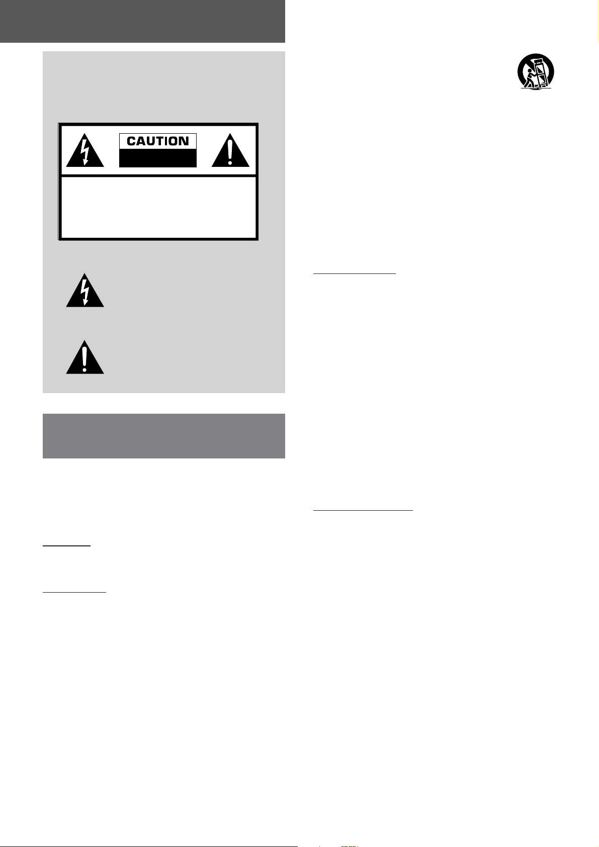
Explanation of Graphical Symbols:
The lightning flash with arrowhead symbol,
within an equilateral triangle, is intended to
alert the user to the presence of uninsulated
“dangerous voltage” within the product’s
enclosure that may be of sufficient
magnitude to constitute a risk of electric
shock to persons.
The exclamation point within an equilateral
triangle is intended to alert the user to the
presence of important operating and
maintenance (servicing) instructions in the
literature accompanying the appliance.
IMPORTANT SAFETY
INSTRUCTIONS
Read the Operating Instructions carefully and completely before
operating the unit. Be sure to keep the Operating Instructions
for future reference. All warnings and cautions in the Operating
Instructions and on the unit should be strictly followed, as well
as the safety suggestions below .
Warning
To prevent electric shock or injury , these safety instructions should
be followed in the installation, use and servicing the unit.
Installation
Attachments - Do not use attachments not recommended by
the unit manufacturer as they may result in the risk of fire, electric
shock or injury to persons.
Water and Moisture - Do not use this unit near water - for
example, near a bathtub, washbowl, kitchen sink, or laundry tub,
in a wet basement, or near a swimming pool, and the like.
Heat - Do not use this unit near sources of heat, including heating
vents, stoves, or other appliances that generate heat. It also
should not be placed in temperatures less than 5˚C (41˚F) or
greater than 35˚C (95˚F ).
Mounting surface - Place the unit on a flat, even surface.
Accessories - Do not place this unit on an unstable cart, stand,
tripod, bracket, or table. The unit may fall, causing serious injury
to a child or an adult, and serious damage to the appliance. Use
only with a cart, stand, tripod, bracket, or table recommended by
the manufacturer , or sold with the unit. Any mounting of the
appliance should follow the manufacturer ’s instructions, and
should use a mounting accessory recommended by the
manufacturer .
Portable cart - An appliance and cart combination
should be moved with care. Quick stops, excessive
force, and uneven surfaces may cause the
appliance and cart combination to overturn.
Ventilation - The unit should be situated with adequate space
around it so that proper heat ventilation is assured. Allow 10 cm
clearance from the rear and the top of the unit, and 5 cm from
the each side.
Slots and openings in the cabinet and the back or bottom are
provided for ventilation, and to ensure reliable operation of the
unit and to protect it from overheating, these openings must not
be blocked or covered. The openings should never be blocked
by placing the unit on a bed, sofa, rug or other similar surface.
This unit should not be placed in a built-in installation such as a
bookcase unless proper ventilation is provided.
Object and Liquid Entry - Never push objects of any kind into
this unit through the cabinet slots as they may touch dangerous
voltage points or short-circuit parts that could result in a fire or
electric shock. Never spill liquid of any kind on the unit.
Electric Power
Power Sources - This unit should be operated only from the
type of power source indicated on the marking label. If you are
not sure of the type of power supply to your home, consult your
appliance dealer or local power company . T o operate unit on
battery power , or other sources, refer to the operating instructions.
Grounding or Polarization - This unit is provided with a polarized
alternating-current line plug (a plug having one blade wider than
the other). This plug will fit into the power outlet only one way .
This is a safety feature. If you are unable to insert the plug fully
into the outlet, try reversing the plug. If the plug should still fail to
fit, contact your electrician to replace your obsolete outlet. Do
not defeat the safety purpose of the polarized plug.
Power-Cord Protection - Power-supply cords should be routed
so that they are not likely to be walked on or pinched by items
placed upon or against them, paying particular attention to cords
at plugs, convenience receptacles, and the point where they exit
from the product.
Overloading - Do not overload wall outlets, extension cords,
integral convenience receptacles as this can result in a risk of
fire or electric shock.
Outdoor Antenna
Power lines - An outside antenna system should not be located
in the vicinity of overhead power lines or other electric light or
power circuits, or where it can fall into such power lines or circuits.
When installing an outside antenna system, extreme care should
be taken to keep from touching such power lines or circuits as
contact with them might be fatal.
Outdoor Antenna Grounding - If an outside antenna or cable
system is connected to the unit, be sure the antenna or cable
system is grounded so as to provide some protection against
voltage surges and built-up static charges. Section 810 of the
National Electrical Code, ANSI/NFPA No.70, provides information
with regard to proper grounding of the mast and supporting
structure, grounding of the lead-in wire to an antenna discharge
unit, size of grounding conductors, location of antenna-discharge
unit, connection to grounding electrodes, and requirements for
the grounding electrode. See the figure.
2
ENGLISH
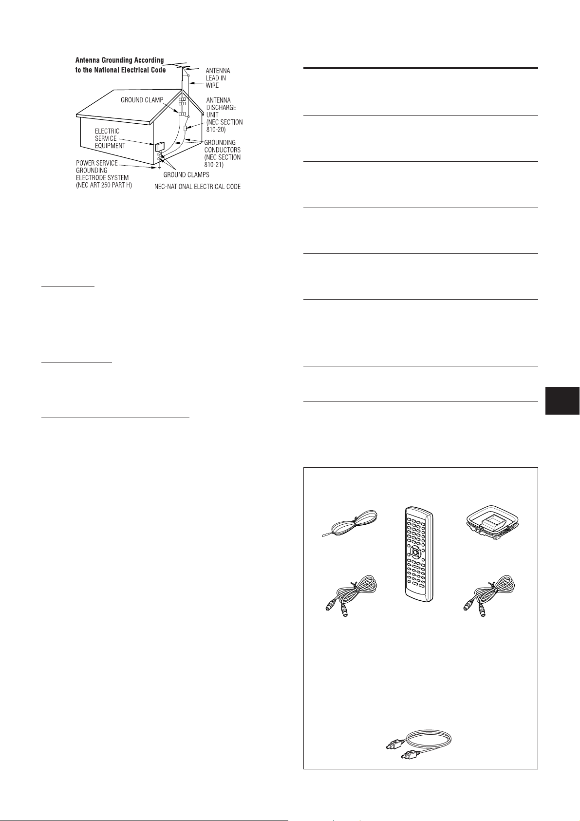
TABLE OF CONTENTS
IMPORTANT SAFETY INSTRUCTIONS ............................ 2
PREPARATIONS
CONNECTIONS .................................................................. 4
BEFORE OPERA TION........................................................8
SOUND
CUSTOM AUDIO ADJUSTMENT ....................................... 9
DSP SURROUND................................................................ 9
Note to CATV system installer:
This reminder is provided to call the CA TV system installer ’s
attention to Section 820-40 of the NEC which provides guidelines
for proper grounding and, in particular , specifies that the cable
ground shall be connected to the grounding system of the
building, as close to the point of cable entry as practical.
Lightning
For added protection for this unit receiver during a lightning storm,
or when it is left unattended and unused for long periods of time,
unplug it from the wall outlet and disconnect the antenna or cable
system. This will prevent damage to the unit due to lightning and
powerline surges.
Maintenance
Cleaning - Unplug this unit from the wall outlet before cleaning.
Do not use liquid cleaners or aerosol cleaners. Use a damp cloth
for cleaning.
Damage Requiring Service
Unplug this unit from the wall outlet and refer servicing to qualified
service personnel under the following conditions:
1) When the power cord or plug is damaged.
2) If liquid has been spilled, or objects have fallen into the unit.
3) If the unit has been exposed to rain or water .
4) If the unit does not operate normally by following the operating
instructions. Adjust only those controls that are covered by
the operating instructions as improper adjustment of other
controls may result in damage and will often require extensive
work by a qualified technician to restore the unit to normal
operation.
5) If the unit has been dropped or the cabinet has been damaged.
6) When the unit exhibits a distinct change in performance - this
indicates a need for service.
Do not attempt to service this unit yourself as opening or removing
covers may expose you to dangerous voltage or other hazards.
Refer all servicing to qualified service personnel.
Replacement Parts - When replacement parts are required, be
sure the service technician has used replacement parts specified
by the manufacturer or having the same characteristics as the
original part. Unauthorized substitutions may result in fire, electric
shock or other hazards.
Safety Check - Upon the completion of any service or repairs to
this unit, ask the service technician to perform safety checks to
determine that the unit is in proper operating condition.
BASIC OPERA TIONS
SELECTION OF AUDIO/VIDEO SOURCE.......................10
RECORDING AN AUDIO SOURCE .................................11
RADIO RECEPTION
MANUAL TUNING ............................................................. 12
PRESET TUNING .............................................................. 12
DOLBY SURROUND AND DTS SURROUND
TURNING SURROUND ON AND OFF............................. 13
SETTING SPEAKER SIZE AND DISTANCE ................... 14
ADJUSTING SPEAKER LEVEL BALANCE .................... 15
OTHER SETTINGS ........................................................... 16
TIMER
SETTING THE SLEEP TIMER .......................................... 17
GENERAL
CARE AND MAINTENANCE ............................................ 17
TROUBLESHOOTING GUIDE .......................................... 17
SPECIFICATIONS............................................................. 18
PARTS INDEX ...................................................................19
Check your accessories
FM antenna Remote control AM antenna
Video connecting cord
(AV-NW31 only)
Operating Instructions, etc.
For the customers who bought the AV-NW31 (for HT NW300 and HT-DV2300)
• For the connections and operations of the speaker system
and the DVD player , refer also to the operating instructions
supplied with the speaker system (for HT -NW300 and HTDV2300) or the DVD player (for HT -DV2300).
• The optical connecting cord is also supplied to the system
HT-DV2300).
Coaxial connecting cord
(AV-NW31 only)
En
ENGLISH
3
PREPARATIONS
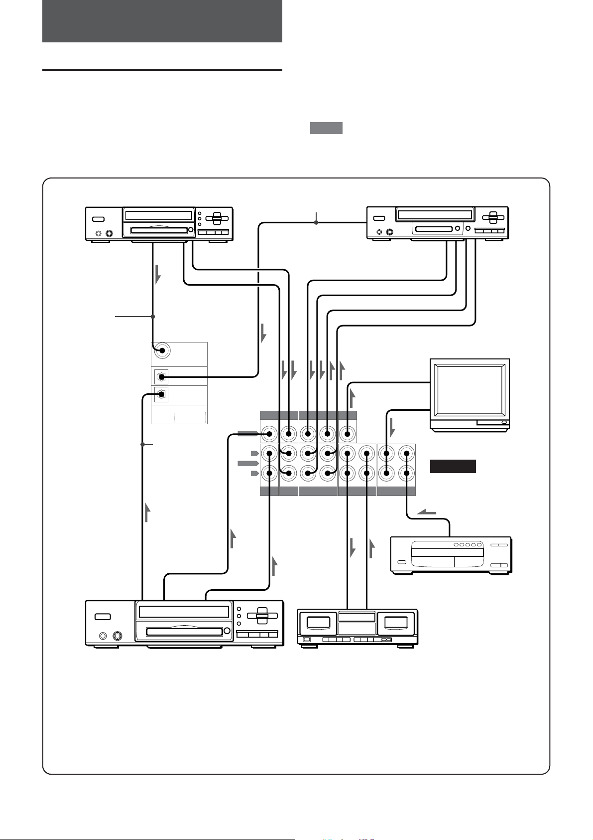
CONNECTIONS
Before connecting the AC cord
The rated voltage of your unit shown on the rear panel is 120 V
AC. Check that the rated voltage matches your local voltage.
IMPORTANT
Plug in the AC power cord to the AC outlet after all other
connections are made.
DVD, video 2*1, LD*2 or cable TV
to COAXIAL
DIGITAL OUT
to VIDEO OUT*
to AUDIO OUT
Coaxial
connecting cord
COAXIAL
(VIDEO 2)
OPTICAL
(VIDEO 1)
OPTICAL
(DVD)
DIGITAL IN
PCM
/
DOLBY DIGITAL
/ DTS
Optical
connecting cord
3
*
3
*
3
*
Optical connecting cord
to OPTICAL DIGITAL OUT
4
DVD
VIDEO
L
AUDIO
R
DVD
CONNECTING EQUIPMENT
Jacks and plugs of the connecting cord are color-coded as follows:
Red jacks and plugs: For the rigtht channel of audio signals
White jacks and plugs: For the left channel of audio signals
Yellow jacks and plugs: For video signals
NOTE
Insert the plugs fully into the jacks. Loose connections may
produce a humming sound or other noise interference.
VIDEO 2
VIDEO 1 / MD
/
LD / TV
ININININININOUT
VIDEO 2
/
LD / TV
OUT IN IN INOUT
VIDEO 1 / MD
Video 1*1 or MD player
to VIDEO OUT (V ideo 1)
to AUDIO OUT
to VIDEO IN (Video 1)
to AUDIO IN
to VIDEO IN
to AUDIO OUT
MONITOR
VIDEO OUT
TAPE AUX CD
TV
REAR
to OPTICAL
to VIDEO OUT*
4
DIGITAL OUT
to AUDIO OUT
DVD player
*1When connecting a monaural video, use a stereo-mono
connecting cord (not supplied).
*2When connecting an LD player equipped with the AC-3 RF OUT
terminal, use an RF demodulator unit. Also connect the analog
AUDIO OUT terminals of the LD player to the receiver to play
all the sources. For further information, refer to the instructions
of the LD player .
4
ENGLISH
CD player
to LINE OUT
to LINE IN to LINE OUT
Tape deck
Signal stream
u
*3Input sound through the DIGIT AL IN terminals (COAXIAL
(VIDEO 2), OPTICAL (VIDEO 1) and OPTICAL (DVD)) cannot
be recorded. When recording the sound from the DVD, CD, MD
or LD player , connect the analog AUDIO OUT terminals of the
player to the corresponding AUDIO IN terminals of the receiver .
*4With this connection, the picture noise may appear when playing
copy protected DVDs. In this case, it is recommended to connect
the VIDEO OUT terminal of the DVD player directly to a TV set,
not through the receiver .
IMP: 8Ω
C
E
N
T
E
R
S
P
E
A
K
E
R
IMP: 8
Ω
S
U
R
R
O
U
N
D
S
P
E
A
K
E
R
S
R
L
IMP: 8
Ω
F
R
O
N
T
S
P
E
A
K
E
R
S
RL
IMP: 8
Ω
F
R
O
N
T
S
P
E
A
K
E
R
S
RL
1 and 2 in the illustration correspond to the following details.
2FM antenna
1Sub woofer
Right Left
1Surround speakers
2AM antenna
1Front speakers
Right Left
PREPARATIONS
1Center speaker
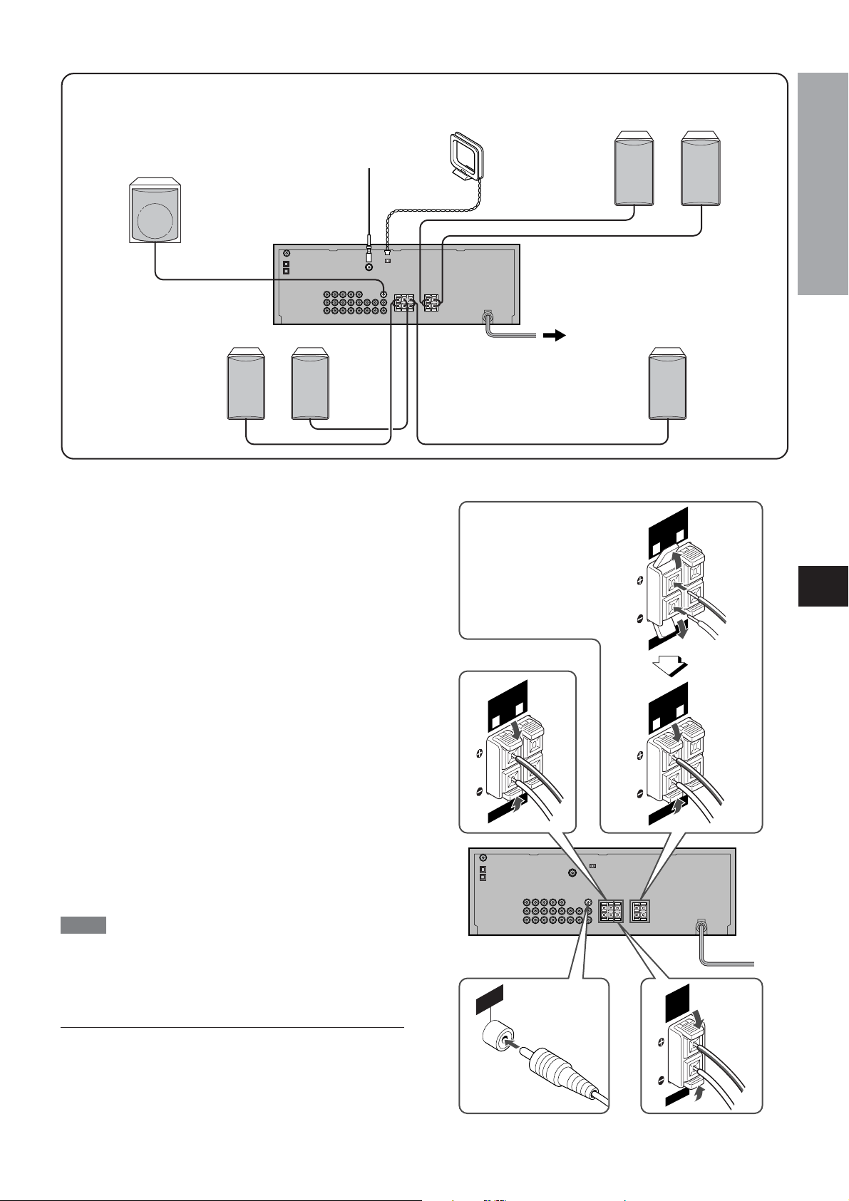
CONNECTING SPEAKERS
11
1
11
Speaker terminals
Connect front speakers, a center speaker , surround speakers
and a sub woofer to the corresponding speaker terminals on the
unit:
- the front speaker cords to the FRONT SPEAKERS terminals
- the center speaker cord to the CENTER SPEAKER terminals
- the surround speaker cords to the SURROUND SPEAKERS
terminals
- the sub woofer (with a built-in amplifier) cord to the SUB
WOOFER jack, for more powerful bass sounds
- When not connecting the sub woofer, be sure to select
“SUBW OFF” (sub woofer of f) mode (see the next page).
- When not connecting the center speaker and/or surround
speakers, and regarding to the size of speakers (including
front speakers), speaker settings must be done. Before using
the unit, be sure to make speaker settings in accordance with
your speaker configuration (see page 14).
Speaker impedance
For all speakers, use speakers of 8 ohms or more.
++
++
--
Connecting
+ to
++
+,
++
- to
--
--
- terminals
--
To get the proper sound ef fect, the speaker terminals on the unit
and the speaker should be connected with proper polarity; the
+ terminal on the unit should be connected to the + terminal on
the speaker (and - to -).
Front speakers
Lift up the terminal flap,
insert the speaker cord
lead into the terminal slot,
then close the flap. Check
that the cord is connected
securely .
Surround speakers
En
NOTE
• Be sure to connect the speaker cords correctly as shown in the
illustration on the right column. Improper connections can cause
short circuits in the SPEAKER(S) terminals.
• Do not leave objects generating magnetism near the speakers.
Do not put any equipment such as DVD players and speakers on
the receiver to assure proper heat ventilation.
R
B
E
U
F
S
O
O
T
W
U
O
Sub woofer
Center speaker
ENGLISH
5

POSITIONING THE SPEAKERS
Position the speakers to make the most of Dolby , DTS or DSP
surround ef fect.
Front speaker (L/R)
Center speaker (C)
Position in the center of the two front speakers. In addition,
position on or below the TV set, if connecting a TV set to the
unit.
Surround speakers (LS/RS)
Place the surround speakers directly to the side of or slightly
behind the listening area. Align them horizontally , about 1 meter
(3.2 feet) above ear height.
Sub woofer (SW)
Place the sub woofer in any place near the two front speakers.
When not connecting the sub woofer
Select the “ SUBW OFF” mode.
1 Press and hold SPEAKERS until “ FR LARGE” is displayed.
2Within 6 seconds, turn MUL TI JOG so that “ SUBW ON” is
displayed.
3 Press ENTER.
4Within 6 seconds, turn MUL TI JOG so that “ SUBW OFF” is
displayed, then press ENTER.
CONNECTING THE SUPPLIED
ANTENNAS
Connect the FM antenna to the FM 75 Ω terminal and the AM
antenna to the AM LOOP jack.
(CO
To stand the AM loop antenna on a surface
Fix the claw to the slot as shown in the illustration.
22
2
22
FM antenna
AM antenna
OP
LO
AM
TENNA
AN
Ω
75
FM
AXIAL)
Turning on/off the front speakers
Each time you press SPEAKERS on the front panel, the front
speakers are turned on and of f. When the front speakers are
turned on, “ SP3” lights up on the display window .
NOTE
• When you turn of f the front speakers, the surround mode (Dolby
Digital, Dolby Pro Logic or DTS) or the DSP mode will be
canceled.
• When the front speakers are turned of f, SURROUND and DSP
on the front panel cannot be used. (“ CAN’T USE” will be
displayed).
To position the antennas
Keep antennas away from metallic objects, electrical equipment
(including the unit itself) and cords.
FM antenna: Extend fully and position for the best reception. If
reception is poor , connect an optional outdoor antenna to the
FM 75Ω terminal.
AM antenna: Rotate to find best reception.
6
ENGLISH

ABOUT THE REMOTE CONTROL
Inserting batteries
Detach the battery cover on the rear of the remote control and
insert two R6 (size AA) batteries.
Selecting equipment to be controlled
To control video recorders, press either VIDEO 1 or VIDEO 2,
whichever allows you to control correctly the video recorder .
To control a TV , press TV.
To control a DVD player , press DVD.
To control a CD player , press CD.
• There are two sets of transmitted codes for CD, VIDEO 1 and
VIDEO 2.
To change the code set for CD, hold down CD and press 0,0,1
or 0,0,2. (When you choose 0,0,2, you can also operate a DVD
player with the remote control.)
To change the code set for VIDEO 1 and VIDEO 2, hold down
VIDEO 1 or VIDEO 2 respectively and press 4,0,0 or 5,3,3.
PREPARATIONS
• Replace the batteries with new ones when the operational
distance between the remote control and the main unit becomes
shorter .
• Remove the batteries if the unit is not going to be used for an
extended period of time.
• The remote control may not operate if it is used under intense
sunlight or if its line of sight is obstructed.
Important
ENTER on the remote control substitutes for ENTER on
the main unit when the function is TUNER. In other
functions, this button is mainly for operating the DVD player
(see the right column).
To select the function with the remote control
Press FUNCTION repeatedly . The function changes cyclically .
Operating AIWA equipment with the remote control
You can control the basic functions of AIWA video recorder , TV ,
DVD player or CD player with the remote control.
Note that there are models that cannot be operated with the
remote control.
VIDEO1,
VIDEO2,
TV,DVD,
CD
SHIFT
TUNER
To control the receiver (this unit)
Press TUNER.
NOTE
Be sure to press TUNER before operating the receiver (this unit).
Operating video recorders
Press the following buttons.
c - Starts playback.
a - Pauses playback.
s - Stops playback.
f, g - Fast rewind/fast forward
TV/VIDEO - Switches between the TV mode and VIDEO mode.
POWER - Turns on/of f the power .
0-9, +10 - Selects channel.
G/F or k/i - Channel down/up.
C - Resets the counter .
t/r - Skip forward/back to the next/previous scene.
Operating TVs
Press the following buttons.
TV/VIDEO - Switches between the TV mode and VIDEO mode.
POWER - Turns on/of f the power .
0-9, +10 - Selects channel.
k/i - Channel down/up.
j/l - Decrease/increase volume.
Operating DVD players
Press the following buttons.
POWER - Turns on/of f the power .
c - Starts playback.
a - Pauses playback.
s - Stops playback.
f,g - Searches for a track.
r,t - Skips a track.
G,F while pressing SHIFT - Enters slow playback mode.
AUDIO while pressing SHIFT - Selects the sound tracks.
SUB TITLE while pressing SHIFT - Changes the subtitle
language.
ANGLE while pressing SHIFT - Changes the picture angle.
ON SCREEN while pressing SHIFT - Displays On Screen Display
menu.
ZOOM while pressing SHIFT - Zooms in the picture.
PRGM while pressing SHIFT - Enters the programmed play mode.
RANDOM while pressing SHIFT - Enters the random play mode.
REPEAT while pressing SHIFT - Enters the repeat play mode.
TOP MENU - Displays the title menu.
MENU - Displays menu programs.
i,k,j,l - Moves the cursor to select a program, etc.
ENTER - Executes or fixes the selected item from a menu.
v RETURN - Exits the setup menu screen.
SET UP - Displays the setup menu.
En
ENGLISH
7

SPEAKERS
DIMMER
PHONES SHIFT
POWER
6STANDBY/ON
POWER
DISPLAY
Operating CD players
Press the following buttons.
POWER - Turns on/of f the power .
c - Starts playback.
a - Pauses playback.
s - Stops playback.
f,g - Searches for a track.
r,t - Skips a track.
0-9, +10 - Selects a track.
PRGM while pressing SHIFT - Enters the programmed play mode.
RANDOM while pressing SHIFT - Enters the random play mode.
REPEAT while pressing SHIFT - Enters the repeat play mode.
NOTE
There are some AIWA models that cannot be operated with the
remote control, or for which some of the functions of the remote
control do not work.
BEFORE OPERATION
To turn the unit on
Press POWER
The STANDBY/ON indicator lights in green.
Operation is possible after four seconds. The volume level or
function name is displayed one after the other for the first four
seconds.
66
6ST ANDBY/ON (POWER).
66
To change the brightness level of the display
Press DIMMER (hold down SHIFT and press
DISPLA Y) repeatedly.
The dimmer mode changes as follows.
DIM-OFF
DIM-OFF: The normal display
DIMMER 1: The illumination of the display is dimmer than usual.
DIMMER 2: The illumination of the display is dimmer .
DIMMER 3 (no display): Everything on the display is cleared.
NOTE
While in the mode other than DIM-OFF , if you operate the receiver ,
the display illuminates at the DIM-OFF level, and after 6 seconds,
the display brightness returns to the level previously set.
Note that “DIMMER” is displayed for one second before everything
is cleared when the previously set level is “no display”.
Using the headphones
Connect headphones with a standard stereo plug (ø6.3 mm, 1/4
inch) to the PHONES jack. Be sure to turn of f the speakers by
pressing SPEAKERS. Otherwise sound is output from the
speakers.
DIMMER 1 DIMMER 2
DIMMER 3 (No display)
8
ENGLISH
To turn the unit off, press POWER 6STANDBY ON (POWER).
The STANDBY/ON indicator turns to red.

SOUND
CUSTOM AUDIO ADJUSTMENT
MASTER VOLUME
BALANCE MUTING
MULTI JOG
BASS
TREBLE
VOLUME CONTROL
Turn MASTER VOLUME (press VOLUME +,-).
Adjust from 0 (minimum) to 49 and MAX (maximum).
Volume level setting is retained during power-of f standby . If the
unit is turned of f with the volume set to 21 or higher , it is
automatically turned down to 20 the next time the unit is turned
on.
JOG
+,-
TONE
VOLUME
+,-
BALANCE
MUTING
DSP SURROUND
MULTI JOG
DSP
The DSP (Digital Signal Processor) surround circuits can recreate
the effect of sounds reflected from walls or ceilings, to obtain the
sound presence of real environments. The unit provides 5 DSP
preset modes.
1 Press DSP.
2Within 6 seconds, turn MULTI JOG to select the
desired DSP mode.
The “ DSP” and “ S” (surround speakers) indicators light up.
DISCO HALL LIVE CHURCH MOVIE
JOG
+,-
DSP
SOUND
Left and right balance of the front and surround speakers
1 Press BALANCE repeatedly .
“L/R 0dB” and “ LS/RS 0dB*” appear alternately .
“L/R 0dB” means that the left and right front speakers level is
the same.
“LS/RS 0dB*” means that the left and right surround speakers
level is the same.
Select one of them to adjust it.
* This is not displayed in stereo mode (SURROUND of f or
DSP off) or when the surround speakers are set to “ NONE”.
2Turn MULTI JOG (press JOG +,- repeatedly).
Example:
“L>R 5dB” means that the left front speaker level is 5 dB higher
than that of the right front speaker .
“LS<RS 10dB” means that the right surround speaker level is
10 dB higher than that of the left surround speaker .
NOTE
• The adjustable level ranges from 0 to 10 dB.
• The surround speaker balance can be adjusted only when
SURROUND or DSP is set to on and the surround speakers
are not set to “ NONE”.
Muting the sound temporarily
Press MUTING so that “ MUTE ON” appears on the display . The
sound is muted.
To return to the previous volume level, press MUTING again.
“MUTE OFF” is displayed.
To reset the volume and balance to the default value, press and
hold BALANCE until “ LVL RESET” is displayed.
All the speaker volume as well as the left and right balance of
the front and surround speakers are reset to the default value (0
dB).
When the music source is monaural
The DSP system may not work ef fectively depending on the DSP
mode selected.
To cancel the selected mode
Press DSP to display the DSP mode name, and press the button
again within 6 seconds. “ DSP OFF” appears on the display .
To select with the remote control
1 Press DSP.
2Within 6 seconds, press JOG + or - repeatedly until the
desired DSP mode is displayed.
NOTE
• DSP cannot be turned on when the surround speakers are set
to “ NONE”.
• DSP is automatically canceled when SURROUND is turned
on, and vice versa.
SOUND ADJUSTMENT DURING
RECORDING
The output volume and tone of the speakers or headphones may
be freely varied without af fecting the level of the recording.
En
BASS AND TREBLE
Turn BASS or TREBLE.
The adjustable level for the bass sound and the treble sound
ranges from –10 to +10 dB at 2 dB steps.
Adjusting bass and treble with the remote control
1 Press TONE repeatedly to select BASS or TREBLE.
2Press JOG + or - to adjust the bass or treble level.
ENGLISH
9

BASIC OPERATIONS
SELECTION OF AUDIO/VIDEO
SOURCE
FUNCTION
ENTER
TUNING
INPUT MODE
1Turn FUNCTION to select the program source.
The function changes in the following order .
FM AM DVD CD
The actual source selected (except FM and AM) depends on
the equipment connected to the input terminals on the rear
panel of the unit.
For example, if an MD player is connected to the VIDEO 1/
MD terminals, select VIDEO 1 to listen to the MD playback
sound.
To select with the remote control
Press FUNCTION repeatedly .
2Start the selected program source.
3 Adjust the sound.
FUNCTION
JOG +,-
TV/VIDEO
INPUT
MODE
AUXTAPEVIDEO 1VIDEO 2
SELECTION OF VIDEO SOURCE
While selecting a program source which does not contain video
input (such as a CD player), you can select a video source
separately to be viewed on the TV .
1 Press FUNCTION repeatedly to select FM, AM, CD,
AUX or T APE.
2 Press TV/VIDEO.
++
3 Press JOG
The video source to be output through the MONIT OR VIDEO
OUT jack changes in the following order .
M-OUT V1 M-OUT V2 M-OUT D VD
M-OUT V1: Video image of the equipment connected to the
VIDEO 1/MD terminals can be viewed on the TV.
M-OUT V2: Video image of the equipment connected to the
VIDEO 2/LD/TV terminals can be viewed on the TV .
M-OUT DVD: Video image of the equipment connected to the
DVD terminals can be viewed on the TV.
--
+,
- repeatedly.
++
--
TO CHANGE A DISPLAYED NAME FOR
THE VIDEO 1 AND VIDEO 2 FUNCTION
When the VIDEO 1 function is selected, VIDEO 1 is displayed
initially . It can be changed to MD.
While pressing ENTER, press INPUT MODE.
The displayed name for the VIDEO 2 function can be changed to
VIDEO 2, LD or TV . Select VIDEO 2 function.
While pressing ENTER, press INPUT MODE.
TO SELECT “ANALOG” OR “DIGIT AL”
MODE OF THE DVD, VIDEO 1 OR VIDEO 2
FUNCTION
Press INPUT MODE when the DVD, VIDEO 1 or VIDEO 2 function
is selected. The selected mode “ ANALOG” or “ DIGITAL” appears
on the display .
In DIGITAL mode: Equipment connected to the DIGIT AL IN
OPTICAL (DVD) terminal is selected as a source for the DVD
function, equipment connected to the DIGIT AL IN OPTICAL
(VIDEO 1) for the VIDEO 1 function, and equipment connected
to the DIGITAL IN COAXIAL (VIDEO 2) for the VIDEO 2 function.
In ANALOG mode: Equipment connected to the DVD terminals
is selected as a source for the DVD function, equipment
connected to the VIDEO 1/MD for the VIDEO 1 function, and
equipment connected to the VIDEO 2/LD/TV for the VIDEO 2
function.
10
ENGLISH

FUNCTION
FUNCTION
INPUT MODE
WHEN THE “OVER LEVEL” INDICA TOR
LIGHTS UP
When input analog signals from the connected equipment are
too high to accept, the OVER LEVEL indicator lights up. In this
case, adjust the input level so that the indicator disappears.
To lower the sound level of the connected source
When the analog sound level of the connected source is higher
than that of the FM and AM functions, adjust it as follows.
RECORDING AN AUDIO SOURCE
1 Select the function to be adjusted.
Turn FUNCTION and play the source.
2 Press TUNING
The level is decreased as follows.
0 dB –6 dB –12 dB
To restore the previous level, press TUNING N repeatedly .
•When the analog output of the CD player or DVD player is 2
Vrms, set the level to –6 dB.
MM
M repeatedly.
MM
1 Select the program source to be recorded.
Turn FUNCTION (or press FUNCTION repeatedly).
2 Set the tape deck or MD recorder to recording
mode.
3Start the selected program source.
NOTE
• Any sound control system has no ef fect on recording (see page
9).
• Input sound through the DIGIT AL IN terminals cannot be
recorded. When recording the sound from the DVD, CD, MD or
LD player , connect the analog AUDIO OUT terminals of the
player to the corresponding AUDIO IN terminals of the receiver .
The sound will be recorded in 2 ch stereo.
• Input sound from the tape deck connected to the TAPE IN
terminals cannot be recorded.
BASIC OPERA TIONS
En
ENGLISH
11

RADIO RECEPTION
MANUAL TUNING
ENTER
MULTI JOG
TUNING
INPUT MODE
POWER
FUNCTION
6STANDBY/ON
1Turn FUNCTION to select the desired band; FM
or AM.
NN
2 Press TUNING
Alternatively , press j or l on the remote control.
“TUNE” is displayed when a station is tuned in.
“1” is displayed for FM stereo reception.
To search for a station automatically (Auto search)
Hold down TUNING N or M (or j or l).
The unit searches for a station and stops at reception.
To stop the search manually , press TUNING N or M (or j or
l).
• Auto search may not stop at stations with weak signals.
When an FM stereo broadcast contains noise
Hold down SHIFT and press TUNER MODE on the remote control
so that “ MONO” is displayed.
Noise is reduced, although reception is monaural.
To cancel, repeat the above so that “ STEREO” is displayed.
MM
N/
M to tune in a station.
NN
MM
0-9,+10
TUNER
MODE
C
i/k/j/l
ENTER
SHIFT
PRESET TUNING
You can preset up to 32 stations and tune them in directly .
PRESETTING ST ATIONS
1Tune in the desired station.
2 Press ENTER to store the station.
The preset number , beginning from “ 1” appears on the display .
3 Repeat steps 1 and 2 to store other stations.
The next station will not be stored if a total of 32 preset stations
have already been stored. (“ FULL” is displayed.)
TUNING IN PRESET STATIONS
1Turn FUNCTION to select FM or AM.
2Turn MULTI JOG to select a preset number.
Alternatively , press i or k on the remote control.
You can tune in the desired preset station directly by pressing
the numbered buttons on the remote control.
-To select preset number 1 1, press +10 and 1.
-To select preset number 25, press +10, +10 and 5.
To clear a preset station
1Tune in the station by preset tuning.
2 Press ENTER, and press ENTER again while the frequency
flashes on the display .
Alternatively , press ENTER or C on the remote control, and
press ENTER while the frequency flashes on the display .
RADIO RECEPTION
En
When the reception contains noise interference
Move the unit away from other electrical appliances, especially
digital audio devices, or turn of f the appliances that generate
noise signals.
To switch the AM tuning interval
The default setting of the AM tuning interval is 10 kHz/step. If
you use this unit in an area where the frequency allocation system
is 9 kHz/step, change the tuning interval.
Hold down INPUT MODE and press POWER 6STANDBY/ON.
To reset the interval, repeat this procedure.
NOTE
When the AM tuning interval is changed, all preset stations are
cleared. The preset stations have to be set again.
ENGLISH
12

2chSTEREOPRO LOGIC
DOLBY SURROUND AND DTS SURROUND
This unit is equipped with the Dolby Pro Logic decoder , Dolby
Digital decoder and DTS decoder .
The unit and the center and surround speakers (standard) assure
full-scale home theater sound. When playing back discs or video
software that have been recorded in Dolby Pro Logic, Dolby Digital
surround or DTS surround, astonishingly realistic sound
surrounds the listener to create a new level of audio/visual
entertainment.
Independent control of the five channels allows the listener to
enjoy the same type of sound reproduction experienced in movie
theaters. V oices are reproduced in the front and center sound
field, while ambient sounds like cars and crowds are reproduced
on all sides of the listener for an incredibly lifelike audio/video
experience.
TURNING SURROUND ON AND
OFF
SURROUND
INPUT
MODE
SURROUND
FUNCTION
INPUT MODE
Check the followings:
• Before enjoying Dolby surround or DTS surround, set the
speaker existance, size and distance (see page 14), and
adjust the speaker sound levels to the proper balance (see
page 15).
•Make sure the speakers are properly connected and positioned
(see pages 5 and 6).
• Make sure the TV set and video unit are properly connected
(see page 4).
• Make sure the disc and video tape, etc., support Dolby Pro
Logic, Dolby Digital surround or DTS surround.
•When connecting an LD player equipped with the AC-3 RF OUT
terminal, use an RF demodulator unit. Also connect the analog
AUDIO OUT terminals of the LD player to the receiver to play
all the sources. For further information, refer to the instructions
of the LD player .
4 Press SURROUND.
Pressing the button changes the surround mode according to
the type of the input signal, as follows.
In case Dolby Digital or DTS multichannel source is input:
DOLBY D or DTS 2chSTEREO
In case Dolby Digital 2-channel source or other source is input:
The following indicators light according to the input signal and
other conditions.
hDIGITAL : Dolby Digital signal is input.
dts : DTS source signal is input.
hPRO LOGIC : 2-channel source is played with surround set
to on.
If you feel that the surround effect is not sufficient
Surround playback is af fected by many factors. Check the
following points.
• Are settings made correctly according to the connected
speakers and their position?
• Is the DVD digital out signal correctly selected?
• In Dolby Digital and DTS, there are multi-sources other than
5.1ch. Confirm the type of the source being played.
•A disc may contain multiple audio tracks. Confirm the audio
track being played.
• Dolby Digital and DTS sources can be enjoyed only when
connections are made in digital.
NOTE
• This unit supports input signals of the Dolby Digital surround
bit stream, DTS surround bit stream and linear PCM whose
sampling frequency is 32 kHz, 44.1 kHz and 48 kHz.
• When connecting some DVD players to the receiver through
the digital in terminals, noise may be heard in the DVD operation:
e.g. searching a disc, skipping a chapter .
SURROUND
DOLBY SURROUND AND DTS
En
1Turn FUNCTION to select a function.
2 Press INPUT MODE to select “DIGITAL” or
“ANALOG”.
Select in accordance with the connected equipment and sound
source to be played.
3Play the surround source by the connected
equipment.
ENGLISH
13

SETTING SPEAKER SIZE AND
DISTANCE
ENTER
MULTI JOG
SPEAKERS
Set the speaker size (large or small) and the speaker distance
(distance between the speaker and the listening position), as
well as speaker existance, correctly as described below .
Selectable sizes and distances
[Front speakers]
“LARGE” : larger size
“SMALL” : smaller size
[Center speaker]
“LARGE” : larger size
“SMALL” : smaller size
“NONE” : no center speaker
[Surround speakers]
“LARGE” : larger size
“SMALL” : smaller size
“NONE” : no surround speakers
LARGE : Frequencies (sounds) over all the band of the
channel is output.
SMALL : Frequencies (sounds) under 90 Hz are not output.
They are re-directed to the sub woofer or other large speakers.
Default settings
Default settings of the speaker size and distance are as follows:
[AV-NW30]
“FR LARGE” (Front speakers are large.)
“C LARGE” (Center speaker is large.)
“SUR LARGE” (Surround speakers are large.)
[AV-NW31]
“FR SMALL” (Front speakers are small.)
“C SMALL” (Center speaker is small.)
“SUR SMALL” (Surround speakers are small.)
[Common]
“SUBW ON” (Sub woofer is turned on.)
“FR 17FT” (Distance between the left and right front speakers
and the listening position is 17 feet.)
“C 17FT” (Distance between the center speaker and the listening
position is 17 feet.)
“SUR 12 FT” (Distance between the left and right surround
speakers and the listening position is 12 feet.)
NOTE
• When “ FR SMALL” is selected, “ SUBW ON” is selected
automatically .
When the front speakers are small, be sure to connect the sub
woofer; otherwise the bass sound will not be emitted.
• When “ FR SMALL” is selected, “ C LARGE” and “ SUR LARGE” cannot
be selected.
First make sure that “ BY-PASS ON” is not set for DTS.
[Sub woofer]
“ON” : sub woofer activated
“OFF” : sub woofer deactivated or no sub woofer
[Distance between the front sepakers and the listening
position]
From “ 1” foot to “ 30” feet with 1 foot step
[Distance between the center speaker and the listening
position]
From “ 1” foot to “ 30” feet with 1 foot step
[Distance between the surround speakers and the
listening position]
From “ 1” foot to “ 30” feet with 1 foot step
NOTE
• When setting the speaker distance, first set the front speakers
distance. The center speaker distance then can be set between
the distance equal to the front speaker distance and the distance
5 feet shorter than the front speaker distance. Also, the surround
speakers distance can be set between the distance equal to
the front speaker distance and the distance 15 feet shorter than
the front speaker distance.
• Adjust the center speaker distance so that the voices are heard
from the center position.
• Adjust the surround speakers distance freely acording to your
preference.
• When the front speakers distance is changed, the center and
surround speakers distance may automatically be modified.
1 Press and hold SPEAKERS until “FR LARGE” is
displayed.
2Within 6 seconds, turn MUL TI JOG.
The adjustable items are displayed cyclically as follows:
FR LARGE(SMALL)
C LARGE(SMALL) SUR LARGE(SMALL)
C 17FTSUR 12FT
FR 17FT
SUBW ON
3 When the item to be adjusted is displayed, press
ENTER.
The adjustable size (or distance) flashes.
4Within 6 seconds, turn MULTI JOG to adjust the
size (or distance), and press ENTER.
14
ENGLISH

ADJUSTING SPEAKER LEVEL
BALANCE
BALANCE
JOG +,-
MANUAL
SELECT
SUBWOOFER
+,-
CENTER
+,-
REAR +,-
BALANCE
4 Press MANUAL SELECT again to stop the noise
signal.
NOTE
• When the noise signal cycles through all the speakers for ten
times, the noise singal stops automatically .
• When the center speaker and/or surround speakers are set to
“NONE”, their level balance cannot be adjusted. (“ C 0dB” and “ S
0dB” are not displayed.)
About the channels
The left and right front speakers create the stereo ef fect.
The center speaker helps precise sound positioning over a broad
sound field.
The surround speakers enhance the “depth” of the sound field.
CHANGING SPEAKER VOLUME
TEMPORARILY
SURROUND
DOLBY SURROUND AND DTS
The unit is equipped with a built-in test signal generator called a
noise sequencer for easy balance adjustment of all five channels.
The sequencer outputs a noise signal that “travels” from channel
to channel, enabling the simple adjustment of sound level to
achieve the same apparent loudness, at your listening position,
from each channel.
Preparation
• Before adjusting the speaker level balance, be sure to set
the speaker size, distance and existance correctly.
• Before adjusting the speaker level balance, turn of f the DSP
surround system.
•Operate the unit while playing the source recorded in Dolby
Digital surround or Dolby Pro Logic.
1Turn SURROUND on.
2 Press and hold MANUAL SELECT on the remote
control until “L” of “L/R 0dB” starts to flash.
A noise signal is sent to each channel in turn at the interval of
2 seconds as follows:
L/R 0dB
C 0dB
L/R 0dB
(Left front speaker)*
(Center speaker)
(Right front speaker)*
According to the software played or your preference, you can
change the sub woofer , center speaker and surround speakers
volume temporarily .
Press SUBWOOFER +/-, CENTER +/- or REAR +/-
on the remote control.
Each speaker level can be changed within the range from –10
dB to +10 dB at 1 dB steps.
To restore the volume and balance to the default value
Press and hold BALANCE until “LVL RESET” is displayed.
All the speaker volume as well as the left and right balance of
the front and surround speakers are reset to the default value
(0 dB).
En
S 0dB
(Right surround speaker)
(Left surround speaker)
S 0dB
*L or R flashes to indicate one of the front speakers from
which the noise signal is output.
3 Adjust the sound level of the center and surround
speakers.
While “ C” or “ S” flashes in the display , press JOG + or - on
the remote control so that the sound level of the center or
surround speakers matches that of the front speakers.
The blance of the front speakers can be adjusted as well while
“L/R” is displayed.
ENGLISH
15

OTHER SETTINGS
ENTER
MULTI JOG
ADJUSTING LOW FREQUENCY SOUND
EFFECT (LFE)
The disc recorded in Dolby Digital surround contains special
signals called LFE to enhance low frequency sound ef fect.
The LFE signals are recorded in some particular parts on the
disc and output from the connected sub woofer to reproduce
astonishingly powerful low sound.
The sound level of the LFE signals can be adjusted according to
your speakers.
JOG +,-
MID NIGHT
MANUAL
SELECT
SHIFT
TO LISTEN TO THE ORIGINAL DTS
SOUND
When “ dts” appears on the display , all the sound settings can be
canceled.
Preparation
Play a disc recorded in DTS surround.
1 Press ENTER.
“BY-PASS OFF” is displayed.
2Press ENTER again so that “BY-PASS ON” is
displayed.
To restore the sound settings
Repeat steps 1 and 2 so that “ BY-PASS OFF” appears.
To operate with the remote control
Hold down SHIFT and press MID NIGHT repeatedly .
Preparation
Play a disc recorded in Dolby Digital surround.
1 Press MANUAL SELECT on the remote control.
“LFE” is displayed.
2 Press JOG + or - to adjust the LFE level.
The unit is initially set to 0 dB (maximum) and can be adjusted
as follows:
OFF –10 dB –5 dB 0 dB
MULTI JOG on the unit is also available.
When selecting “ SUBW OFF”, the LFE signals are redistributed to
other speakers.
ADJUSTING DYNAMIC RANGE
Dynamic range of the sound can be adjusted. The unit is initially
set to “ STD” (standard) mode.
Preparation
Play a disc recorded in Dolby Digital surround.
1 Hold down ENTER (hold down SHIFT and press
MID NIGHT).
“MID NIGHT THEATER” runs through on the display .
2Turn MULTI JOG (press JOG + or -) to select
“MIN”, “MAX” or “STD”.
MIN: You can enjoy the full dynamic range of sound like in the
movie theater .
STD: Original position, when playing back in home, that is
recommended by the software producers.
MAX: Select this mode when playing back at low volume.
16
ENGLISH

TIMER GENERAL
SETTING THE SLEEP TIMER
MULTI JOG
The unit can be automatically turned of f at a specified time.
1 Hold down SHIFT and press SLEEP on the remote
control.
“SLEEP” is displayed.
2Within 6 seconds, press JOG
++
+ or
++
to set the sleep timer duration.
With each press, the timer duration changes in 5-minute steps
between 5 to 240 minutes. If there is no button input for 6
seconds, the current setting is entered automatically .
The unit turns of f after the selected time.
• MULTI JOG on the unit is also available.
To check the remaining time until the unit turns off
Hold down SHIFT and press SLEEP on the remote control.
The remaining time is displayed for 6 seconds.
To cancel the sleep timer
Hold down SHIFT and press SLEEP on the remote control
repeatedly so that “ SLEEPoFF” is displayed.
SLEEP
JOG +,-
SHIFT
--
- repeatedly
--
CARE AND MAINTENANCE
Occasional care and maintenance of the unit is needed to
optimize the performance of your unit.
To clean the cabinet
Use a soft dry cloth.
If the surfaces are extremely dirty , use a soft cloth lightly
moistened with mild detergent solution. Do not use strong
solvents, such as alcohol, benzine or thinner as these could
damage the finish of the unit.
TROUBLESHOOTING GUIDE
If the unit fails to perform as described in these Operating
Instructions, check the following guide.
GENERAL
There is no sound.
• Is the AC cord connected properly?
• Is there an incorrect connection? ( ➞ pages 4-6)
• There may be a short circuit in the speaker terminals.
➞ Disconnect the AC cord, then correct the speaker
connections.
•Was an incorrect function selected?
• Is SPEAKER set correctly? ( ➞ page 8)
Sound is emitted from one speaker only.
• Is BALANCE set appropriately?
• Is the other speaker disconnected?
Sound is heard at a very low volume.
• Has MUTING been pressed?
An erroneous display or a malfunction occurs.
➞ Reset the unit as stated below .
TUNER SECTION
There is constant, wave-like static.
• Is the antenna connected properly? ( ➞ page 6)
• Is the FM signal weak?
➞ Connect an outdoor antenna.
The reception contains noise interference or the sound is
distorted.
• Is the system picking up external noise or multipath distortion?
➞ Change the orientation of the antenna.
➞ Move the unit away from other electrical appliances.
TIMER
GENERAL
En
To reset
If an unusual condition in the display window or malfunction
occurs, reset the unit as follows:
1 Press POWER 6ST ANDBY/ON to turn of f the power .
2 Press POWER 6STANDBY/ON while pressing ENTER.
Everything stored in memory after purchase is canceled.
If the power cannot be turned of f in step 1 because of a
malfunction, disconnect the AC cord, and reconnect the AC cord
after several seconds. Then carry out step 2.
ENGLISH
17

GENERAL
SPECIFICATIONS
FM tuner section
Tuning range 87.5 MHz to 108 MHz
Usable sensitivity 13.2 dBf
(IHF)
Antenna terminal 75 ohms (unbalanced)
AM tuner section
Tuning range 530 kHz to 1710 kHz (10 kHz step)
531 kHz to 1602 kHz (9 kHz step)
Usable sensitivity 350 µV/m
Antenna Loop antenna
Amplifier section
Power output Front
100 W + 100 W (1 kHz, T.H.D. less than
0.9%, 8 ohms)
120 W + 120 W (1 kHz, T.H.D. less than
10%, 8 ohms)
75 W + 75W (20 Hz – 20 kHz, T.H.D. less
than 0.9%, 8 ohms)
Rear (surround)
100 W + 100 W (1 kHz, T.H.D. less than
0.9%, 8 ohms)
120 W + 120 W (1 kHz, T.H.D. less than
10%, 8 ohms)
75 W + 75W (20 Hz – 20 kHz, T.H.D. less
than 0.9%, 8 ohms)
Center
100 W (1 kHz, T.H.D. less than 0.9%,
8 ohms)
120 W (1 kHz, T.H.D. less than 10 %,
8 ohms)
75 W (20 Hz – 20 kHz, T.H.D. less than
0.9%, 8 ohms)
Total harmonic distortion
0.1% (70W, 1 kHz, 8 ohms, front)
Inputs AUDIO IN
DVD: 350 mV, adjustable (47 kohms)
VIDEO 2/LD/TV: 350 mV, adjustable
(47 kohms)
VIDEO 1/MD: 350 mV, adjustable
(47 kohms)
TAPE: 350 mV, adjustable (47 kohms)
AUX: 350 mV, adjustable (47 kohms)
CD: 350 mV, adjustable (47 kohms)
DIGITAL IN
COAXIAL (VIDEO 2):
OPTICAL (VIDEO 1):
OPTICAL (DVD):
accept linear PCM signals and bit
stream of Dolby Digital and DTS
surround (32 kHz, 44.1 kHz and
48 kHz)
VIDEO IN
DVD: 1 Vp-p (75 ohms)
VIDEO 2/LD/TV: 1 Vp-p (75 ohms)
VIDEO 1/MD: 1 Vp-p (75 ohms)
Outputs AUDIO OUT
VIDEO 1/MD: 350 mV (1 kohm)
TAPE: 350 mV (1 kohm)
VIDEO OUT
VIDEO 1/MD: 1 Vp-p (75 ohm)
MONITOR: 1 Vp-p (75 ohm)
SUB WOOFER: 4.0 V
FRONT SPEAKERS: accept speakers of
8 ohms or more.
SURROUND SPEAKERS: accept
speakers of 8 ohms or more.
CENTER SPEAKER: accept speaker of
8 ohms or more.
PHONES (stereo jack): accepts
headphones of 32 ohms or more
Muting –20 dB
General
Power requirements 120 V AC, 60 Hz
Power consumption 185 W
Dimensions (W x H x D)
430 × 155.5 × 345.5 mm
1
(17 × 6
Weight 7.7 kg (17 lb)
Specifications and external appearance are subject to change
without notice.
• Manufactured under license from Dolby Laboratories.
“Dolby”, “Pro Logic” and the double-D symbol are trademarks
of Dolby Laboratories.
• "DTS" and "DTS Digital Surround" are registered trademarks
of Digital Theater Systems, Inc.
/8 × 13 5/8 in.)
18
ENGLISH

PARTS INDEX
Instruction about each part on the unit or remote control are
indicated on the pages listed (in alphabetical order) below .
On the unit
BALANCE 9, 15
BASS 9
DIMMER 8
DSP 9
ENTER 6, 7, 10, 12, 14, 16
FUNCTION 10 - 13
INPUT MODE 10 - 13
MASTER VOLUME 9
MULTI JOG 6, 9, 12, 14, 16, 17
MUTING 9
PHONES 8
POWER 6STANDBY/ON 8, 12
SPEAKERS 6, 8, 1 4
SURROUND 13
TREBLE 9
TUNING N,M 11, 12
On the remote control
AUDIO/1 7, 12
ANGLE/3 7, 12
BALANCE 9, 15
CD 7
CENTER +,- 15
DISPLAY/6 8, 12
DSP 9
DVD 7
FUNCTION 7, 10, 11
ENTER 7
INPUT MODE 10
JOG +,- 9, 10, 15 - 17
MANUAL SELECT 15, 16
MENU 7
MID NIGHT/C 7, 12, 16
MUTING 9
ON SCREEN/4 7, 12
POWER 7, 8
PRESET TV CHN/i 7, 12
PRESET TV CHM/k 7, 12
PRGM/7 7, 12
RANDOM/8 7, 12
REAR +,- 15
REPEAT/9 7, 12
SET UP 7
SHIFT 7, 8, 12, 16, 17
SLEEP/+10 12, 17
SLOWG,F/r,t 7
SUB TITLE/2 7, 12
SUBWOOFER +,- 15
SURROUND 13
TONE 9
TOP MENU 7
TUNER 7
TUNER MODE/0 12
TUNING/TV VOL+/l 7, 12
TUNING/TV VOL-/j 7, 12
TV 7
TV/VIDEO 7, 10
VIDEO 1 7
VIDEO 2 7
VOLUME +,- 9
ZOOM/5 7, 12
vRETURN 7
f,g 7
s 7
c 7
a 7
GENERAL
En
ENGLISH
19

NOTE
This equipment has been tested and found to comply with the
limits for a Class B digital device, pursuant to Part 15 of the FCC
Rules. These limits are designed to provide reasonable protection
against harmful interference in a residential installation.
This equipment generates, uses, and can radiate radio frequency
energy and, if not installed and used in accordance with the
instructions, may cause harmful interference to radio
communications. However , there is no guarantee that interference
will not occur in a particular installation. If this equipment does
cause harmful interference to radio or television reception, which
can be determined by turning the equipment of f and on, the user
is encouraged to try to correct the interference by one or more of
the following measures:
-Reorient or relocate the receiving antenna.
- Increase the separation between the equipment and receiver .
- Connect the equipment into an outlet on circuit dif ferent from
that to which the receiver is connected.
- Consult the dealer or an experienced radio/TV technician
for help.
CAUTION
Modifications or adjustments to this product, which are not
expressly approved by the manufacturer , may void the user ’s
right or authority to operate this product.
For assistance and information
2
ENGLISH
Printed in China
call toll free 1-800-BUY-AIWA
(United States and Puerto Rico)
 Loading...