


HS-JX807
AH,AU
HS-JX807D
HS-JX808
HS-JX808D
AH
AH
AH
SERVICE MANUAL
STEREO RADIO
CASSETTE RECORDER
BASIC TAPE MECHANISM : 6ZM2 R2
S/M Code No. 09-989-289-0OT

Frequency range:
Reception area EU AM 5311,602kHz
(9kHz steps)
FM1,FM2 87.5108MHz
(50kHz steps)
Reception area USA AM 5301,710kHz
(10kHz steps)
FM1,FM2 87.5108.1MHz
(200kHz steps)
Reception area JPN AM 5311,629kHz
(9kHz steps)
FM1,FM2 76108MHz
(100kHz step in 7690MHz,
50kHz step in 90108MHz)
Maximum output: 4mW + 4mW
(EIAJ 32ohms)
SPECIFICATIONS
Power source: DC 1.2V using supplied
Maximum dimensions: 111.4(W)x79.7(H)x
Weight: Approx.146g (5.1oz)
<Battery charger RB-N01>
Rated voltage: AC 115V230V, 50/60Hz
Design and specifications are subject to change
without notice.
"DOLBY" and the double-D symbol are trademarks
of Dolby Laboratories Licensing Corporation.
rechargeable battery NB-3A
DC 1.5V using an R6
(size AA) dry cell battery
AC house current using the
optional AC adaptor
29.8(D)mm
1
(4
/2 x 31/4x 13/
16
in.)
(excluding batteries)
ACCESSORIES / PACKAGE LIST
PART NO.
1 88-HJ3-901-010 IB,EC-808<808AH,808DAH>
1 88-HJ3-902-010 IB,EC-807<807AH,807DAH>
1 88-HJ3-903-010 IB,SF-807<807AU>
1 88-HJ3-904-010 IB,E-807<807AU>
2 87-B30-122-010 HEADPHONE,HP-M023<808AH,808DAH>
2 87-B30-152-010 HEADPHONE,HP-MR002A(T)<807AH,807AU,807DAH>
3 86-HJ4-950-010 CASE,CARRYING
4 87-041-083-110 MIC,CM-S40A<807AH,807AU,807DAH>
4 87-B30-138-010 MIC,CM-MS001<808AH,808DAH>
!
5 87-B30-174-010 CHARGER,RB-N01UNC<807AU>
!
5 87-B30-135-010 CHARGER,RB-N01HNC<EXCEPT 807AU>
6 87-047-153-210 BAT,NB-3A-PH
7 88-HJ3-951-010 RC UNIT,RC808<808AH,808DAH>
NO.
DESCRIPTIONREF. NO. KANRI
2

DISASSEMBLY INSTRUCTIONS
REMOVAL OF CABINET
1) Remove the 9 screws.
2) Remove the cabinet.
REMOVAL OF MAIN C.B
1) Remove the 3 screws.
2) Remove SH SHIELD A.
3) Remove the EH FLEX C.B.
4) Remove the HEAD FLEX C.B.
5) Remove the FLEX C.B from the connector.
6) Remove the soldering of the motor terminal.
7) Remove the battery terminal from the holder and pull up
the MAIN C.B.
SCREW
CABINET
SCREW
SCREW SCREW
HEAD
FLEX
DESOLDERING
SH SHIELD A
EH FLEX C.B
C.B
SCREW
SCREW
SCREW
SCREW
MOTOR LAND
SCREW
MAIN C.B
REMOVAL OF JACK C.B
1) Remove the screw on the JACK C.B.
2) Remove the soldering of the jack terminals.
3) Pull up the JACK C.B.
JACK C.B
FLEX C.B
SCREW
JACK TERMINALS
3

ELECTRICAL MAIN PARTS LIST
PART NO. KANRI
NO.
IC
87-A20-745-040 C-IC,TA2030FN
87-A20-076-040 C-IC,TA2022AFN
87-A20-124-080 IC,TK11823
87-A20-441-010 C-IC,BA3632K
87-A20-818-040 C-IC,NJM2185AV
87-A20-580-040 C-IC,BA3641FV
87-A20-878-040 C-IC,TK70403M
87-A20-880-010 C-IC,TC9327F-017
87-A21-050-040 C-IC,S-808010ANNP-E72-T2
87-A20-755-080 C-IC,AK93C45AF
87-A20-757-040 C-IC,S-80815ANNP-EDC-T2
87-A20-961-040 C-IC,MM1279XV
87-A20-603-040 C-IC,RN5RK241A
TRANSISTOR
87-026-482-080 TR,RN4610
87-A30-188-080 C-TR,2SC4915(O)
89-342-153-080 TR,2SC4215
87-026-343-080 C-TR,DTC123JU
89-508-814-080 C-FET,2SK881Y
87-026-425-080 C-TR,RN2307
87-026-480-080 TR,RN4605(0.3W)
89-508-804-080 C-FET,2SK880Y
89-341-165-080 C-TR,2SC4116GR
87-026-597-080 C-TR,UMH3
87-026-352-080 C-TR,DTC144TU
89-113-625-080 TR,2SA1362GR
87-026-585-080 C-TR,IMX1HQQ
87-026-461-080 C-TR,IMH3
87-026-532-080 C-TR,RN2907
87-026-596-080 C-TR,UMH9
87-026-424-080 C-TR,RN2306
87-026-524-080 C-TR,HN1C03FU(B)
89-413-284-080 TR,2SD1328T
87-026-346-080 C-TR,DTC114YU
87-A30-228-080 C-TR,UMB3
87-026-481-080 TR,RN4607(0.3W)
89-342-132-080 TR,2SC4213
87-026-648-080 C-TR,UPA608T
DIODE
87-017-366-080 DIODE,DAN202U
87-017-367-080 DIODE,DAP202U
87-001-553-080 C-DIODE,1SS322
MAIN C.B
87-A90-291-080 C-FLTR,KMFC5132-AE-TC
BPF201 81-HW1-628-080 C-BAND PASE FILTER
C201 87-A10-031-080 C-CAP,U 0.01-25 KB
C202 87-012-274-080 C-CAP,U 1000P-50 B
C203 87-A10-031-080 C-CAP,U 0.01-25 KB
C204 87-012-270-080 C-CAP,470P
C205 87-A10-031-080 C-CAP,U 0.01-25 KB
C206 87-012-165-080 CAP,3P
C207 87-012-162-080 C-CAP,U 1P-50 CK
C208 87-A10-031-080 C-CAP,U 0.01-25 KB
C209 87-012-193-080 C-CAP,U 82P-50 CH
C210 87-A10-368-080 C-CAP,S 2.2-10 ZF
C211 87-A10-030-080 C-CAP,U 100P-50 CH
C212 87-A10-030-080 C-CAP,U 100P-50 CH
C214 87-012-275-080 C-CAP,U 1200P-50 B
C251 87-A10-368-080 C-CAP,S 2.2-10 ZF
C254 87-A10-031-080 C-CAP,U 0.01-25 KB
C257 87-A10-263-080 C-CAP,U 0.1-16 ZF
C259 87-012-172-080 C-CAP,U 10P CH
C260 87-012-180-080 C-CAP,U 22P-50 CH
DESCRIPTIONREF. NO. KANRI
REF. NO. DESCRIPTIONPART NO.
NO.
C261 87-012-140-080 CAP,470P
C262 87-012-245-080 C-CAP,U 15P-50 UJ
C263 87-010-787-080 C-CAP,U 0.022-25
C264 87-012-274-080 C-CAP,U 1000P-50 B
C265 87-A10-353-080 C-CAP,U 0.22-10 KB
C266 87-010-787-080 C-CAP,U 0.022-25
C267 87-A10-263-080 C-CAP,U 0.1-16 ZF
C268 87-A10-249-080 C-CAP,U 1-10 ZF
C269 87-012-273-080 C-CAP,U 820P-50 B
C270 87-A10-031-080 C-CAP,U 0.01-25 KB
C271 87-A10-418-080 C-CAP,TN 22-4 A TCF
C272 87-A10-249-080 C-CAP,U 1-10 ZF
C273 87-A10-422-080 C-CAP,TN 10-4 A TCF
C274 87-012-274-080 C-CAP,U 1000P-50 B
C275 87-012-282-080 CAP,U 4700P-50
C276 87-012-349-080 C-CAP,S 1000P-50 CH
C277 87-010-829-080 CAP,U 0.047-16
C278 87-012-274-080 C-CAP,U 1000P-50 B
C279 87-012-282-080 CAP,U 4700P-50
C280 87-012-282-080 CAP,U 4700P-50
C281 87-A10-249-080 C-CAP,U 1-10 ZF
C282 87-A10-249-080 C-CAP,U 1-10 ZF
C283 87-A10-418-080 C-CAP,TN 22-4 A TCF
C284 87-A10-368-080 C-CAP,S 2.2-10 ZF
C301 87-010-787-080 CAP,U 0.022-25
C302 87-A10-419-080 C-CAP,TN 1-16 A TCF
C303 87-A10-707-080 C-CAP,U 0.47-10 ZF
C304 87-A10-251-080 C-CAP,TN 33-2.5 A
C305 87-A10-264-080 C-CAP,S 0.1-16 ZF
C306 87-012-167-080 C-CAP,U 5P-50 CH
C307 87-012-174-080 C-CAP,CERA SS 12P CHJ
C308 87-012-191-080 C-CAP,68 PF
C401 87-012-274-080 C-CAP,U 1000P-50 B
C402 87-012-274-080 C-CAP,U 1000P-50 B
C403 87-012-274-080 C-CAP,U 1000P-50 B
C404 87-012-274-080 C-CAP,U 1000P-50 B
C405 87-016-117-080 C-CAP,U 0.018-25 JB
C406 87-016-117-080 C-CAP,U 0.018-25 JB
C407 87-016-296-080 C-CAP,TN 22-4SV(A)
C408 87-016-296-080 C-CAP,TN 22-4SV(A)
C409 87-010-828-080 C-CAP,U 0.033-25 F
C410 87-010-828-080 C-CAP,U 0.033-25 F
C411 87-A10-262-080 C-CAP,U 1-10 ZF
C412 87-A10-262-080 C-CAP,U 1-10 ZF
C415 87-012-272-080 C-CAP,U 680P-50 B
C416 87-012-272-080 C-CAP,U 680P-50 B
C417 87-A10-262-080 C-CAP,U 1-10 ZF
C418 87-A10-262-080 C-CAP,U 1-10 ZF
C419 87-A10-263-080 C-CAP,U 0.1-16 ZF
C420 87-A10-263-080 C-CAP,U 0.1-16 ZF
C423 87-A10-703-080 C-CAP,TN 47-2.5 MA
C424 87-A10-263-080 C-CAP,U 0.1-16 ZF
C425 87-016-296-080 C-CAP,TN 22-4SV(A)
C426 87-010-829-080 CAP,U 0.047-16
C427 87-A10-781-080 C-CAP,U 0.15-10 KB
C428 87-016-504-080 C-CAP,TN 6.8-4(A2)
C429 87-A10-260-080 C-CAP,U 0.1-16 KB
C431 87-016-296-080 C-CAP,TN 22-4SV(A)
C432 87-016-286-080 C-CAP,TN 2.2-6.3 F93
C433 87-A10-263-080 C-CAP,U 0.1-16ZF
C434 87-010-274-080 C-CAP,TN 3.3-4
C435 87-A10-704-080 C-CAP,TN 100-2.5 M B2
C436 87-010-787-080 CAP,U 0.022-25
C437 87-A10-263-080 C-CAP,U 0.1-16 ZF
C438 87-012-273-080 C-CAP,U 820P-50 B
C439 87-A10-263-080 C-CAP,U 0.1-16 ZF
C440 87-A10-263-080 C-CAP,U 0.1-16 ZF
C441 87-010-746-080 CAP,TANTAL 10-4
C442 87-012-274-080 C-CAP,U 1000P-50 B
C443 87-A10-827-080 C-CAP,U 0.47-6.3 KB
4

PART NO. KANRI
NO.
C444 87-A10-827-080 C-CAP,U 0.47-6.3 KB
C445 87-A10-353-080 C-CAP,U 0.22-10 KB
C446 87-A10-353-080 C-CAP,U 0.22-10 KB
C450 87-A10-262-080 C-CAP,U 1-10 ZF
C451 87-A10-262-080 C-CAP,U 1-10 ZF
C452 87-A10-262-080 C-CAP,U 1-10 ZF
C453 87-012-274-080 C-CAP,U 1000P-50 B
C501 87-012-274-080 C-CAP,U 1000P-50 B
C502 87-012-274-080 C-CAP,U 1000P-50 B
C503 87-012-274-080 C-CAP,U 1000P-50 B
C504 87-012-274-080 C-CAP,U 1000P-50 B
C505 87-A10-262-080 C-CAP,U 1-10 ZF
C506 87-A10-262-080 C-CAP,U 1-10 ZF
C507 87-A10-262-080 C-CAP,U 1-10 ZF
C508 87-A10-262-080 C-CAP,U 1-10 ZF
C509 87-A10-262-080 C-CAP,U 1-10 ZF
C510 87-A10-262-080 C-CAP,U 1-10 ZF
C511 87-A10-262-080 C-CAP,U 1-10 ZF
C512 87-A10-262-080 C-CAP,U 1-10 ZF
C513 87-012-271-080 CAP,U 560P-50
C514 87-012-267-080 C-CAP,U 270P-50 B
C515 87-012-278-080 C-CAP,U 2200P-50 B
C516 87-A10-031-080 C-CAP,U 0.01-25 KB
C517 87-A10-031-080 C-CAP,U 0.01-25 KB
C518 87-012-279-080 C-CAP,U 2700P-50 B
C519 87-016-296-080 C-CAP,TN 22-4SV(A)
C520 87-010-746-080 CAP,TANTAL 10-4
C521 87-A10-262-080 C-CAP,U 1-10 ZF
C522 87-A10-262-080 C-CAP,U 1-10 ZF
C523 87-015-923-080 C-CAP,TN 0.22-35
C524 87-015-923-080 C-CAP,TN 0.22-35
C525 87-010-787-080 CAP,U 0.022-25
C526 87-010-787-080 CAP,U 0.022-25
C527 87-A10-704-080 C-CAP,TN 100-2.5 M B2
C528 87-016-296-080 C-CAP,TN 22-4SV(A)
C529 87-A10-031-080 C-CAP,U 0.01-25 KB
C530 87-010-746-080 CAP,TANTAL 10-4
C531 87-A10-262-080 C-CAP,U 1-10 ZF
C532 87-A10-262-080 C-CAP,U 1-10 ZF
C533 87-010-505-080 C-CAP,TANTALUM 1-16
C534 87-A10-263-080 C-CAP,U 0.1-16 ZF
C535 87-010-196-080 C-CAP,0.1-25
C536 87-010-196-080 C-CAP,0.1-25
C601 87-A10-263-080 C-CAP,U 0.1-16 ZF
C603 87-A10-031-080 C-CAP,U 0.01-25 KB
C604 87-016-296-080 C-CAP,TN 22-4SV(A)
C605 87-012-172-080 C-CAP,U 10P CH
C606 87-012-172-080 C-CAP,U 10P CH
C607 87-A10-025-080 C-CAP,U 0.22-16 ZF
C608 87-A10-263-080 C-CAP,U 0.1-16 ZF
C609 87-A10-263-080 C-CAP,U 0.1-16 ZF
C610 87-A10-263-080 C-CAP,U 0.1-16 ZF
C611 87-A10-263-080 C-CAP,U 0.1-16 ZF
C613 87-A10-262-080 C-CAP,U 1-10 ZF
C701 87-A10-031-080 C-CAP,U 0.01-25 KB
C702 87-A10-260-080 C-CAP,U 0.1-16 KB
C703 87-A10-950-080 C-CAP,S 4.7-10 ZF
C704 87-A10-263-080 C-CAP,U 0.1-16 ZF
C705 87-A10-025-080 C-CAP,U 0.22-16 ZF
C706 87-A10-707-080 C-CAP,U 0.47U-16 FZ
C707 87-A10-031-080 C-CAP,U 0.01-25 KB
C708 87-A10-031-080 C-CAP,U 0.01-25 KB
C709 87-A10-031-080 C-CAP,U 0.01-25 KB
C801 87-010-674-080 CAP,ELECT 220-2
C805 87-016-296-080 C-CAP,TN 22-4SV(A)
CF251 87-A90-456-080 C-FLTR,PFWCC 450J3
CN401 87-A60-473-080 C-CONN,18P H SFV2ST
D201 87-A40-517-040 C-VARI-CAP,SVC208
D202 87-A40-517-040 C-VARI-CAP,SVC208
D251 87-A40-462-040 C-VARI-CAP,SVC347(S)
DESCRIPTIONREF. NO. KANRI
REF. NO. DESCRIPTIONPART NO.
NO.
IFT251 87-005-788-080 C-IFT,AM(450K)
J801 87-A60-319-010 JACK,DC DIA 2.75
L201 87-A50-245-080 C-COIL,S 0.1UH G
L202 87-A50-244-080 C-COIL,S 82NH G
L203 87-005-564-080 C-COIL,S 2.2MH
L251 88-HJ3-610-010 BAR-ANT,MW
L252 87-A50-194-080 C-COIL,100UH J N
L253 87-003-245-080 C-COIL,22UH
L301 87-A50-037-080 C-COIL,D-D 5CDLU
L403 87-A50-322-080 C-COIL,S BK2125LM252
L404 87-HJ2-613-010 COIL,LOADING3.3UH
L405 87-003-245-080 C-COIL,22UH
L501 87-HJ3-605-080 C-COIL,OSC BIAS
L803 87-003-089-110 CHOKE-COIL,47UH FL5R200F
L804 87-003-089-110 CHOKE-COIL,47UH FL5R200F
L805 87-003-246-080 C-COIL,33UH
LCD601 88-HJ3-608-010 LCD,AIW4145
LED601 87-070-079-080 C-LED,SML-010 VT
PS601 87-A90-440-010 SNSR,PHOTO GP2S24N2-B
R403 87-022-432-080 C-RES,U 270-1/16WF
R404 87-022-432-080 C-RES,U 270-1/16WF
R405 87-022-437-080 C-RES,U 430-1/16WF
R406 87-022-437-080 C-RES,U 430-1/16WF
R434 87-022-252-080 C-RES,U 36K-1/16WF
R612 87-022-245-080 C-RES,U 18K-1/16WF
R613 87-022-245-080 C-RES,U 18K-1/16WF
R616 87-022-223-080 C-RES,U 2.2K-1/16WF
R617 87-022-223-080 C-RES,U 2.2K-1/16WF
R618 87-022-223-080 C-RES,U 2.2K-1/16WF
R619 87-022-227-080 C-RES,U 3.3K-1/16WF
R620 87-022-227-080 C-RES,U 3.3K-1/16WF
R621 87-022-231-080 C-RES,U 4.7K-1/16WF
R804 87-022-569-080 C-RES,0.47-1/2WK
S501 87-036-415-080 C-SW,SL 1-3BSSSS8
S601 87-036-220-080 C-SW,TACT SKQBAA
S602 87-A90-361-010 SW,PUSH SPPB51-H11.3
S603 87-A90-356-210 SW,LEAF 6ZM-2
S604 87-036-373-080 C-SW,SLIDE 1-1-2(E)
S605 87-036-220-080 C-SW,TACT SKQBAA
S606 87-A90-665-080 C-SW,TACT LS7A2M
S607 87-A90-665-080 C-SW,TACT LS7A2M
S608 87-A90-665-080 C-SW,TACT LS7A2M
S609 87-A90-665-080 C-SW,TACT LS7A2M
S610 87-A90-665-080 C-SW,TACT LS7A2M
S611 87-036-203-180 C-SW,SL1-1-3 SSSS81
S614 87-HJ3-608-010 SW,LEAF REC ASSY
S615 87-HJ3-608-010 SW,LEAF REC ASSY
SFR701 87-024-406-080 C-SFR,6.8K RH03A3A
TC201 87-011-189-080 C-TRIMMER,CTZ-10A
TC202 87-A90-688-080 C-TRIMMER,30P CTZ2S-30C
TC251 87-011-189-080 C-TRIMMER,CTZ-10A
TH701 87-A90-855-080 C-THMS,SC20-3K102K
VR251 87-A90-027-080 C-SFR,22K H CVR-32
X601 87-A70-078-110 VIB,XTAL 75KHZ KF-26R5
JACK C.B
C413 87-A10-262-080 C-CAP,U 1-10 ZF
C414 87-A10-262-080 C-CAP,U 1-10 ZF
C421 87-010-673-080 CAP,ELECT 100-2
C422 87-010-673-080 CAP,ELECT 100-2
J402 87-A60-273-010 JACK,DIA3.5 ST5P<807,807D>
J402 85-HK3-605-010 JACK,DIA3.5 ST5P<808,808D>
J501 87-A60-416-010 JACK,3.5 BLK ST 3P
L401 87-A50-322-080 COIL,S BK2125LM252
L402 87-A50-322-080 COIL,S BK2125LM252
L601 87-A50-322-080 COIL,S BK2125LM252<808,808D>
L602 87-A50-322-080 COIL,S BK2125LM252<808,808D>
L603 87-A50-322-080 COIL,S BK2125LM252<808,808D>
L604 87-A50-322-080 COIL,S BK2125LM252<808,808D>
5

PART NO. KANRI
NO.
L605 87-A50-322-080 COIL,S BK2125LM252
L606 87-A50-322-080 COIL,S BK2125LM252<807,807D>
S612 87-A90-378-080 C-SW,PUSH PTO35C1T
S613 87-A90-378-080 C-SW,PUSH PTO35C1T
VR401 88-HJ3-609-080 C-VR,RTRY 50KCX2 XV0103G
DD C.B
C802 87-016-444-080 C-CAP,TN 47-10 F95E
C803 87-016-444-080 C-CAP,TN 47-10 F95E
C804 87-A10-034-080 C-CAP,TN 33-10(B2)
L801 87-A50-174-080 C-COIL, 82UH 7004-2
L802 87-A50-010-080 C-COIL,22UH LQH3C
FLEX C.B
88-HJ3-606-010 PWB,FLEX 18P
HEAD FLEX C.B
RPH 86-ZM2-323-010 HEAD ASSY,R2
DD CON FLEX C.B
88-HJ3-607-010 PWB,FLEX 4P
EH FLEX C.B
86-ZM2-326-010 HEAD ASSY,EH 6ZM-2 R2
DESCRIPTIONREF. NO. KANRI
REF. NO. DESCRIPTIONPART NO.
NO.
Chip resistor
Wattage
1/16W
1/10W
1/8W
CHIP RESISTOR PART CODE
Chip Resistor Part Coding
88
A
Resistor Code
Type Tolerance
1608
2125
3216
5%
5%
5%
Symbol
CJ
CJ
CJ
Figure
Value of resistor
Form
L
Dimensions
t
W
t
W
L
1.6 0.8 0.45
2 1.25 0.45
1.6
0.55
3.2
Resistor
:A
:A
108
118
128
6

TRANSISTOR ILLUSTRATION
C
C
B
B
E
E
S
S
LCD DIAGRAMTRANSISTOR ILLUSTRATION
C1
E1
E1
B1
B1
C2
C2
C1
B2
B2
E2
E2
S
S
D
D
G
G
G
G
D
D
2SA1362
2SA1362
2SC4116
2SC4116
2SC4213
2SC4213
2SC4215
2SC4215
2SC4915
2SC4915
2SD1328
2SD1328
DTC114YU
DTC114YU
DTC123JU
DTC123JU
DTC144TU
DTC144TU
RN2307
RN2307
RN2306
RN2306
2SK880 UMH3
2SK880 UMH3
HN1C03FU
HN1C03FU
RN2907
RN2907
RN4605
RN4605
RN4610
RN4610
UMB3
UMB3
RN4607
RN4607
UMH9
UMH9
IMH3
IMH3
IMX1 HQQ
IMX1 HQQ
UPA608T
UPA608T
2SK881
2SK881
7 8

WIRING 1 (MAIN: 1/2)
1 2 3 4 5 6 7 8 9 10 11 12 13 14 15 16 17 18 19 20 21 22 23 24 25 26 27
A
B
C
D
E
F
G
H
I
J
K
L
M
N
O
P
Q
R
S
9 10

WIRING 1 (MAIN: 2/2 / FLEX)
27 26 25 24 23 22 21 20 19 18 17 16 15 14 13 12 11 10 9 8 7 6 5 4 3 2 1
A
B
C
D
E
F
G
H
I
J
K
L
M
N
O
P
Q
11 12
R
S

WIRING 2 (JACK / DD / FLEX) <HS-JX807 / 807D>
13 12 11 10 9 8 7 6 5 4 3 2 1 1 2 3 4 5 6 7 8 9 10 11 12 13
A
A
B
B
C
C
D
D
E
E
F
F
G
G
H
H
I
I
J
J
K
K
L
L
M
M
N
N
O
O
P
P
Q
Q
R
R
S
S
13 14

WIRING 3 (JACK / DD / FLEX) <HS-JX808/808D>
13 12 11 10 9 8 7 6 5 4 3 2 1 1 2 3 4 5 6 7 8 9 10 11 12 13
A
A
B
B
C
C
D
D
E
E
F
F
G
G
H
H
I
I
J
J
K
K
L
L
M
M
N
N
O
O
P
P
Q
Q
R
R
S
S
15 16

SCHEMATIC DIAGRAM – 1 (MAIN:1/2 / JACK / DD / FLEX) <HS-JX807 / 807D>
17 18
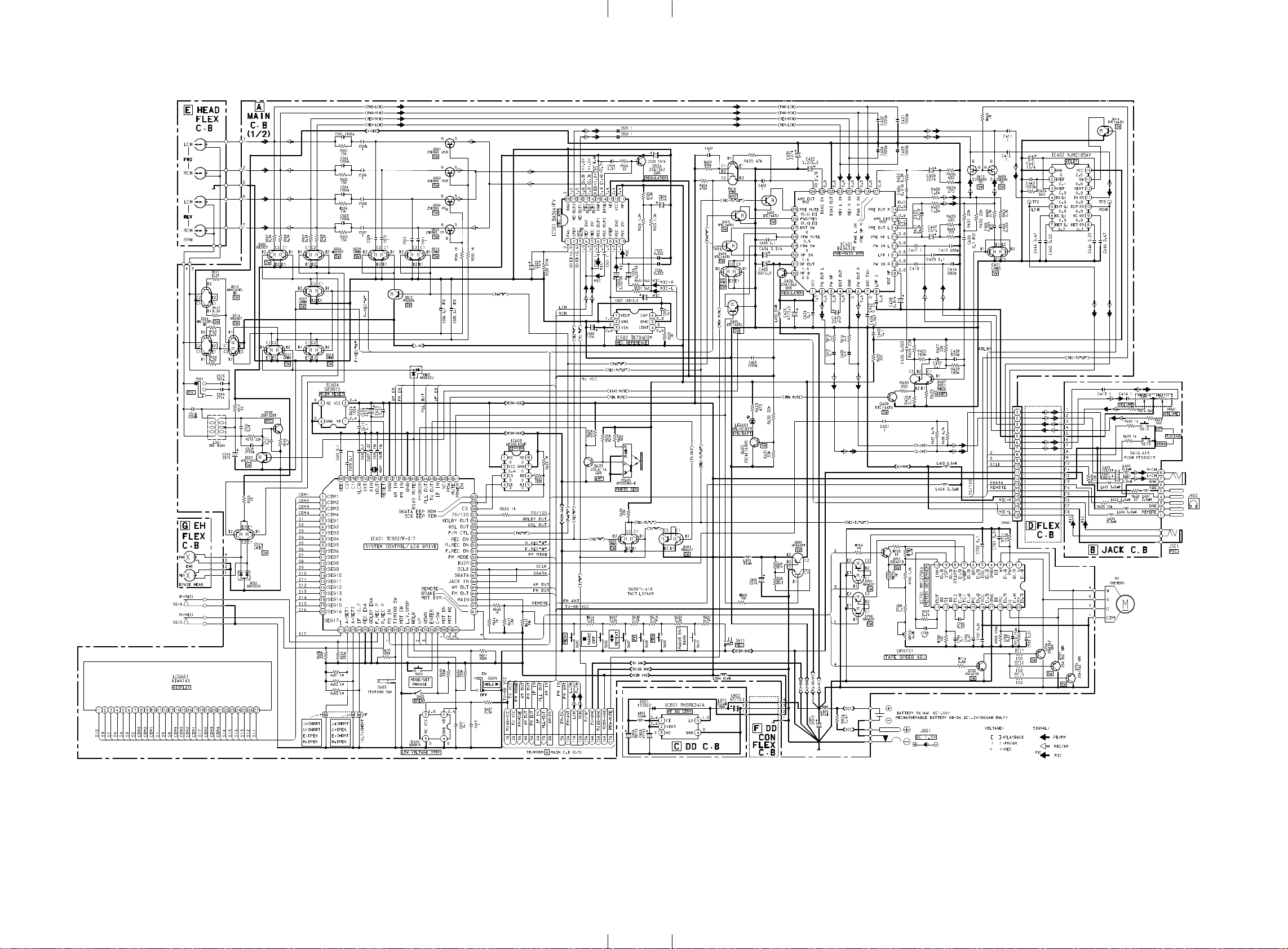
SCHEMATIC DIAGRAM – 2 (MAIN:1/2 / JACK / DD / FLEX) <HS-JX808 / 808D>
19 20

SCHEMATIC DIAGRAM – 3 (MAIN:2/2)
21 22

IC BLOCK DIAGRAM
IC, BA3641FV
IC, MM1279XV
IC, TK11823
IC, NJM2185V
IC, BA3632K
23 24

IC DESCRIPTION
IC, TC9327F-017
Pin No. Pin Name I/O Description Pin No. Pin Name I/O Description
1 ~ 4 COM1~COM4 O LCD common output 1~4.
5 ~ 21 SEG1 ~ SEG17 O LCD segment output 1~17.
Input pin for switching J , U , E , H areas.
J area U area E area H area
A-SET1 L L H H
22,23 A-SET1,2 I
A-SET2 L H L H
24 IF 10.7 I "H": IF 10.75 MHz. "L": 10.7 MHz.
25 REC ENA I Input pin for REC enable. "H": REC enable. "L": REC disable.
26 DOLBY ENA I Input pin for DOLBY enable. "H": DOLBY enable. "L": DOLBY disable.
27 F. REC P I "H": FWD REC shift disable. "L": enable.
28 R. REC P I "H": REV REC shift disable. "L": enable.
29 MS IN I Pin to input music sensor signal. "H": music exist. "L": blank.
30 TIMING SW I Pin to input for mechanism operation detection.
31 MOT CH I Pin to input for motor activation detection.
32 L.V. STOP I Stop mechanism operation and hold key input when low voltage is detected.
33 HOLD I "H": Hold OFF. "L": Hold ON.
34 UP I Up key input pin. "H": Key ON. "L": Key OFF.
35 DOWN I Down key input pin. "H": Key ON. "L": Key OFF.
36 ENTER I Enter key input pin. "H": Key ON. "L": Key OFF.
37 C-SW I Input pin for detecting the presence of cassette. "H": C-SW OFF. "L": C-SW ON.
38 MOT ON O Pin to output motor control. "H": Motor ON. "L": Motor OFF.
39 MOT HI O Pin to control motor. "H": Motor high speed. "L": Motor normal speed.
40 MOT DIR O Pin to output for motor rotation direction. "H": Clockwise. "L": Counter Clockwise.
41 BRAKE O Pin to output brake control for motor. "H": Brake ON. "L": Brake OFF.
56 DOLBY OUT O DOLBY ON/OFF control output pin.
57 70/120 O Pin to output normal tape and metal tape switching.
58 CS O Pin to control READ,WRITE of EEPROM.
59 SCK EEPROM O Pin to output serial clock of EEPROM.
60 SDATA EEPROM I/O Pin to input/output data of EEPROM.
61 POWER ON O "H": POWER ON. "L": POWER OFF.
62 POW MUTE O Pin to output muting. "H": MUTE ON. "L": MUTE OFF.
63 NC – Not connected.
64 IF IN I Pin to input IF signal.
65 TU OUT O Output "H". "H": TU mode. "L": except TU mode.
66 PLL OUT O Output phase comparison instrument.
67 P-SNSR I Pin to input photo sensor waveform output.
68 BIAS MUTE O Pin to output mute when REC. "H": MUTE ON. "L": MUTE OFF.
69 GND – GND.
70 FM IN I Input FM programmable counter.
71 AM IN I Input AM programmable counter.
72 VDD – Pin to apply voltage.
73 RESET I Pin to input system reset signal.
74 XOUT O Crystal oscillation pin.
75 XIN I Crystal oscillation pin.
76 VXT – Power supply pin for crystal oscillation.
77 VLCD – Reference voltage pin for LCD drive.
78 C1 – Reference voltage pin for LCD drive.
79 C2 – Reference voltage pin for LCD drive.
80 VEE – 1.5V constant voltage power supply pin for LCD drive.
42 REMOTE I Remote control key input pin.
43 MAIN I Main unit key input pin.
44 FM OUT O Pin to output for FM mode. "H": FM mode. "L" except FM mode.
45 AM OUT O Pin to output for AM mode. "H": AM(MW) mode. "L" except AM(MW) mode.
46 JACK IN I This is a pin where HP plug input is detected. "H": no plug. "L" plug exist.
47 SDATA O Pin to output data for remote controller display.
48 SCLK I Pin to input serial clock.
49 BUZR O Output buzzer.
50 FM MODE O Pin to output FM MONO/ST switching.
51 F. REC ON O "H": FWD REC mode. "L": Other mode.
52 R.REC ON O "H": REV REC mode. "L": Other mode.
53 REC ON O "H": REC mode. "L": Other mode.
54 F/R CTL O Output pin for tape run direction. "H": FWD direction. "L": REV direction.
55 DSL OUT O Pin to output DSL ON/OFF control.
25
26

ADJUSTMENT
MAIN C.B
A
PRACTICAL SERVICE FIGURE
<TUNER SECTION>
<TAPE SECTION>
5
L251
BAR ANT
VT GND
TP2 (LCH)
TP3 (RCH)
2
TC202
9
8
6
TC201
TP1(VT)
B
4
3
TC251
1
JACK C.B
J402
5
IFT251
PHONES
7
VR251
IC251
SFR701
8
DOLBY GND
12
11
<FM SECTION>
Sensitivity :
(IHF, THD 3%) Less than 17dB
[at 87.5 / 98.5 / 108.0MHz]
Distortion : Less than 3% (at input 54dB)
Less than 5% (at input 110dB)
[at 98.5MHz]
Stereo separation : More than 16dB
[at 98.5MHz]
Auto stop level : 20dB ± 6dB
[at 98.5MHz]
Intermediate frequency : 10.7 / 10.75MHz ± 0.05MHz
<AM SECTION>
Sensitivity :
(S/N 10dB) Less than 58dB
[at 630kHz]
Less than 56dB
[at 999 / 1440kHz]<AH>
[at 1000 / 1440kHz]<AU>
S/N ratio : More than 26dB
(Input 74dB) [at 630kHz]
More than 27dB
[at 999 / 1440kHz]<AH>
[at 1000 / 1440kHz]<AU>
Distortion : Less than 5% (at input 74dB)
Less than 10% (at input 120dB)
[at 999 / 1440kHz]<AH>
[at 1000 / 1440kHz]<AU>
Auto stop level : 60dB ± 7dB
[at 999 / 1440kHz]<AH>
[at 1000 / 1440kHz]<AU>
Intermediate frequency : 450kHz ± 3kHz
Tape speed : 3015Hz ± 50Hz
Wow & flutter : Less than 0.52% (RMS)
Take-up torque : 20 ~ 30g-cm (FWD, REV)
F.F torque : 70 ~ 150g-cm
Rew torque : 70 ~ 150g-cm
Back tension : 1.0 ~ 3.0g-cm (FWD, REV)
S/N ratio : More than 43dB (PB, DC)
More than 20dB (REC/PB, DC)
Distortion : Less than 3.0% (PB, DC)
Less than 7.0% (REC/PB, DC)
Noise level : Less than 3.0mV (PB, DC, MAX.)
Less than 0.3mV (PB, DC, MIN.)
Erasing Ratio: More than 45dB
Dolby level : 31.6mV ± 1dB
Dolby NR effect : More than 8.5dB (B-TYPE)
Frequency response : 63Hz +2/–6dB ~ 8kHz ± 4dB
(NORMAL, PB)
63Hz +2/–6dB ~ 10kHz ± 4dB
(CRO2, PB)
125Hz –4/–12dB ~ 8kHz +3/–12dB
(REC/PB)
Test tape : MTT–15070
TTA–100
TTA–200
TTA–210
TTA–320(NORMAL)
TTA–310(CRO2)
TTA–601
TTA–610
<TUNER SECTION>
1. AM IF Adjustment
IFT251 .................................................................. 450kHz
2. FM IF Adjustment
TC202................................................................ 10.7MHz
3. AM VT Check
Settings : • Test point : TP1 (VT)
Method : Set to AM 531kHz<AH>, 530kHz<AU>
and check that the test point voltage is
1.3V ± 0.3V. Then set to AM 1602kHz<AH>,
1710kHz<AU> and check that the test point
voltage is within 6.7 ~ 8.2V<AH>,
6.5 ~ 8.0V<AU>.
4. FM VT Check
Settings : • Test point : TP1 (VT)
Method : Set to FM 87.5MHz and check that the test
point voltage is 3.6V ± 0.4V. Then set to FM
108.0MHz<AH>, 108.1MHz<AU> and check
that the test point voltage is within 6.8 ~ 9.0V.
5. AM Tracking Adjustment
L251 .....................................................................630kHz
TC251.................................................................1440kHz
6. FM Tracking Adjustment
TC201 ............................................................... 87.5MHz
7. FM VCO Adjustment
Settings : • Adjustment location : VR251
Method : Connect a frequency counter to pin 11 and 12
of IC251, adjust VR251 for VCO to 19kHz ±
100Hz.
<TAPE PLAYER SECTION>
8. Tape Speed Adjustment
Settings : • Test tape : TTA–100
• Test point : PHONES JACK
(J402)
• Volume : MAX.
• Adjustment location : SFR701
Method : Play back the test tape and adjust SFR701 for
3015Hz ± 10Hz(FWD) and 3015Hz ± 45Hz
(REV).
9. Dolby Level Check
Settings : • Test tape : TTA-200
• Test point : TP2(Lch), TP3(Rch)
• Volume : MIN.
• DOLBY SW : OFF
Method : Connect an electrolytic capacitor (10uF/16V)
to measured instrument and test point, check
the voltage for 31.6mV ± 1dB.
27 28
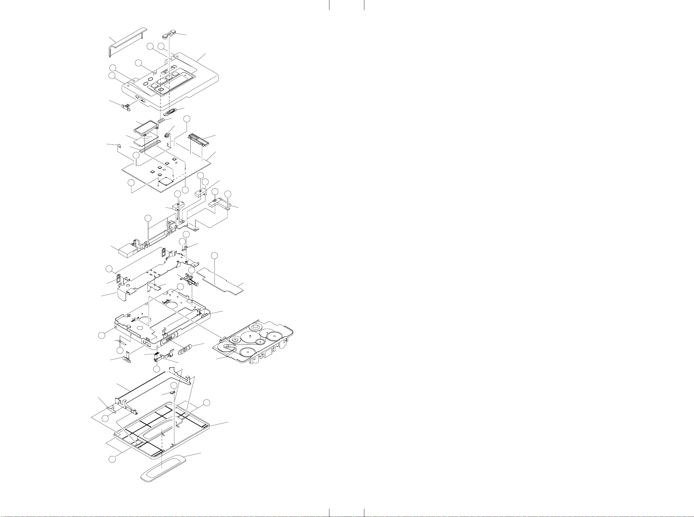
MECHANICAL EXPLODED VIEW 1/1 MECHANICAL PARTS LIST 1 /
C
DESCRIPTIONREF. NO. KANRI
C
B
8
9
E
B
JACK, 3.5 BLK
B
REF. NO. DESCRIPTIONPART NO. DESCRIPTIONREF. NO. KANRI
24
NO.
D
27
25
22
D
3
7
MAIN C.B
H
K
G
JACK, 3.5 ST 5P
I
<807AH, 807AU, 807DAH>
H
G
JACK, DIA 3.5
<808AH, 808DAH>
B
J
PLATE, GND
F
B
4
11
A
JACK C.B
6
PART NO. KANRI
NO.
1 88-HJ3-006-010 LID,BAT
2 88-HJ3-211-010 TERMINAL,BAT+
3 88-HJ3-212-010 TERMINAL,BAT4 88-HJ3-015-010 KEY,TUNING
5 88-HJ3-210-010 HLDR,BAT
6 88-HJ3-004-010 FRAME,CENTER<808AH,808DAH>
6 88-HJ3-020-010 FRAME,CENTER LOW<807AH,807AU,807DAH>
7 88-HJ3-204-010 HLDR,ANTENNA
8 88-HR4-201-010 HLDR,LCD
9 88-HR4-202-010 CONN,RUBBER LCD
10 88-HJ3-206-010 PLATE,HINGE
11 88-HJ3-205-010 SPR-P,CASS
12 88-HJ3-202-010 HLDR,CASS
13 88-HJ3-203-010 SPR-P,CLICK
14 88-HJ3-201-010 STOPPER,CASS
15 88-HJ3-002-010 LID,CASS S<808AH,808DAH>
15 88-HJ3-021-010 LID,CASS S JX807<807AH,807AU,807DAH>
16 88-HJ3-007-010 WINDOW,CASS
17 88-HJ3-010-010 KNOB,SL SIDE
18 88-HJ3-208-010 NUT,FRONT
19 88-HJ3-009-010 KNOB,SL HOLD
20 88-HJ3-008-010 KNOB,SL OPEN
21 87-HR5-225-010 SPR-E,EJECT N
22 82-HK3-206-110 C-SP,LOCK
23 88-HJ3-207-010 PLATE,LOCK
24 88-HJ3-011-010 KNOB,SL REC
25 87-HR6-219-010 SPR-P,POP UP
26 87-HR6-219-010 SPR-P,POP UP
27 09-028-360-010 CABI,REAR ASSY<808AH,808DAH>
27 09-028-359-010 CABI,REAR ASSY<807AH,807AU,807DAH>
A 88-HJ3-220-010 S-SCREW,+1.4-0.7-1 CR NL
B 87-067-384-010 SCREWVT1.4-3.5HL
C 86-HK4-224-010 S-SCREW,SERR+1.4-3.5 CR L
D 87-078-153-010 SCRW,1.4-2.5 CR
E 87-067-534-010 SCREW,VT-1.4-6
F 87-078-113-010 S-SCRW,+1.4-3.5 HL(B
G 87-078-185-010 SCRW-SR,1.4-4.5 BL
H 87-262-512-310 V+1.4-5.5
I 87-078-218-010 SCRW-SERR,M1.4-5.3<807AH,807AU,807DAH>
J 88-HK5-228-010 S-SCREW,+1.4-2 CR
K 88-HR4-222-010 S-SCREW,+1.4-1.6 CR (0.2)
L 86-HJ3-222-010 S-SCREW,SERR+1.4-2 CR L
M 87-078-216-010 SCRW-SR,1.4-1.4B LS
N 88-HJ3-219-010 S-SCREW,+1.4-2.5 B HL(0.3)
O 87-HK5-235-010 S-SCREW,1.4-0.6-2.5
PART NO. KANRI
NO.
1
D
17
LCD601
2
5
D
SW, LEAF REC
10
REF. NO. DESCRIPTIONPART NO.
NO.
13
18
A
19
26
B
21
23
20
6ZM-2 R2
L
12
L
14
L
M
15
16
L
29 30

SPRING APPLICATION POSITION
86-ZM2-245-310
SPR-C,SLIP L
86-ZM2-243-310
SPR-C,BT
C0.3
86-ZM2-213-210
SPR-C,FR
86-ZM2-243-310
SPR-C,BT
86-ZM2-241-210
SPR-C,SLIP R
86-ZM2-217-210
SPR-E,CAM L
86-ZM2-230-110
SPR-T,PINCH L
86-ZM2-255-010
SPR-T,PIN BACK L
86-ZM2-220-210
SPR-T,HEAD
86-ZM2-254-010
SPR-T,PIN BACK
86-ZM2-215-210
SPR-E,CAM R
86-ZM2-229-110
SPR-T,PINCH R
31

TAPE MECHANISM EXPLODED VIEW 1/1
A
EH FLEX C.B
HEAD FLEX C.B
A
6
42
5
SH,1.2-2.9-0.25SL
e
20
21
22
25
17
SHAFT CAPSTAN
26
45
10
7
9
b
c
G
f
F
a
SH,1.2-2.9-0.25SL
43
c
b
a
24
D
35
34
11
15
16
23
14
H
B
PLATE,THRUST
2
41
1
8
13
30
27
31
f
38
4
6
43
G
28
29
D
F
37
3
d
e
d
32
E
40
19
12
22
46
36
47
33
18
C
F
SHAFT
CAPSTAN
44
17
H
39
32

TAPE MECHANISM PARTS LIST 1/1
PART NO. KANRI
NO.
1 86-ZM2-255-010 SPR-T,PIN BACK L
2 86-ZM2-286-210 GUIDE,TAPE REC
3 86-ZM2-220-210 SPR-T,HEAD
4 86-ZM2-285-110 LEVER,HEAD REC
5 86-ZM2-247-210 LEVER,MS
6 86-ZM2-226-110 ROLLER ASSY,PINCH
7 86-ZM2-254-010 SPR-T,PIN BACK
8 86-ZM2-230-110 SPR-T,PINCH L
9 86-ZM2-229-110 SPR-T,PINCH R
10 86-ZM2-240-110 CAP,REEL
11 86-ZM2-234-110 SHAFT,REEL R
12 86-ZM2-251-210 SHAFT,GEAR B
13 86-ZM2-308-310 CHAS ASSY,OUT-SERT R
14 86-ZS2-312-010 SPR-P,6A-MOT
15 86-ZM2-232-210 LEVER,REEL R
16 86-ZM2-258-610 GEAR,REW
17 86-ZM2-243-310 SPR-C,BT
18 86-ZM2-329-110 BELT,P5
19 86-ZM2-209-110 GEAR,B
20 86-ZM2-238-610 GEAR,FF
21 86-ZM2-245-310 SPR-C,SLIP L
22 86-ZM2-237-010 GEAR,PLAY
23 86-ZM2-241-210 SPR-C,SLIP R
24 86-ZM2-272-010 LEVER,SW P 8.4
25 86-ZM2-236-210 CAP,SLIP
26 86-ZM2-235-210 SHAFT,REEL L
27 86-ZM2-223-210 LEVER,PIN UP L
28 86-ZM2-233-310 LEVER,REEL L
29 86-ZM2-208-210 GEAR,A
30 86-ZM2-217-210 SPR-E,CAM L
DESCRIPTIONREF. NO. KANRI
REF. NO. DESCRIPTIONPART NO.
NO.
31 86-ZM2-216-410 LEVER,CAM L
32 86-ZM2-276-010 PULLEY,COUPLER
33 86-ZM2-212-210 SHAFT,FR
34 86-ZM2-214-410 LEVER,CAM R
35 86-ZM2-215-210 SPR-E,CAM R
36 86-ZM2-222-210 LEVER,PIN UP R
37 86-ZM2-218-110 LEVER,HEAD UP
38 86-ZM2-205-410 FLY-WHL,L
39 86-ZM2-330-010 FLY-WHL,R2
40 86-ZM2-282-010 SH,AUTO 2
41 86-ZM2-225-310 ARM,PINCH L
42 86-ZM2-224-210 ARM,PINCH R
43 86-ZM2-283-010 CAP,SHAFT
44 86-ZM2-275-110 CAP,SLIP R
45 86-ZM2-210-610 LEVER,FR
46 86-ZM2-211-210 GEAR,FR
47 86-ZM2-213-210 SPR-C,FR
A 86-ZM2-296-110 S-SCREW,+1.4-8.45
B 87-067-430-010 VT1.4-5 BLK
C 87-067-516-010 PW,3-1.58-0.25,SLIT
D 87-067-860-010 PW,3-0.95-0.4
E 86-ZM2-277-010 W-P,0.8-3-0.2 SLT
F 86-ZM2-319-010 W-L,0.95-3-0.35
G 86-ZM2-313-010 W-P,1.76-4-0.13
H 86-ZM2-278-010 W-P,1.36-4-0.2 SLT
33

A4
L
9420025 931261
211, IKENOHATA 1CHOME, TAITO-KU, TOKYO 110, JAPAN TEL:03 (3827)
3111
Printed in Singapore
 Loading...