

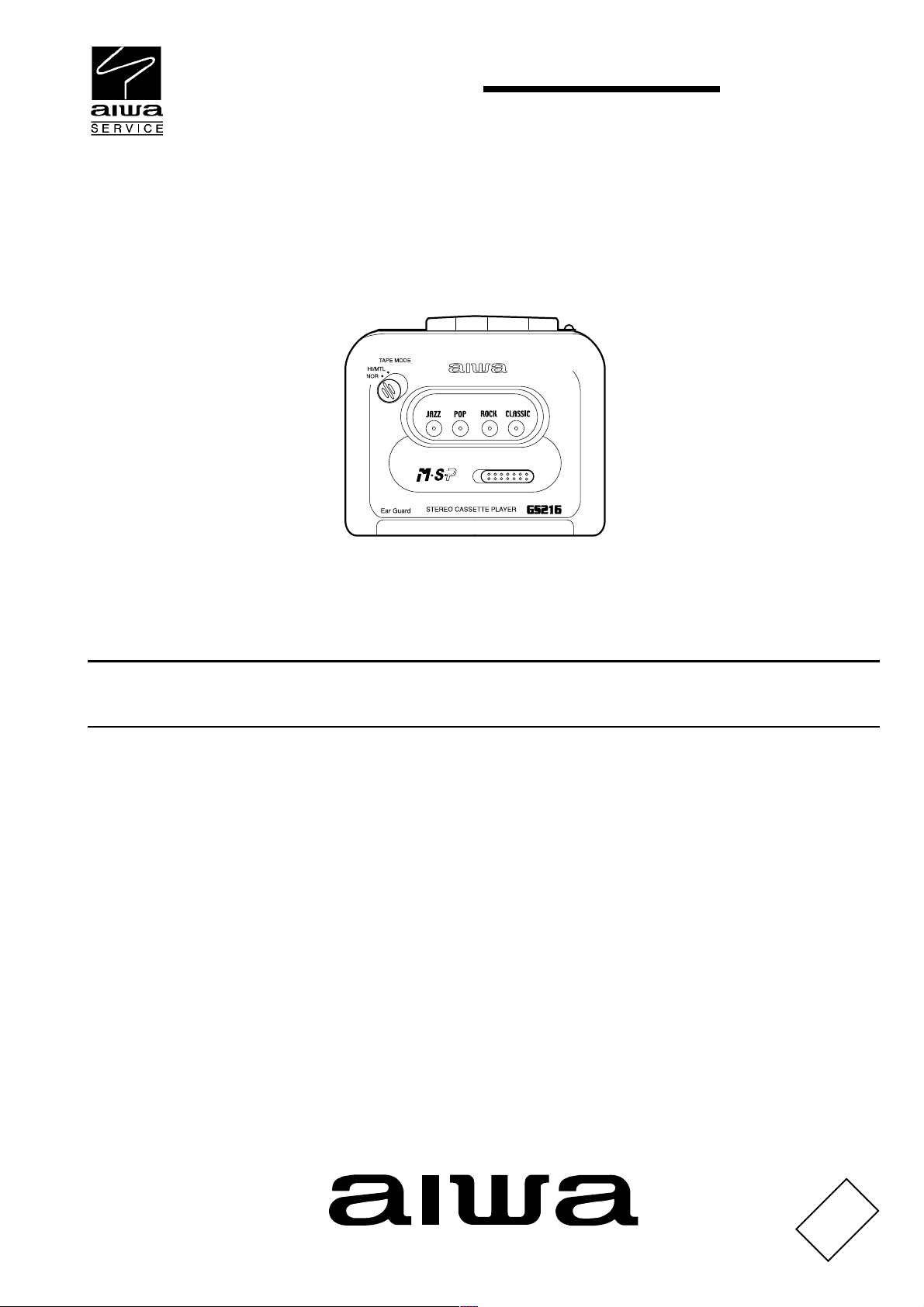
HS-GS216
Y,YH
SERVICE MANUAL
STEREO
CASSETTE PLAYER
BASIC TAPE MECHANISM : 8ZM-3 P2N
S/M Code No. 09-012-439-0N1
DATA

SPECIFICATIONS
Maximum output: 4 mW + 4 mW (EIAJ 16 ohms)<Y>
Load impedance<Y>: 16 - 80 ohms
Power source: DC 3V using two R6 (size AA) batteries
Maximum outside dimensions:
Weight Approx. 130g (4.6 oz) excluding batteries
Design and specifications are subject to change without notice.
5 mW + 5 mW (EIAJ 32 ohms)<YH>
AC house current using an optional AC adaptor Aiwa AC-D302
111.3 (W) x 83 (H) x 29.4 (D) mm
(4 1/2 x 3 3/8 x 1 3/
(excluding projecting parts and controls)
in.)
16
ACCESSORIES / PACKAGE LIST
PART NO.
NO.
1 8B-HG9-902 -010 IB,(ECC)F GS216<YH>
1 8B-HG9-906-010 IB,(EDPHNC)F GS216<Y>
1 8B-HG9-905-010 IB,(EGFSI)F GS216<Y>
2 87-B30-255-010 HEADPHONE,HP-M007B(S)
3 8Z-HRB-050-210 CLIP,BELT ASSY
DESCRIPTIONREF. NO. KANRI
2
ELECTRICAL MAIN PARTS LIST 1 / 1
REF. NO.
IC
87-A20-461-040 C-IC,MM1336DF
TRANSISTOR
87-026-264-080 C-TR,RN1411
89-327-125-080 CHIP TR,2SC2712GR
DIODE
87-A40-630-040 C-DIODE,RB411D
87-020-027-080 CHIP-DIODE 1SS184
MAIN C.B
C101 87-010-178-080 CHIP CAP 1000P-50
C102 87-010-178-080 CHIP CAP 1000P-50
C103 87-010-213-080 C-CAP,S 0.015-50 B
C104 87-010-213-080 C-CAP,S 0.015-50 B
C105 87-010-499-040 CAP,E 22-6.3 GAS
C106 87-010-499-040 CAP,E 22-6.3 GAS
C111 87-010-182-080 C-CAP,S 2200P-50 B
C112 87-010-182-080 C-CAP,S 2200P-50 B
C119 87-010-503-040 CAP,E 220-4 GAS
C120 87-016-350-040 CAP,E 470-4 MA GAS
C121 87-010-805-080 CAP, S 1-16
C122 87-010-178-080 CHIP CAP 1000P-50KB
C123 87-010-494-040 CAP,E 1-50 GAS
C124 87-010-596-080 CAP, S 0.047-16
C125 87-010-499-040 CAP,E 22-6.3 GAS
C126 87-010-503-040 CAP,E 220-4 GAS
C127 87-010-197-080 CAP, CHIP 0.01 DM
C128 87-010-196-080 CHIP CAPACITOR,0.1-25
C230 87-010-196-080 CHIP CAPACITOR,0.1-25
C301 87-010-196-080 CHIP CAPACITOR,0.1-25
C302 87-010-196-080 CHIP CAPACITOR,0.1-25
C303 87-016-087-080 C-CAP,S 0.47-16F
C304 87-016-087-080 C-CAP,S 0.47-16F
C305 87-010-186-080 CAP,CHIP 4700P
C306 87-010-186-080 CAP,CHIP 4700P
C307 87-010-186-080 CAP,CHIP 4700P
C308 87-010-186-080 CAP,CHIP 4700P
C309 87-010-193-080 CHIP CAPACITOR,0.033
C310 87-010-193-080 CHIP CAPACITOR,0.033
C311 87-010-805-080 CAP, S 1-16
PART NO. DESCRIPTIONREF. NO.
KANRI
NO.
DESCRIPTION
PART NO.
C312 87-010-805-080 CAP, S 1-16
C313 87-010-805-080 CAP, S 1-16
C321 87-A10-952-080 C-CAP,TN 22-4 M A MCM
C322 87-010-596-080 CHIP CAPACITOR,0.047-16KR
C403 87-010-197-080 CAP, CHIP 0.01 DM
C404 87-010-197-080 CAP, CHIP 0.01 DM
C405 87-012-141-080 CHIP-CAPACITOR,0.22-16F
C406 87-012-141-080 CHIP-CAPACITOR,0.22-16F
C407 87-010-805-080 CAP, S 1-16
C408 87-010-805-080 CAP, S 1-16
C409 87-010-195-080 C-CAP,S 0.068-25 F
C410 87-010-195-080 C-CAP,S 0.068-25 F
C411 87-010-188-080 CAP,CHIP 6800P
C412 87-010-188-080 CAP,CHIP 6800P
C413 87-010-198-080 CAP, CHIP 0.022
C414 87-010-198-080 CAP, CHIP 0.022
C415 87-010-501-040 E/CAP GAS 47-4
C417 87-010-198-080 CAP, CHIP 0.022
C418 87-010-198-080 CAP, CHIP 0.022
C420 87-010-805-080 CAP, S 1-16
C421 87-010-805-080 CAP, S 1-16
C701 87-012-157-080 C-CAP,S 330P-50 CH
C702 87-012-157-080 C-CAP,S 330P-50 CH
C703 87-010-196-080 CHIP CAPACITOR,0.1-25
C704 87-010-197-080 CAP, CHIP 0.01 DM
C705 87-010-197-080 CAP, CHIP 0.01 DM
C706 87-012-141-080 CHIP-CAPACITOR,0.22-16F
J101 87-A61-124-110 JACK,DC DIA2.75 BLK TC
J102 85-HRL-623-010 JACK,3.5 ST BLK
S101 87-A91-077-010 SW,LEAF
S102 8Z-HRB-607-010 SW,SL 2-2-2 SSZZ-S-502(S)
S301 87-A90-917-010 C-SW,SL 1-1-2 SS-350-B12W-C-L
S401 87-A91-285-110 C-SW,SL 1-1-4 SS-350-B14B-C-L
SFR101 87-024-050-010 SFR,1K V VZ066H1
TH101 87-026-256-090 THERMISTOR, HT-100
VR101 87-A90-818-010 VR,RTRY 20KCX2H XV0102G
KANRI
NO.
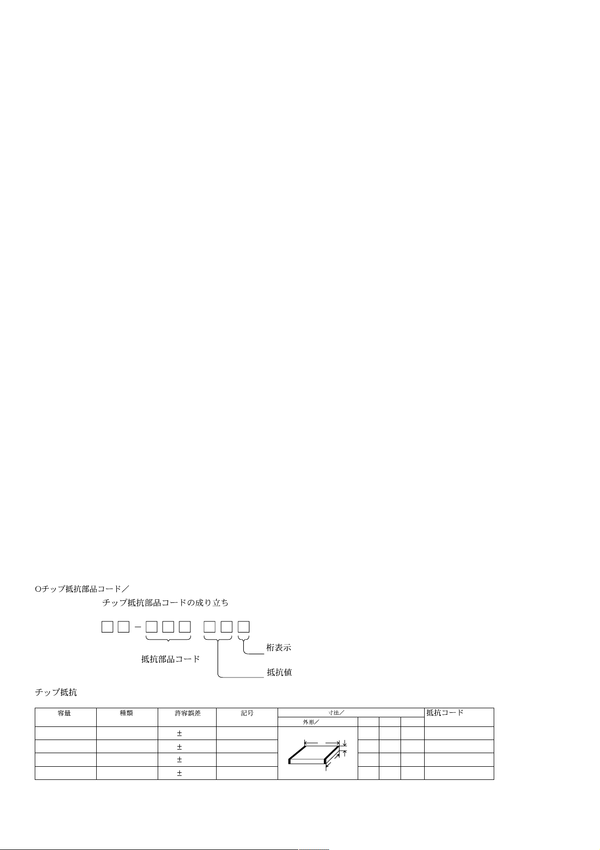
CHIP RESISTOR PART CODE
Chip Resistor Part Coding
88
A
Resistor Code
Chip resistor
Wattage Type Tolerance
1/16W 1005 5% CJ
1/16W
1/10W
1/8W
1608
2125
3216
5%
5%
5%
Symbol
CJ
CJ
CJ
Figure
Value of resistor
Form
L
3
Dimensions (mm)
t
W
0.55
Resistor Code
108
118
128
LW t
1.0 0.5 0.35 104
1.6 0.8 0.45
2 1.25 0.45
3.2
1.6
: A
: A

TRANSISTOR ILLUSTRATION
C
B
E
2SC2712
RN1411
4

WIRING
32 31 30 29 28 27 26 25 24 23 22 21 20 19 18 17 16 15 14 13 12 11 10 9 8 7 6 5 4 3 2 1
A
B
C
D
E
F
G
H
I
J
K
L
M
N
O
P
Q
5
R
S
T
U

SCHEMATIC DIAGRAM
REV
6

ADJUSTMENT
1. Tape Speed Adjustment
Settings : Test tape : TTA 100
(Tape center)
Test point : Phones Jack (J102)
Adjustment location : SFR101
Tape selector : NORM
Volume : Non clip
(MAX 10 dB down)
Method : Play back the test tape and adjust SFR101 so that the
frequency becomes 3000 Hz ± 10 Hz. Then confirm
WOW is less than 0.50%.
2. GOVERNER Check
Perform the STOP > PLAY and REVERSE operations
(or PAUSE ON > OFF) after the motor is replaced. When the tape
starts running smooth, this adjustment is not necessary. If wow is
conspicuous at the beginning of the tape-run, perform this adjustment
following the procedures below.
1) Solder resistor pattern (C) of the MOTOR AND
GOVERNOR MATCHING ADJ. resistor group.
2) Set the tape speed (using speed adjustment SFR101).
3) Restrict the motor rotation by hand (or turn PAUSE ON).
4) Remove your hand and listen to the beginning of the
tape-run.
5) When the rise of tape running is smooth, no more
adjustment is necessary.
If wow continues for 1 to 2 seconds at the rise time, change
the combined resistance according to procedure 2 and check
that the tape starts running smooth.
6) Solder the resistor pattern according to the table below
Pattern
Step (1)
Step (2)
Step (3)
(NOTE : = 2.7 ohm, = 4.7 ohm, = 10 ohm)
7) Finally re-check the tape speed.
Low
resistance
Open
Open
Open
A
A
Medium
resistance
Open Open
Solder
B
B
High
resistance
SolderOpen
Open
C
C
Caution : Cool the patterns down to normal temperature
after soldering. If the pattern remains heated,
the gorvernor circuit does not operate normally.
7

MECHANICAL EXPLODED VIEW 1 / 1
8ZM-3 P2N
6
2
1
3
B
5
4
PWB
C
14
B
B
D
7
10
8
12
11
9
13
8

MECHANICAL PARTS LIST 1 / 1
REF. NO.
1 8B-HG6-007-010 LID,CASS P EG<Y>
1 8B-HG9-004-010 LID,CASS<YH>
2 8Z-HRB-217-110 SPR-T,CASS
3 8Z-HRB-002-010 WINDOW,CASS
4 8Z-HRB-208-010 BAT-CONTACT,P
5 8B-HRC-203-010 BAT-CONTACT,M
6 8Z-HG9-201-110 HLDR,HP JACK
7 8B-HG9-001-010 CABI,REAR EG<Y>
7 8B-HG9-003-010 CABI,REAR<YH>
8 8B-HG6-201-010 RACK,MSP
9 8B-HG6-202-010 GEAR,MSP
10 8B-HG6-005-010 PLATE,IND MSP
11 8B-HG6-004-010 KNOB,SL DOLBY
12 8B-HG6-003-010 KNOB,SL MSP
13 8B-HG6-002-010 PANEL,MSP
14 8Z-HRB-005-110 LID,BAT SIL
A 87-B10-048-010 VT2+1.4-3 (3) CR HL
B 87-B10-196-010 VT2+1.4-4 BLK (3) HL
C 87-264-527-310 V 1.7-3 SCREW
D 87-067-384-010 SCREWVT1.4-3.5HL
PART NO. DESCRIPTIONREF. NO.
KANRI
NO.
DESCRIPTION
PART NO.
KANRI
NO.
COLOR NAME TABLE
Basic color symbol Color Basic color symbol Color Basic color symbol Color
B Black C Cream D Orange
G Green H Gray L Blue
LT Transparent Blue N Gold P Pink
R Red S Silver ST Titan Silver
T Brown V Violet W White
WT Transparent White Y Yellow YT Transparent Yellow
LM Metallic Blue LL Light Blue GT Transparent Green
LD Dark Blue DT Transparent Orange GM Metallic Green
YM Metallic Yellow DM Metallic Orange PT Transparent Pink
LA Aqua Blue GL Light Green HT Transparent Gray
9

TAPE MECHANISM EXPLODED VIEW 1 / 1
32
38
W-P1.16-2.8-0.4
25
23
26
30
24
21
27
28
29
31
19
20
33
29
22
17
36
34
18
16
35
41
37
40
44
47
46
43
48
49
42
39
50
51
52
11
45
12
10
A
9
7
6
A
7
8
A
13
15
14
1
5
3
53
54
55
56
57
2
10
4

TAPE MECHANISM PARTS LIST 1 / 1
REF. NO.
1 8Z-HRB-003-210 FRAME,CENTER GRY
2 8Z-HRB-207-110 SPR-P,CASS
3 88-ZM3-253-210 SPR-C,BT L
4 88-ZM3-274-010 GEAR,REEL A
5 8Z-HRB-014-110 KNOB,SL OPEN
6 8Z-HRB-204-110 LEVER,EJECT
7 8Z-HRB-216-110 CAP, EJECT
8 8Z-HRB-205-110 SPR-T,EJECT
9 8Z-HRB-215-010 SHAFT,ASSY
10 87-A91-379-010 MOT,BCY3B-13
11 88-ZM3-236-010 PULLEY,MOT S
12 88-ZM3-263-210 BELT,S
13 88-ZM3-243-010 SPR-T,PLAY BACK
14 8Z-HRB-206-010 PLATE,EJECT
15 88-ZM3-217-210 ARM,PINCH L
16 88-ZM3-241-110 SPR-T,PINCH L
17 88-ZM3-003-110 LEVER,REW
18 88-ZM3-246-110 SPR-T,FF REW
19 87-A80-115-010 F-CABLE,5P P2
20 87-A91-019-010 HEAD ASSY,PH 8ZM-3
21 88-ZM3-211-010 LEVER,DIR
22 88-ZM3-001-110 LEVER,PLAY
23 88-ZM3-213-310 LEVER,T-UP
24 88-ZM3-225-110 GEAR,PLAY
25 88-ZM3-224-210 GEAR,TRANSMIT
26 88-ZM3-002-110 LEVER,FF
27 88-ZM3-242-210 SPR-T,PINCH R
28 88-ZM3-242-210 ARM,PINCH R
29 88-ZM3-271-010 ROLLER ASSY,PINCH
30 88-ZM3-220-110 BTN,MODE SEL
31 88-ZM3-267-010 SHAFT,PULLEY TWIN
32 88-ZM3-234-010 PULLEY,BELT TWIN
33 88-ZM3-212-110 LEVER,LOCK
34 88-ZM3-245-110 SPR-T,LOCK
35 88-ZM3-201-410 CHAS ASSY,OUTSERT P
36 88-ZM3-216-110 LEVER,SW
37 88-ZM3-221-110 GEAR,AUTO
38 09-001-453-010 FLY-WHL ASSY,R S
39 88-ZM3-280-010 FLY-WHL ASSY,L2
40 88-ZM3-248-010 SPR-T,AUTO CHOOSE
41 88-ZM3-215-110 LEVER,AUTO KICK
42 88-ZM3-262-010 BELT,L
43 88-ZM3-244-010 SPR-T,DIR
44 88-ZM3-219-010 BTN,DIR KNOB
45 8A-HRH-203-010 HLDR,DC JACK
46 88-ZM3-226-010 GEAR,IDLE
47 88-ZM3-004-210 LEVER,STOP
48 88-ZM3-255-210 SPR-C,STOP
49 88-ZM3-214-110 LEVER,AUTO FIND
50 88-ZM3-238-010 CAP,SLIP
51 88-ZM3-252-010 SPR-C,SHIFT
52 88-ZM3-251-310 SPR-C,SLIP
53 88-ZM3-222-110 GEAR,SLIP FAST
54 88-ZM3-269-110 FELT,SLIP
55 88-ZM3-237-110 CLR,SLIP
56 88-ZM3-247-010 SPR-T,AUTO FIND
57 88-ZM3-223-010 GEAR,SLIP SLOW
58 8A-HRH-203-010 HLDR,DC JACK
A 87-067-384-010 SCREWVT1.4-3.5HL
PART NO. DESCRIPTIONREF. NO.
KANRI
NO.
DESCRIPTION
PART NO.
KANRI
NO.
11

211, IKENOHATA 1CHOME, TAITO-KU, TOKYO 110, JAPAN TEL:03 (3827) 3111
Printed in Singapore9630472 0251431
 Loading...