

Page 1
HS-PS301
Y,YH
HS-EM40MK3
Y
SERVICE MANUAL
STEREO CASSETTE PLAYER BASIC TAPE MECHANISM : 4ZM-2 P3NC2
• This Service Manual is the "Revision Publishing" and replaces "Simple Manual"
(S/M Code No. 09-001-427-3T1).
S/M Code No. 09-003-427-3R1
REVISION
DATA
Page 2

SPECIFICATIONS
Maximum output: 4 mW + 4 mW (EIAJ 16 ohm) <Y>
Power source: DC 3 V using two R6 (size AA) batteries
Maximum dimensions: 116.4 (W) x 92 (H) x 34.9 (D) mm
Weight: Approx.114.2 g (4 oz) (excluding batteries)
• Design and specifications are subject to change without
notice.
• Dolby noise reduction manufactured under license from Dolby
Laboratories Licensing Corporation.
“DOLBY” and the double-D symbol are trademarks of Dolby
Laboratories Licensing Corporation.
15 mW + 15 mW (EIAJ 32 ohm) <YH>
AC house current using the optional AC adaptor
Aiwa AC-D302
(45/8 x 35/8 x 13/8 in.)
ACCESSORIES / PACKAGE LIST
PART NO.
NO.
1 8A-HK9-903-010 IB,Y(EGFSI)C-PS301<301Y>
1 8A-HK9-904-010 IB,Y(EDPOHCZ)C-PS301<301Y>
1 8A-HK9-905-010 IB,YH(ECC)-C<301YH>
1 8A-HK9-906-010 IB,Y(EGFSI)C-EM40MK3<40Y>
1 8A-HK9-907-010 IB,Y(EDPOHCZ)C-EM40MK3<40Y>
2 84-447-019-310 CLIP,BELT
3 87-B30-168-210 HEADPHONE,HP-M006(K)<301YH,301Y,[S]40Y>
3 87-B30-155-210 HEADPHONE,HP-M006 BL(T)<[LM]40Y>
3 87-B30-156-210 HEADPHONE,HP-M006 G(T)<[GM]40Y>
DESCRIPTIONREF. NO. KANRI
- 2 -
Page 3
ELECTRICAL MAIN PARTS LIST
TRANSISTOR ILLUSTRATION
PART NO. KANRI
NO.
IC
87-A21-638-040 IC,MM1336CF
87-017-805-080 IC,AN7375NS(OP AMP)
TRANSISTOR
87-026-264-080 C-TR,RN1411
DIODE
87-020-027-080 C-DIODE, 1SS184
87 -A40-630-040 C-DIODE, RB411D<YH>
MAIN C.B
C1 87-010-181-080 CAP,CHIP S 1800P
C2 87-010-181-080 CAP,CHIP S 1800P
C3 87-010-178-080 CHIP CAP 1000P
C4 87-010-178-080 CHIP CAP 1000P
C5 87-015-676-040 E/CAP 47/6.3
C6 87-015-676-040 E/CAP 47/6.3
C7 87-015-676-040 E/CAP 47/6.3
C8 87-010-196-080 CHIP CAPACITOR,0.1-25
C9 87-010-213-080 C-CAP,S 0.015-50 B
C10 87-010-213-080 C-CAP,S 0.015-50 B
C11 87-016-462-080 C-CAP,S 1-16 F
C12 87-010-194-080 CAP, CHIP 0.047
C13 87-015-681-040 E/CAP 10-16
C14 87-010-196-080 CHIP CAPACITOR,0.1-25
C15 87-016-462-080 C-CAP,S 1-16 F
C16 87-016-462-080 C-CAP,S 1-16 F
C17 87-010-180-080 C-CER 1500P
C18 87-010-180-080 C-CER 1500P
C20 87-A10-489-040 CAP,E 220-4 7L SR
C21 87-A10-489-040 CAP,E 220-4 7L SR
C22 87-016-462-080 C-CAP,S 1-16 F
C23 87-010-197-080 CAP, CHIP 0.01 DM
C24 87-010-197-080 CAP, CHIP 0.01 DM
C25 87-016-462-080 C-CAP,S 1-16 F
C26 87-016-462-080 C-CAP,S 1-16 F
DESCRIPTIONREF. NO. KANRI
REF. NO. DESCRIPTIONPART NO. DESCRIPTIONREF. NO. KANRI
NO.
C51 87-010-178-080 CHIP CAP 1000P
C52 87-010-196-080 CHIP CAPACITOR,0.1-25
C53 87-016-462-080 C-CAP,S 1-16 F
C54 87-A10-489-040 CAP,E 220-4 7L SR
C351 87-016-461-080 C-CAP,S 0.47-16F
C352 87-016-461-080 C-CAP,S 0.47-16F
C353 87-010-196-080 CHIP CAPACITOR,0.1-25
C354 87-010-196-080 CHIP CAPACITOR,0.1-25
C355 87-010-186-080 CAP,CHIP 4700P
C356 87-010-186-080 CAP,CHIP 4700P
C357 87-010-193-080 CHIP CAPACITOR,0.033
C358 87-010-193-080 CHIP CAPACITOR,0.033
C359 87-010-186-080 CAP,CHIP 4700P
C360 87-010-186-080 CAP,CHIP 4700P
C361 87-016-462-080 C-CAP,S 1-16 F
C362 87-016-462-080 C-CAP,S 1-16 F
C363 87-016-462-080 C-CAP,S 1-16 F
C364 87-016-462-080 C-CAP,S 1-16 F
C365 87-015-676-040 E/CAP 47/6.3
C367 87-010-188-080 CAP,CHIP 6800P
C368 87-010-188-080 CAP,CHIP 6800P
J1 85-HRL-623-010 JACK,3.5 ST BLK
J2 87-A61-124-010 JACK,DC DIA2.75 BLK TC<YH>
R54 87-022-657-080 RES,K34G 0.68
SFR1 87-A90-789-080 C-SFR,470 RH03AXA12X
SFR2 87-A90-789-080 C-SFR,470 RH03AXA12X
SFR51 87-024-197-010 SEMI-FIXED RESISTOR, 1K
SW1 87-A90-133-110 SW,LEAF LSA1120JAU
SW2 87-A91-163-010 C-SW,SL 1-1-2 4MM
TH51 87-026-256-090 THERMISTOR, HT-100
VR1 87-A91-724-010 VR,RTRY 20KAX2
FRONT C.B
C401 87-012-141-080 C-CAP,S 0.22-16 Z F C2012
C402 87-012-141-080 C-CAP,S 0.22-16 Z F C2012
SW351 87-036-304-080 C-SW,SL 1-1-2 SS-350
SW401 87-A90-330-080 C-SW,SL 1-1-2 SSSS81 T1.4
PART NO. KANRI
NO.
B
E
RN1411
REF. NO. DESCRIPTIONPART NO.
NO.
C
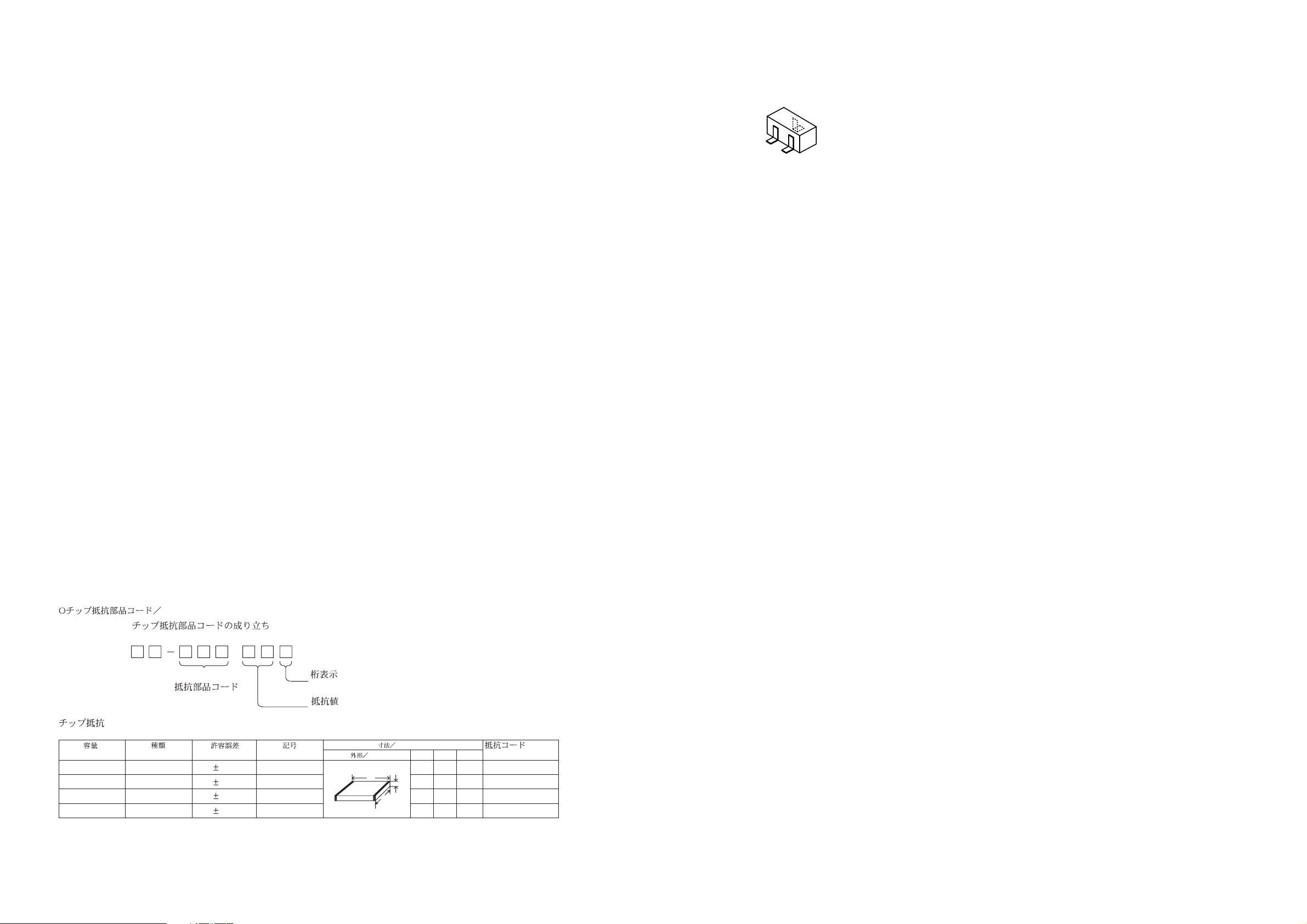
CHIP RESISTOR PART CODE
Chip Resistor Part Coding
88
A
Resistor Code
Chip resistor
Wattage Type Tolerance
1/16W 1005 5% CJ
1/16W
1/10W
1/8W
1608
2125
3216
5%
5%
5%
Symbol
CJ
CJ
CJ
Figure
Value of resistor
Form
L
Dimensions (mm)
t
W
0.55
Resistor Code
108
118
128
LW t
1.0 0.5 0.35 104
1.6 0.8 0.45
2 1.25 0.45
3.2
1.6
: A
: A
- 3 -
Page 4

WIRING
101112131415161718192021222324
1234567892526272829303132
A
B
C
D
E
F
G
H
I
J
K
L
M
N
O
P
Q
- 4 -
R
S
T
U
Page 5

SCHEMATIC DIAGRAM
- 5 -
Page 6

ADJUSTMENT
MECHANICAL EXPLODED VIEW 1 / 1
A
MAIN C.B
P HEAD
FWD
3
TP1
(L-CH)
A
*
B
C
SFR 51
Note :
* : On the other soldering pattern side.
4 2
1
*
TP2
(R-CH)
2
SFR 2
*
*
SFR 1
2
VOLUME
PHONES
VR1
J1
1
1. Tape Speed Adjustment
Settings : • Test tape : TTA – 100
(Tape center)
• Test point : Phones Jack (J1)
• Adjustment location : SFR51
• Tape selector : NORM
• Volume : Non – clip
(MAX – 10 dB down)
Method : Play back the test tape and adjust SFR51 so that the
frequency becomes 3000 Hz ± 10 Hz. Then confirm
WOW is less than 0.52%.
2. Dolby Level Adjustment
Settings : • Test tape : TTA – 200
• Test point : TP1 (L – CH)
TP2 (R – CH)
• Adjustment location : SFR1 (LCH)
SFR2 (RCH)
• Dolby NR : OFF
• Tape selector : NORM
Method : Play back (FWD) the test tape and adjust SFRs so that
the test point becomes 100 mV ± 1 dB.
3. Head Azimuth Adjustment
Setting : • Test tape : TTA – 330 / TTA – 420
• Volume : MAX
• Tape selector : NORM
• Adjustment location : Head azimuth adjustment
screw
Method : Play back (FWD) the test tape and adjust screw so that
the 8 kHz signal output is maximum.
4. GOVERNER Check
Perform the STOP —> PLAY and REVERSE operations
(or PAUSE ON —> OFF) after the motor is replaced. When the tape
starts running smooth, this adjustment is not necessary. If wow is
conspicuous at the beginning of the tape-run, perform this adjustment
following the procedures below.
1) Solder resistor pattern (A) of the MOTOR AND
GOVERNOR MATCHING ADJ. resistor group.
2) Set the tape speed (using speed adjustment SFR51).
3) Restrict the motor rotation by hand (or turn PAUSE ON).
4) Remove your hand and listen to the beginning of the
tape-run.
5) When the rise of tape running is smooth, no more
adjustment is necessary.
If wow continues for 1 to 2 seconds at the rise time,
change the combined resistance according to procedure
6 and check that the tape starts running smooth.
6) Solder the resistor pattern according to the table below
Pattern
Step (1)
Step (2)
Step (3)
Step (4)
Step (5)
Step (6)
Step (7)
(NOTE : = 2.2 ohm, = 8.2 ohm , = 10 ohm)
7) Finally re-check the tape speed.
Low
resistance
Open
Open
Open
Open
Solder
Solder
Solder Solder Open
A
Medium
A
resistance
Open Open
Solder
Solder Solder
Open Solder
B
B
High
resistance
SolderOpen
Open
OpenOpen
C
Caution : Cool the patterns down to normal tempera-
ture after soldering. If the pattern remains
heated, the gorvernor circuit does not operate
normally.
C
- 6 -
Page 7

MECHANICAL PARTS LIST 1 / 1
PART NO. KANRI
NO.
1 8A-HGA-005-010 KNOB,SL DOLBY
2 8A-HK9-002-010 PANEL,CASS
3 8A-HK9-003-010 PLATE,IND SBASS
4 8A-HGA-006-010 PLATE,IND DOLBY
5 86-HRM-205-010 SPR-T,CLICK
6 8A-HK9-001-010 LID,CASS<[S]301Y,[S]301YH>
6 8A-HK9-004-010 LID,CASS EM40<[S]40Y>
6 8A-HK9-005-010 LID,CASS EM40 MBLU<[LM]40Y>
6 8A-HK9-006-010 LID,CASS EM40 MGRE<[GM]40Y>
7 8A-HRL-202-010 SPR-P,CASS
8 87-HRR-206-010 PLATE,HEAD J034N<[S]301Y,[S]301YH, [S]40 Y>
8 88-HKB-204-010 PLATE,HEAD J266G<[GM]40Y>
8 88-HKB-205-010 PLATE,HEAD V10<[LM]40Y>
9 88-HKA-029-010 FRAME,CENTER GRE<[GM]40Y>
9 88-HRJ-038-010 FRAME,CENTER J034N<[S]301Y,[S]301YH, [S]40 Y>
9 88-HKA-027-010 FRAME,CENTER V10<[LM]40Y>
10 86-HKA-202-010 BAT-CONTACT,(+)
11 8Z-HG8-202-010 HLDR,DC JACK
12 8Z-HG8-203-010 BAT,CONTACT(-)
13 88-HG8-020-010 LID,BATT J-129G<[GM]40Y>
13 88-HG8-025-010 LID,BATT J-224B<[LM]40Y>
13 8Z-HG8-018-010 LID,BATT J049N<[S]301Y,[S]301YH,[S]40Y>
14 8A-HK9-007-010 CABI,REAR YZ<[S]301Y,[S]301YH, [S]40Y>
14 8A-HK9-008-010 CABI,REAR YZ MBLU<[LM]40Y>
14 8A-HK9-009-010 CABI,REAR YZ MGRE<[GM]40Y>
15 8Z-HGA-018-010 KNOB,SL DOLBY J129G<[GM]40Y>
15 8Z-HGA-017-010 KNOB,SL DOLBY J224B<[LM]40Y>
15 8Z-HGA-013-010 KNOB,SL TAPE J<[S]301Y,[S]301YH,[S]40Y>
A 87-264-525-310 SCREW, V+1.7-2.5
B 87-067-732-010 TAPPING SCREW, VT1.4-3
C 87-067-691-010 SCREW VT+1.7-6
D 87-067-384-010 SCREWVT1.4-3.5HL
DESCRIPTIONREF. NO. KANRI
REF. NO. DESCRIPTIONPART NO.
NO.
COLOR NAME TABLE
Basic color symbol Color Basic color symbol Color Basic color symbol Color
B Black C Cream D Orange
G Green H Gray L Blue
LT Transparent Blue N Gold P Pink
R Red S Silver ST Titan Silver
T Brown V Violet W White
WT Transparent White Y Yellow YT Transparent Yellow
LM Metallic Blue LL Light Blue GT Transparent Green
LD Dark Blue DT Transparent Orange GM Metallic Green
YM Metallic Yellow DM Metallic Orange
- 7 -
Page 8

TAPE MECHANISM EXPLODED VIEW 1 / 1
A
26
FRAME,CENTER
2
30
25
29
27
1
28
24
23
3
4
17
11
19
16
22
21
20
5
18
10
6
7
14
15
9
13
12
8
- 8 -
Page 9

TAPE MECHANISM PARTS LIST 1 / 1
PART NO. KANRI
NO.
1 84-ZM2-012-010 LEVER,PLAY G
2 84-ZM2-211-01K GEAR,CONNECT
3 84-ZM2-222-010 SPR-T,PLAY
4 84-ZM2-015-010 LEVER,STOP G
5 84-ZM2-014-010 LEVER,REW G
6 84-ZM2-013-010 LEVER,FF G
7 84-ZM2-223-010 SPR-T,REW STOP
8 84-ZM2-232-010 BELT,MAIN
9 84-ZM2-221-010 FLY-WHL,P2
10 84-ZM2-230-010 CAPSTAN,P 1.8-25
11 84-ZM2-220-01K BRG,P
12 84-ZM2-210-01K GEAR,AUTO
13 84-ZM2-218-01K CAP,GEAR AUTO
14 84-ZM2-208-01K LEVER,SHIFT
15 84-ZM2-224-010 SPR-T,FF LOCK
16 84-ZM2-207-01K LEVER,AUTO
17 84-ZM2-206-01K LEVER,LOCK
18 84-ZM2-219-01K PULLEY,MOTOR
19 87-045-385-019 MOT (BCY3B11)
20 84-ZM2-226-010 SPR-C,CLUTCH
21 84-ZM2-212-01K GEAR,CLUTCH
22 84-ZM2-231-019 FELT,CLUTCH
23 84-ZM2-217-01K SHAFT,REEL
24 84-ZM2-225-010 SPR-T,AUTO FIND
25 84-ZM2-216-01K REEL TABLE,R
26 84-ZM2-215-01K REEL TABLE,L
27 84-ZM2-228-010 SPR-C,BT
28 84-ZM2-233-110 PINCH ROL ASSY
29 84-ZM2-227-010 SPR-C,AZIMUTH
30 87-A90-272-010 HEAD,PH MS25P ETH
A 84-ZM2-242-019 S-SCREW,AZIMUTH-2-5.9
DESCRIPTIONREF. NO. KANRI
REF. NO. DESCRIPTIONPART NO.
NO.
- 9 -
Page 10

2–11, IKENOHATA 1–CHOME, TAITO-KU, TOKYO 110, JAPAN TEL:03 (3827) 3111
Printed in Singapore9630469 9630472 0251431
 Loading...