

Page 1

www.DataSheet4U.com
v00.0806
HMC597LP4 / 597LP4E
SiGe WIDEBAND DIRECT
DEMODULATOR RFIC, 100 - 4000 MHz
9
DEMODULATORS - SMT
Typical A pplicatio ns
The HMC597LP4 / HMC597LP4E is suitable for
various modulation systems:
• Cellular/PCS/3G
• Base Stations & Repeaters
• GSM/GPRS, WCDMA & TD-SCDMA
• WiMAX, WiBro & Fixed Wireless
Functional Diagram
Features
High Linearity: +25 dBm IIP3 & +60 dBm IIP2
Low Noise Figure: 15 dB
High Integration: On-Chip RF Balun
General Description
The HMC597LP4(E) are highly integrated SiGe
wideband direct conversion I/Q Demodulator RFICs
which are ideal for high dynamic range receivers
operating from 100 - 4000 MHz in cellular and
broadband wireless infrastructure applications.
Providing a very high level of integration compared
wit h d is cr et e s ol ut io ns, the H MC 59 7L P4( E) fe at ur es an
on-chip RF balun which allows for singled ended RF
input. An off-chip capacitor allows the recon guration
of the RF port to operate over the whole 100 - 4000
MHz band without additional off-chip components.
Also ideal for software radio and other multi-band
receivers, the HMC597LP4(E) demodulator is housed
in a compact 4 x 4 mm SMT QFN package and delivers
exceptionally high dynamic range. The LO requires -6
to +6 dBm and can be driven in single-ended mode.
The I and Q output ports are differential with an output
impedance of 400 Ohms, allowing direct connection to
channel lters and ADCs. This device is optimized for
a supply voltage of +4.5V to +5.5V and consumes 200
mA @ +5.0V supply.
9 - 42
Electrical Specifications, See Test Conditions on following page herein.
Parameter Min. Typ. Max. Units
RF Input Frequency (Direct LO) 0.1 - 4.0 GHz
Input P1dB 12 dBm
SSB Noise Figure 15 dB
Input IP3 +25 dBm
Input IP2 +60 dBm
Conversion Gain -3.5 dB
LO to RF Leakage @ +3 dBm LO -66 dBm
IF Port Bandwidth DC - 250 MHz
IF Output Impedance (Diff.) 400 Ohms
LO Input Power -6 to +6 dBm
LO/RF Return Loss 12/12 dB
DC Supply +5V @ 200 mA mA
For price, delivery, and to place orders, please contact Hittite Microwave Corporation:
20 Alpha Road, Chelmsford, MA 01824 Phone: 978-250-3343 Fax: 978-250-3373
Order On-line at www.hittite.com
Page 2
www.DataSheet4U.com
v00.0806
HMC597LP4 / 597LP4E
SiGe WIDEBAND DIRECT
DEMODULATOR RFIC, 100 - 4000 MHz
DC Test Conditions
Parameter Condition
Tem p era tur e 25 °C
Supply 200mA @ +5.0V
[1} Unless otherwise speci ed, the following test conditions were
used. Please refer to the HMC597LP4(E) application schematic.
[1]
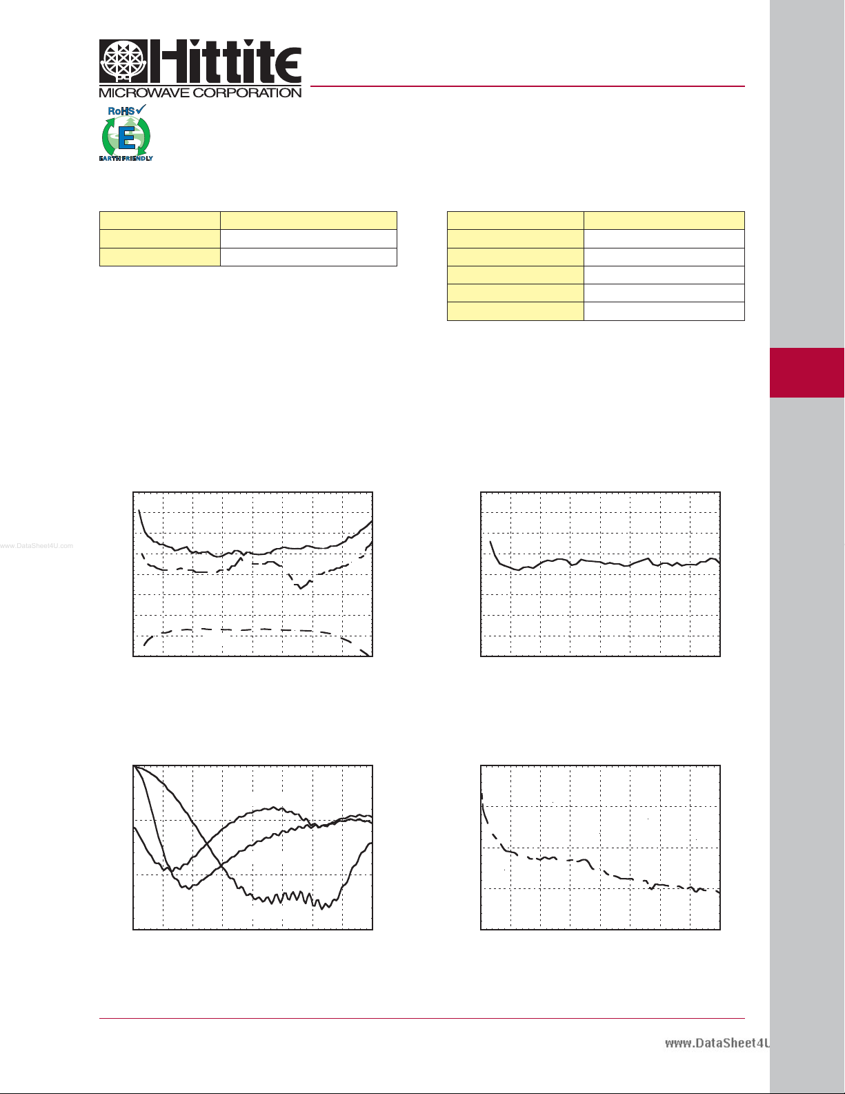
P1dB, Noise Figure, Gain vs. Frequency
30
25
20
15
10
5
0
-5
NF (dB), P1dB (dBm) & GAIN (dB)
-10
0 0.5 1 1.5 2 2.5 3 3.5 4
NF
P1dB
GAIN
RF FREQUENCY (GHz)
AC Test Conditions
Parameter Condition
RF Input Frequency 1970 MHz
RF Input Frequency for IIP3 1970 & 1971 MHz
RF Input Power for IIP3 0 dBm per Tone
LO Frequency 1960 MHz
LO Input Power 0 dBm single ended through LOP
[1]
Input IP3 vs. Frequencya
40
35
30
25
20
15
INPUT IP3 (dBm)
10
5
0
0 0.3 0.6 0.9 1.3 1.6 1.9 2.2 2.5
RF FREQUENCY (GHz)
9
DEMODULATORS - SMT
RF Return Loss vs. Frequency LO & Return Loss vs. Frequency
0
C26=0pF
-5
C26=6.8pF
-10
RF RETURN LOSS (dB)
C26=0.9pF
-15
0 0.5 1 1.5 2 2.5 3 3.5 4
RF FREQUENCY (GHz)
For price, delivery, and to place orders, please contact Hittite Microwave Corporation:
20 Alpha Road, Chelmsford, MA 01824 Phone: 978-250-3343 Fax: 978-250-3373
Order On-line at www.hittite.com
0
-5
-10
RETURN LOSS (dB)
-15
-20
0 0.5 1 1.5 2 2.5 3 3.5 4
RF FREQUENCY (GHz)
9 - 43
Page 3
www.DataSheet4U.com
9
LO - RF Isolation vs. Frequency
0
-20
-40
-60
LO-RF ISOLATION (dB)
-80
-100
0 0.5 1 1.5 2 2.5 3 3.5 4
RF FREQUENCY (GHz)
v00.0806
HMC597LP4 / 597LP4E
SiGe WIDEBAND DIRECT
DEMODULATOR RFIC, 100 - 4000 MHz
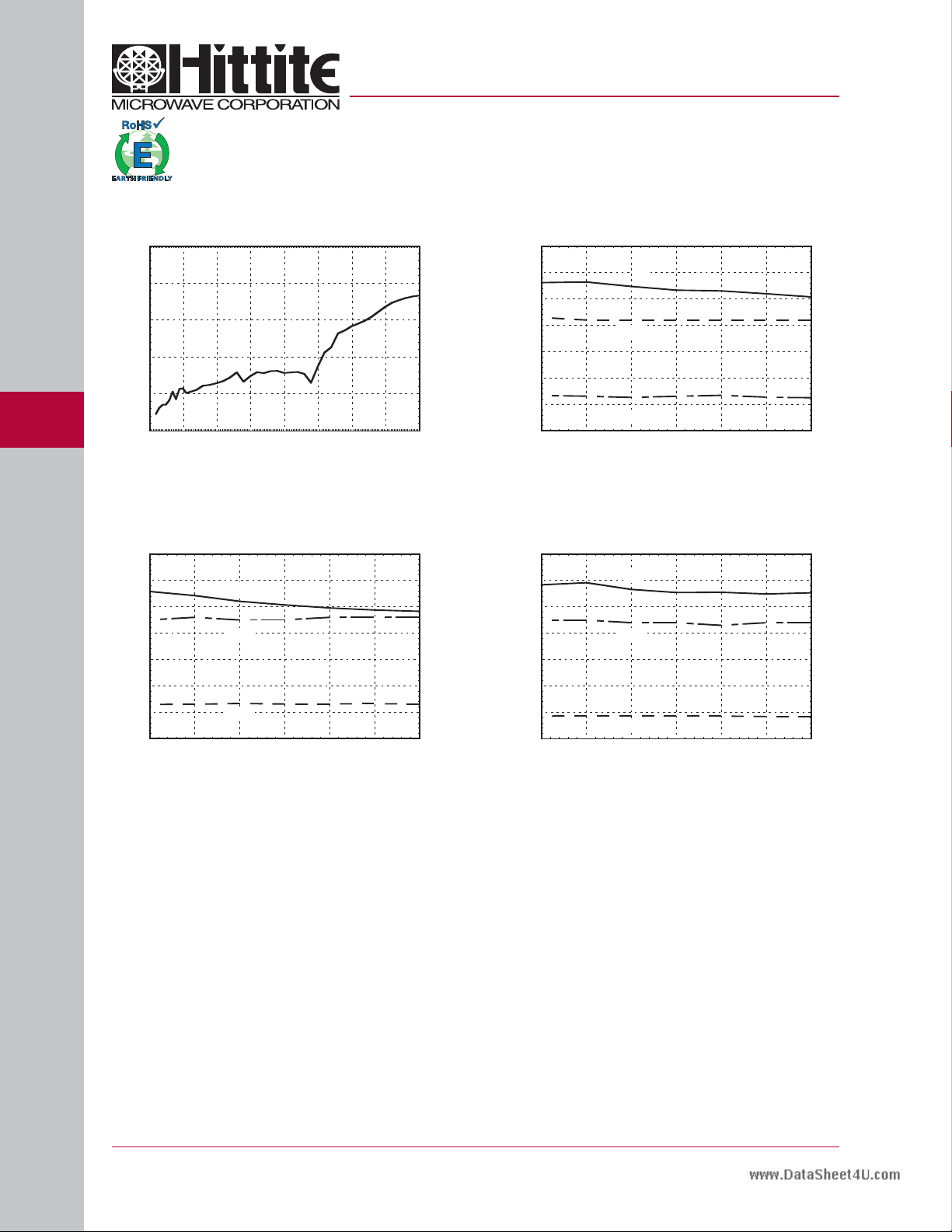
Noise Figure, P1dB,
Gain @ 900 MHz vs. LO Power
25
20
15
10
5
0
-5
NF (dB), P1dB (dBm) & GAIN (dB)
-10
-9 -6 -3 0 3 6 9
NF
P1dB
GAIN
LO POWER (dBm)
DEMODULATORS - SMT
Noise Figure, P1dB,
Gain @ 1970 MHz vs. LO Power
25
20
15
10
5
0
-5
NF (dB), P1dB (dBm) & GAIN (dB)
-10
-9 -6 -3 0 3 6 9
NF
P1dB
GAIN
LO POWER (dBm)
Noise Figure, P1dB,
Gain @ 3500 MHz vs. LO Power
25
20
15
10
5
0
-5
NF (dB), P1dB (dBm) & GAIN (dB)
-10
-9 -6 -3 0 3 6 9
NF
P1dB
GAIN
LO POWER (dBm)
9 - 44
For price, delivery, and to place orders, please contact Hittite Microwave Corporation:
20 Alpha Road, Chelmsford, MA 01824 Phone: 978-250-3343 Fax: 978-250-3373
Order On-line at www.hittite.com
Page 4

www.DataSheet4U.com
Absolute Maximum Ratings
Vcc1, Vc c2 0V to +6V
LO Input Power +12 dBm
Channel Temperature 150 °C
Continuous Pdiss (T = 85°C)
(Derate 30 mW/°C above 85°C)
Thermal Resistance (R
(junction to lead)
Storage Temperature TBD
Operating Temperature -40 to +85 °C
)
th
1.8 Watts
TBD
HMC597LP4 / 597LP4E
v00.0806
SiGe WIDEBAND DIRECT
DEMODULATOR RFIC, 100 - 4000 MHz
ELECTROSTATIC SENSITIVE DEVICE
OBSERVE HANDLING PRECAUTIONS
9
Outline Drawing
NOTES:
1. LEADFRAME MATERIAL: COPPER ALLOY
2. DIMENSIONS ARE IN INCHES [MILLIMETERS].
3. LEAD SPACING TOLERANCE IS NON-CUMULATIVE
4. PAD BURR LENGTH S HALL BE 0.15mm MAXIMUM.
PAD BURR HEIGH T SHALL BE 0.05mm MA XIMUM.
5. PACKAGE WARP SH ALL NOT EXCEED 0.05mm.
6. ALL GROUND LEADS A ND GROUN D PADDLE MUST
BE SOLDER ED TO PCB RF GRO UND.
7. REFER TO HITTITE APPL ICATION NOTE FOR SU GGESTED
PCB LAN D PATTERN.
Package Information
Part Number Package Body Material Lead Finish MSL Rating Package Marking
HMC597LP4 Low Stress Injection Molded Plastic Sn/Pb Solder
HMC597LP4E RoHS- compliant Low Stress Injection Molded Plastic 100% matte Sn
[1] Max peak re ow temperature of 235 °C
[2] Max peak re ow temperature of 260 °C
[3] 4-Digit lot number XXXX
MSL1
MSL1
[1]
[2]
DEMODULATORS - SMT
[3]
H597
XXXX
H597
XXXX
For price, delivery, and to place orders, please contact Hittite Microwave Corporation:
20 Alpha Road, Chelmsford, MA 01824 Phone: 978-250-3343 Fax: 978-250-3373
Order On-line at www.hittite.com
9 - 45
Page 5

www.DataSheet4U.com
v00.0806
DEMODULATOR RFIC, 100 - 4000 MHz
Pin Descriptions
Pin Number Function Description
1 VccLO Supply for LO Ampli er. Draws 109mA @ 2.8V.
HMC597LP4 / 597LP4E
SiGe WIDEBAND DIRECT
9
DEMODULATORS - SMT
2, 5, 8, 11,
12, 14, 17, 19,
20, 23
3LOP
4LON
6, 7, 24 N/C Not Connected
9, 10
21, 22
GND
QN, QP
IP, IN
These pins and the ground paddle should be
connected to a high quality RF/DC ground.
LO inputs. Need DC decoupling capacitors.
1.5 - 1.8 VDC.
These pins should be AC grounded.
Also can be used to optimize the IP2
performances
Differential baseband outputs. 400 Ohms
differential
output impedance. Each port should draw 38 mA
@ 3.5V.
9 - 46
12, 19 VccQ, VccI Decoupling for the Q and I mixer stages.
13, 18 CTRFQ, CTRFI
Center tape of the RF transformer. Should be
connected to a high quality RF/DC ground.
For price, delivery, and to place orders, please contact Hittite Microwave Corporation:
20 Alpha Road, Chelmsford, MA 01824 Phone: 978-250-3343 Fax: 978-250-3373
Order On-line at www.hittite.com
Page 6

www.DataSheet4U.com
v00.0806
Pin Descriptions (Continued)
Pin Number Function Description
15 RFN
16 RFP
RF Input. Can me matched to 50 Ohms
anywhere from 100 - 4000 MHz vias
a capacitor in RFP pin.
Can be DC or RF grounded. This pin is used to
match the RF port over the desired frequency
range. Also can be used to drive the RF port
differentially is needed.
HMC597LP4 / 597LP4E
SiGe WIDEBAND DIRECT
DEMODULATOR RFIC, 100 - 4000 MHz
9
For price, delivery, and to place orders, please contact Hittite Microwave Corporation:
20 Alpha Road, Chelmsford, MA 01824 Phone: 978-250-3343 Fax: 978-250-3373
Order On-line at www.hittite.com
DEMODULATORS - SMT
9 - 47
Page 7

www.DataSheet4U.com
9
HMC597LP4 / 597LP4E
v00.0806
SiGe WIDEBAND DIRECT
DEMODULATOR RFIC, 100 - 4000 MHz
Evaluation PCB
DEMODULATORS - SMT
9 - 48
Evaluation PCB 113785
[1] Reference this number when ordering complete evaluation PCB
[2] Circuit Board Material: Rogers 4350
For price, delivery, and to place orders, please contact Hittite Microwave Corporation:
20 Alpha Road, Chelmsford, MA 01824 Phone: 978-250-3343 Fax: 978-250-3373
[1][2]
Order On-line at www.hittite.com
The circuit board used in the nal application should
use RF circuit design techniques. Signal lines
should have 50 ohm impedance while the package
ground leads and exposed paddle should be connected directly to the ground plane similar to that
shown. A suf cient number of via holes should be
used to connect the top and bottom ground planes.
The evaluation circuit board shown is available from
Hittite upon request.
Page 8

www.DataSheet4U.com
v00.0806
DEMODULATOR RFIC, 100 - 4000 MHz
Application & Evaluation PCB Schematic
HMC597LP4 / 597LP4E
SiGe WIDEBAND DIRECT
9
For price, delivery, and to place orders, please contact Hittite Microwave Corporation:
20 Alpha Road, Chelmsford, MA 01824 Phone: 978-250-3343 Fax: 978-250-3373
Order On-line at www.hittite.com
DEMODULATORS - SMT
9 - 49
 Loading...