


Quick Installation Guide
EASYZONE
Español
English
Français
Italiano
Português
Deutsch
rebmuNegaPdraobpilC


3
ES
EN
FR
IT
PT
DE
ÍNDICE
Precauciones y política medioambiental .............................................................................................................................................................................................. 4
Precauciones ............................................................................................................................................................................................................................................ 4
Política medioambiental....................................................................................................................................................................................................................... 4
Requisitos generales .................................................................................................................................................................................................................................... 5
Elementos del sistema ................................................................................................................................................................................................................................. 6
Central del sistema Innobus Pro6 (AZCE6IBPRO6) ....................................................................................................................................................................... 6
Características técnicas ................................................................................................................................................................................................................... 6
Pasarela de comunicación Daikin (AZX6GTCDA1) ....................................................................................................................................................................... 7
Características técnicas ................................................................................................................................................................................................................... 7
Termostato inteligente Blueface (AZCE6BLUEFACEC) ................................................................................................................................................................ 7
Características técnicas ................................................................................................................................................................................................................... 8
Termostato Think radio (AZCE6THINKR) .......................................................................................................................................................................................... 8
Características técnicas ................................................................................................................................................................................................................... 8
Termostato Lite radio (AZCE6LITER) ................................................................................................................................................................................................. 9
Características técnicas ................................................................................................................................................................................................................... 9
Plenum motorizado estándar (AZEZDAIST) .................................................................................................................................................................................... 9
Plenum motorizado baja silueta (AZEZ6DAISL) ......................................................................................................................................................................... 10
Instalación del sistema ............................................................................................................................................................................................................................. 10
Montaje del sistema .................................................................................................................................................................................................................................. 11
Montaje Easyzone ................................................................................................................................................................................................................................ 11
Montaje a unidad interior.................................................................................................................................................................................................................. 11
Montaje de compuerta bypass ........................................................................................................................................................................................................ 12
Montaje de toma de aire de ventilación ....................................................................................................................................................................................... 12
Sustitución motor ................................................................................................................................................................................................................................ 13
Montaje termostatos (AZCE6BLUEFACEC / AZCE6THINKR / AZCE6LITER) ......................................................................................................................... 14
Conexión a unidad interior ..................................................................................................................................................................................................................... 14
Montaje del sistema .................................................................................................................................................................................................................................. 15
Central del sistema Innobus Pro6 (AZCE6IBPRO6) .................................................................................................................................................................... 15
Reset del sistema ........................................................................................................................................................................................................................... 16
Cambio de batería ......................................................................................................................................................................................................................... 16
Comprobación de montaje y conexión ........................................................................................................................................................................................ 16
Configuración inicial ................................................................................................................................................................................................................................. 16
termostatos Blueface y Think ........................................................................................................................................................................................................... 16
Termostato Lite .................................................................................................................................................................................................................................... 18
Reset termostato Lite ................................................................................................................................................................................................................... 19
Comprobación de configuración inicial ....................................................................................................................................................................................... 19
Regulación de caudal ................................................................................................................................................................................................................................ 20
Ajuste de caudal (REG) ....................................................................................................................................................................................................................... 20
Ajuste de aire mínimo (A-M) ............................................................................................................................................................................................................. 20
Configuración avanzada ................................ ................................................................................................................................................................ .......................... 21
Parámetros de sistema ....................................................................................................................................................................................................................... 21
Parámetros de zona ............................................................................................................................................................................................................................ 22
Autodiagnóstico ......................................................................................................................................................................................................................................... 23
Central de sistema Innobus Pro6 (AZCE6IBPRO6) ..................................................................................................................................................................... 23
Pasarela de comunicación Daikin (AZX6GTCDA1) .................................................................................................................................................................... 23
Termostatos Blueface y Think (AZCE6BLUEFACEC / AZCE6THINKR) ................................................................................................................................... 24
Termostato Lite radio (AZCE6LITER) .............................................................................................................................................................................................. 24
4
ES
EN
FR
IT
PT
DE
PRECAUCIONES Y POLÍTICA MEDIOAMBIENTAL
PRECAUCIONES
Por su seguridad y la de los dispositivos, respete las siguientes instrucciones:
• No manipule el sistema con las manos mojadas ni húmedas.
• Realice todas las conexiones o desconexiones con el sistema de climatización sin alimentar.
• Tenga precaución de no realizar ningún cortocircuito en ninguna conexión del sistema.
POLÍTICA MEDIOAMBIENTAL
No tire nunca este equipo con los desechos domésticos. Los productos eléctricos y
electrónicos contienen sustancias que pueden ser dañinas para el medioambiente si no se les
da el tratamiento adecuado. El símbolo del contenedor de basura tachado indica la recogida
selectiva de aparatos eléctricos, diferenciándose del resto de basuras urbanas. Para una
correcta gestión ambiental, deberá ser llevado a los centros de recogida previstos, al final de
su vida útil.
Las piezas que forman parte del mismo se pueden reciclar. Respete, por tanto, la
reglamentación en vigor sobre protección medioambiental.
Debe entregarlo a su distribuidor si lo reemplaza por otro, o depositarlo en un centro de
recogida especializado.
Los infractores están sujetos a las sanciones y a las medidas que establece la Ley sobre
protección del medio ambiente.
Para acceder a toda la documentación técnica, autodiagnósticos, preguntas frecuentes, vídeos de
montaje y configuración del sistema y certificados, acceda al apartado de Productos de la web
Myzone: myzone.airzone.es/productos/
Para acceder a nuestra declaración de conformidad, consulte:
http://doc.airzone.es/producto/Gama_AZ6/Airzone/Certificados/Declarat
ion_of_conformity_AZ6.pdf
Por el presente, Corporación Empresarial Altra, S.L., declara que AZEZ6DAIxxxxxxx cumple con los requisitos básicos y otras
disposiciones relevantes de la directiva 2014/53/EU.
5
ES
EN
FR
IT
PT
DE
REQUISITOS GENERALES
Siga estrictamente las indicaciones expuestas en este manual:
• El sistema debe ser instalado por un técnico cualificado.
• Compruebe que las unidades a controlar han sido instaladas según los requisitos del fabricante y funcionan
correctamente antes de instalar el sistema Airzone.
• Ubique y conecte todos los elementos de su instalación conforme a la reglamentación electrónica local vigente.
• Compruebe que la instalación de climatización a controlar cumple con la normativa local vigente.
• Es necesario el uso de un termostato Blueface para disponer de todas las funcionalidades del sistema Airzone.
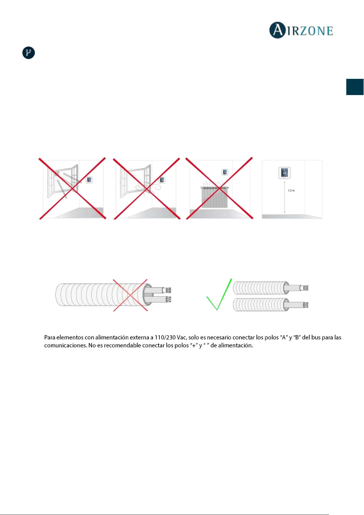
• Siga las siguientes recomendaciones para la ubicación de los termostatos:
• Realice todas las conexiones con ausencia total de alimentación.
• Para la conexión de comunicación con el sistema, utilice el cable Airzone, cable formado por 4 hilos (2x 0.22 mm2 hilos
trenzados y apantallados para la comunicación de datos y 2x0.5 mm2 hilos para la alimentación).
• No sitúe el bus del sistema junto a líneas de fuerza, fluorescentes, motores, etc., que puedan generar interferencias en
las comunicaciones.
• Respete la polaridad de conexión de cada dispositivo. Una conexión errónea puede dañar seriamente el producto.
•
-
• Para elementos con alimentación externa a 110/230 Vac, respete la polaridad de conexión. Una conexión a tierra
incorrecta puede provocar descargas eléctricas.
• En el cableado de alimentación externo del sistema deberá incorporarse, según la reglamentación local y nacional
pertinente, un interruptor principal u otro medio de desconexión que tenga una separación constante en todos los
polos. El sistema se reiniciará automáticamente si se apaga la alimentación principal. Utilice un circuito
independiente del equipo a controlar para la alimentación del sistema.
• Una vez configurado el sistema Airzone, compruebe que la presión estática en el equipo de conductos está acorde
con las condiciones de la red de distribución de aire donde esté instalado (consulte el manual del fabricante del equipo
si necesita modificar este parámetro).
6
ES
EN
FR
IT
PT
DE
ELEMENTOS DEL SISTEMA
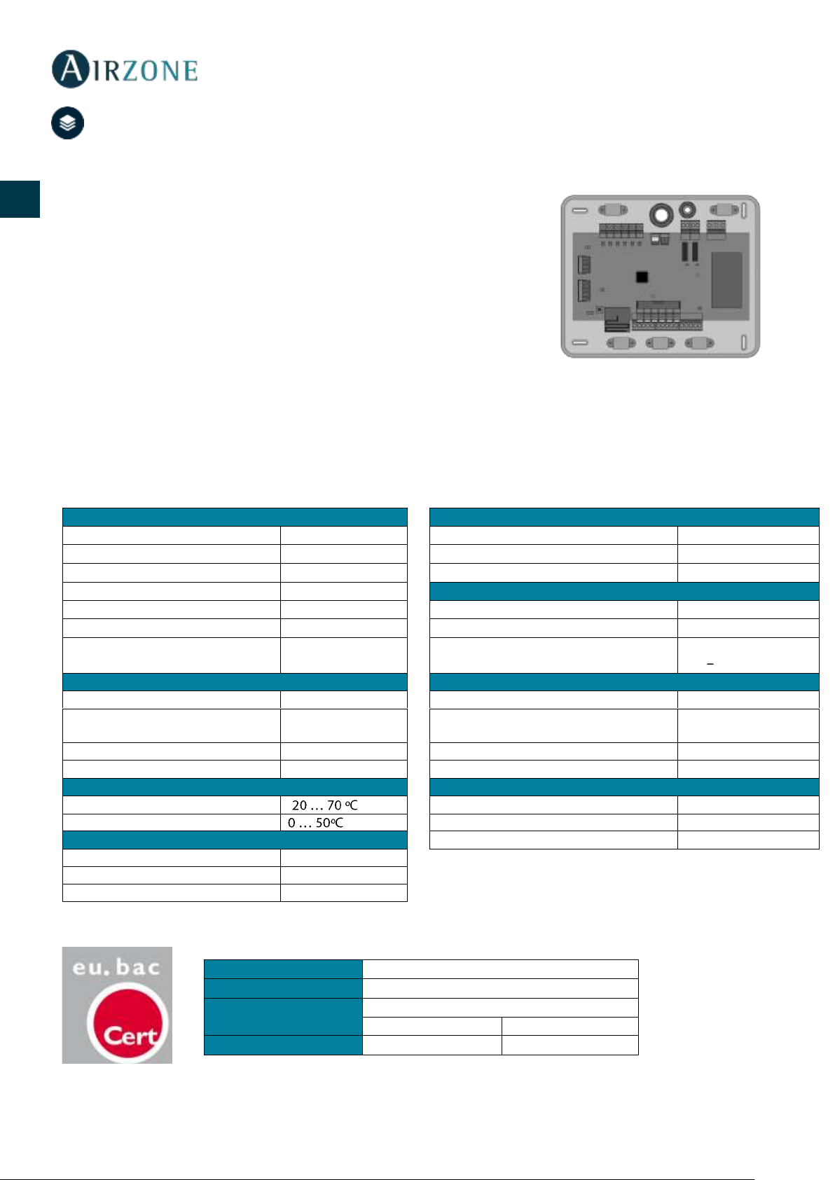
CENTRAL DEL SISTEMA INNOBUS PRO6 (AZCE6IBPRO6)
Equipo electrónico encargado de hacer la gestión del sistema, mediante dispositivos
cableados e inalámbricos. Montaje en superficie.
Funcionalidades:
• Control y gestión del estado de los termostatos, hasta 6 zonas.
• Salidas de alimentación para elementos motorizados.
• Módulo de control On/Off zona remota, hasta 6 zonas.
• Salida de relé configurable como ventilación mecánica (VMC) o caldera.
• Gestión de pasarelas de control a equipos de climatización.
• Comunicación con equipos de control integral de la instalación.
• Comunicaciones con otros sistemas de control externo mediante bus de integración.
Características técnicas
Alimentación y consumo
Bus de conexión Airzone
Tipo de alimentación
Vac
Nº de puertos
3
V max
110 / 230 V
Cable apantallado y trenzado
2 x 0,22 + 2x0,5 mm2
I max
250 mA
V max
12 V
Frecuencia
60/50 Hz
Bus domótico
Consumo Stand-by
400 mW
Nº de puertos
1
Consumo máximo
25 W
Cable apantallado y trenzado
2 x 0,22 + 2x0,5 mm2
Protección sobre corriente módulo
250 mA
Protocolo de comunicaciones
MODBUS RS-485
Par 19200 bps
Comunicaciones vía radio
Salidas de motor
Protocolo de comunicaciones
Airzone
Nº de salidas
6
Frecuencia
868 MHz
Nº máximo de motorizaciones por
salidas
2
Potencia de radiación
5 dBm
Vmax
± 12 V
Distancia máxima en espacio libre
40 m
Imax
150 mA
Temperaturas operativas
Salidas de relé
Almacenaje
-
Nº de relés
2
Funcionamiento V max
24 / 48 V
Aspectos mecánicos
I max
1 A
Grado de protección
IP 20
Peso
616 g
Dimensiones (WxHxD)
195x180x55,5 mm
Type
Airzone Central V1.3
Licence
215562
Application
Variable air volume system (without h/c coil)
Heating
Cooling
Control accuracy (K)
0.3
0.3
7
ES
EN
FR
IT
PT
DE
PASARELA DE COMUNICACIÓN DAIKIN (AZX6GTCDA1)
Pasarela para la gestión de equipos de A/A Daikin compatibles mediante los sistemas de control
Airzone. Alimentación mediante unidad interior. Montaje y conexión sobre puerto de máquina
de los dispositivos Airzone habilitados. Producto desarrollado y testeado junto con el fabricante.
Funcionalidades:
• Comunicación bidireccional de los parámetros básicos de control en función de la demanda
del sistema de control Airzone.
• Control de hasta 5 velocidades de forma automática, permitiendo (en general) el
funcionamiento sin bypass.
• Ajuste de la temperatura de consigna en función de las temperaturas seleccionadas en los
termostatos Airzone y del algoritmo Eco-Adapt.
• Lectura de la temperatura de trabajo del equipo.
• Lectura de avisos y errores del equipo controlado.
• Control maestro de la unidad.
Características técnicas
TERMOSTATO INTELIGENTE BLUEFACE (AZCE6BLUEFACEC)
Interfaz gráfico a color con pantalla capacitiva y acabado en acero y cristal, para el control de zona en un sistema Airzone.
Alimentado a través de la central del sistema. Disponible en blanco y negro.
Funcionalidades:
• 6 idiomas disponibles (Español, Inglés, Francés, Italiano, Alemán y Portugués).
• Control de temperatura, modo de funcionamiento (termostato maestro) y velocidad
del ventilador (termostato maestro e instalación Fan coil).
• Lectura de temperatura ambiente y humedad relativa de zona.
• Función Eco-Adapt.
• Función Sleep.
• Programaciones horarias de temperatura y modo.
• Acceso remoto a otras zonas del sistema.
Alimentación y consumo
Alimentación
Unidad interior
V max
12 Vdc
I max
30 mA
Comunicaciones
Tipo de cable
Trenzado y apantallado
Hilos de comunicación
2 x 0,5 mm2
Temperaturas operativas
Almacenaje
-
Funcionamiento
8
ES
EN
FR
IT
PT
DE
Características técnicas
TERMOSTATO THINK RADIO (AZCE6THINKR)
Interfaz gráfico con pantalla de tinta de bajo consumo, botones capacitivos y acabado en acero y cristal, para el control de zona
en un sistema Airzone. Comunicaciones vía radio. Alimentado mediante batería de botón CR2450. Disponible en blanco y
negro.
Funcionalidades:
• 6 idiomas disponibles (Español, Inglés, Francés, Italiano, Alemán y Portugués).
• Control de temperatura, modo de funcionamiento (termostato maestro) y velocidad
del sistema (termostato maestro e instalación Fan coil).
• Lectura de temperatura ambiente y humedad relativa de zona.
• Función Sleep.
• Acceso remoto a otras zonas del sistema.
Características técnicas
Alimentación y consumo
Temperaturas operativas
Tipo de alimentación
Vdc
Almacenaje
-
V max
12 V
Funcionamiento
I max
145 mA
Rango de temperatura de consigna
Consumo Stand-by
0,876 W
Precisión de lectura
±0,1 ºC
Consumo máximo
1,74 W
Precisión de representación
±0,1 ºC
Conexión y comunicaciones
Humedad relativa
±4 %
Tipo de cable
Trenzado y apantallado
Aspectos mecánicos
Hilos de comunicación
2 x 0,22 mm2
Montaje
En superficie mediante soporte
Hilos de alimentación
2 x 0,5 mm2
Grado de protección
IP 20
Distancia máxima
40 m
Tipo de sonda
Airzone_NTC_10K
Peso
198 g
Dimensiones (WxHxD)
92x 92x15,85 mm
Alimentación y consumo
Temperaturas operativas
Tipo de alimentación
Vdc
Almacenaje
-
V max
3,3 V
Funcionamiento
I max
30 mA
Rango de temperatura de consigna
Battery
CR2450
Precisión de lectura
±0,1 ºC
Vida útil de la batería
2 años
Precisión de representación
±0,1 ºC
Consumo Stand-by
0,01 mW
Humedad relativa
±4 %
Consumo máximo
100 mW
Aspectos mecánicos
Conexión y comunicaciones
Montaje
En superficie mediante soporte
Frecuencia de comunicación
868 MHz
Grado de protección
IP 20
Potencia máxima
0 dBm
Tipo de sonda
Airzone_NTC_10K
Distancia máxima en espacio libre
40 m
Peso
180 g
Dimensiones (WxHxD)
92x 92x15,85 mm
9
ES
EN
FR
IT
PT
DE
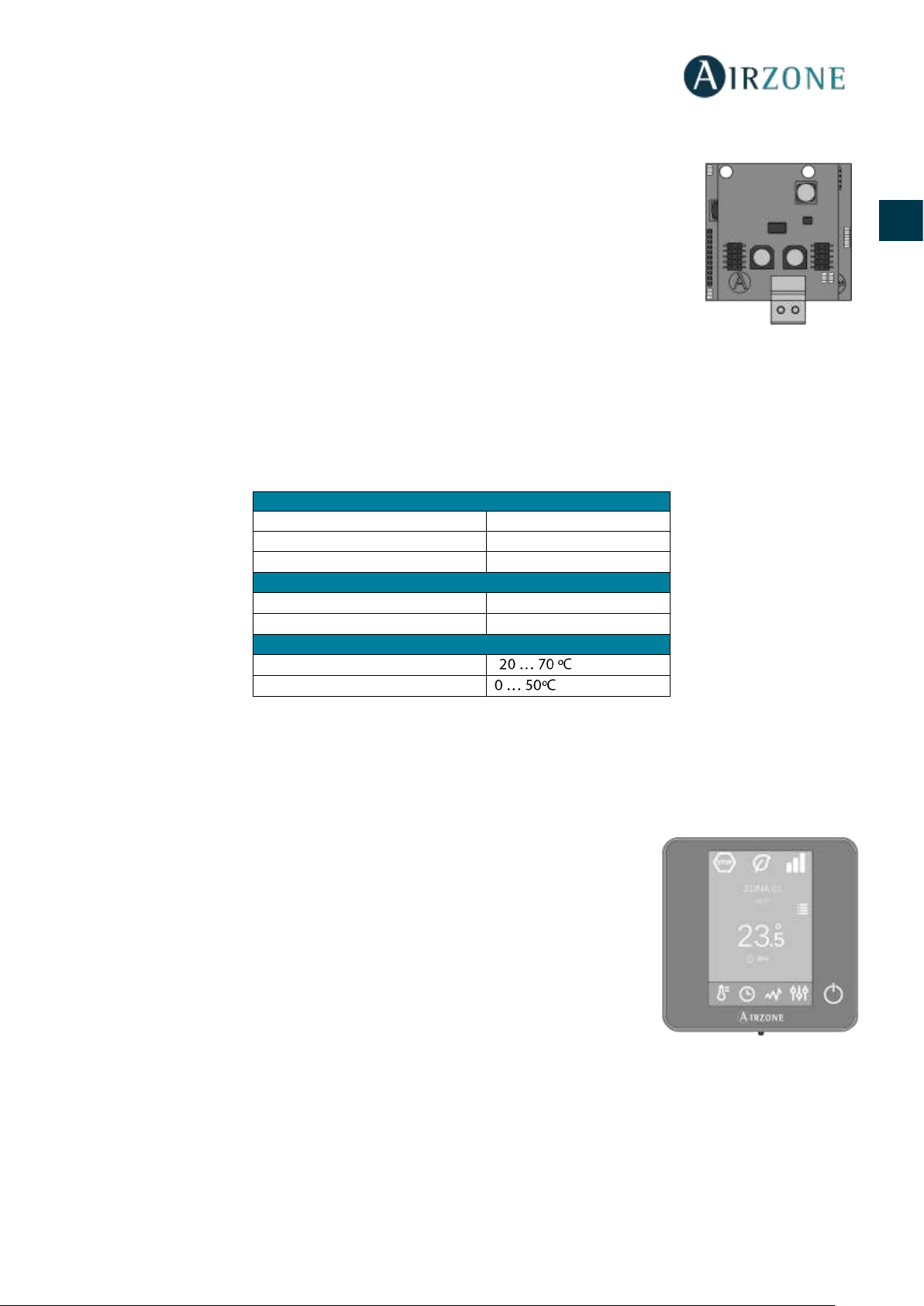
TERMOSTATO LITE RADIO (AZCE6LITER)
Termostato con botones capacitivos y acabado en acero y cristal, para el control de
temperatura de zona en un sistema Airzone. Comunicaciones vía radio. Alimentado
mediante batería de botón CR2450. Disponible en blanco y negro.
Funcionalidades:
• On/Off de la zona.
• Control de temperatura de consigna, en pasos de 1ºC, hasta un máximo de ±3ºC.
• Lectura de la temperatura ambiente y humedad relativa.
Características técnicas
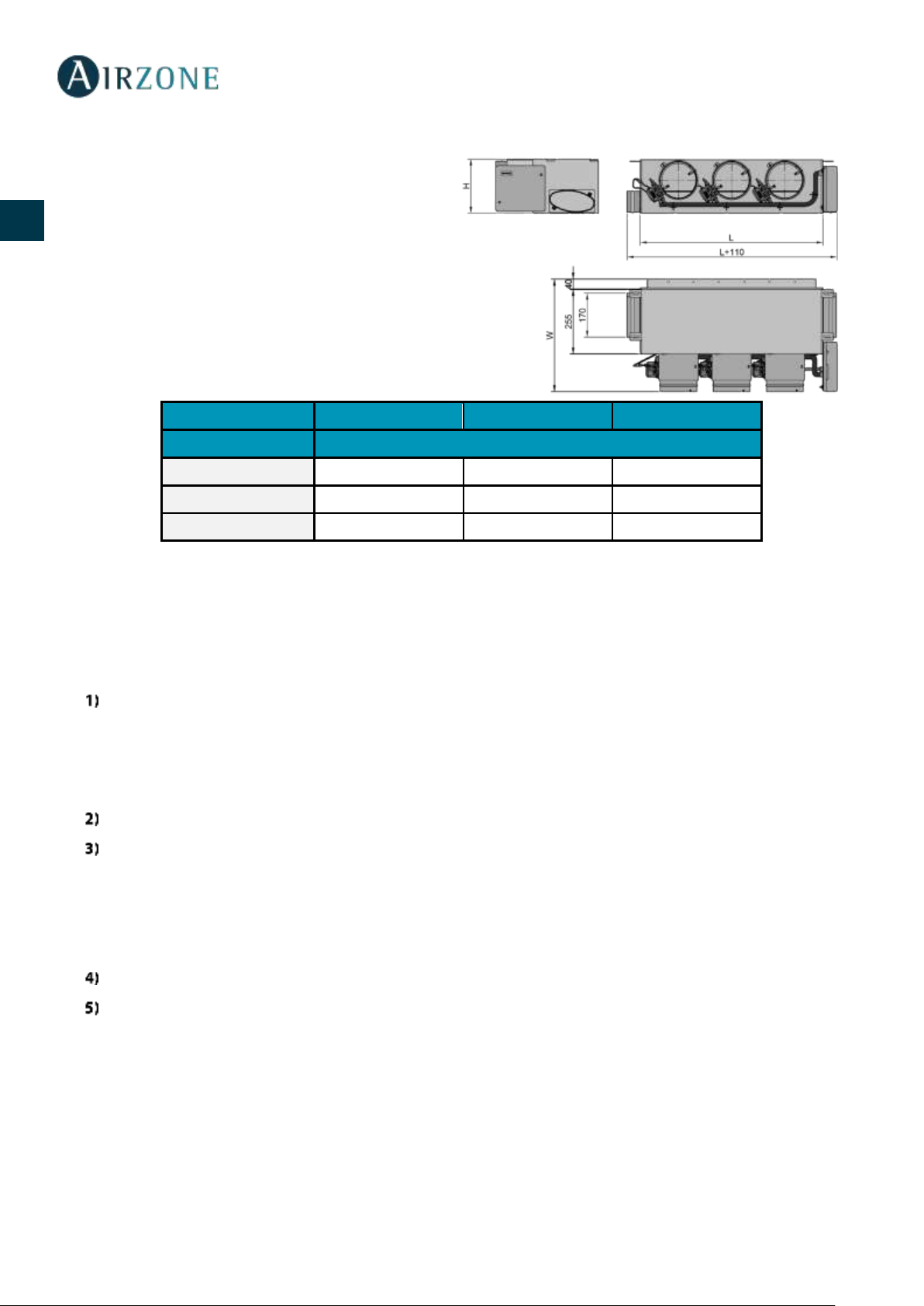
PLENUM MOTORIZADO ESTÁNDAR (AZEZDAIST)
El plenum motorizado estándar Airzone incluye:
- Central del sistema.
- Pasarela de comunicación.
- Compuertas circulares de 200 mm de diámetro.
- Sistema de regulación manual de caudal.
- Entrada para la ventilación mecánica controlada
(VMC), diámetro equivalente de 150 mm.
Variación de hasta ±3 dB(A) sobre el nivel de presión
sonora de la unidad interior y peso máximo 18 Kg.
Talla
XS S M L XL
Nº de
compuertas
L x H x W (mm)
2 / 3
930 x 300 x 454
930 x 300 x 454
4
1140 x 300 x 454
1140 x 300 x 454
5
1425 x 300 x 454
1425 x 300 x 454
1425 x 300 x 454
6
1638 x 300 x 454
1638 x 300 x 454
7 / 8
1425 x 515 x 454
1425 x 515 x 454
Código de Plenum: AZEZ6DAIST07 [Talla] [Nº de compuertas]
Alimentación y consumo
Temperaturas operativas
Tipo de alimentación
Vdc
Almacenaje
-
V max
3,3 V
Funcionamiento
I max
30 mA
Rango de temperatura de consigna
Battery
CR2450
Precisión de lectura
±0,1 ºC
Vida útil de la batería
2 años
Precisión de representación
±0,1 ºC
Consumo Stand-by
0,01 mW
Humedad relativa
±4 %
Consumo máximo
100 mW
Aspectos mecánicos
Conexión y comunicaciones
Montaje
En superficie mediante soporte
Frecuencia de comunicación
868 MHz
Grado de protección
IP 20
Potencia máxima
0 dBm
Tipo de sonda
Airzone_NTC_10K
Distancia máxima en espacio libre
40 m
Peso
184 g
Dimensiones (WxHxD)
92x 92x15,85 mm
10
ES
EN
FR
IT
PT
DE
PLENUM MOTORIZADO BAJA SILUETA (AZEZ6DAISL)
El plenum motorizado de baja silueta Airzone incluye:
- Central del sistema.
- Pasarela de comunicaciones.
- Compuertas circulares de 150 mm de diámetro.
- Sistema de regulación manual de caudal.
- Entrada para la ventilación mecánica controlada
(VMC), diámetro equivalente de 150 mm.
Variación de hasta ±3 dB(A) sobre el nivel de presión
sonora de la unidad interior y peso máximo 18 Kg.
Talla S M
L
Nº de compuertas
L x H x W (mm)
2 / 3
720 x 210 x 444
4
930 x 210 x 444
5
1140 x 210 x 444
Código de Plenum: AZEZ6DAISL01 [Talla] [Nº de compuertas]
INSTALACIÓN DEL SISTEMA
Para realizar una correcta instalación su sistema siga los siguientes pasos:
Realice todas las conexiones eléctricas (Ver apartado Montaje del sistema).
- Conecte la pasarela de comunicación con la unidad interior a controlar.
- Conecte los distintos elementos de los que dispone el sistema (termostatos, módulos, etc.)
- Alimente la central.
Compruebe el correcto montaje y conexión del sistema (Ver apartado Comprobación de montaje y conexión).
Configure el sistema.
- Configure los distintos termostatos del sistema (Ver apartados Configuración inicial y Configuración avanzada).
- Recuerde que los sistemas Airzone permiten la configuración de interfaces maestras y de zonas. Desde un termostato
maestro podrá realizar un cambio de Modo; definir el grado de eficiencia con la función Eco-Adapt o seleccionar las
velocidades en su equipo.
Consulte el manual de usuario e instalación del sistema para cualquier otra consulta.
No requiere mantenimiento.
11
ES
EN
FR
IT
PT
DE
MONTAJE DEL SISTEMA
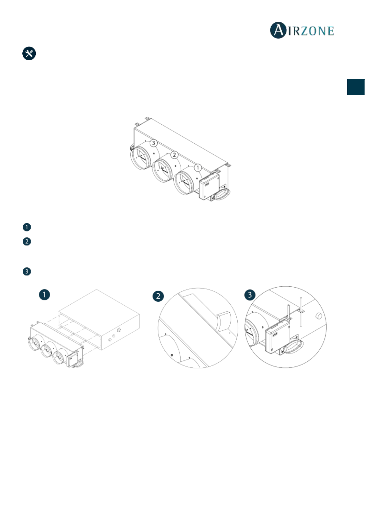
MONTAJE EASYZONE
Importante: Se recomienda aislar todas las partes metálicas del Easyzone que queden en contacto con el exterior para evitar
la aparición de condensación.
Recuerde: Las motorizaciones se encuentran numeradas del siguiente modo:
MONTAJE A UNIDAD INTERIOR
Sitúe el Easyzone en la boca de impulsión del equipo y fíjelo a este mediante tornillos.
Después de fijar los tornillos, asegúrese de aislar el cuello de conexión para evitar la formación de condensación. Utilice
bandas de material aislante (lana de vidrio o de espuma de polietileno) de 25 mm de espesor. La anchura de estas bandas de
aislamiento es de 97 mm para el plenum motorizado estándar y de 36 mm para el plenum motorizado de baja silueta.
Fije el Easyzone al techo a través de las lengüetas de los extremos mediante varillas roscadas.

12
ES
EN
FR
IT
PT
DE
MONTAJE DE COMPUERTA BYPASS
Mediante un golpe seco retire el área precortada de los laterales correspondiente al bypass.
Mediante una cuchilla, retire el aislante que cubre la zona del bypass y descubra las ranuras de fijación del bypass.
Encaje la compuerta de bypass en las ranuras y gire de izquierda a derecha hasta llevar al tope.
Fije la compuerta bypass al plenum mediante un tornillo rosca-chapa (Ø: 3.9mm).
MONTAJE DE TOMA DE AIRE DE VENTILACIÓN
Retire el cuello elíptico fijado mediante tornillos.
Retire la chapa de protección que cubre la toma de aire exterior y vuelva a fijar el cuello elíptico.
Doble o corte la tapa que se encuentra en la parte inferior de las compuertas de impulsión para permitir el paso de aire.
13
ES
EN
FR
IT
PT
DE
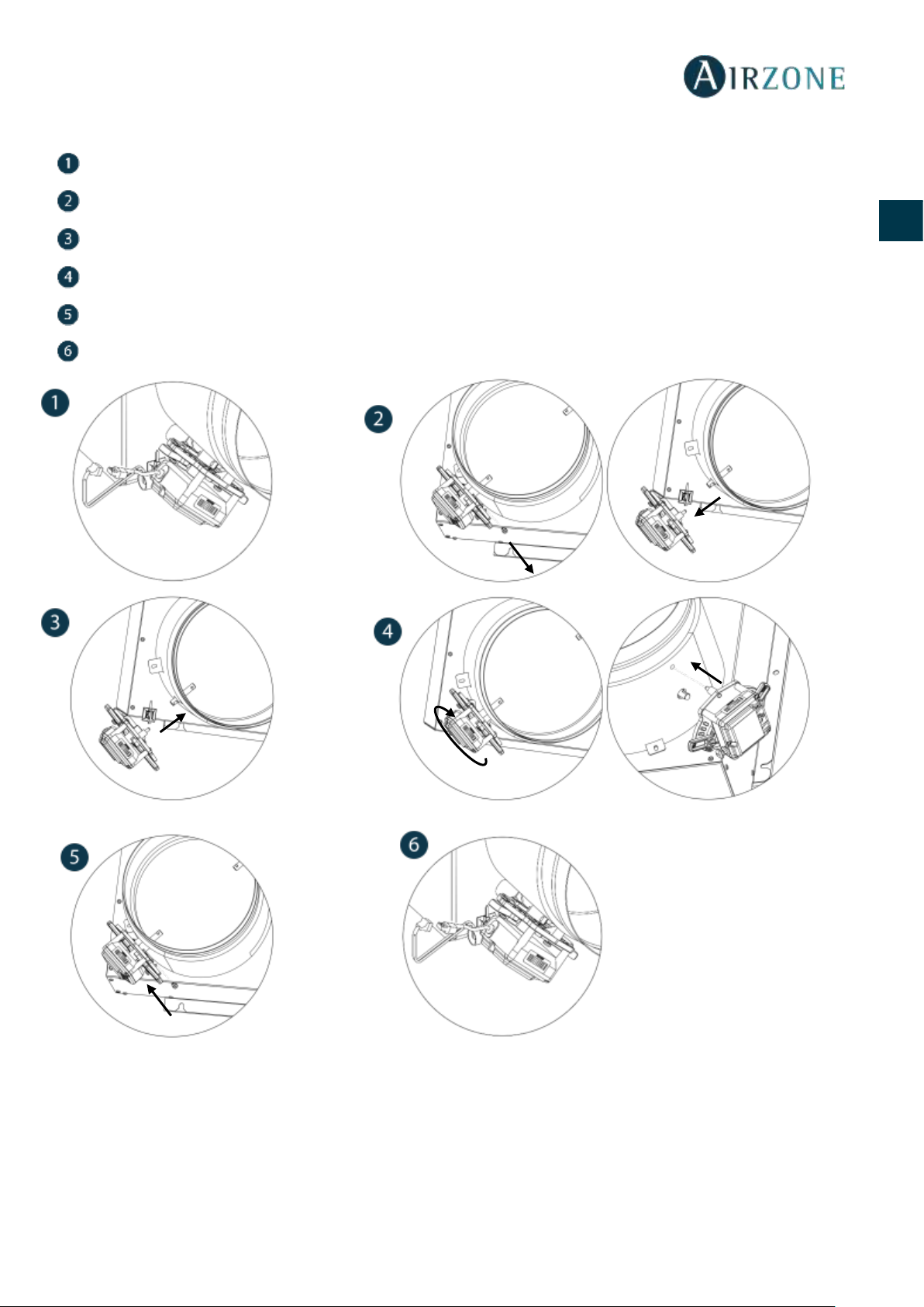
SUSTITUCIÓN MOTOR
Desconecte el motor.
Afloje el tornillo de fijación mediante una llave Allen nº3 y retire el motor de la compuerta.
Coloque el nuevo motor de forma que coincida con el perno.
Gire el motor hasta que coincida el segundo perno con el orificio para que la compuerta quede en la posición correcta.
Inserte y apriete el tornillo de fijación.
Conecte el cable del motor.
14
ES
EN
FR
IT
PT
DE
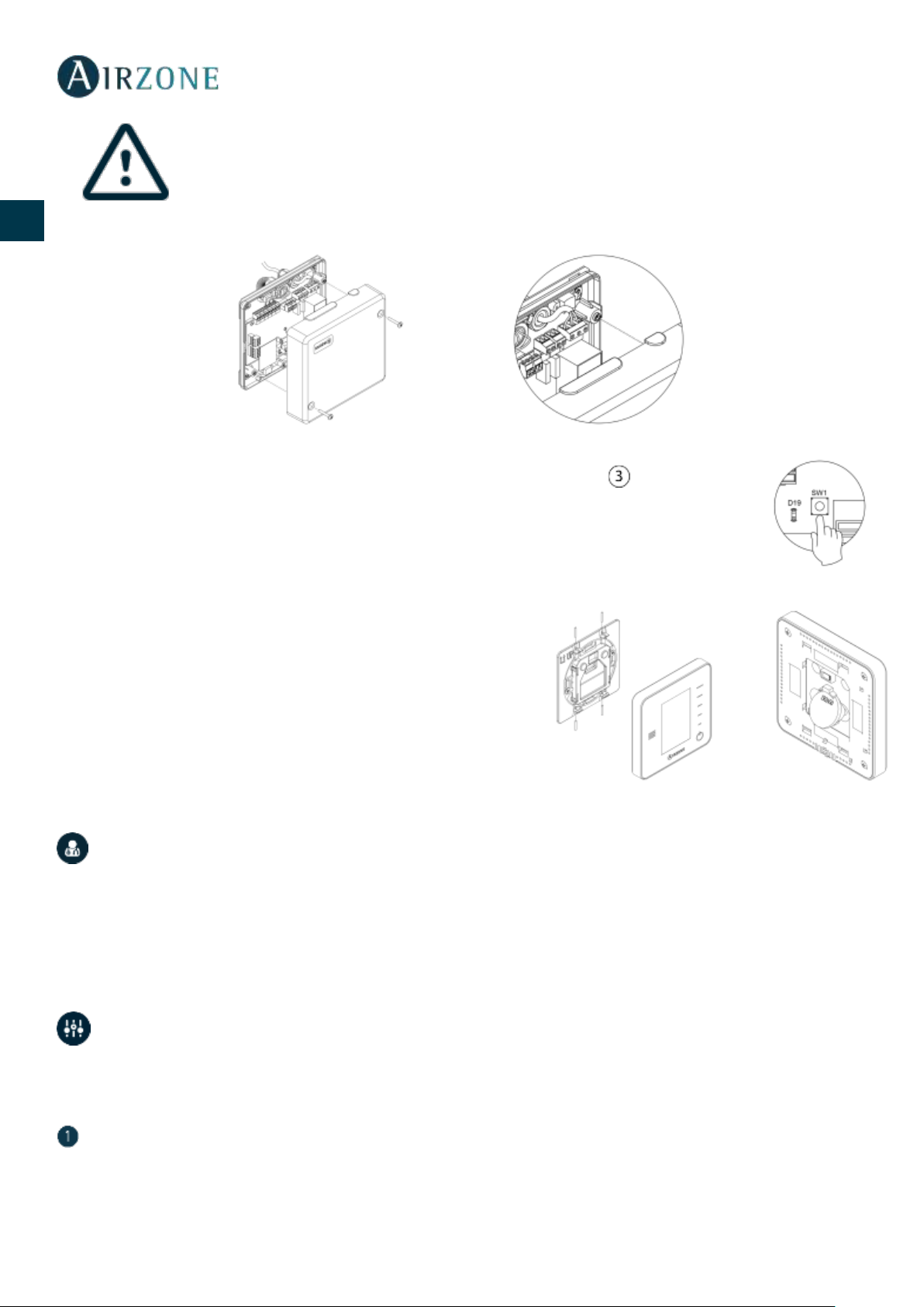
MONTAJE TERMOSTATOS (AZCE6BLUEFACEC / AZCE6THINKR / AZCE6LITER)
Los termostatos de Airzone se montan en superficie mediante soporte. Recuerde que la distancia máxima recomendable para
este dispositivo es de 40 metros. Para su fijación en pared siga los siguientes pasos:
• Separe la parte trasera del termostato y realice las conexiones pertinentes
(AZCE6BLUEFACEC) o introduzca la batería de botón CR2450 (AZCE6THINKR y
AZCE6LITER).
• Fije la parte trasera del termostato en la pared.
• Coloque el display sobre el soporte ya fijado.
• Coloque las varillas anti-vandálicas para una mayor sujeción del termostato
(opcional).
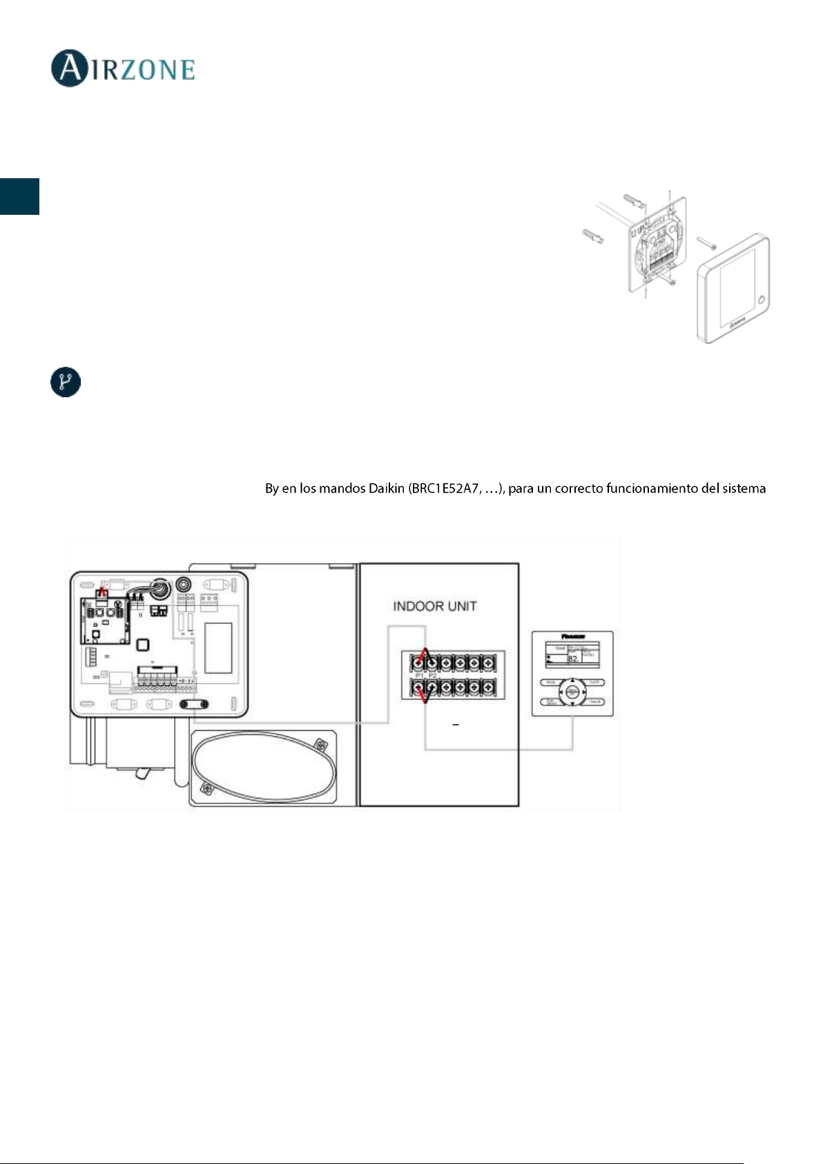
CONEXIÓN A UNIDAD INTERIOR
1) Retire la alimentación de la unidad interior Daikin así como del sistema Airzone.
2) Localice la conexión P1 P2 en la unidad interior de Daikin (donde se conecta el termostato).
3) Conecte la pasarela Airzone al puerto P1 P2 de la unidad interior Daikin, mediante el cable suministrado por Airzone.
4) Alimente la unidad interior y el sistema Airzone. Compruebe los LEDs de la pasarela (ver apartado Autodiagnóstico).
5) Deshabilite la función StandAirzone. Ajus. Servicio > Ajustes de Obra > 1e-2-01. Para cualquier duda, consulte el Manual de Instrucciones Daikin
BRC1E52A7.
P1 Rojo
P2 - Negro
15
ES
EN
FR
IT
PT
DE
MONTAJE DEL SISTEMA
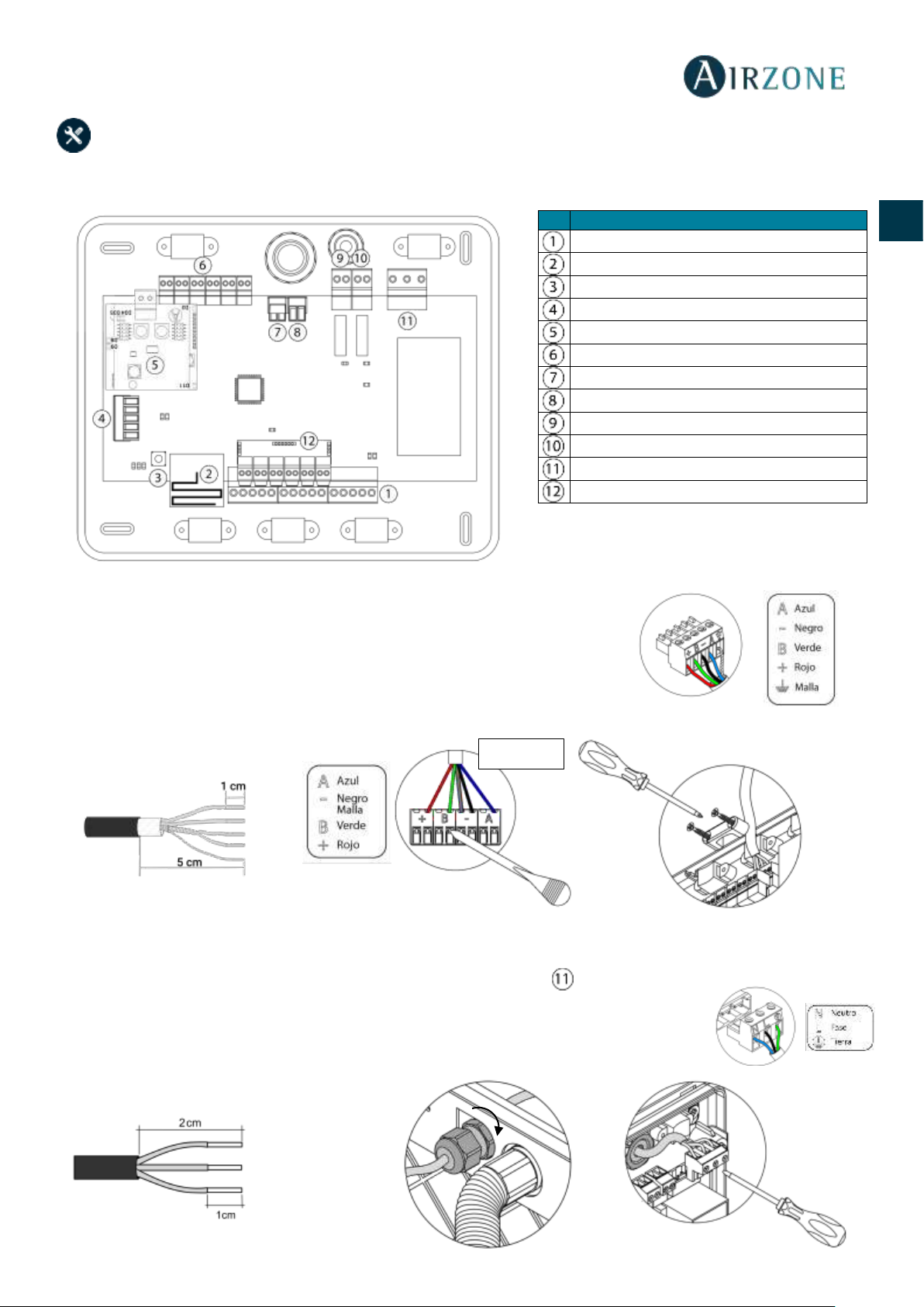
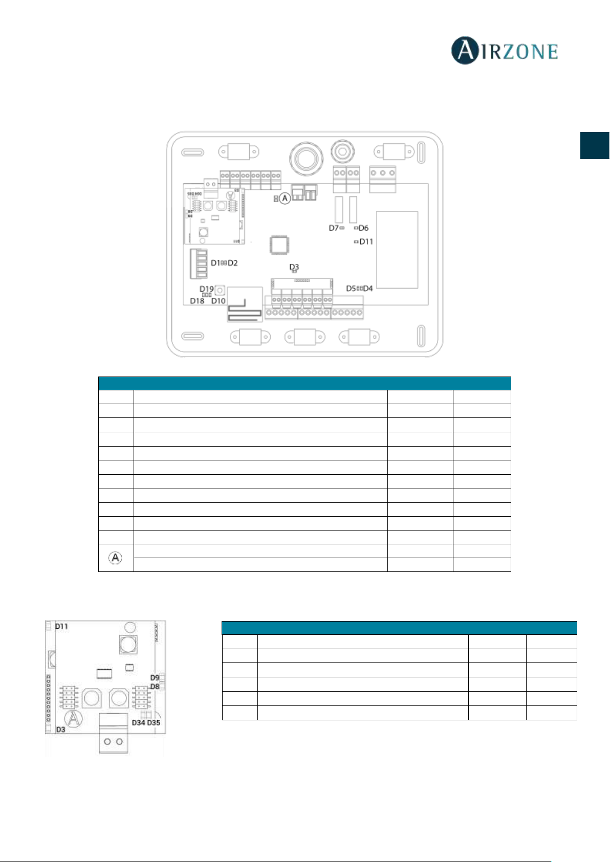
CENTRAL DEL SISTEMA INNOBUS PRO6 (AZCE6IBPRO6)
1.- Conexión de los termostatos
Si su termostato es cable, conéctelo en cualquiera de las 3 bornas del bus de conexión
Airzone. La conexión se puede realizar tanto en modo bus como en estrella. Utilice cable
Airzone de 2x0,5+2x0,22 mm2. Fije los cables en las torretas de la central para mayor
seguridad.
En los termostatos radio, compruebe que se ha insertado la batería.
2.- Alimentación del sistema
Alimente a 110 / 230 Vac la central de sistema por la entrada de alimentación y los elementos de
control que necesiten alimentación externa. Para ello utilice cable de 3x1,5 mm². Para la
alimentación de la central del sistema, afloje la prensaestopa en caso necesario y pase el cable por
el orificio (Ø: 5-10 mm), fije los cables a la borna respetando la polaridad. Conecte la borna a la
entrada de alimentación y apriete la prensaestopa para fijar el cable de alimentación.
Nº
Descripción
Bus de conexión Airzone
Módulo de radio
SW1
Bus domótico
Pasarela Daikin
Salidas de motor
Entrada alarma (normalmente cerrada)
Sonda temperatura
VMC/Caldera
Relé paro-marcha AA
Alimentación
Módulo On/Off
Importante: Para el control de las entradas del
módulo On/Off se debe utilizar cable apantallado.
Termostato
Presione
16
ES
EN
FR
IT
PT
DE
En el cableado de alimentación externo del sistema deberá incorporarse, según la reglamentación local
y nacional pertinente, un interruptor principal u otro medio de desconexión que tenga una separación
constante en todos los polos. El sistema se reiniciará automáticamente si se apaga la alimentación
principal. Utilice un circuito independiente del equipo a controlar para la alimentación del sistema.
Recuerde: Una vez realizadas todas las conexiones, asegúrese de colocar correctamente la tapa de la central de sistema.
Reset del sistema
En caso que necesite devolver el sistema a valores de fábrica, mantenga pulsado SW1 hasta que el LED
D19 deje de parpadear. Espere a que los LED vuelvan a su estado normal para volver a realizar la
configuración inicial.
Cambio de batería
Para sustituir la batería, separe el termostato de su soporte y sustituya la
batería (CR2450).
Importante: Se recomienda el uso de baterías de primeras marcas,
similares a las suministradas. Una batería de menor calidad puede reducir
la vida útil de esta.
Recuerde depositar la batería retirada en un punto de reciclaje adecuado.
Nota: Recuerde retirar el sistema anti-vandálico antes de retirar el termostato
de la pared.
COMPROBACIÓN DE MONTAJE Y CONEXIÓN
Compruebe los siguientes ítems:
- Estado de los LEDs de la central y de los demás elementos de control conectados. Consulte el apartado de
Autodiagnóstico.
- Alimentación de los termostatos cableados y radio.
CONFIGURACIÓN INICIAL
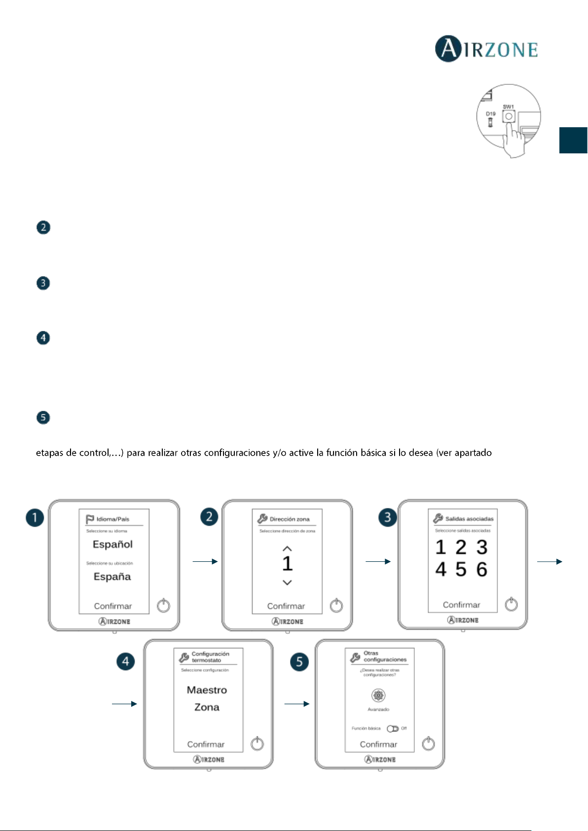
TERMOSTATOS BLUEFACE Y THINK
Importante: Una vez que empiece no podrá volver hacia atrás y deberá terminar todo el proceso de configuración.
Idioma/País
Seleccione el idioma que desee y su ubicación. Los idiomas disponibles son: español, inglés, francés, italiano, portugués y
alemán.
En caso de termostatos Think radio, inicie la búsqueda de canal radio:
17
ES
EN
FR
IT
PT
DE
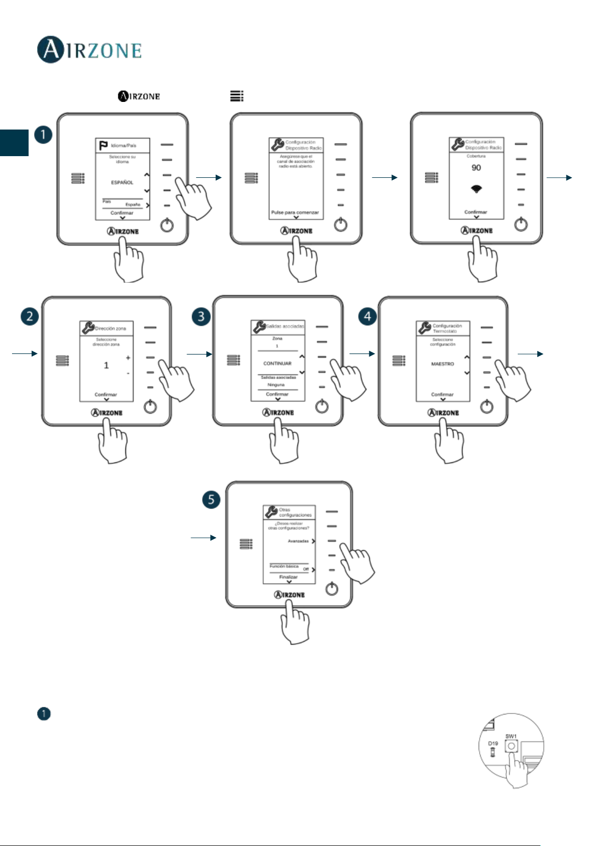
Configuración dispositivo radio
- Abra el canal de asociación radio. Para ello pulse sobre SW1, el LED D19 se encenderá en color
rojo fijo. Una vez abierto dispone de 15 minutos para realizar la asociación, en el caso de que
se le agote el tiempo realice de nuevo esta operación. También puede abrir el canal de
asociación radio a través de los controladores Blueface (ver apartado Parámetros de sistema)
IMPORTANTE: Recuerde no tener más de un canal abierto en la misma instalación de forma
simultánea, puede ocasionar asociaciones erróneas.
- Inicie la búsqueda de canal Radio, para ello pulse Airzone para comenzar la búsqueda.
- Compruebe que la cobertura es óptima (mínimo 30%) y confirme.
Dirección zona
Seleccione la zona asociada a este termostato. A cada zona le corresponde una salida de control. De este modo, por ejemplo,
la zona 1 controlará la salida de motor 1.
Salidas asociadas
El sistema permite asociar a una zona más de una salida de control en caso de necesidad. Siendo posible gestionar varias salidas
de control desde un único termostato.
Configuración termostato
Seleccione el funcionamiento del termostato:
- Maestro: Permite el control de todos los parámetros de la instalación.
- Zona: Permite el control de los parámetros de zona únicamente.
Otras configuraciones
Pulse para finalizar el proceso de configuración inicial, o acceda al menú de configuración avanzada (dirección del sistema,
Configuración
avanzada, Parámetros de zona).
Blueface
18
ES
EN
FR
IT
PT
DE
Think
Importante: Utilice para confirmar y para volver atrás en el caso de que se encuentre en submenús.
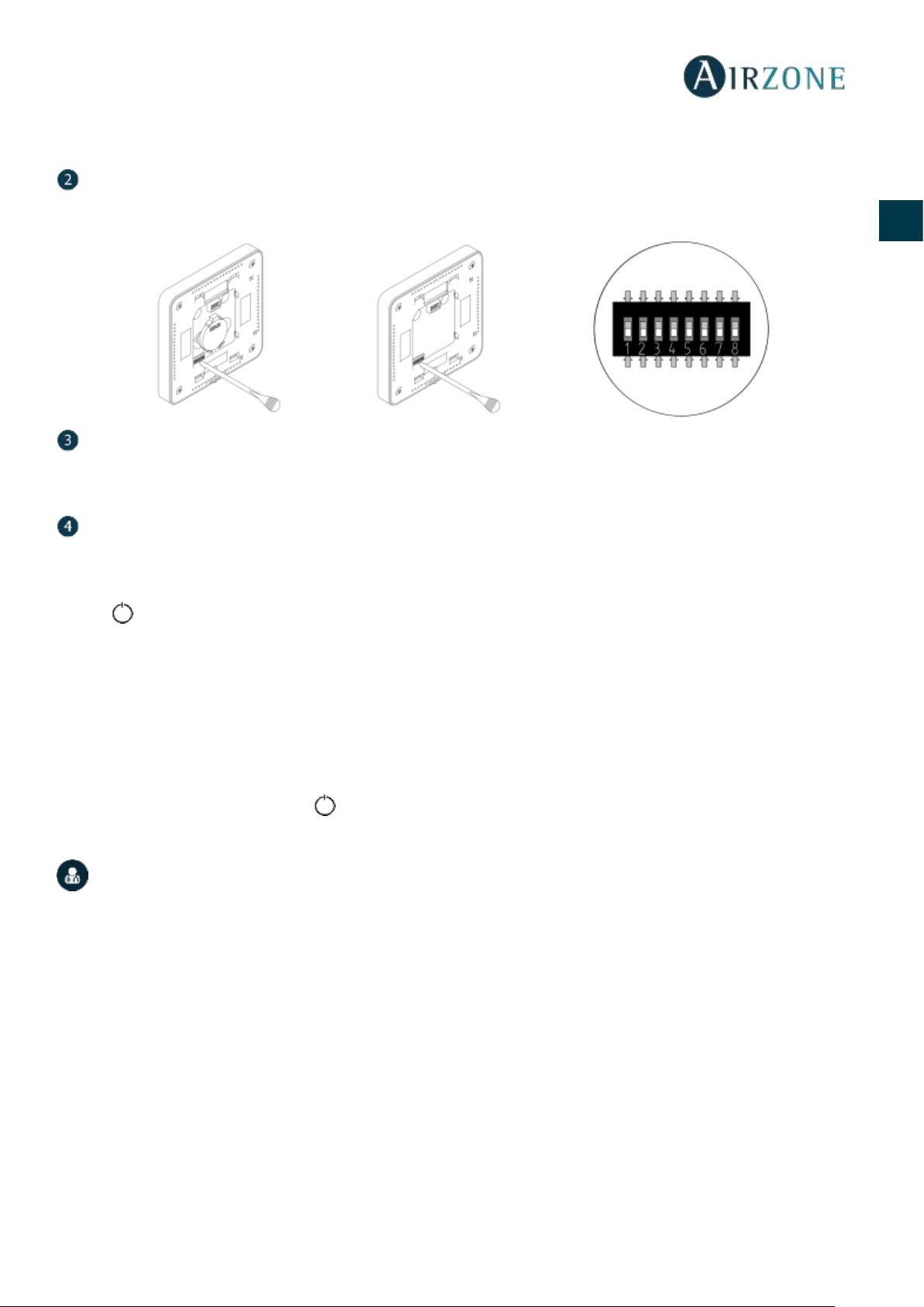
TERMOSTATO LITE
Importante: Para realizar la configuración del termostato Lite debe retirarlo de la base. Una vez configure los microswitch colóquelo
nuevamente en su base.
Canal radio (solo para termostatos radio)
Abra el canal de asociación radio. Para ello pulse sobre SW1, el LED D19 se encenderá en color rojo fijo.
Una vez abierto dispone de 15 minutos para realizar la asociación, en el caso de que se le agote el
tiempo realice de nuevo esta operación. También puede abrir el canal de asociación radio a través de
los termostatos Blueface y Think (ver apartado Parámetros de sistema)
19
ES
EN
FR
IT
PT
DE
IMPORTANTE: Recuerde no tener más de un canal abierto en la misma instalación de forma simultánea, puede ocasionar
asociaciones erróneas.
Dirección zona
Seleccione la zona asociada a este termostato subiendo el microswitch de la zona correspondiente.
Salidas asociadas
Seleccione otras salidas de control asociadas a la zona en caso de necesitarlo. La dirección de la zona será la de menor valor
seleccionado.
Otras configuraciones
Configure las demás funcionalidades del termostato Lite a través del menú de configuración avanzada de su zona desde un
termostato Blueface (ver apartado Configuración avanzada, Parámetros de zona).
El icono parpadeará 5 veces en verde para indicar que la asociación es correcta. En caso de que realice un parpadeo rojo,
indicará que la zona está ocupada y en caso de que realice 2 parpadeos rojos significará que el termostato está fuera de
cobertura.
Recuerde: En caso de necesitar cambiar el número de zona, resetee en primer lugar el termostato e inicie la secuencia de asociación.
Reset termostato Lite
En caso que quiera devolver a valores de fábrica el termostato Lite, baje todos los microswitch y coloque nuevamente el
termostato en la base. Pulse en el icono , este parpadeará dos veces en color verde confirmando la finalización del reset.
COMPROBACIÓN DE CONFIGURACIÓN INICIAL
Compruebe los siguientes ítems:
- Comunicación equipo-Sistema: Configure el sistema Airzone en un modo de funcionamiento distinto de Stop y
encienda la zona generando demanda en la misma. Verifique que el modo impuesto en el termostato maestro aparece
en el termostato de la unidad interna y que la temperatura de consigna cambia en el mismo.
- Apertura-Cierre de compuertas y salidas de control: Encienda y genere demanda en todas las zonas. A continuación,
apague y encienda cada zona para comprobar que las salidas de control asociadas son correctas.
- Compruebe que la presión estática en el equipo de conductos está acorde con las condiciones de la red de distribución
de aire donde esté instalado (consulte el manual del fabricante del equipo si necesita modificar este parámetro).
Recuerde: Por motivos de seguridad, la última zona tardará 4 minutos en cerrarse.
20
ES
EN
FR
IT
PT
DE
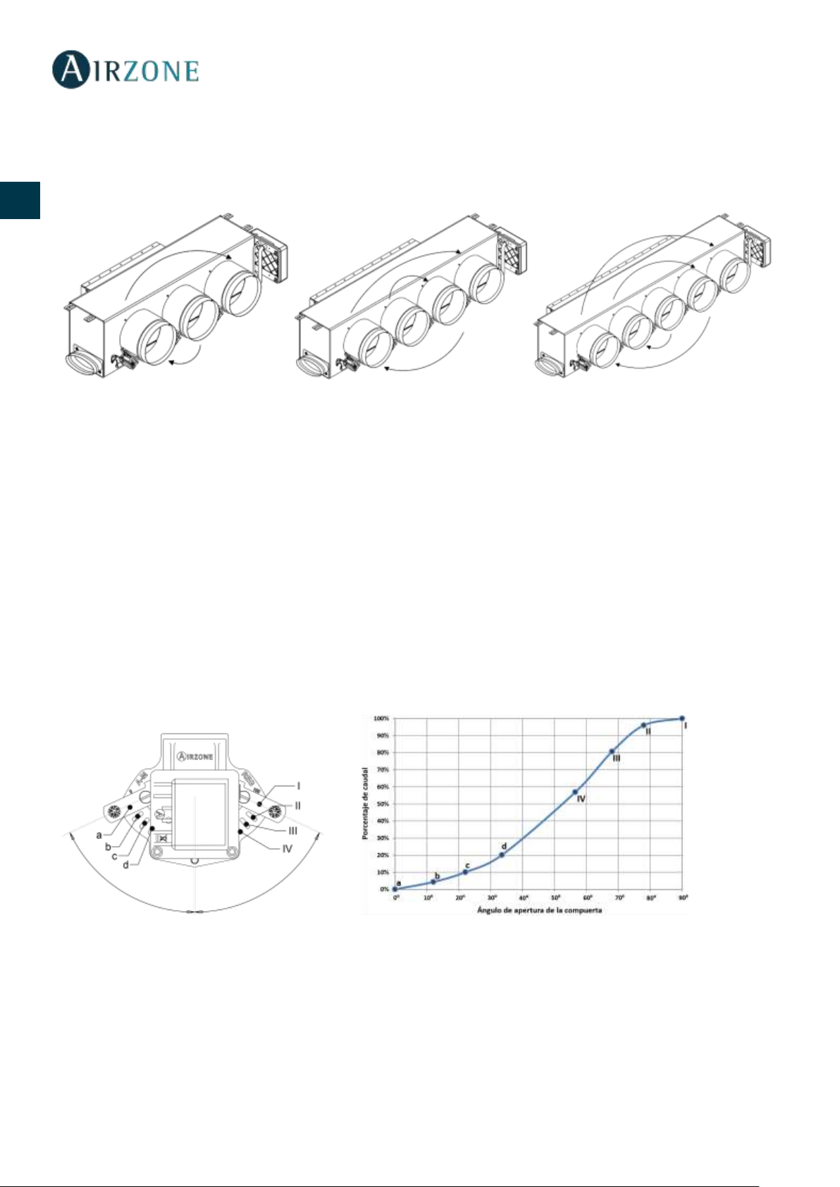
REGULACIÓN DE CAUDAL
Importante: Comience el ajuste de caudal desde las compuertas centrales hasta finalizar en la compuerta nº1.
AJUSTE DE CAUDAL (REG)
1. Encienda y genere demanda en todas las zonas para abrir todas las compuertas.
2. Apague la zona/compuerta que vaya a ajustar.
3. Ajuste la apertura máxima deseada con la palanca REG (I/II/III/IV)
4. Encienda la zona y compruebe que el caudal es correcto.
AJUSTE DE AIRE MÍNIMO (A-M)
1. Encienda y genere demanda en todas las zonas para abrir todas las compuertas.
2. Ajuste la apertura mínima deseada con la palanca A-M (a/b/c/d)
3. Apague la zona y compruebe que el caudal de aire mínimo es correcto.
A-M
REG
21
ES
EN
FR
IT
PT
DE
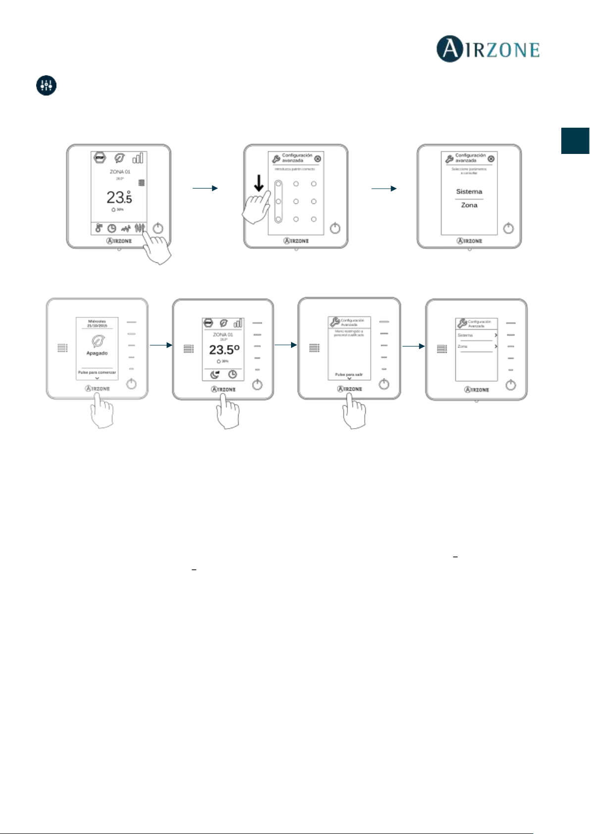
CONFIGURACIÓN AVANZADA
Para acceder al menú de configuración avanzada del Blueface y del termostato Think siga los siguientes pasos:
Blueface
Think
Dentro de este menú podrá actuar sobre parámetros de sistema y de zona.
PARÁMETROS DE SISTEMA
• Dirección de sistema. Permite definir el número del sistema en su instalación. Por defecto muestra el valor 1. El
sistema mostrará los valores de dirección libres con un valor máximo de 247.
• Rango de temperatura. Permite seleccionar la temperatura máxima para el modo calor (19 30ºC) y la temperatura
mínima para el modo frío (18 26ºC), en pasos de 1ºC. Si lo desea puede deshabilitar alguno de los modos. Por defecto
está configurado como temperatura máxima de calor 30ºC y como temperatura mínima de frío 18ºC.
• Tipo de apertura. Permite habilitar/deshabilitar la proporcionalidad de las compuertas del sistema. La
proporcionalidad gradúa en 4 pasos la apertura o cierre de la compuerta en función de la demanda de temperatura
de la zona, ajustando el caudal de la misma. Por defecto aparece configurado como Todo/Nada.
• Modo Standby (solo para termostato Blueface). Configuración de la lógica de funcionamiento de los elementos
motorizados cuando no hay demanda en el sistema. Por defecto se encuentra deshabilitado.
• Configuración relé. Permite modificar la lógica de funcionamiento del relé VMC/Caldera de la central del sistema.
(Por defecto VMC)
• Q-Adapt (solo para termostatos Think).
Permite seleccionar el algoritmo de control de caudal que mejor se adapte a su instalación de conducto. Las opciones
disponibles son:
- Máximo: el sistema trabaja a velocidad máxima, independientemente del número de zonas.
- Potencia: trabaja a una velocidad mayor que en Estándar para favorecer el aumento de caudal.
Pulsación larga
Pulsación larga
Pulsación larga
Pulsación corta

22
ES
EN
FR
IT
PT
DE
- Estándar: el sistema modifica la velocidad en función del número de zona.
- Silencio: trabaja a una velocidad menor que en Estándar para favorecer la reducción de ruido.
- Mínimo: trabaja a velocidad mínima, independientemente del número de zonas.
• Canal radio. Permite activar/desactivar el canal de asociación radio del sistema.
• Información (solo para termostatos Think). Permite visualizar información acerca de:
- La zona: Firmware, zona, asociación, motor o estado de las comunicaciones.
- El sistema: Firmware, configuración, e información de controladores de sistema e instalación.
- Los dispositivos: Indica los elementos conectados al sistema.
• Reset sistema (disponible solo para termostato Blueface maestro). Permite resetar el sistema volviendo éste a
configuración de fábrica, para volver a configurar los termostatos, diríjase al apartado Configuración inicial).
PARÁMETROS DE ZONA
• Salidas asociadas. Muestra y permite seleccionar las salidas de control asociadas al termostato.
• Conf. termostato. Permite configurar el termostato como Maestro o Zona.
*Nota: No se puede configurar como Maestro si ya existe otro termostato configurado como tal.
• Modo de uso. Permite configurar el termostato de las distintas zonas del sistema en modo Básico o Avanzado. Por
defecto está configurado como Avanzado. Los parámetros que se pueden controlar en modo Básico son:
- On/Off.
- Temperatura de consigna.
- Velocidad del ventilador.
En caso de necesitar configurar nuevamente el termostato como Avanzado acceda al menú de configuración avanzada
y habilite el modo de uso Avanzado.
• Etapas de control. Permite configurar las etapas de frío y calor en la zona seleccionada o en todas las zonas del
sistema. Las opciones a configurar son:
- Aire: Habilita calor/frío por aire en la zona seleccionada.
- Off: Deshabilita la etapa de calor/frío en la zona seleccionada.
• Offset. Permite corregir la temperatura ambiente que se mide en las distintas zonas o en todas ellas, debido a
desviaciones producidas por fuentes de calor/frío cercanas, con un factor de corrección comprendido entre - 2,5ºC y
2,5ºC en pasos de 0,5ºC. Por defecto se encuentra configurado en 0ºC.
• Reset termostato (no disponible en zonas remotas). Permite resetar el termostato volviendo este al menú de
configuración inicial (ver apartado Configuración inicial termostatos Blueface y Think).
23
ES
EN
FR
IT
PT
DE
AUTODIAGNÓSTICO
CENTRAL DE SISTEMA INNOBUS PRO6 (AZCE6IBPRO6)
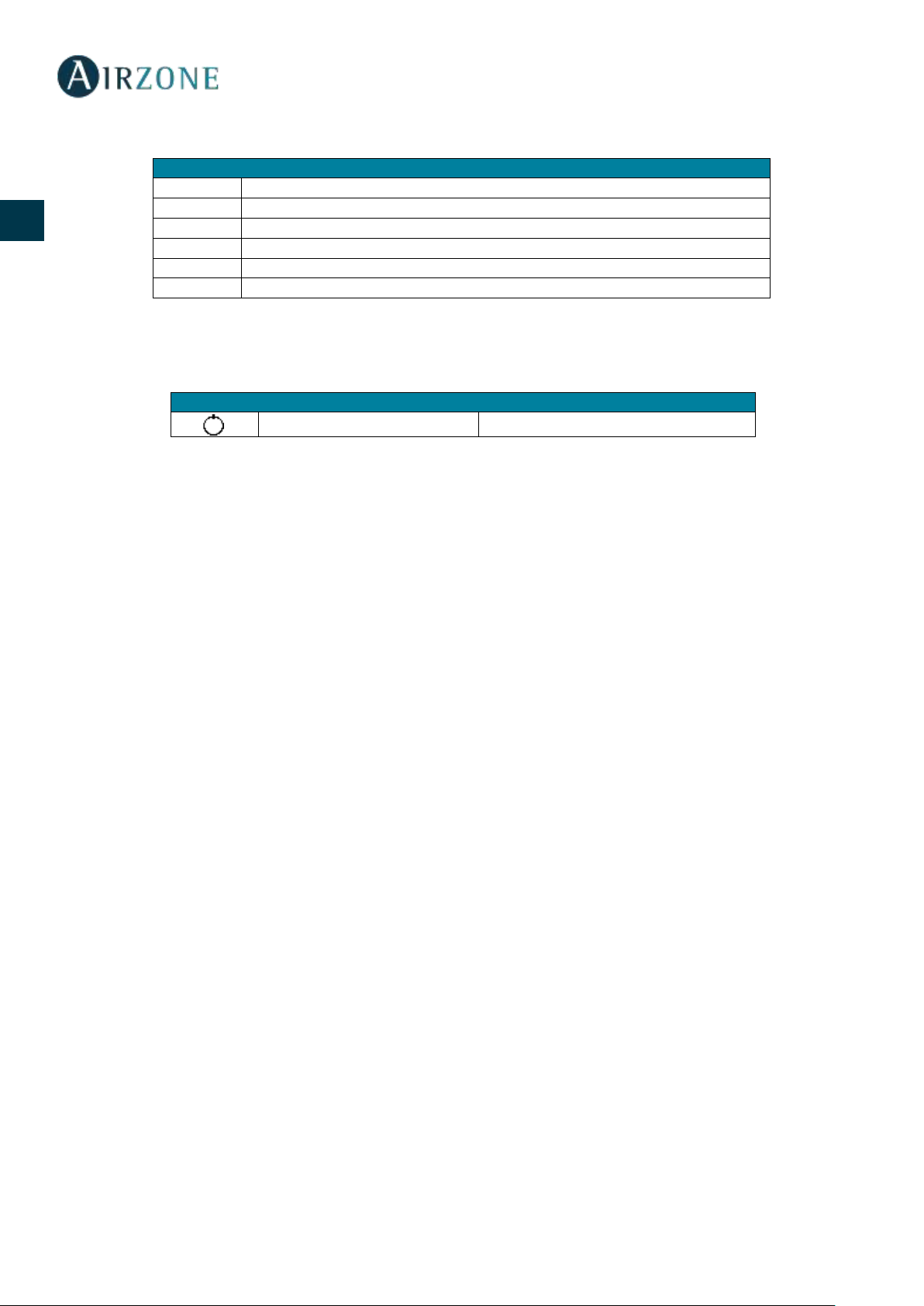
PASARELA DE COMUNICACIÓN DAIKIN (AZX6GTCDA1)
Significado
D1
Recepción de datos del bus domótico
Parpadeo
Verde
D2
Transmisión de datos del bus domótico
Parpadeo
Rojo
D3
Actividad de la central
Parpadeo
Verde
D4
Transmisión de datos del bus de conexión Airzone
Parpadeo
Rojo
D5
Recepción de datos del bus de conexión Airzone
Parpadeo
Verde
D6
On/Off máquina
Parpadeo
Verde
D7
VMC-Caldera
Parpadeo
Verde
D10
Recepción de paquetes vía radio
Conmuta
Verde
D11
Alimentación de la central
Fijo
Rojo
D18
Elemento asociado
Fijo
Verde
D19
Canal asociación activo
Fijo
Rojo
Apertura motorizaciones
Encendido
Verde
Cierre motorizaciones
Encendido
Rojo
Significado
D3
Actividad del micro controlador
Parpadeo
Verde
D8
Transmisión de datos hacia el sistema Airzone
Parpadeo
Rojo
D9
Recepción de datos desde el sistema Airzone
Parpadeo
Verde
D11
Alimentación de la pasarela
Fijo
Rojo
D34
Transmisión de datos hacia la unidad interior
Parpadeo
Rojo
D35
Recepción de datos desde la unidad interior
Parpadeo
Verde
24
ES
EN
FR
IT
PT
DE
TERMOSTATOS BLUEFACE Y THINK (AZCE6BLUEFACEC / AZCE6THINKR)
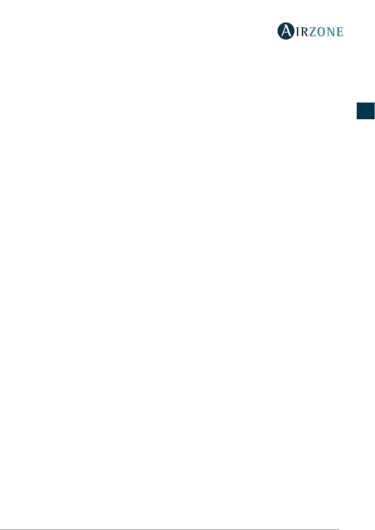
TERMOSTATO LITE RADIO (AZCE6LITER)
Significado
Error 1
Error de comunicaciones con la central
Error 5
Sonda de temperatura en circuito abierto
Error 6
Sonda de temperatura en cortocircuito
Error 8
Termostato Lite no encontrado
Error 9
Error de comunicaciones pasarela-sistema
Error 11
Error comunicaciones pasarela-máquina
Significado
Parpadeo rápido rojo
Error de comunicaciones con la central
25
ES
EN
FR
IT
PT
DE
CONTENTS
Warnings and environmental policy ................................................................................................................................................................................................... 26
Precautions ............................................................................................................................................................................................................................................ 26
Environmental policy .......................................................................................................................................................................................................................... 26
General requirements .............................................................................................................................................................................................................................. 27
System elements ....................................................................................................................................................................................................................................... 28
Innobus Pro6 main control board (AZCE6IBPRO6) .................................................................................................................................................................... 28
Technical specs .............................................................................................................................................................................................................................. 28
Daikin communication gateway (AZX6GTCDA1) ...................................................................................................................................................................... 29
Technical specs .............................................................................................................................................................................................................................. 29
Blueface intelligent thermostat (AZCE6BLUEFACEC) ............................................................................................................................................................... 29
Technical specs .............................................................................................................................................................................................................................. 30
Wireless Think thermostat (AZCE6THINKR) ................................................................................................................................................................................. 30
Technical specs .............................................................................................................................................................................................................................. 30
Wireless Lite thermostat (AZCE6LITER) ......................................................................................................................................................................................... 31
Technical specs .............................................................................................................................................................................................................................. 31
Standard motorized plenum (AZEZ6DAIST) ................................................................................................................................................................................ 31
Low profile motorized plenum (AZEZ6DAISL) ............................................................................................................................................................................ 32
System installation..................................................................................................................................................................................................................................... 32
System assembly ....................................................................................................................................................................................................................................... 33
Easyzone assembly .............................................................................................................................................................................................................................. 33
Assembly to indoor unit .................................................................................................................................................................................................................... 33
Bypass damper assembly .................................................................................................................................................................................................................. 34
Ventilation air inlet assembly ........................................................................................................................................................................................................... 34
How to change the actuator............................................................................................................................................................................................................. 35
Thermostat assembly (AZCE6BLUEFACEC / AZCE6THINKR / AZCE6LITER) ........................................................................................................................ 36
Indoor unit connection ........................................................................................................................................................................................................................... 36
System assembly ....................................................................................................................................................................................................................................... 37
Innobus Pro6 main control board (AZCE6IBPRO6) .................................................................................................................................................................... 37
Reset the system ............................................................................................................................................................................................................................ 38
Changing batteries ....................................................................................................................................................................................................................... 38
Assembly and connection evaluation .......................................................................................................................................................................................... 38
Initial configuration .................................................................................................................................................................................................................................. 38
Blueface and Think thermostats ...................................................................................................................................................................................................... 38
Lite thermostat ..................................................................................................................................................................................................................................... 40
Lite thermostat reset .................................................................................................................................................................................................................... 41
Initial Configuration evaluation...................................................................................................................................................................................................... 41
Flow regulation ........................................................................................................................................................................................................................................... 42
Flow adjustment (REG) ....................................................................................................................................................................................................................... 42
Minimum air setting (A-M) ................................................................................................................................................................................................................ 42
Advanced settings .................................................................................................................................................................................................................................... 43
System parameters .............................................................................................................................................................................................................................. 43
Zone Parameters .................................................................................................................................................................................................................................. 44
Self-diagnose ............................................................................................................................................................................................................................................... 45
Innobus Pro6 main control board (AZCE6IBPRO6) .................................................................................................................................................................... 45
Daikin communication gateway (AZX6GTCDA1) ...................................................................................................................................................................... 45
Blueface and Think thermostat (AZCE6BLUEFACEC / AZCE6THINKR) ................................................................................................................................. 46
Wireless Lite thermostat (AZCE6LITER) ......................................................................................................................................................................................... 46
26
ES
EN
FR
IT
PT
DE
WARNINGS AND ENVIRONMENTAL POLICY
PRECAUTIONS
For your security, and to protect the devices, follow these instructions:
• Do not handle the system with wet or damp hands.
• Disconnect the power supply before making any connections.
• Take care not to cause a short circuit in any of the system connections.
ENVIRONMENTAL POLICY
Do not dispose of this equipment in the household waste. Electrical and electronic
equipment contain substances that may damage the environment if they are not handled
appropriately. The symbol of a crossed-out waste bin indicates that electrical equipment
should be collected separately from other urban waste. For correct environmental
management, it must be taken to the collection centres provided for this purpose, at the end
of its useful life.
on environmental protection.
If you replace it with other equipment, you must return it to the distributor or take it to a
specialized collection center.
Those breaking the law or by-laws will be subject to such fines and measures as are laid down
in environmental protection legislation.
Access all our technical documents and the self-diagnosis section, check the most FAQs, certificates
and watch our videos at: myzone.airzone.es/products/
Access our declaration of conformity at:
http://doc.airzone.es/producto/Gama_AZ6/Airzone/Certificados/Declarat
ion_of_conformity_AZ6.pdf
Hereby, Corporación Empresarial Altra, S.L., declares that the AZEZ6DAIxxxxxxx is in compliance with the essential
requirements and other relevant provisions of directive 2014/53/EU.
27
ES
EN
FR
IT
PT
DE
GENERAL REQUIREMENTS
Strictly follow the directions outlined in this manual:
• This system must be installed by a qualified technician.
• Verify that the units to be controlled have been installed according to the manufacturer's requirements and operate
correctly before installing the Airzone System.
• Locate and connect all the devices of the installation in accordance with the electronic regulations in force.
• Verify that the air conditioning installation to be controlled is in accordance with the regulations in force.
• It is necessary to use a Blueface Thermostat to have all the features of the Airzone system.
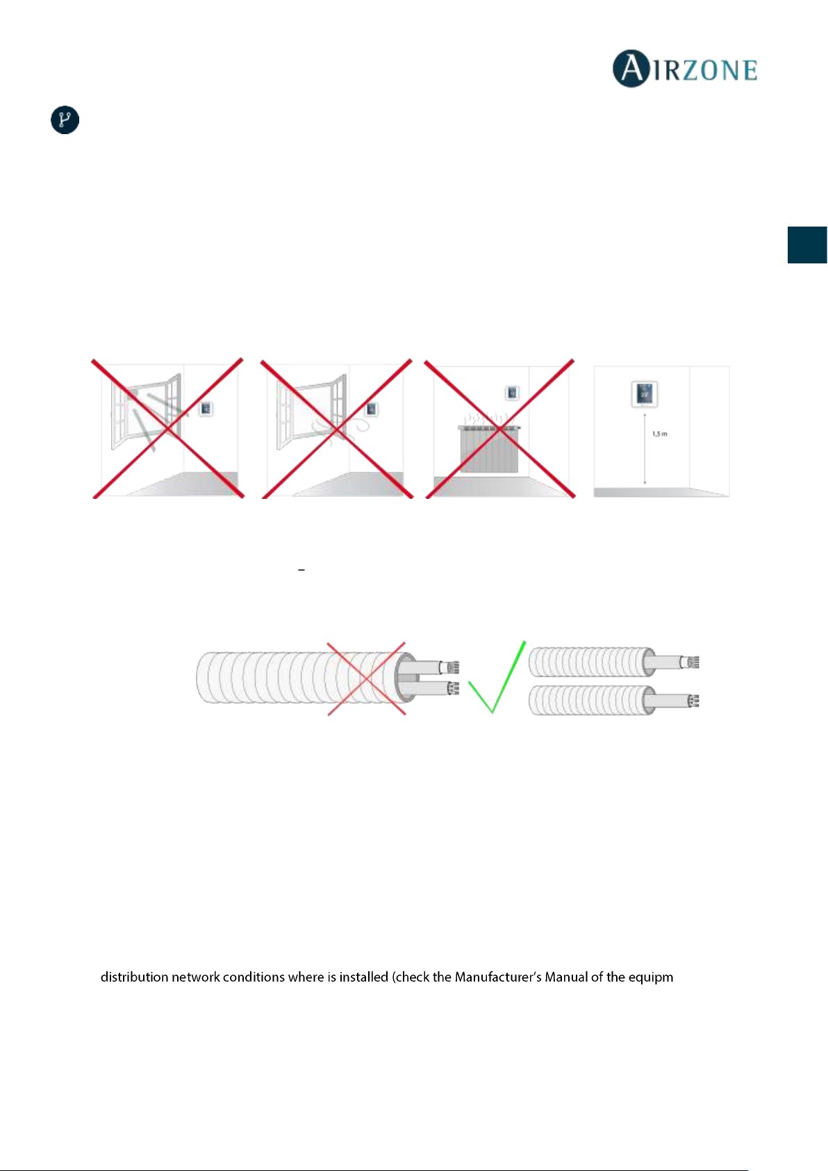
• Follow these recommendations to locate the thermostats:
• Perform all the connections with total abscense of power suppliance.
• In order to connect the elements of the system, use a proper cable cable: shielded twisted pair cable formed by 4 wires:
2x0,22 mm2 + 2x0,5mm2 (AWG 20 4 wired).
• Do not place the system bus close to lines of force, fluorescent lights, LED lamps, motors, etc. It might cause
interference on the communications.
• Respect the connection polarity of each device. A wrong connection may seriously damage the product.
• For elements externally powered at 110 /230 Vac, for the communications, it is only necessary to connect the poles "A"
and "B" of the bus.
• For elements externally powered at 110/230 Vac, respect the connection polarity. A wrong grounding may produce
electric shocks.
• According to the current local and national regulations, it is mandatory to add a switch (or other element to disconnect
the system) to the external supply wiring so that a constant separation between poles is guaranteed. The system will
restart automatically if the supply is eventually turned off. Use an independent circuit from the controlled system
for the power supply.
• Once the Airzone system is configured, verify that the static pressure of the duct system complies with the air
ent if you need to
modify this parameter).
28
ES
EN
FR
IT
PT
DE
SYSTEM ELEMENTS
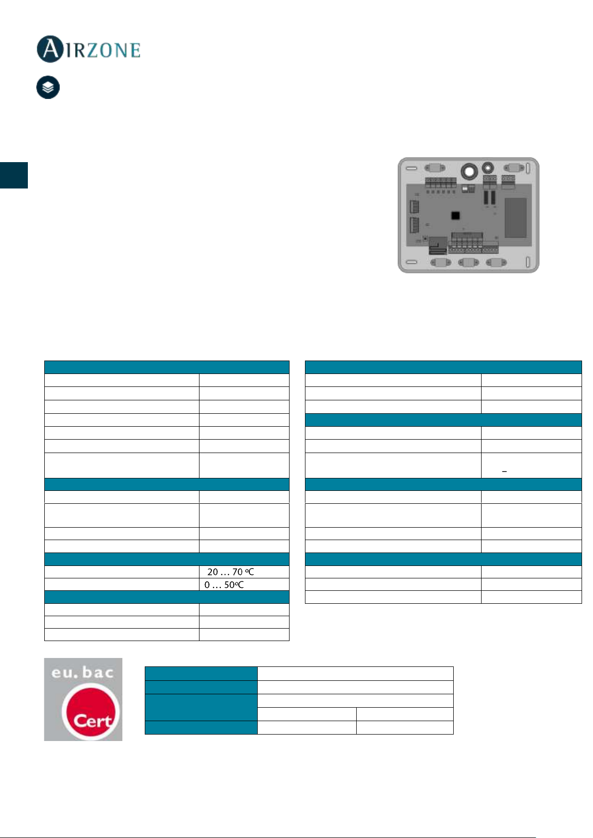
INNOBUS PRO6 MAIN CONTROL BOARD (AZCE6IBPRO6)
Electronic board that controls the system through wired and wireless devices. Wall mounted.
Functionalities:
• Control and management of the thermostats (up to 6 zones).
• Power outlets for motorized elements.
• Remote zone on/off module (up to 6 zones).
• Relay outlet configurable as CMV (Controlled Mechanical Ventilation) or
boiler.
• Control gateway management.
• Communication with units of integral control of the installation.
• Communications with other external control systems through integration bus.
Technical specs
Power supply and consumption
Airzone connection bus
Type of power supply
Vac
Nº of ports
3
V max
110 / 230 V
Shielded twisted pair
2 x 0,22 + 2x0,5 mm2
I max
250 mA
V max
12 V
Frequency
60/50 Hz
Automation bus
Stand-by consumption
400 mW
Nº of ports
1
Maximum consumption
25 W
Shielded twisted pair
2 x 0,22 + 2x0,5 mm2
Module over-current protection
250 mA
Communications protocol
MODBUS RS-485
Par 19200 bps
Communications via radio
Actuator outputs
Communications protocol
Airzone
Nº of outputs
6
Frequency
868 MHz
Maximum number of outputs per
damper
2
Radiation power
5 dBm
Vmax
± 12 V
Maximum distance in open space
40 m
Imax
150 mA
Operating temperatures
Relay outputs
Storage
-
Nº of relays
2
Operation V max
24 / 48 V
Mechanical aspects
I max
I max
Protection class
IP 20
Weight
616 g
Dimensions (WxHxD)
195x180x55,5 mm
Type
Airzone Central V1.3
Licence
215562
Application
Variable air volume system (without h/c coil)
Heating
Cooling
Control accuracy (K)
0.3
0.3
29
ES
EN
FR
IT
PT
DE
DAIKIN COMMUNICATION GATEWAY (AZX6GTCDA1)
Gateway for the management of Daikin AC units compatible with Airzone control systems. Powered
by the indoor unit. Assembly and connection on the AC unit bus of the enabled Airzone devices.
Product developed and tested in collaboration with the manufacturer.
Features:
• Two-way communication of the basic control parameters depending on the demand of the
Airzone control system.
• Automatic control of up to 5 speeds, enabling (generally) the operating without bypass.
• Adjustment of the set point temperature based on the selected temperatures in the Airzone
thermostats and the Eco-Adapt algorithm.
• Reading of the operating temperature of the system.
• Reading of warnings and errors of the controlled unit.
• Master control of the unit.
Technical specs
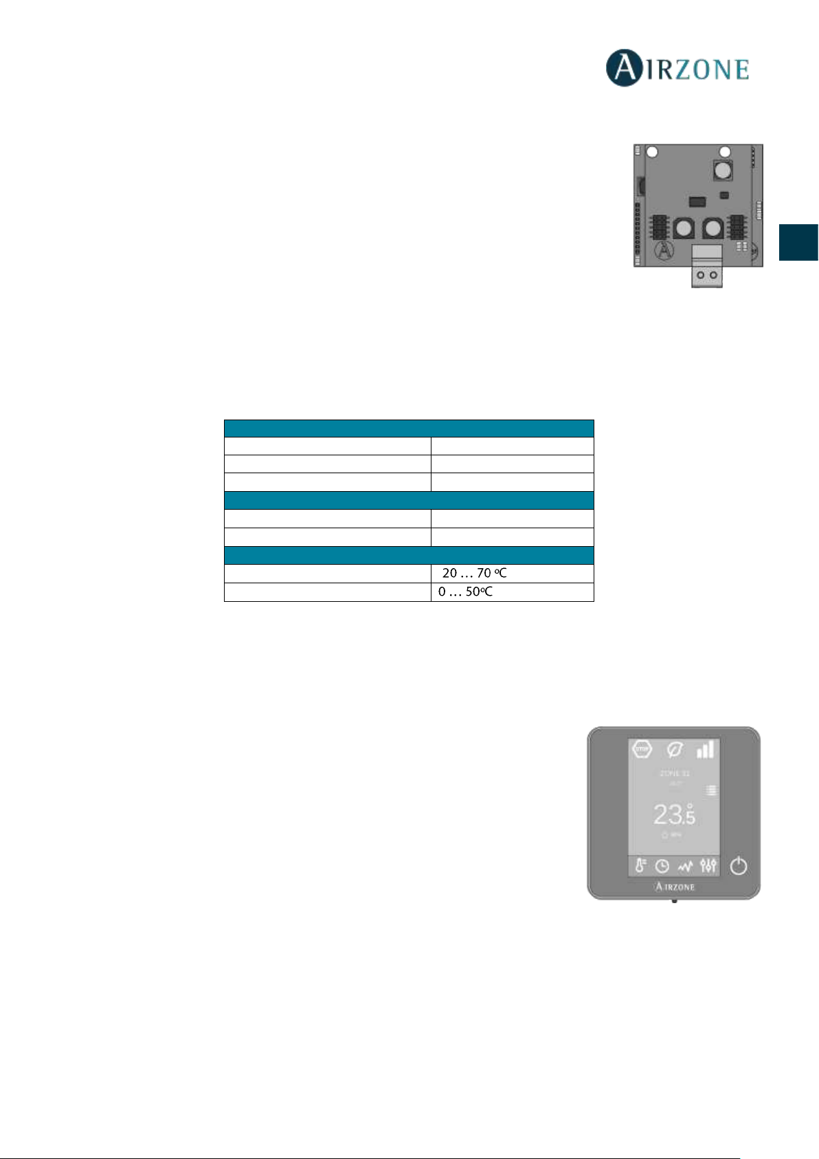
BLUEFACE INTELLIGENT THERMOSTAT (AZCE6BLUEFACEC)
Colour graphic interface with capacitive screen for controlling zones in Airzone systems. Powered by main control board.
Finished in steel and glass. Available in white or black.
Functionalities:
• Available in Spanish, English, French, Italian, German and Portuguese.
• Control of temperature, operating mode (Master thermostat) and system speed
(Master thermostat and fancoil installations).
• Room temperature and relative humidity measurement of the zone.
• Eco-Adapt saving and Sleep function.
• Temperature and mode time schedules.
• Remote access to other zones of the system.
Power supply and consumption
Power supply
Indoor unit
V max
16 Vdc
I max
25 mA
Communications
Type of cable
Shielded twisted pair
Communication wires
2 x 0,75 mm2
Operating temperatures
Storage
-
Operation
30
ES
EN
FR
IT
PT
DE
Technical specs
WIRELESS THINK THERMOSTAT (AZCE6THINKR)
Graphic interface with low-energy e-ink screen and capacitive buttons for controlling zones
in Airzone systems. Wireless communications. Powered by battery button CR2450. Finished
in steel and glass. Available in white or black.
Functionalities:
• Available in Spanish, English, French, Italian, German and Portuguese.
• Control of temperature, operating mode (Master thermostat) and system speed
(Master thermostat and in fancoil installations).
• Room temperature and relative humidity reading.
• Sleep function.
Technical specs
Power supply and consumption
Operating temperatures
Type of power supply
Vdc
Storage
-
V max
12 V
Operation
I max
145 mA
Set-point temperature range
Stand-by consumption
0,876 W
Reading accuracy
±0,1 ºC
Maximum consumption
1,74 W
Display accuracy
±0,1 ºC
Connection and communications
Relative humidity
±4 %
Type of cable
Shielded twisted pair
Mechanical aspects
Communication wires
2 x 0,22 mm2
Assembly
Surface through support
Power supply wires
2 x 0,5 mm2
Protection class
IP 20
Maximum distance
40 m
Type of probe
Airzone_NTC_10K
Weight
198 g
Dimensions (WxHxD)
92x 92x15,85 mm
Power supply and consumption
Operating temperatures
Type of power supply
Vdc
Storage
-
V max
3,3 V
Operation
I max
30 mA
Set-point temperature range
Battery
CR2450
Reading accuracy
±0,1 ºC
Useful life of battery
2 years
Display accuracy
±0,1 ºC
Stand-by consumption
0,01 mW
Relative humidity
±4 %
Maximum consumption
100 mW
Mechanical aspects
Connection and communications
Assembly
Surface through support
Communication frequency
868 MHz
Protection class
IP 20
Maximum power
0 dBm
Type of probe
Airzone_NTC_10K
Maximum distance in open space
40 m
Weight
180 g
Dimensions (WxHxD)
92x 92x15,85 mm

31
ES
EN
FR
IT
PT
DE
WIRELESS LITE THERMOSTAT (AZCE6LITER)
Thermostat with capacitive buttons for controlling the temperature of the zones in Airzone
systems. Finished in steel and glass. Wireless communications. Powered by CR2450 button
battery. Available in white and black.
Functionalities:
• On/off of the zone.
• Set-point temperature control (Accuracy: ± 1ºC, up to a limit of ±3ºC.)
• Room temperature and relative humidity reading.
Technical specs
STANDARD MOTORIZED PLENUM (AZEZ6DAIST)
Airzone standard motorized plenum includes:
- Main board.
- Communication gateway
- Circular dampers of 200 mm in diameter.
- Manual control system of flow.
- Controlled mechanical ventilation (CMV) input of
150 mm in diameter.
Variations of up to ±3 dB(A) over the sound pressure of
the indoor unit. Maximum weight = 18 kg.
Size
XS S M L XL
No. of dampers
Size in mm (L x H x W)
2 / 3
930 x 300 x 454
930 x 300 x 454
4
1140 x 300 x 454
1140 x 300 x 454
5
1425 x 300 x 454
1425 x 300 x 454
1425 x 300 x 454
6
1638 x 300 x 454
1638 x 300 x 454
7 / 8
1425 x 515 x 454
1425 x 515 x 454
Plenum code: AZEZ6DAIST07 [Size] [No. of dampers]
Power supply and consumption
Operating temperatures
Type of power supply
Vdc
Storage
-
V max
3,3 V
Operation
I max
30 mA
Set-point temperature range
Battery
CR2450
Reading accuracy
±0,1 ºC
Useful life of battery
2 years
Display accuracy
±0,1 ºC
Stand-by consumption
0,01 mW
Relative humidity
±4 %
Maximum consumption
100 mW
Mechanical aspects
Connection and communications
Assembly
Surface through support
Communication frequency
868 MHz
Protection class
IP 20
Maximum power
0 dBm
Type of probe
Airzone_NTC_10K
Maximum distance in open space
40 m
Weight
184 g
Dimensions (WxHxD)
92x 92x15,85 mm

32
ES
EN
FR
IT
PT
DE
LOW PROFILE MOTORIZED PLENUM (AZEZ6DAISL)
Airzone low profile motorized plenum includes:
- Main board.
- Communication gateway.
- Circular dampers of 150 mm in diameter.
- Manual control system of flow.
- Controlled mechanical ventilation (CMV) input of
150 mm in diameter.
Variations of up to ±3 dB(A) over the sound pressure of
the indoor unit. Maximum weight = 18 kg.
Size S M
L
No. of dampers
Size in mm (L x H x W)
2 / 3
720 x 210 x 444
4
930 x 210 x 444
5
1140 x 210 x 444
Plenum code: AZEZ6DAISL01 [Size] [No. of dampers]
SYSTEM INSTALLATION
In order to install the system, carefully follow these steps:
Connect all the necessary elements (see section System assembly)
- Connect the communication gateway whit the AC indoor unit to controller.
- Connect all the elements of the system (thermostats, modules, etc.).
- Power the main board.
Check all the assembly and the connection are correct (see section Assembly and connection evaluation)
Configure the system
- Configure all the thermostats (see sections Initial configuration and Advanced settings).
- Remember that Airzone system allow you to configure master and zone thermostats (Master thermostats let you
change operating modes, select the efficiency degree with the Eco-Adapt function or select the speed of the system).
If you have any other doubt, check the user and installation manuals
It does not require any maintenance

33
ES
EN
FR
IT
PT
DE
SYSTEM ASSEMBLY
EASYZONE ASSEMBLY
Important: It is recommended to insulate all the metal parts of Easyzone that are exposed to outdoor conditions in order to
prevent condensation.
Remember: The motorized elements are numbered the following way:
ASSEMBLY TO INDOOR UNIT
Place the Easyzone in the pressure port of the unit and attach it to this using the screws.
After fixing screws be sure to insulate the connection frame to prevent condensation forming. Use bands of insulating
material (glass wool or polyethylene foam) of a thickness of 25 mm. The width of the insulation bands are 97 mm for standard
motorized plenum and 36 mm for low profile motorized plenum.
Attach the Easyzone to the ceiling through the tabs on the ends with threaded rods.

34
ES
EN
FR
IT
PT
DE
BYPASS DAMPER ASSEMBLY
Sharply hit it to take away the pre-cut area of the sides corresponding to the bypass.
Use a sharp blade to remove the insulation that covers the area of the bypass and uncover the mounting slots on the
bypass.
Fit the bypass damper in the slots and rotate it clockwise until the stop.
Attach the bypass damper to the plenum using a sheet metal screw (Ø: 3.9 mm).
VENTILATION AIR INLET ASSEMBLY
Remove the elliptical neck that is secured by screws.
Remove the protection plate that covers the external air intake and reattach the elliptical neck.
Double or cut the lid at the bottom of the pressure dampers to allow the air to pass.

35
ES
EN
FR
IT
PT
DE
HOW TO CHANGE THE ACTUATOR
Disconnect the actuator.
Loosen the fixing screw using an Allen key (number 3) and remove the actuator from the damper.
Fix the new actuator to fit in the bolt.
Turn the actuator until it fits in the second bolt to guarantee the proper position of the damper.
Insert and screw the fixing screw.
Connect the cable.

36
ES
EN
FR
IT
PT
DE
THERMOSTAT ASSEMBLY (AZCE6BLUEFACEC / AZCE6THINKR / AZCE6LITER)
Airzone thermostats are mounted on the wall through a support. It is recommended not to locate it more than 40 meters away
from the main control board. To fix it to the wall, follow these steps:
• Separate the back part of the thermostat from the wall support and make all the
connections (AZCE6BLUEFACEC) or insert the CR2450 button battery
(AZCE6THINKR and AZCE6LITER).
• Fix the back part of the thermostat to the wall.
• Place the display on the support once it is fixed.
• Place the anti-theft rods for additional support (optional).
INDOOR UNIT CONNECTION
1) Disconnect the power supply of the Daikin indoor unit and the Airzone system.
2) Find the P1 P2 connection of the Daikin indoor unit (where the thermostat is connected).
3) Connect the Airzone Gateway to the P1 P2 port of the Daikin unit using the cable supplied by Airzone.
4) Power the Daikin indoor unit and the Airzone system. Check the gateway LEDs (see self-diagnosis section).
5)
Service Settings > Field Settings > 1e-2-01. If you have any doubt, please check the Instruction manual Daikin
BRC1E52A7.
P1 Red
P2 - Black

37
ES
EN
FR
IT
PT
DE
SYSTEM ASSEMBLY
INNOBUS PRO6 MAIN CONTROL BOARD (AZCE6IBPRO6)
1.- Airzone thermostats
If using a wired thermostat, connect it in one of the 3 Airzone connection bus terminals. The
connection can be both a Bus connection or a star connection. Use (2x0.5+2x0.22 mm2)
Airzone wire. For added security, secure the wires using the turrets.
In case of wireless element, check it has the battery on.
2.- Powering the system
Use the power input to power at 110 / 230 Vac the main control board and any others control
elements that require it. Use the appropriate cable (3x1.5 mm²). To power supply the Main Board of
the system, loosen the cable gland if necessary and insert the cable through the hole (Ø: 5-10 mm),
attach the cables with the terminal following the indicated polarity. Connect the terminal to the power
supply input and tighten the cable gland to attach the power supply cable.
No.
Description
Airzone connection bus
Wireless module
SW1
Domotic bus
Daikin gateway
Actuator outputs
Alarm input (normally closed)
Temperature probe
CMV/Boiler
AC Start-stop relay
Power supply
On/off module
Important: Use a shielded twisted cable to control the
inputs of the on/off module.
Thermostat
Press

38
ES
EN
FR
IT
PT
DE
According to the current local and national regulations, it is mandatory to add a switch (or other element
to disconnect the system) to the external supply wiring so that a constant separation between poles is
guaranteed. The system will restart automatically if the supply is eventually turned off. Use an
independent circuit from the controlled system for the power supply.
Remember: Once all the connections are made, make sure you replace the cover properly.
Reset the system
If you want to return to factory values, press and hold SW1 until LED D19 stops flashing. Wait for the
LEDS to go back to their normal state before starting with the initial configuration process.
Changing batteries
To replace the battery, separate the thermostat from its support and
replace the battery (CR2450).
Important: We recommend using of top-brand batteries. Using lowquality batteries may reduce the duration of use.
Remember to deposit the old battery into an appropriate recycling point.
Note: Do not forget to remove the security system before taking away the
thermostat from the wall.
ASSEMBLY AND CONNECTION EVALUATION
Check the following aspects:
- The state of the LEDs of the main control board and the rest of control elements. Check the self-diagnose section.
- Wired and wireless thermostats power supply.
INITIAL CONFIGURATION
BLUEFACE AND THINK THERMOSTATS
Important: Once you start the process, it cannot be interrupted.
Language/Country
Select your language and country. These are the available languages: Spanish, English, French, Italian, German and Portuguese.
To associate a wireless Think thermostat, start the radio channel search:

39
ES
EN
FR
IT
PT
DE
Setting wireless device
- Open the radio channel. To do that, press on SW1. The LED D19 will remain solid red. Once
open, you have 15 minutes to make the association. If that period of time expires, start the
process over again. Remember not to open more than one module at the same time, it may
alter the process. You can also open the channel association radio through the Blueface and
Think (see section System parameters).
IMPORTANT: not to open more than one radio channel at the same time, it may alter the
process.
- Start the radio channel search, to do so, press Airzone to start the search.
- Verify the range is correct (30% minimum) and confirm.
Zone address
Select the zone associated to the thermostat. All the zones have a corresponding control output. For example, the zone 1 will
control the actuator output 1.
Associated outputs
If necessary, the system allows you to associate more than one control output to a zone. It is possible to control multiple outputs
from the same thermostat.
Thermostat configuration
Select the operation of the thermostat:
- Master: Controls all the parameters of the installation.
- Zone: Controls all the parameters of the zone.
Other settings
Access the advanced settings menu (system address, stages of control, etc.) to change any other setting. Activate the basic
function if required (see Advanced Settings, zone parameters).
Blueface

40
ES
EN
FR
IT
PT
DE
Think
Important: Use to confirm a nd to return.
LITE THERMOSTAT
Important: To configure a Lite thermostat you must move it away from its base. Once the microswitches are configured, put it back
in its original position.
Setting wireless device (only available for wireless thermostat)
- Open the radio channel. To do that, press on SW1. The LED D19 will remain solid red. Once
open, you have 15 minutes to make the association. If that period of time expires, start the
process over again. Remember not to open more than one module at the same time, it may
alter the process. You can also open the channel association radio through the Blueface and
Think (see section System parameters).

41
ES
EN
FR
IT
PT
DE
IMPORTANT: not to open more than one radio channel at the same time, it may alter the process.
Zone address
Select the zone associated to the thermostat pulling up the microswitch of the corresponding zone.
Associated outputs
If required, select other control outputs associated to the zone. The address zone will be the one with a lower value.
Other settings
Configure other functionalities of the Lite thermostat from the advanced configuration menu of a Blueface thermostat (see
section Advanced Settings, Zone parameters).
If the association is correct, the icon will flash green 5 times. If it flashes red, it means the zone is already occupied. If it
flashes red twice, it means the thermostat is out of range.
Remember: If you need to change the zone number, reset the thermostat and start association process.
Lite thermostat reset
If you want to return your Lite thermostat to factory values, pull down all the microswitchs and reinsert the thermostat in its
base. Press on , the icon will flash green twice when the reset process is completed.
INITIAL CONFIGURATION EVALUATION
Check the following aspects:
- AC unit-system communication: Choose any mode (except STOP mode) and switch on the zone to generate demand.
Verify that the selected operation mode in the Master thermostat is shown in the indoor unit thermostat and the setpoint temperature changes.
- Opening-closing of the dampers and control outputs: Turn on the system and generate demand in all the zones. Then,
switch off and on all the zones to verify the associated control outputs are correct.
- Verify that the static pressure of the duct system complies with the air distribution network conditions where is
Important: For security reasons, the last zone will take around 4 minutes to close.

42
ES
EN
FR
IT
PT
DE
FLOW REGULATION
Important: Start adjusting the flow from the central dampers and finish off with damper 1.
FLOW ADJUSTMENT (REG)
1. Turn on and generate demand in all zones to open all the dampers.
2. Turn off the zone/damper to be adjusted.
3. Adjust the maximum opening you want with the REG lever (I/II/III/IV)
4. Turn on the zone and check the flow is correct.
MINIMUM AIR SETTING (A-M)
5. Turn on and generate demand in all zones to open all the dampers.
6. Adjust the minimum opening you want with the M-A lever (a/b/c/d)
7. Turn on the zone and check the minimum air flow is correct.
A-M
REG
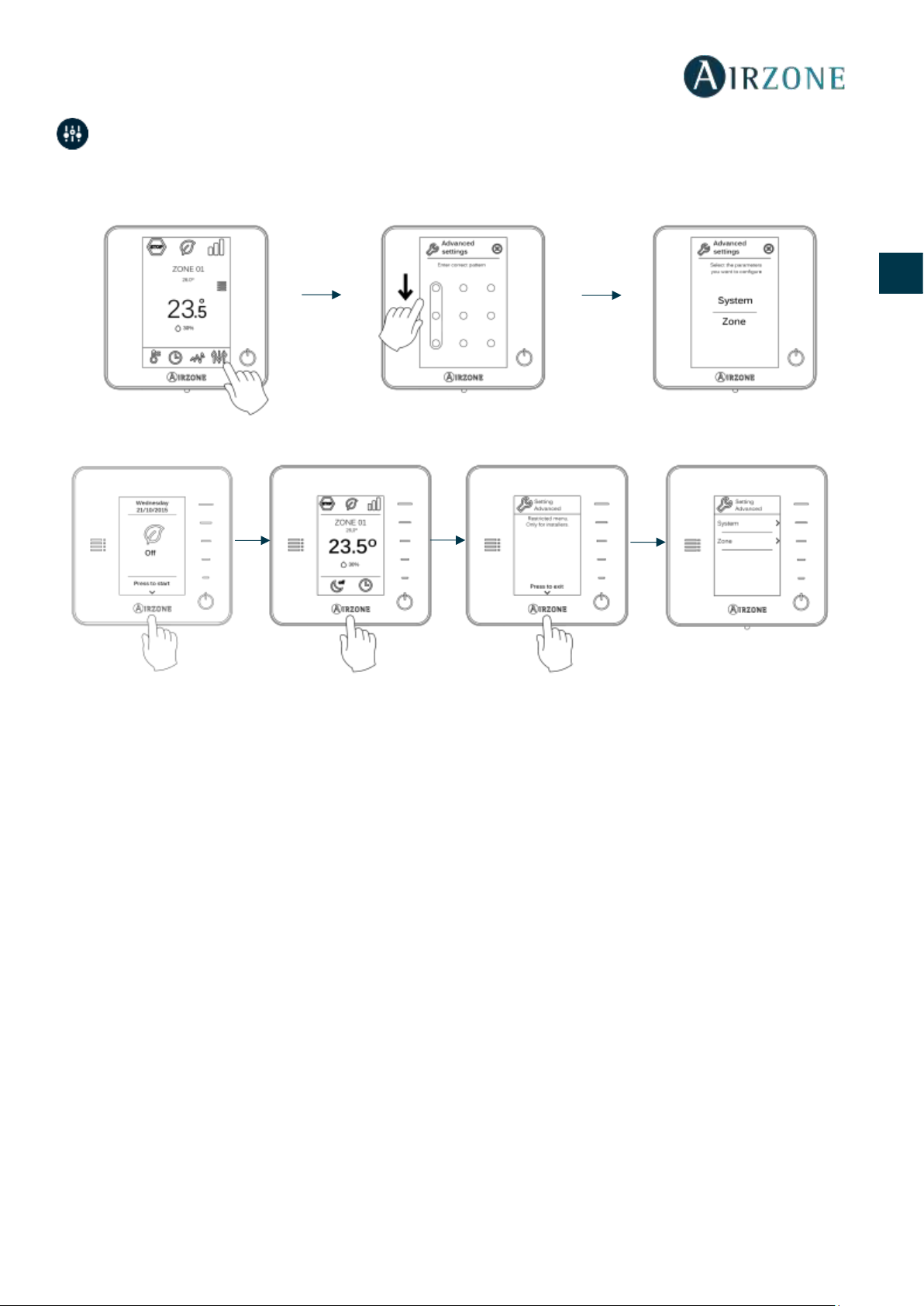
43
ES
EN
FR
IT
PT
DE
ADVANCED SETTINGS
To access the advanced configuration menu of the thermostat and Blueface Think follow the following steps:
Blueface
Think
From this menu you can change the system and zone parameters.
SYSTEM PARAMETERS
• System address. Defines the number of the system within your installation. The value 1 is shown by default. The
system will display the available values (max = 247).
• Temperature range. Selects the highest temperature in heating mode (19-30 ºC) and the lowest temperature in
cooling mode (18-26 ºC). It is also possible to disable some of the modes. The highest temperature by default is 30ºC.
The lowest temperature by default is 18ºC.
• Type of opening. Use this to activate/deactivate the proportionality in the dampers of the system. The proportionality
adjusts in 4 steps the damper opening or shutting based on the temperature demand of the zone, regulating the flow.
It is configured as All/nothing by default.
• Standby mode (only for Blueface thermostats). Configuration of the operating logic of the motorized elements when
there is no demand on the system. This is disabled by default.
• Relay settings. Use this parameter to change the operation logic of the CMV/Boiler of the system main control board.
(By default CMV)
• Q-Adapt (only for Think thermostats).
It allows you to select the flow control algorithm that best suits your installation. These are the available options:
- Maximum: The system operates at maximum speed, irrespective of the number of zones.
- Power: The speed of the system is higher than in standard mode to increase the flow.
- Standard: Mode by default. The system automatically regulates the speed based on the number of zones.
- Silence: The speed of the system is lower than in standard mode to reduce the noise.
Press and hold
Press and hold
Press and hold
Press once

44
ES
EN
FR
IT
PT
DE
- Minimum: The system operates at minimum speed, irrespective of the number of zones.
• Wireless module. It activates/deactivates the wireless association module of the system.
• Information (only for Think thermostats). Displays information about:
- Zone: Firmware, zone, association, actuator o communications status.
- System: Firmware, configuration and information about the controllers.
- Devices: Displays what elements are connected to the system.
• Reset system (only available for master thermostat Blueface). Resets the system and returns to factory settings. To
reconfigure the thermostats, please check Initial setup).
ZONE PARAMETERS
• Associated outputs. It displays and allows you to select the control outputs associated with the thermostat.
• Thermostat settings. Use this parameter to define the thermostat as Master or Zone.
*Note: It cannot be configured as Master if there is already another Master thermostat.
• Use mode. The thermostats can be set in Basic or Advanced mode. They are set in advanced mode by default. These
are the parameters you can control in basic mode:
- On/Off.
- Set-point temperature.
- Fan Speed
If you need to reset the thermostat to advanced mode, access the advanced configuration menu and then activate the
advanced use mode.
• Control stages. This parameter is used to configure both cooling and heating stages in a single zone or in all the
zones. These are the features to be configured:
- Air: It activates the heating/cooling air in the zone.
- Off: It deactivates the cooling/heating stage in the zone.
• Offset. Allows you to correct ambient temperature that is measured in the various areas or in all of them, due to
deviations by sources of heat/cold nearby, with a correction factor between - 2,5ºC and 2,5ºC in steps of 0,5ºC. It is in
0ºC by default.
• Reset thermostat (not available in remote zones). Resets the thermostat returning to Setup menu (see section Initial
configuration).

45
ES
EN
FR
IT
PT
DE
SELF-DIAGNOSE
INNOBUS PRO6 MAIN CONTROL BOARD (AZCE6IBPRO6)
DAIKIN COMMUNICATION GATEWAY (AZX6GTCDA1)
Meaning
D1
Data reception from automation bus
Blinking
Green
D2
Data transmission from automation bus
Blinking
Red
D3
Main control board activity
Blinking
Green
D4
Data transmission from Airzone connection bus
Blinking
Red
D5
Data reception from Airzone connection bus
Blinking
Green
D6
AC unit On/Off
Blinking
Green
D7
CMV/Boiler
Blinking
Green
D10
Wireless data packets reception
Switches
Green
D11
Main control board power supply
Solid
Red
D18
Associated element
Solid
Green
D19
Association channel: active
Solid
Red
Open dampers
On
Green
Close dampers
On
Red
Significado / Meaning / Significado
D3
Micro controller activity
Blinking
Green
D8
Data transmission to the Airzone system
Blinking
Red
D9
Data reception from the Airzone system
Blinking
Green
D11
Gateway power supply
Solid
Red
D34
Data transmission to the indoor unit
Blinking
Red
D35
Data reception from the indoor unit
Blinking
Green

46
ES
EN
FR
IT
PT
DE
BLUEFACE AND THINK THERMOSTAT (AZCE6BLUEFACEC / AZCE6THINKR)
WIRELESS LITE THERMOSTAT (AZCE6LITER)
Meaning
Error 1
Error of communication with main control board
Error 5
Open-circuit temperature probe
Error 6
Short-circuit temperature probe
Error 8
Lite thermostat not found
Error 9
Gateway-system communication error
Error 11
Gateway-AC Unit communication error
Meaning
Blinking red quickly
Error of communication with main control board

47
ES
EN
FR
IT
PT
DE
SOMMAIRE
Précautions et politique environnementale ...................................................................................................................................................................................... 48
Précautions ............................................................................................................................................................................................................................................ 48
Politique environnementale ............................................................................................................................................................................................................. 48
Prérequis générales ................................................................................................................................................................................................................................... 49
Éléments du système ................................................................................................................................................................................................................................ 50
Platine centrale Innobus Pro6 (AZCE6IBPRO6) ........................................................................................................................................................................... 50
Caractéristiques techniques ....................................................................................................................................................................................................... 50
Passerelle de communication Daikin (AZX6GTCDA1) .............................................................................................................................................................. 51
Caractéristiques techniques ....................................................................................................................................................................................................... 51
Thermostat Blueface intelligent (AZCE6BLUEFACEC) .............................................................................................................................................................. 51
Caractéristiques techniques ....................................................................................................................................................................................................... 52
Thermostat Think radio (AZCE6THINKR)....................................................................................................................................................................................... 52
Caractéristiques techniques ....................................................................................................................................................................................................... 52
Thermostat Lite radio (AZCE6LITER) .............................................................................................................................................................................................. 53
Caractéristiques techniques ....................................................................................................................................................................................................... 53
Plénum motorisé standard (AZEZ6DAIST) ................................................................................................................................................................................... 53
Plénum motorisé extra plat (slim) (AZEZ6DAISL) ....................................................................................................................................................................... 54
Installation du système ............................................................................................................................................................................................................................ 54
Montage du système ................................................................................................................................................................................................................................ 55
Montage du Easyzone ................................................................................................ ........................................................................................................................ 55
Montage sur l'unité intérieure ......................................................................................................................................................................................................... 55
Montage de registre de by-pass ...................................................................................................................................................................................................... 56
Montage de la prise d'air de ventilation ....................................................................................................................................................................................... 56
Remplacement du moteur ................................................................................................................................................................................................................ 57
Montage du Thermostats (AZCE6BLUEFACEC / AZCE6THINKR / AZCE6LITER) ................................................................................................................ 58
Connexion à unité intérieure .................................................................................................................................................................................................................. 58
Montage du système ................................................................................................................................................................................................................................ 59
Réinitialisation du système ......................................................................................................................................................................................................... 60
Remplacement de la pile............................................................................................................................................................................................................. 60
Vérification de montage et connexion ......................................................................................................................................................................................... 60
Configuration initiale ................................................................................................................................................................................................................................ 60
Thermostats Blueface et Think ........................................................................................................................................................................................................ 60
thermostat Lite ..................................................................................................................................................................................................................................... 62
Réinitialisation du thermostat Lite ........................................................................................................................................................................................... 63
Vérification de configuration initiale ............................................................................................................................................................................................. 63
Régulation de débit ................................................................................................................................................................................................................................... 64
Régulation de débit (REG) ................................................................................................................................................................................................................. 64
Régulation d'air minimum (A-M) ..................................................................................................................................................................................................... 64
Configuration avancée ............................................................................................................................................................................................................................. 65
Paramètres du système ...................................................................................................................................................................................................................... 65
Paramètres de zone............................................................................................................................................................................................................................. 66
Autodiagnostic ........................................................................................................................................................................................................................................... 67
Platine centrale Innobus Pro6 (AZCE6IBPRO6) ........................................................................................................................................................................... 67
Passerelle de communication Daikin (AZX6GTCDA1) .............................................................................................................................................................. 67
Thermostats Blueface et Think (AZCE6BLUEFACEC / AZCE6THINKR) .................................................................................................................................. 68
Thermostat Lite radio (AZCE6LITER) .............................................................................................................................................................................................. 68

48
ES
EN
FR
IT
PT
DE
PRÉCAUTIONS ET POLITIQUE ENVIRONNEMENTALE
PRÉCAUTIONS
Pour votre sécurité et celle des dispositifs, veuillez respecter les instructions suivantes :
• Ne manipulez pas le système avec les mains mouillées ou humides.
• Réalisez toutes les connexions ou déconnexions sans alimenter le système de climatisation.
• Faites attention de ne pas causer de court-circuit sur les connexions du système.
POLITIQUE ENVIRONNEMENTALE
Ne jetez jamais cet équipement avec les ordures ménagères. Les produits électriques et
électroniques contiennent des substances qui peuvent nuire à l'environnement si elles ne
reçoivent pas de traitement correct. Le symbole du conteneur d'ordures barré signifie qu'à
cet équipement lui correspond le ramassage sélectif d'appareils électroniques et qu'il se
différencie du reste des déchets urbains. Pour une gestion environnementale correcte, il
devra être déposé à la fin de sa vie utile dans les centres de ramassage prévus à cet effet.
Les pièces qui forment l'équipement peuvent être recyclées. Par conséquent, respectez la
règlementation en vigueur concernant la protection environnementale.
Si vous le remplacez par un autre, vous devrez le remettre à votre distributeur ou bien le
déposer dans un centre de ramassage spécialisé.
Les infracteurs seront soumis à des sanctions et aux mesures établies par la Loi pour la
Pour avoir accès à tous les documents techniques, auto diagnostics, questions les plus fréquentes,
vidéos de montage et de configuration du système et certificats, rendez-vous dans la section de
Produits de notre site web Myzone : myzone.airzonefrance.fr/produits/
Pour avoir accès à la déclaration de conformité, voir :
http://doc.airzone.es/producto/Gama_AZ6/Airzone/Certificados/Declarat
ion_of_conformity_AZ6.pdf
essentielles et aux autres dispositions pertinentes de la directive 2014/53/EU.

49
ES
EN
FR
IT
PT
DE
PREREQUIS GENERALES
Suivez attentivement les instructions exposées dans ce manuel :
• Le système doit être installé par un technicien qualifié.
• Vérifiez que les unités à contrôler ont été installées conformément aux exigences du fabricant et fonctionnent
correctement avant d'installer le système Airzone.
• Localisez et connectez tous les éléments de votre installation conformément aux réglementations électroniques
locales en vigueur.
• Vérifier que le système de climatisation à contrôler est conforme aux réglementations locales en vigueur.
•
Airzone.
• Suivez les recommandations ci-dessous pour le positionnement des thermostats :
• Coupez l'alimentation pour effectuer tout branchement.
• Pour la connexion des éléments de communication au système, utilisez le câble Airzone : câble blindé et torsadé, de 4
fils (2 x 0,22 mm2 + 2 x 0,5 mm2).
• Évitez de placer le bus du système à proximité de lignes de force, tubes fluorescents, lampes LED, moteurs, etc. Ceuxci sont susceptibles de provoquer des interférences dans les communications.
• Respectez la polarité de connexion de chaque appareil. Une mauvaise connexion peut sérieusement endommager le
produit.
• Pour les éléments avec alimentation externe à 110/230 VCA, il suffit de connecter les pôles « A » et « B » du bus de
communication. Il est conseillé de ne pas connecter les pôles « + » et « - » de l'alimentation.
• Pour les éléments avec une alimentation externe de 110/230 Vac, respectez la polarité de connexion. Une prise de
terre incorrecte peut provoquer des décharges électriques.
• Conformément à la réglementation locale et nationale pertinente, le câblage d'alimentation externe du système devra
comprendre un interrupteur principal ou autre moyen de déconnexion avec une séparation constante de tous les
pôles. Si l'alimentation principale est coupée, le système redémarrera automatiquement. Utilisez un circuit
indépendant de l'unité à contrôler pour assurer l'alimentation du système.
• Une fois que le système Airzone est configuré, vérifiez que la pression statique dans l'unité de gaine est conforme aux
conditions du réseau de distribution d'air sur lequel elle est installée (pour modifier ce paramètre, veuillez consulter le
manuel du fabricant de l'unité).

50
ES
EN
FR
IT
PT
DE
ÉLEMENTS DU SYSTEME
PLATINE CENTRALE INNOBUS PRO6 (AZCE6IBPRO6)
Équipement électronique chargé de gérer le système au moyen de dispositifs filaires ou radio. Montage en saillie.
Fonctionnalités :
• Contrôle des
•
• Module de contrôle du marche-
• Sortie de relais configurable comme ventilation mécanique (VMC) ou chaudière.
• Gestion des passerelles de contrôle.
•
• on.
Caractéristiques techniques
Alimentation et consommation
Bus de connexion Airzone
Vac
Nombre de ports
3
V max
110 / 230 V
Câble torsadé et blindé
2 x 0,22 + 2x0,5 mm2
I max
250 mA
V max
12 V
Fréquence
60/50 Hz
Bus domotique
Consommation Stand-by
400 mW
Nombre de ports
1
Consommation maximale
25 W
Câble torsadé et blindé
2 x 0,22 + 2x0,5 mm2
Protection contre surtension
250 mA
Protocole de communication
MODBUS RS-485
Par 19200 bps
Communications via radio
Sorties de relais
Protocole de communication
Airzone
Nombre de sorties
6
Fréquence
868 MHz
Nombre maximal de moteurs par sortie
2
Puissance de transmission
5 dBm
Vmax
± 12 V
Distance maximale en champ libre
40 m
Imax
150 mA
Températures opérative
Relay outputs
De stockage
-
Nombre de relais
2
De fonctionnement V max
24 / 48 V
Aspects mécaniques
I max
1 A
Degré de protectio
IP 20
Poids
616 g
Dimensions (WxHxD)
195x180x55,5 mm
Type
Airzone Central V1.3
Licence
215562
Application
Variable air volume system (without h/c coil)
Heating
Cooling
Control accuracy (K)
0.3
0.3

51
ES
EN
FR
IT
PT
DE
PASSERELLE DE COMMUNICATION DAIKIN (AZX6GTCDA1)
Passerelle de gestion d'unités A/C Daikin compatibles grâce aux systèmes de contrôle
Airzone. Alimentation par l'unité intérieure. Montage et connexion au port de l'unité des
dispositifs Airzone activés. Produit développé et testé avec la collaboration du fabricant.
Fonctionnalités :
• Communication bidirectionnelle des paramètres de contrôle de base (on/off,
température de consigne, mode de fonctionnement et vitesse du ventilateur) en fonction
de la demande émanant du système de contrôle Airzone.
• Contrôle de jusqu'à 5 vitesses de manière automatique, permettant ainsi (généralement)
un fonctionnement sans by-pass.
• Réglage de la température de consigne en fonction des températures sélectionnées à l'aide des thermostats Airzone et de
l'algorithme Eco-Adapt.
• Lecture de la température de travail de l'unité.
• Lecture d'avertissements et erreurs de l'unité contrôlée.
• Contrôle principal de l'unité.
Caractéristiques techniques
THERMOSTAT BLUEFACE INTELLIGENT (AZCE6BLUEFACEC)
Interface graphique couleur à écran capacitif et finition en acier et verre qui permet le contrôle zone dans un système
Airzone. Alimentée au travers de la platine centrale du système. Disponible en blanc et en noir.
Fonctionnalités :
• 6 langues disponibles (français, espagnol, anglais, italien, allemand et portugais).
• Contrôle de la température, du mode de fonctionnement (thermostat principal) et
de la vitesse de ventilation du système (thermostat principal et installation ventiloconvecteur).
• A
• Contrôle des étapes de configuration (air, rayonnant ou combiné).
• Fonction Eco-Adapt et Veille.
• Programmations horaires de température et de mode de fonctionnement.
• Accès à
Alimentation et consommation
Alimentation ly
Unità interna
V max
16 Vdc
I max
25 mA
Communications
Type de câble
Torsadé et blindé
Fils de communications
2 x 0,75 mm2
Températures opérative
De stockage
-
De fonctionnement

52
ES
EN
FR
IT
PT
DE
Caractéristiques techniques
THERMOSTAT THINK RADIO (AZCE6THINKR)
Interface graphique à affichage à encre électronique de basse consommation, boutons capacitifs et finition en acier et verre,
CR2450. Disponible en noir et en blanc.
Fonctionnalités :
• 6 langues disponibles (français, espagnol, anglais, italien, allemand et portugais).
• Contrôle de la température, du mode de fonctionnement (thermostat principal) et
de la vitesse de ventilation du système (thermostat principal et installation ventiloconvecteur).
•
• Fonction Veille.
• Accès à distance à
Caractéristiques techniques
Alimentation et consommation
Températures opérative
Vdc
De stockage
-
V max
12 V
De fonctionnement
I max
145 mA
Plage de température de consigne
Consommation Stand-by
0,876 W
Précision de lecture
±0,1 ºC
Consommation maximale
1,74 W
±0,1 ºC
Connection and communications
Humidité relative
±4 %
Type de câble
Torsadé et blindé
Aspects mécaniques
Fils de communications
2 x 0,22 mm2
Montage
2 x 0,5 mm2
Degré de protectio
IP 20
Distance maximale
40 m
Type de sonde
Airzone_NTC_10K
Poids
198 g
Dimensions (WxHxD)
92x 92x15,85 mm
Alimentation et consommation
Températures opérative
Vdc
De stockage
-
V max
3,3 V
De fonctionnement
I max
30 mA
Plage de température de consigne
Batterie
CR2450
Précision de lecture
±0,1 ºC
Vie de la batterie
2 années
±0,1 ºC
Consommation Stand-by
0,01 mW
Humidité relative
±4 %
Consommation maximale
100 mW
Aspects mécaniques
Connection and communications
Montage
Fréquence de communication
868 MHz
Degré de protectio
IP 20
Puissance de radiation
0 dBm
Type de sonde
Airzone_NTC_10K
40 m
Poids
180 g
Dimensions (WxHxD)
92x 92x15,85 mm

53
ES
EN
FR
IT
PT
DE
THERMOSTAT LITE RADIO (AZCE6LITER)
Thermostat disposant de touches capacitives et finition en acier et en verre, pour le contrôle
Alimenté
Fonctionnalités :
• On / Off de la zone.
•
un maximum de ±3ºC.
• Lecture de la température ambiante et
Caractéristiques techniques
PLÉNUM MOTORISÉ STANDARD (AZEZ6DAIST)
Le plénum motorisé standard Airzone inclut :
- Platine centrale du système.
- Passerelle de communication.
- Registres circulaires de 200 mm de diamètre.
- Système manuel de régulation de débit.
- Entrée pour la ventilation mécanique contrôlée
(VMC), diamètre équivalent de 150 mm.
; poids maximal 18 kg.
Taille
XS S M L XL
Nº de registres
L x H x W (mm)
2 / 3
930 x 300 x 454
930 x 300 x 454
4
1140 x 300 x 454
1140 x 300 x 454
5
1425 x 300 x 454
1425 x 300 x 454
1425 x 300 x 454
6
1638 x 300 x 454
1638 x 300 x 454
7 / 8
1425 x 515 x 454
1425 x 515 x 454
Code de Plénum : AZEZ6DAIST07 [Taille] [Nº de registres]
Alimentation et consommation
Températures opérative
Vdc
De stockage
-
V max
3,3 V
De fonctionnement
I max
30 mA
Plage de température de consigne
Batterie
CR2450
Précision de lecture
±0,1 ºC
Vie de la batterie
2 années
±0,1 ºC
Consommation Stand-by
0,01 mW
Humidité relative
±4 %
Consommation maximale
100 mW
Aspects mécaniques
Connection and communications
Montage
Fréquence de communication
868 MHz
Degré de protectio
IP 20
Puissance de radiation
0 dBm
Type de sonde
Airzone_NTC_10K
40 m
Poids
184 g
Dimensions (WxHxD)
92x 92x15,85 mm

54
ES
EN
FR
IT
PT
DE
PLÉNUM MOTORISÉ EXTRA PLAT (SLIM) (AZEZ6DAISL)
Le plénum motorisé extra plat Airzone inclut :
- Platine centrale du système.
- Passerelle de communication.
- Registres circulaires de 150 mm de diamètre.
- Système manuel de régulation de débit.
- Entrée pour la ventilation mécanique contrôlée
(VMC), diamètre équivalent de 150 mm.
; poids maximal 18 kg.
Taille S M
L
Nº de registres
L x H x W (mm)
2 / 3
720 x 210 x 444
4
930 x 210 x 444
5
1140 x 210 x 444
Code de Plénum : AZEZ6DAISL01 [Taille] [Nº de registres]
INSTALLATION DU SYSTEME
Pour installer correctement votre système, suivez les indications suivantes :
Réalisez toutes les connexions électriques (Voir la section Montage du système)
- Connectez la passerelle de communication .
- Connectez les différents éléments du système (thermostats, modules, etc.).
- Branchez la platine centrale.
Vérifiez que le montage et la connexion du système aient été bien réalisés (Voir la section Vérification de montage
et connexion)
Configuration du système
- Configurez les différents thermostats du système (Voir la section Configuration initiale et Configuration avancée).
- Rappelezthermostat principal vous pouvez réaliser un changement de Mode, définir le deg -
Ne requiert aucun entretien

55
ES
EN
FR
IT
PT
DE
MONTAGE DU SYSTEME
MONTAGE DU EASYZONE
Attention : Il est conseillé d'isoler toutes les parties métalliques de l'Easyzone qui sont en contact avec l'extérieur afin d'éviter
la formation de condensation.
Remarque : Les motorisations sont numérotées de la façon suivante :
MONTAGE SUR L'UNITE INTERIEURE
Placez l'Easyzone au niveau de la bouche de soufflage de l'unité et fixez-le à l'aide de vis.
Après avoir serré les vis, assurezutiliser des bandes isolantes (laine de verre ou mousse de polyéthylène) de 25
isolantes est de 97 mm pour le plénum motorisé standard et de 37 mm pour le plénum motorisé de basse section.
Fixez l'Easyzone au plafond au moyen de vis sans tête, en les faisant passer au travers des encoches de fixation.

56
ES
EN
FR
IT
PT
DE
MONTAGE DE REGISTRE DE BY-PASS
Donnez un coup sec sur la zone prédécoupée latérale qui correspond au by-pass puis retirez-la.
À l'aide d'un cutter, retirez l'isolant qui recouvre la surface du by-pass ainsi que les rainures de fixation du by-pass.
Encastrez le by-pass dans les rainures et tournez dans le sens horaire jusqu'à la butée.
Fixez le by-pass au plénum à l'aide de vis à tôle (Ø : 3,9 mm).
MONTAGE DE LA PRISE D'AIR DE VENTILATION
Retirez le col elliptique fixé à l'aide de vis.
Retirez le cache de protection qui recouvre la prise d'air extérieure et fixez de nouveau le col elliptique.
Pliez ou coupez le cache qui se trouve dans la partie inférieure des registres de soufflage pour permettre le passage de l'air.

57
ES
EN
FR
IT
PT
DE
REMPLACEMENT DU MOTEUR
Débranchez le moteur.
À l'aide d'une clé Allen nº 3, desserrez la vis et retirez le moteur du registre.
Placez le nouveau moteur de sorte qu'il coïncide avec le boulon.
Tournez le moteur jusqu'à ce que le deuxième boulon coïncide avec l'orifice afin que le registre soit dans la bonne position.
Insérez et resserrez la vis de fixation.
Branchez le câble du moteur.

58
ES
EN
FR
IT
PT
DE
MONTAGE DU THERMOSTATS (AZCE6BLUEFACEC / AZCE6THINKR / AZCE6LITER)
Les thermostats Airzone sont montés en saillie au moyen d'un support. Veuillez noter que la distance maximale recommandée
pour ce dispositif est de 40 mètres. Pour le fixer au mur, veuillez suivre les pas suivants :
• Retirez la partie arrière du thermostat et effectuez les connexions nécessaires
(AZCE6BLUEFACEC) ou introduisez la pile bouton CR2450 (AZCE6THINKR et
AZCE6LITER).
• Fixez la partie arrière du thermostat au mur.
• Placez l'écran sur le support préalablement fixé.
• Placez les barres anti-effraction pour une meilleure fixation du thermostat
(optionnel).
CONNEXION A UNITE INTERIEURE
1) Coupez l'alimentation de l'unité intérieure Daikin ainsi que celle du système Airzone.
2) Localisez la connexion P1 P2 dans l'unité intérieure Daikin. (Endroit où se branche le thermostat).
3) Connectez la passerelle Airzone au port P1 P2 de l'unité intérieure Daikin au moyen d'un câble fourni par Airzone.
4) Rétablir l'alimentation de l'unité intérieure et du système Airzone. Vérifiez l'état des LED de la passerelle (voir la
section autodiagnostic).
5)
Airzone. Réglages locaux > Liste des Réglages locaux > 1e-2-01. En cas de doute, veuillez consulter la Notice
d'instructions Daikin BRC1E52A7.
P1 Rouge
P2 - Noir

59
ES
EN
FR
IT
PT
DE
MONTAGE DU SYSTEME
PLATINE CENTRALE INNOBUS PRO6 (AZCE6IBPRO6)
1.- Thermostat Airzone
e
connexion Airzone . La connexion peut être réalisée en étoile ou en bus. Ainsi, dans le
une même sortie. Respectez le code de couleurs pour tous les éléments du système. Fixez
les câbles sur les embases de la platine centrale pour plus de sécurité.
Dans le cas des éléments radio, vérifiez que les piles ont été installées.
2.- Alimentation du système
Alimentez en 110 / 230 Vac la platine centrale du système via l'entrée d'alimentation . Faites de
même avec les éléments de contrôle qui nécessitent une alimentation externe. Pour cela utilisez du
câble de 3 x 1,5 mm². centrale du système, desserrez le presse-
: 5-10 mm). Fixez les câbles à la borne, en
-étoupe pour fixer le câble
Nº
Description
Bus de connexion Airzone
Module radio
SW1
Bus domotique
Passerelle Daikin
Sorties moteurs
Entrée d'alarme (normalement fermée)
Sonde température
VMC / Chaudière
Relais ON / OFF (marche-arrêt)
Alimentation
Module ON / OFF
Attention : Pour le contrôle des entrées du module
On/Off, il est indispensable d'utiliser un câble
Thermostat

60
ES
EN
FR
IT
PT
DE
Attention : Conformément à la réglementation locale et nationale pertinente, le câblage d'alimentation
externe du système devra comprendre un interrupteur principal ou autre moyen de déconnexion avec
une séparation constante de tous les pôles. Si l'alimentation principale est coupée, le système
redémarrera automatiquement. Utilisez un circuit indépendant de l'unité à contrôler pour assurer
l'alimentation du système.
Remarque : Une fois toutes les connexions effectuées, assurez-vous de poser correctement le cache de la platine centrale du
système.
Réinitialisation du système
Si vous avez besoin de réinitialiser le système, appuyez sur SW1 jusqu'à ce que la diode LED 19 cesse
de clignoter. Attendez jusqu'à ce que les diodes LED retournent à leur état normal pour réaliser de
nouveau la configuration souhaitée.
Remplacement de la pile
Pour la remplacer, retirez le thermostat de son support et introduisez la
nouvelle pile (CR2450).
Attention : il est conseillé d'utiliser des piles de premières marques,
similaires à celles fournies avec l'équipement. Une pile de moindre qualité
peut avoir une durée de vie plus courte.
N'oubliez pas de déposer la pile que vous avez retirée dans un point de
recyclage adapté.
Note : N'oubliez pas de retirer le système anti-effraction avant de retirer le
thermostat du mur.
VERIFICATION DE MONTAGE ET CONNEXION
Vérifiez les éléments suivants :
- État des diodes LED de la platine centrale et des autres éléments de contrôle connectés. Consultez la section
d'autodiagnostic.
- Alimentation des thermostats filaires et radio.
CONFIGURATION INITIALE
THERMOSTATS BLUEFACE ET THINK
Important :
Langue / Pays
Sélectionnez la langue que vous souhaitez et votre pays. Les langues disponibles sont les suivantes : français, espagnol, anglais,
italien, allemand et portugais.

61
ES
EN
FR
IT
PT
DE
Dans le cas des thermostats Think radio, commencez la recherche du module radio.
Configuration dispositif radio
- Vous devez ouvrir le canal d'association radio. Pour cela, appuyez sur SW1, et la diode D19
pour réaliser l'association.
travers des thermostats Blueface et Think (voir section Paramètres du système).
- REMARQUE : N'oubliez pas ne pas avoir plus d'un canal radio ouvert dans la même
installation de manière simultanée, cela peut entraîner des associations erronées.
- Commencez la recherche du module radio. Pour cela, appuyez sur Airzone pour commencer la recherche.
- Vérifiez que la couverture du réseau est optimale (30 % minimum) et confirmez.
Adresse zone
Sélectionnez la zone associée à ce thermostat. À chaque zone lui correspond une sortie de contrôle (sortie moteur ou relais de
contrôle des éléments rayonnants). Ainsi, par exemple, la zone 1 contrôle la sortie moteur 1.
Sorties associées
érer
plusieurs sorties de contrôle au travers d'un seul thermostat.
Configuration thermostat
Sélectionnez le fonctionnement du thermostat :
- Principal : Permet, en plus du contrôle de la zone où il est installé, le contrôle de tous les paramètres de
l'installation, en particulier le contrôle du mode de fonctionnement.
- Zone : Permet uniquement le contrôle des paramètres de zone.
Autres configurations
Appuyez pour mettre fin à l'opération de configuration initiale ou accédez au menu de configuration avancée (adresse du
tres configurations et activez la fonction basique, si vous le souhaitez (voir
rubrique Configuration avancée, Paramètres de zone).
Blueface

62
ES
EN
FR
IT
PT
DE
Think
Important : Utilisez pour confirmer et pour revenir en arrière lorsque vous vous trouvez dans un sous-menu.
THERMOSTAT LITE
Important : pour configurer le thermostat Lite, vous devez au préalable le retirer de son support. Une fois que les microswitchs ont été
Configuration dispositif radio (disponible uniquement pour thermostat radio)
Vous devez ouvrir le canal d'association radio. Pour cela, appuyez sur SW1, et la diode D19 restera rouge
pour réaliser l'association. Il est
ouvrir le
section Paramètres du système).

63
ES
EN
FR
IT
PT
DE
REMARQUE : N'oubliez pas ne pas avoir plus d'un canal radio ouvert dans la même installation de manière simultanée, cela
peut entraîner des associations erronées.
Adresse de zone
Sélectionnez la zone associée à ce thermostat en appuyant le microswitch de la zone concernée vers le haut.
Sorties associées
leur
inférieure sélectionnée.
Autres configurations
Configurez les autres fonctionnalités du thermostat Lite au travers du menu de configuration avancée de la zone par
l'intermédiaire d'un thermostat Blueface (voir section Configuration avancée, Paramètres de zone) ou Webserver Cloud (voir
La diode LED clignote 5 fois en vert pour indiquer que l'association est correcte. Lorsqu'elle clignote en rouge, elle indique
que la zone est occupée. Si elle clignote 2 fois en rouge, cela signifie que le thermostat est hors de portée.
Rappel : Si vous changez le numéro de la zone, dans un premier
temps réinitialisez le thermostat et ensuite commencez la
Réinitialisation du thermostat Lite
Si vous voulez rétablir les valeurs par défaut du thermostat Lite, baissez tous les microswitchs et replacez le thermostat sur sa
base. La diode LED clignotera deux fois en vert, confirmant que la réinitialisation est terminée.
VERIFICATION DE CONFIGURATION INITIALE
Vérifiez les points suivants :
- Communication unité-système : Configurez le système Airzone dans un mode de fonctionnement différent de Stop et
allumez la zone en demande. Vérifiez que le mode imposé au thermostat principal apparaît sur le thermostat de l'unité
interne et que la température de consigne de ce dernier est modifiée.
- Ouverture-fermeture des registres et sorties de contrôle : Allumez et mettez en demande toutes les zones. Ensuite,
éteignez et allumez chaque zone l
- Vérifier que la pression statique dans l'unité de gaine est conforme aux conditions du réseau de distribution d'air sur
lequel elle est installée (pour modifier ce paramètre, veuillez consulter le manuel du fabricant de l'unité).
Rappel : Pour des raisons de sécurité, la dernière zone se ferme au bout de 4 minutes.

64
ES
EN
FR
IT
PT
DE
REGULATION DE DEBIT
Attention : Commencez par régler le débit des registres centraux puis finissez par le registre no 1.
REGULATION DE DEBIT (REG)
1. Allumez et générez une demande dans toutes les zones pour ouvrir les registres.
2. Éteignez la zone/le registre à réguler.
3. Régler l'ouverture maximale souhaitée au moyen du levier REG (I/II/III/IV).
4. Allumez la zone et vérifiez que le débit est correct.
REGULATION D'AIR MINIMUM (A-M)
1. Allumez et générez une demande dans toutes les zones pour ouvrir les registres.
2. Régler l'ouverture minimale souhaitée au moyen du levier A-M (a/b/c/d).
3. Éteignez la zone et vérifiez que le débit d'air minimum est correct.
A-M
REG

65
ES
EN
FR
IT
PT
DE
CONFIGURATION AVANCEE
Pour accéder au menu de configuration avancée du Blueface et du thermostat Think, suivez les étapes ci-dessous :
Blueface
Think
Dans ce menu, vous pourrez modifier les paramètres du système et zone.
PARAMETRES DU SYSTEME
• Adresse du système. Permet de définir le numéro du système dans votre installation. La valeur par défaut est 1. Le
système affichera les valeurs d'adresse libres, la valeur maximale étant 247.
• Plage de température. Permet de sélectionner la température maximale pour le mode chauffage (19 30°C, par
défaut 30ºC) et la température minimale pour le mode refroidissement (18 26°C, par défaut 18ºC), par pas de 1°C.
Vous pouvez désactiver le mode souhaité.
• Permet d'activer/désactiver la proportionnalité des registres du système. La proportionnalité
permet de définir 4 degrés d'ouverture ou de fermeture du registre, en fonction de la demande de température de la
zone, pour régler le débit de celle-ci. La configuration par défaut est Tout/Rien.
• Mode Standby (uniquement pour les thermostats Blueface). Configuration de la logique de fonctionnement des
Cette fonction est désactivée par défaut.
• Configuration relais. Permet de modifier la logique de fonctionnement du relais VMC / Chaudière de la platine
centrale du système. (Par défaut VMC)
• Q-Adapt (seulement pour thermostats Think).
options
disponibles sont :
- Maximum : Le système travaille à vitesse maximale, indépendamment du nombre de zones.
- Puissance : Le système travaille à une vitesse supérieure à celle du mode Standard afin de favoriser
Appui prolongé
Appui prolongé
Appui prolongé
Appuyer brièvement

66
ES
EN
FR
IT
PT
DE
- Standard : Configuration par défaut. Le système adapte la vitesse en fonction du nombre de zone.
- Silence : Le système travaille à une vitesse inférieure à celle du mode Standard afin de privilégier la diminution du
bruit.
- Minimum : Le système travaille à vitesse minimale, indépendamment du nombre de zones.
• Canal radio. Permet d'activer / désactiver le module d'association radio du système.
• Information (seulement pour thermostats Think). Permet d'afficher les informations relatives à :
- La zone : firmware, zone, association, moteur ou état des communications.
- Le système : firmware, configuration et données des contrôleurs du système et de l'installation.
- Les dispositifs : indique les éléments connectés au système.
- Webserver : firmware, adresse IP, passerelle, MAC et PIN.
• Réinitialisation système (disponible uniquement pour les thermostats Blueface principaux). Permet de réinitialiser le
système aux paramètres d'usine. Pour reconfigurer les thermostats, veuillez vous reporter à la rubrique Configuration
initiale).
PARAMÈTRES DE ZONE
• Sorties associées. Affiche et permet de sélectionner les sorties de contrôle associées au thermostat.
• Configuration thermostat. Permet de configurer le thermostat comme principal ou de zone.
*Remarque : Le thermostat ne peut pas être configuré comme principal s'il existe déjà un autre thermostat configuré comme
principal raccordé à la même platine centrale.
• Mode d'utilisation. Permet de configurer le thermostat des différentes zones du système en mode basique (menus
et affichages restreints) ou avancé. Il est configuré par défaut comme Avancé. Les paramètres contrôlables en mode
basique sont les suivants :
- Marche / arrêt.
- Température de consigne.
- Vitesse du ventilateur.
Si vous avez besoin de configurer de nouveau le thermostat en mode avancé, accédez au menu de configuration
avancée et activez le mode d'utilisation avancé.
• Étapes contrôle. Permet de configurer les étapes de refroidissement et de chauffage dans la zone sélectionnée ou
dans toutes les zones du système. Les options à configurer sont les suivantes :
- Air : Active le chauffage ou le refroidissement à par air dans la zone sélectionnée.
- Off : Désactive le mode chauffage ou refroidissement dans la zone sélectionnée.
• Offset. Permet de corriger la température ambiante mesurée dans les différentes zones ou dans l'ensemble de cellesci
et due à des écarts causés par des sources de chaleur/froid proches, en appliquant un facteur de correction compris
entre - 2,5°C et 2,5°C, par créneaux de 0,5°C. La configuration par défaut est de 0°C.
• Réinitialisation thermostat (non disponible dans les zones à distance). Permet de réinitialiser le thermostat et de
revenir au menu de configuration initiale (voir la rubrique Configuration initiale du thermostat Blueface et Think).

67
ES
EN
FR
IT
PT
DE
AUTODIAGNOSTIC
PLATINE CENTRALE INNOBUS PRO6 (AZCE6IBPRO6)
PASSERELLE DE COMMUNICATION DAIKIN (AZX6GTCDA1)
Signification
D1
Réception de données du bus domotique
Clignotement
Vert
D2
Transmission de données au bus domotique
Clignotement
Rouge
D3
Activité de la platine centrale
Clignotement
Vert
D4
Transmission de données au bus de connexion Airzone
Clignotement
Rouge
D5
Réception de données du bus de connexion Airzone
Clignotement
Vert
D6
On / Off unité
Clignotement
Vert
D7
VMC / Chaudière
Clignotement
Vert
D10
Réception de paquets de données via radio
Commutation
Vert
D11
Alimentation de la platine centrale
Fixe
Rouge
D18
Élément associé
Fixe
Vert
D19
Canal association activé
Fixe
Rouge
Ouverture moteurs
On
Vert
Fermeture moteurs
On
Rouge
Signification
D1
Alimentation de la passerelle
Fixe
Rouge
D2
Activité du microcontrôleur
Clignotement
Vert
D3
Transmission des données au système Airzone
Clignotement
Rouge
D4
Réception des données du système Airzone
Clignotement
Vert
D5
Transmission des données à l'unité intérieure
Clignotement
Rouge
D6
Réception des données de l'unité intérieure
Clignotement
Vert

68
ES
EN
FR
IT
PT
DE
THERMOSTATS BLUEFACE ET THINK (AZCE6BLUEFACEC / AZCE6THINKR)
THERMOSTAT LITE RADIO (AZCE6LITER)
Signification
Error 1
Erreur de communication avec la platine centrale
Error 5
Sonde de température en circuit ouvert
Error 6
Sonde de température en court-circuit
Error 8
Error 9
Erreur de communication passerellle-système
Error 11
Erreur de communication passerele-unité
Signification
Clignotement rapide rouge
Erreur de communication avec la platine centrale

69
ES
EN
FR
IT
PT
DE
INDICE
Precauzioni e politica ambientale ......................................................................................................................................................................................................... 70
Precauzioni ............................................................................................................................................................................................................................................ 70
Politica ambientale .............................................................................................................................................................................................................................. 70
Requisiti generali ........................................................................................................................................................................................................................................ 71
Elementi del sistema ................................................................................................................................................................................................................................. 72
Scheda centrale Innobus Pro6 (AZCE6IBPRO6) .......................................................................................................................................................................... 72
Caratteristiche tecniche ............................................................................................................................................................................................................... 72
Interfaccia di comunicazione daikin (AZX6GTCDA1) ................................................................................................................................................................ 73
Caratteristiche tecniche ............................................................................................................................................................................................................... 73
Termostato intelligente Blueface (AZCE6BLUEFACEC) ............................................................................................................................................................ 73
Caratteristiche tecniche ............................................................................................................................................................................................................... 74
Termostato Think radio (AZCE6THINKR) ....................................................................................................................................................................................... 74
Caratteristiche tecniche ............................................................................................................................................................................................................... 74
Termostato Lite radio (AZCE6LITER) .............................................................................................................................................................................................. 75
Caratteristiche tecniche ............................................................................................................................................................................................................... 75
Plenum motorizzato standard (AZEZ6DAIST) ............................................................................................................................................................................. 75
Plenum motorizzato basso profilo (AZEZ6DAISL) ..................................................................................................................................................................... 76
Installazione del sistema .......................................................................................................................................................................................................................... 76
Montaggio del sistema ............................................................................................................................................................................................................................. 77
Montaggio Easyzone .......................................................................................................................................................................................................................... 77
Installazione a unità interna ............................................................................................................................................................................................................. 77
Installazione della serranda di bypass ........................................................................................................................................................................................... 78
Installazione della presa d'aria di ventilazione ........................................................................................................................................................................... 78
Sostituzione del motore .................................................................................................................................................................................................................... 79
Montaggio termostati (AZCE6BLUEFACEC / AZCE6THINKR / AZCE6LITER) ....................................................................................................................... 80
................................................................................................................................................................................................................ 80
Montaggio del sistema ............................................................................................................................................................................................................................. 81
Scheda centrale Innobus Pro6 (AZCE6IBPRO6) .......................................................................................................................................................................... 81
Reset del sistema ........................................................................................................................................................................................................................... 82
Cambio della batteria ................................................................................................................................................................................................................... 82
Verifica dell'installazione e del collegamento ............................................................................................................................................................................. 82
Configurazioni iniziali ............................................................................................................................................................................................................................... 82
termostati Blueface e Think .............................................................................................................................................................................................................. 82
Termostato Lite .................................................................................................................................................................................................................................... 84
Reset del termostato Lite ............................................................................................................................................................................................................ 85
Verifica delle configurazioni iniziali ................................................................................................................................................................................................ 85
Regolazione delle portate ....................................................................................................................................................................................................................... 86
Regolazione della portata (REG) ...................................................................................................................................................................................................... 86
Regolazione dell'aria minima (A-M) ............................................................................................................................................................................................... 86
Configurazioni avanzate ................................ ................................................................................................................................................................ .......................... 87
Parametri di sistema ............................................................................................................................................................................................................................ 87
Parametri di zona ................................................................................................................................................................................................................................. 88
Autodiagnosi ............................................................................................................................................................................................................................................... 89
Scheda centrale Innobus Pro6 (AZCE6IBPRO6) .......................................................................................................................................................................... 89
Interfaccia di comunicazione Daikin (AZX6GTCDA1) ............................................................................................................................................................... 89
Termostati Blueface e Think (AZCE6BLUEFACEC / AZCE6THINKR) ....................................................................................................................................... 90
Termostato Lite radio (AZCE6LITER) .............................................................................................................................................................................................. 90

70
ES
EN
FR
IT
PT
DE
PRECAUZIONI E POLITICA AMBIENTALE
PRECAUZIONI
Per la sicurezza dell'utente e dei dispositivi, si prega di rispettare le seguenti istruzioni:
• Non maneggiare il sistema con le mani bagnate o umide.
• Effettuare tutti i collegamenti o scollegamenti con il sistema di climatizzazione non connesso alla rete elettrica.
• Prestare particolare attenzione per non provocare nessun cortocircuito in nessun collegamento del sistema.
POLITICA AMBIENTALE
Non smaltire mai questa unità insieme agli altri rifiuti domestici. I prodotti elettrici ed
elettronici contengono sostanze che possono essere dannose per l'ambiente in assenza di un
adeguato trattamento. Il simbolo del cassonetto contrassegnato da una croce indica la
raccolta separata delle apparecchiature elettriche, differente dal resto dei rifiuti urbani. Per
una corretta gestione ambientale l'apparecchiatura dovrà essere portata negli appositi centri
di raccolta alla fine del loro ciclo di vita.
Le parti che fanno parte di questa unità possono essere riciclate. Si prega quindi di rispettare
la regolamentazione in vigore sulla tutela dell'ambiente.
È necessario consegnare l'articolo al relativo distributore in caso di sostituzione con un'altra
unità nuova o depositarlo in un centro di raccolta specializzato.
I trasgressori saranno soggetti alle sanzioni e alle misure stabilite dalle normative in materia
di tutela dell'ambiente.
Per accedere a tutta la documentazione tecnica, all'autodiagnosi, alla sezione FAQ, ai video per
l'installazione e la configurazione del sistema, certificati e la dichiarazione di conformità, accedere alla
sezione dei Prodotti del web Myzone: myzone.airzoneitalia.it/prodotti/
Per accedere a la dichiarazione di conformità, consultare:
http://doc.airzone.es/producto/Gama_AZ6/Airzone/Certificados/Declarat
ion_of_conformity_AZ6.pdf
Con il presente, Corporación Empresarial Altra, S.L., dichiara che AZEZ6DAIxxxxxxx soddisfa i requisiti di base e altre disposizioni
rilevanti della direttiva 2014/53/EU.

71
ES
EN
FR
IT
PT
DE
REQUISITI GENERALI
Seguire rigorosamente le indicazioni esposte in questo manuale:
• Il sistema deve essere installato da un tecnico qualificato.
• Prima di installare il sistema Airzone, verificare che le unità da controllare siano state installate in base ai requisiti del
costruttore e funzionano correttamente.
•
• ne da controllare rispetti la regolamentazione locale in vigore.
• È necessario usare un termostato Blueface per poter usufruire di tutte le funzionalità del sistema Airzone.
• Seguire le raccomandazioni seguenti per la collocazione dei termostati:
• Effettuare tutti i collegamenti senza alimentazione elettrica.
• Utilizzare il cavo Airzone per il collegamento di comunicazione con il sistema: cavo schermato e doppino, formato da
4 fili (2x0,22 mm2 + 2x0,5 mm2).
• Non collocare il bus di sistema vicino a linee di forza, fluorescenti, motori ecc., poiché possono generare interferenze
nelle comunicazioni.
• Rispettare la polarità dei connettori di ogni dispositivo. Una connessione errata può danneggiare gravemente il
prodotto.
• Per gli elementi con alimentazione esterna da 110/230 VAC è necessario collegare i poli A e B del bus per le
comunicazioni. Non è consigliabile collegare i poli "+" e "-" di alimentazione.
• Per gli elementi con alimentazione esterna da 110/230 VAC rispettare la polarità dei connettori. Una scorretta
connessione a terra può provocare scariche elettriche.
• Nel cablaggio esterno di alimentazione del sistema dovrà essere inserito un interruttore principale o un altro mezzo di
scollegamento dotato di una separazione costante in tutti i poli, secondo la regolamentazione locale o nazionale
pertinente. Se l'alimentazione principale si spegne, il sistema si riavvierà automaticamente. Utilizzare un circuito
indipendente dell'unità da controllare per l'alimentazione del sistema.
• Una volta config
necessario modificare questo parametro).

72
ES
EN
FR
IT
PT
DE
ELEMENTI DEL SISTEMA
SCHEDA CENTRALE INNOBUS PRO6 (AZCE6IBPRO6)
periferiche e termostati cablati o radio. Montaggio in superficie.
Funzionalità:
• Controllo e gestione dello stato dei termostati fino a 6 zone.
• Uscite per la alimentazione delle motorizzazioni.
• Modulo di controllo On/Off della zona remota fino a 6 zone.
• Relè configurabili come Caldaia-VMC.
• Gestione delle interfacce di comunicazione con le macchine canalizzate.
• Comunicazione con elementi di ulteriore controllo della installazione.
• Comunicazione con altri sistemi di controllo esterni mediante bus di integrazione.
Caratteristiche tecniche
Alimentazione e consumo
Bus di collegamento Airzone
Tipo di alimentazione
Vac
Nº porte
3
V max
110 / 230 V
Cable apantallado y trenzado
2 x 0,22 + 2x0,5 mm2
I max
250 mA
V max
12 V
Frequenza
60/50 Hz
Bus macchina
Consumo Stand-by
400 mW
Nº de puertos
1
Consumo massimo
25 W
Cavo schermato
2 x 0,22 + 2x0,5 mm2
Protezione contro sovratensione
250 mA
Protocollo di comunicazione
MODBUS RS-485
Par 19200 bps
Comunicazione via radio
Uscite motori
Protocollo di comunicazione
Airzone
Nº uscite
6
Frequenza
868 MHz
Nº massimo di motori per uscita
2
Potenza di trasmissione
5 dBm
Vmax
± 12 V
Distanza massima in spazio aperto
40 m
Imax
150 mA
Temperature operative
Uscita relè
Stoccaggio
-
Nº di relè
2
Funzionamento V max
24 / 48 V
Aspetti meccanici
I max
1 A
Grado di protezione
IP 20
Peso
616 g
Dimensioni (WxHxD)
195x180x55,5 mm
Type
Airzone Central V1.3
Licence
215562
Application
Variable air volume system (without h/c coil)
Heating
Cooling
Control accuracy (K)
0.3
0.3

73
ES
EN
FR
IT
PT
DE
INTERFACCIA DI COMUNICAZIONE DAIKIN (AZX6GTCDA1)
Interfaccia per la gestione di unità A/C Daikin compatibili mediante i sistemi di controllo
Airzone. Alimentazione mediante unità interna. Montaggio e collegamento con la porta
zone abilitati. Prodotto sviluppato e testato insieme al costruttore.
Funzionalità:
• Comunicazione bidirezionale dei parametri basici di controllo (on/off, temperatura
impostata, modo di funzionamento e velocità del ventilatore) in base alla domanda del
sistema di controllo Airzone.
• Controllo fino a 5 velocità in modo automatico, consentendo (generalmente) il
funzionamento senza bypass.
• Regolazione della temperatura impostata in base alle temperature selezionate nei termostati Airzone e all'algoritmo Eco-
Adapt.
•
•
• .
Caratteristiche tecniche
TERMOSTATO INTELLIGENTE BLUEFACE (AZCE6BLUEFACEC)
Interfaccia grafica a colori con schermo capacitivo e finitura in acciaio e vetro per il controllo di zona in un sistema Airzone,
comunicazione tramite cavo. Alimentato tramite la scheda centrale del sistema e disponibile nei colori Bianco e Nero.
Funzionalità:
• 6 lingue disponibili (spagnolo, inglese, francese, italiano, tedesco e portoghese).
• Controllo della temperatura, del modo di funzionamento (termostato maestro) e
velocità di ventilazione (termostato maestro e installazione con fancoil).
• Lettura della temperatura e della umidità relativa in ambiente.
• Funzione Eco-Adapt.
• Funzione Sleep.
• Programmazione oraria dii temperatura e modo.
• Accesso e controllo remoto alle altre zone del sistema.
Alimentazione e consumo
Alimentazione
Unità interna
V max
16 Vdc
I max
25 mA
Comunicazione
Tipo di cavo
Trenzado y apantallado
Poli di comunicazione
2 x 0,75 mm2
Temperature operative
Stoccaggio
-
Funzionamento

74
ES
EN
FR
IT
PT
DE
Caratteristiche tecniche
TERMOSTATO THINK RADIO (AZCE6THINKR)
Interfaccia grafica con schermo monocromatico a basso consumo e tasti capacitivi con finitura in acciaio e vetro per il controllo
di una zona in sistemi Airzone. Comunicazioni via cavo/radio. Alimentazione diretta dalla scheda elettronica centrale (cavo) o
con batteria a bottone CR2450 (radio). Disponibile nei colori nero e bianco.
Funzionalità:
• 6 lingue disponibili (spagnolo, inglese, francese, italiano, tedesco e portoghese).
• Controllo della temperatura, modo di funzionamento (configurazione maestro) e
velocità di ventilazione (termostato maestro e installazione con fancoil).
• Lettura della temperatura ambiente e della umidità relativa della zona.
• Funzione Sleep.
• Accesso e controllo remoto alle altre zone del sistema.
Caratteristiche tecniche
Alimentazione e consumo
Temperature operative
Tipo di alimentazione
Vdc
Stoccaggio
-
V max
12 V
Funzionamento
I max
145 mA
Rango di temperature impostabile
Consumo Stand-by
0,876 W
Precisione di lettura
±0,1 ºC
Consumo massimo
1,74 W
Precisione di rappresentazione
±0,1 ºC
Collegamenti e comunicazione
Umidità relativa
±4 %
Tipo di cavo
Trenzado y apantallado
Aspetti meccanici
Poli di comunicazione
2 x 0,22 mm2
Montaggio
In superficie mediante supporto
Poli di alimentazione
2 x 0,5 mm2
Grado di protezione
IP 20
Distanza massima
40 m
Tipo di sonda
Airzone_NTC_10K
Peso
198 g
Dimensioni (WxHxD)
92x 92x15,85 mm
Alimentazione e consumo
Temperature operative
Tipo di alimentazione
Vdc
Stoccaggio
-
V max
3,3 V
Funzionamento
I max
30 mA
Rango dei temperatura
impopstabile
Batteria
CR2450
Precisione di lettura
±0,1 ºC
Durata della batteria
2 años
Precisone di rappresentazione
±0,1 ºC
Consumo Stand-by
0,01 mW
Umidità relativa
±4 %
Consumo massimo
100 mW
Aspetti meccanici
Collegamenti e comunicazione
Montaggio
In superficie mediante supporto
Frequenza di comunicazione
868 MHz
Grado di protezione
IP 20
Potenza massima
0 dBm
Tipo di sonda
Airzone_NTC_10K
Distanza massima in campo
aperto
40 m
Peso
180 g
Dimensioni (WxHxD)
92x 92x15,85 mm

75
ES
EN
FR
IT
PT
DE
TERMOSTATO LITE RADIO (AZCE6LITER)
Termostato con tasti capacitivi e finitura in acciaio e vetro per il controllo della temperatura
in un sistema Airzone. Comunicazioni via cavo/radio. Alimentazione diretta dalla scheda
elettronica centrale (cavo) o con batteria a bottone CR2450 (radio). Disponibile nei colori
nero e bianco.
Funzionalità:
• On/Off della zona.
• Controllo della temperatura desiderata con passo di 1 °C fino a un massimo di ±3 °C.
• .
Caratteristiche tecniche
PLENUM MOTORIZZATO STANDARD (AZEZ6DAIST)
Il plenum motorizzato standard Airzone include:
- Scheda centrale.
- Interfaccia di comunicazione.
- Serrande circolari da diametro 200 mm.
- Sistema di regolazione di portata manuale.
- Setto per la ventilazione meccanica controllata
(VMC), diametro 150 mm.
Variazione fino a ±3dB (A) sul livello di pressione sonora
della unità interna e peso massimo di 18 Kg.
Taglia
XS S M L XL
Nº di serrande
L x H x W (mm)
2 / 3
930 x 300 x 454
930 x 300 x 454
4
1140 x 300 x 454
1140 x 300 x 454
5
1425 x 300 x 454
1425 x 300 x 454
1425 x 300 x 454
6
1638 x 300 x 454
1638 x 300 x 454
7 / 8
1425 x 515 x 454
1425 x 515 x 454
Codice di Plenum: AZEZ6DAIST07 [Taglia] [Nº di serrande]
Alimentazione e consumo
Temperature operative
Tipo di alimentazione
Vdc
Stoccaggio
-
V max
3,3 V
Funzionamento
I max
30 mA
Rango dei temperatura impopstabile
Batteria
CR2450
Precisione di lettura
±0,1 ºC
Durata della batteria
2 años
Precisone di rappresentazione
±0,1 ºC
Consumo Stand-by
0,01 mW
Umidità relativa
±4 %
Consumo massimo
100 mW
Aspetti meccanici
Collegamenti e comunicazione
Montaggio
In superficie mediante supporto
Frequenza di comunicazione
868 MHz
Grado di protezione
IP 20
Potenza massima
0 dBm
Tipo di sonda
Airzone_NTC_10K
Distanza massima in campo aperto
40 m
Peso
184 g
Dimensioni (WxHxD)
92x 92x15,85 mm
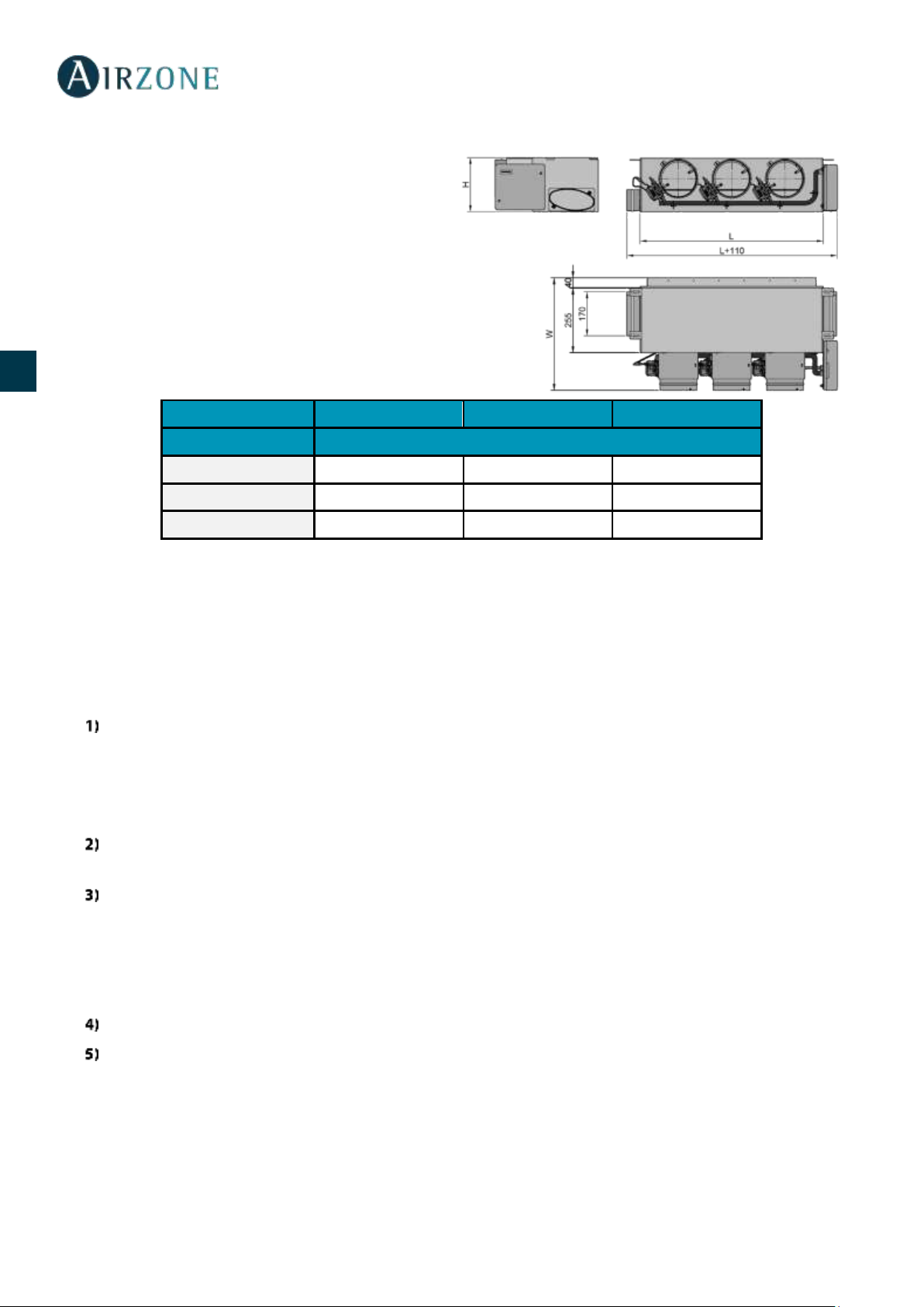
76
ES
EN
FR
IT
PT
DE
PLENUM MOTORIZZATO BASSO PROFILO (AZEZ6DAISL)
Il plenum motorizzato basso profilo Airzone include:
- Scheda centrale.
- Interfaccia di comunicazione.
- Serrande circolari da diametro 150 mm.
- Sistema di regolazione di portata manuale.
- Setto per la ventilazione meccanica controllata
(VMC), diametro 150 mm.
Variazione fino a ±3dB (A) sul livello di pressione sonora
della unità interna e peso massimo di 18 Kg.
Taglia
S M L
Nº di serrande
L x H x W (mm)
2 / 3
720 x 210 x 444
4
930 x 210 x 444
5
1140 x 210 x 444
Codice di Plenum: AZEZ6DAISL01 [Taglia] [Nº di serrande]
INSTALLAZIONE DEL SISTEMA
Seguire le seguenti indicazioni per realizzare una corretta installazione del sistema:
Realizzare tutti i collegamenti elettrici (Vedi sezione Montaggio del sistema).
- Collegare l'interfaccia di comunicazione.
- Collegare i diversi elementi del sistema (termostati, moduli ecc.).
- Alimentare la scheda centrale.
Verificare la corretta installazione e il corretto collegamento del sistema (vedi sezione Verifica dell'installazione e
del collegamento).
Configurare il sistema.
- Configurare i vari termostati del sistema (vedi sezioni Configurazioni iniziali e Configurazioni avanzate).
- Ricordare che i sistemi Airzone permettono di configurare le interfacce maestre e di zona. Da un termostato maestro
sarà possibile realizzare un cambio di Modo, definire il grado di efficienza con la funzione Eco-Adapt o selezionare le
velocità nell'unità.
Consultare il manuale per l'utente e l'installazione del sistema per qualsiasi altra consultazione.
Non ha bisogno di manutenzione.

77
ES
EN
FR
IT
PT
DE
MONTAGGIO DEL SISTEMA
MONTAGGIO EASYZONE
Importante: Si consiglia di isolare tutte le parti metalliche di Easyzone in contatto con la parte esterna per evitare la formazione
di condensa.
Ricordare: Le motorizzazioni sono numerate nel seguente modo:
INSTALLAZIONE A UNITÀ INTERNA
Collocare Easyzone nella bocchetta di mandata dell'unità e fissarlo con delle viti.
Dopo aver fissato le viti, isolare il collo del collegamento per evitare la formazione di condensa. Utilizzare strisce di materiale
isolante (lana di vetro o polietilene espanso) da 25 mm di spessore. La larghezza di queste strisce di isolamento è di 97 mm per
il plenum motorizzato standard e di 37 mm per il plenum motorizzato a basso profilo.
Fissare Easyzone al soffitto con le linguette delle estremità e con viti prigioniere.

78
ES
EN
FR
IT
PT
DE
INSTALLAZIONE DELLA SERRANDA DI BYPASS
Rimuovere la zona pretagliata delle parti laterali corrispondente al bypass con un colpo secco.
Rimuovere l'isolante che ricopre la zona del bypass con un coltello e scoprire le fessure di fissaggio del bypass.
Collocare la serranda di bypass nelle fessure e girare da sinistra verso destra fino al limite.
Fissare la serranda di bypass al plenum con una vite autofilettante (Ø3,9 mm).
INSTALLAZIONE DELLA PRESA D'ARIA DI VENTILAZIONE
Rimuovere il collo ellittico fissato con viti.
Rimuovere la lastra protettiva che ricopre la presa d'aria esterna e fissare nuovamente il collo ellittico.
Piegare o tagliare la lastra che si trova nella parte inferiore delle serrande di mandata per permettere il passaggio dell'aria.

79
ES
EN
FR
IT
PT
DE
SOSTITUZIONE DEL MOTORE
Scollegare il motore.
Allentare la vite di fissaggio con una brugola n. 3 e rimuovere il motore dalla serranda.
Collocare il nuovo motore in modo che coincida con il perno.
Girare il motore finché il secondo perno non coincide con il foro per posizionare la serranda in modo corretto.
Inserire e stringere la vite di fissaggio.
Collegare il cavo del motore.

80
ES
EN
FR
IT
PT
DE
MONTAGGIO TERMOSTATI (AZCE6BLUEFACEC / AZCE6THINKR / AZCE6LITER)
Il termostati di Airzone vengono montati in superficie mediante supporto. Si prega di ricordare che la distanza massima
raccomandabile per questi dispositivi è di 40 metri. Per fissarli alla parete è necessario seguire le seguenti indicazioni:
• Separare la parte posteriore del termostato e realizzare gli opportuni
collegamenti (AZCE6BLUEFACEC) o introdurre la batteria a bottone
(AZCE6THINKR y AZCE6LITER).
• Fissare la parte posteriore del termostato alla parete.
• Collocare il display sul supporto già fissato.
• Collocare le viti di sicurezza antivandalo per un maggior fissaggio del termostato
(opzionali).
COLLEGAMENTI A
1) Sospendere l'alimentazione dell'unità interna Daikin e quella del sistema Airzone.
2) Localizzare il collegamento P1 P2 nell'unità interna Daikin. (Dove viene collegato il termostato).
3) Collegare l'interfaccia Airzone alla porta P1 P2 dell'unità interna Daikin con il cavo fornito da Airzone.
4) Alimentare l'unità interna e il sistema Airzone. Verificare i LED dell'interfaccia (vedi sezione Autodiagnos).
5) Per un corretto funzionamento del sistema Airzone disabilitare la funzione Ripristina nei comandi Daikin (BRC1E52A,
...). Impostazioni di servizio > Impostazioni sul posto> 1e-2-01. In caso di dubbi, si prega di consultare il Manuale di
Istruzioni Daikin BRC1E52A7.
P1 - Rosso
P2 - Nero

81
ES
EN
FR
IT
PT
DE
MONTAGGIO DEL SISTEMA
SCHEDA CENTRALE INNOBUS PRO6 (AZCE6IBPRO6)
1.- Termostati Airzone
Collegare gli elementi di controllo del sistema in uno dei 3 morsetti del bus di collegamento
. Il collegamento può essere realizzato in modo bus e a stella. Rispettare il codice dei colori.
Fissare i cavi nelle torrette della scheda centrale per una maggiore sicurezza.
Verificare che sia stata inserita la batteria negli elementi radio.
2.- Alimentazione del sistema
Alimentare a 110/230 Vac la scheda centrale del sistema attraverso l'entrata dell'alimentazione
e gli elementi di controllo che hanno bisogno di un'alimentazione esterna. A tale scopo, utilizzare
il cavo da 3x1,5 mm². tare il
premistoppa se necessario e passare il cavo dal foro (Ø: 5-10 mm); fissare i cavi al morsetto
di
alimentazione.
Nº
Descrizione
Bus di collegamento Airzone
Modulo radio
SW1
Bus domotico
Interfaccia di comunicazione Daikin
Uscite del motore
Ingresso dell'allarme (normalmente chiusa)
Sonda temperatura
VMC/Caldaia
Relè On-Off AA
Alimentazione
Modulo ON/OFF (solo AZCE6IBPRO6)
Importante: È necessario utilizzare un cavo schermato
per controllare gli ingressi del modulo On/Off.
Termostato

82
ES
EN
FR
IT
PT
DE
Nel cablaggio esterno di alimentazione del sistema dovrà essere inserito un interruttore principale o un
altro mezzo di scollegamento dotato di una separazione costante in tutti i poli, secondo la
regolamentazione locale o nazionale pertinente. Se l'alimentazione principale si spegne, il sistema si
riavvierà automaticamente. Utilizzare un circuito indipendente dell'unità da controllare per
l'alimentazione del sistema.
Ricordare: collocare correttamente il coperchio della scheda centrale del sistema una volta realizzati tutti i collegamenti.
Reset del sistema
Nel caso in cui sia necessario riportare il sistema ai valori di fabbrica, mantenere premuto SW1 finché il
LED D19 non smetta di lampeggiare. Attendere che i LED ritornino nel loro stato normale per reimpostare
la configurazione iniziale.
Cambio della batteria
Per sostituire la batteria, separare il termostato dal suo supporto e
provvedere alla sostituzione della batteria (CR2450).
Importante: Si consiglia l'uso di batterie di marchi di qualità, simili a
quelle fornite. Una batteria di qualità inferiore potrebbe avere un ciclo di
vita minore.
Smaltire la batteria in un punto di raccolta per il riciclaggio adeguato.
Nota: Si prega di ricordare di togliere il sistema antivandalo prima di
rimuovere il termostato dalla parete.
VERIFICA DELL'INSTALLAZIONE E DEL COLLEGAMENTO
Verificare i seguenti item:
- Stato dei LED della scheda centrale e degli altri elementi di controllo collegati. Consultare la sezione Autodiagnosi della
scheda tecnica di ogni elemento.
- Alimentazione dei termostati cablati e radio.
CONFIGURAZIONI INIZIALI
TERMOSTATI BLUEFACE E THINK
Importante: Una volta avviato non sarà più possibile tornare indietro e sarà necessario arrivare fino alla fine del processo di
configurazione.
Lingua/Stato
Selezionare la lingua desiderata e la località. Le lingue disponibili sono: spagnolo, inglese, francese, italiano, portoghese e
tedesco.

83
ES
EN
FR
IT
PT
DE
In caso di termostati Think radio, iniziare la ricerca del canale radio :
Configurazioni dispositivi radio
- Aprire il canale radio per associare i termostati radio. A tale scopo premere SW1, il LED D19
sarà di colore rosso fisso. Una volta aperto potrà essere realizzata l'associazione in 15 minuti.
Se il tempo finisce prima del completamento dell'operazione, realizzarla di nuovo. È anche
possibile aprire il canale dell'associazione radio attraverso i termostati Blueface e Think (vedi
sezione Parametri di sistema).
IMPORTANTE: ricordare di non lasciare mai un canale aperto nella stessa installazione
simultaneamente, poiché potrebbe provocare associazioni erronee.
- Iniziare la ricerca del canale radio premendo Airzone.
Indirizzo zona
Selezionare la zona associata a questo termostato. A ogni zona corrisponde un'uscita di controllo. In questo modo, ad esempio,
la zona 1 controllerà l'uscita del motore 1.
Uscite associate
Il sistema permette di associare a una zona più di una uscita di controllo in caso di necessità, poiché è possibile gestire varie
uscite di controllo da un unico termostato.
Configurazione termostato
Selezionare il funzionamento del termostato:
- Maestro: Permette di controllare tutti i parametri dell'installazione.
- Zona: Permette di controllare solamente i parametri di zona.
Altre configurazioni
Premere per terminare il processo di configurazione iniziale, oppure, accedere al menu delle configurazioni avanzate
(indirizzo del sistema, tipi di impianto, ecc.) per effettuare altre configurazioni e/o attivare eventualmente la funzione base
(vedi sezione Configurazioni avanzate, Parametri di zona).
Blueface

84
ES
EN
FR
IT
PT
DE
Think
Importante: Utilizzare per confermare e per tornare indietro nel caso in cui l'utente si trovi nei sottomenu.
TERMOSTATO LITE
Importante: Per configurare il termostato Lite è necessario rimuoverlo dalla base. Una volta configurati i microswitch, collocarlo
nuovamente nella sua base.
Configurazioni dispositivi radio (disponible solo per termostatos radio)
Aprire il canale radio per associare i termostati radio. A tale scopo premere SW1, il LED D19 sarà di
colore rosso fisso. Una volta aperto potrà essere realizzata l'associazione in 15 minuti. Se il tempo
finisce prima del completamento dell'operazione, realizzarla di nuovo. È anche possibile aprire il
canale dell'associazione radio attraverso i termostati Blueface e Think (vedi sezione Parametri di
sistema).

85
ES
EN
FR
IT
PT
DE
IMPORTANTE: ricordare di non lasciare mai un canale aperto nella stessa installazione simultaneamente, poiché potrebbe
provocare associazioni erronee.
Indirizzo zona
Selezionare la zona associata a questo termostato alzando il microswitch della zona corrispondente.
Uscite associate
Selezionare altre uscite di controllo associate alla zona in caso di bisogno. L'indirizzo della zona sarà quello del valore minore
selezionato.
Altre configurazioni
Configurare le altre funzionalità del termostato LITE mediante il menu delle configurazioni avanzate della sua zona da un
termostato Blueface (vedi sezione Configurazioni avanzate, Parametri di zona).
Il LED lampeggerà 5 volte in verde per indicare che l'associazione è corretta. Se lampeggia una volta in rosso significa che
la zona è occupata e se lampeggia 2 volte in rosso significa che il termostato si trova fuori copertura.
Ricordare: Se è necessario cambiare il numero di zona, resettare prima di tutto il termostato e avviare la sequenza di associazione.
Reset del termostato Lite
Se si desidera ristabilire i valori di fabbrica del termostato Lite, abbassare tutti i microswitch e ricollocare il termostato nella
base. Il LED lampeggerà 2 volte in verde per confermare il completamento del reset.
VERIFICA DELLE CONFIGURAZIONI INIZIALI
Verificare i seguenti item:
- Comunicazione unità-sistema: configurare il sistema Airzone in un modo di funzionamento diverso da Stop e
accendere la zona in regime di domanda della stessa. Verificare che il modo imposto nel termostato maestro compaia
nel termostato dell'unità interna e che la temperatura impostata cambi nello stesso.
- Apertura-chiusura di serrande e uscite di controllo: accendere tutte le zone in regime di domanda.
Conseguentemente, spegnere e accendere ogni zona per verificare che le uscite di controllo associate siano corrette.
-
Ricordare: Per motivi di sicurezza l'ultima zona impiegherà 4 minuti per chiudersi.

86
ES
EN
FR
IT
PT
DE
REGOLAZIONE DELLE PORTATE
Importante: Iniziare la regolazione della portata dalle serrande centrali fino a terminare nella serranda n. 1.
REGOLAZIONE DELLA PORTATA (REG)
1. Accendere tutte le zone in regime di domanda per aprire tutte le serrande.
2. Spegnere la zona/serranda da regolare.
3. Regolare l'apertura massima desiderata con la leva REG (I/II/III/IV).
4. Accendere la zona e verificare che la portata sia corretta.
REGOLAZIONE DELL'ARIA MINIMA (A-M)
1. Accendere tutte le zone in regime di domanda per aprire tutte le serrande.
2. Regolare l'apertura minima desiderata con la leva A-M (a/b/c/d).
3. Spegnere la zona e verificare che la portata di aria minima sia corretta.
A-M
REG

87
ES
EN
FR
IT
PT
DE
CONFIGURAZIONI AVANZATE
Seguire le seguenti indicazioni per accedere al menu delle configurazioni avanzate del Blueface e del termostato Think:
Blueface
Think
In questo menu è possibile agire sui parametri di sistema e di zona.
PARAMETRI DI SISTEMA
• Indirizzo del sistema. Consente di definire il numero del sistema nella sua installazione. Mostra il valore 1 per difetto.
Il sistema mostrerà i valori di indirizzo liberi con un valore massimo di 247.
• Limiti di temperatura. Permette di selezionare la temperatura massima per il modo caldo (19 30 °C, predefinito
30 °C) e la temperatura minima per il modo freddo (18 26 °C, predefinito 18 °C) a intervalli di 1 °C. È possibile
disabilitare alcuni modi se necessario.
• Tipo di apertura. Configurazione del tipo di apertura dell'uscita della serranda. La proporzionalità regola l'apertura o
la chiusura della serranda in 4 passaggi diversi in base alla domanda di temperatura della zona, adeguando la sua
portata. È configurato come Tutto/Niente per difetto.
• Modo standby (solo per i termostati Blueface). Configurazione della logica di funzionamento degli elementi
motorizzati quando non vi è domanda nel sistema. Appare disattivato per difetto.
• Configurazione relè. Permette di modificare la logica di funzionamento del relè VMC/caldaia della scheda centrale
del sistema. (Predefinito VMC)
• Q-Adapt (solo per i termostati Think).
disponibili sono quelli di seguito indicati:
- Massimo: Il sistema lavora alla velocità più alta disponibile, indipendentemente del numero di zone aperte.
- Potenza: Il sistema lavora ad una velocità più alta che in modo Standard con lo scopo di aumentare la portata.
Tenere premuto
Tenere premuto
Tenere premuto
Premere brevemente

88
ES
EN
FR
IT
PT
DE
- Standard: Configurazione predefinita. Il sistema modifica la velocità in funzione del numero di zone aperte.
- Silenzio: Il sistema lavora a una velocità inferiore che in modo Standard con lo scopo di ridurre il rumore
- Minimo: Il sistema lavora alla velocità minima disponibile, indipendentemente del numero di zone aperte.
• Canale radio. Permette di attivare/disattivare il canale di associazione radio del sistema.
• Informazioni (solo per i termostati Think). Permette di visualizzare le informazioni relative alla zona, al sistema, ai
dispositivi e al Webserver.
• Reset sistema (disponibile solo per il termostato Blueface maestro). Permette di resettare il sistema riportandolo alle
impostazioni di fabbrica. Per configurare nuovamente i termostati accedere alla sezione Configurazioni iniziali).
PARAMETRI DI ZONA
• Uscite associate. Mostra e consente di selezionare le uscite di controllo associate al termostato.
• Configurazione termostato. Consente di configurare il termostato maestro come Maestro o Zona.
* Nota: Non è possibile effettuare la configurazione come Maestro se esiste già un altro termostato configurato come tale.
• Modo di utilizzo. Permette di configurare il termostato delle diverse zone del sistema in modo Base o Avanzato. È
configurato come Avanzato per default. I parametri che possono essere controllati in modo Base sono: ON/OFF,
temperatura impostata e velocità del ventilatore.
Se è necessario configurare nuovamente il termostato come Avanzato, accedere al menu delle configurazioni avanzate
e abilitare il modo di utilizzo Avanzato.
• Tipi di impianto. Permette di configurare le sorgenti freddo e caldo nella zona selezionata o in tutte le zone del
sistema. Le opzioni da configurare sono:
- Aria: abilità il modo caldo/freddo ad aria nella zona selezionata.
- Spento: disabilita la sorgente caldo/freddo nella zona selezionata.
• Offset. Correzione della temperatura ambiente delle diverse zone del sistema in modo freddo e in modo caldo, con
un fattore di correzione compreso tra - 2,5 °C e 2,5 °C a intervalli di 0,5 °C. Si trova configurato a 0 °C per default.
• Reset termostato (non disponibile nelle zone remote). Consente di resettare il termostato riportandolo al menu delle
configurazioni iniziali.

89
ES
EN
FR
IT
PT
DE
AUTODIAGNOSI
SCHEDA CENTRALE INNOBUS PRO6 (AZCE6IBPRO6)
INTERFACCIA DI COMUNICAZIONE DAIKIN (AZX6GTCDA1)
Significato
D1
Ricezione dati dal bus domotico
Lampeggia
Verde
D2
Trasmissione dati al bus domotico
Lampeggia
Rosso
D3
Attività della scheda
Lampeggia
Verde
D4
Trasmissione dati al bus di collegamento Airzone
Lampeggia
Rosso
D5
Ricezione dati dal bus di collegamento Airzone
Lampeggia
Verde
D6
On/Off macchina
Lampeggia
Verde
D7
VMC- Caldaia
Lampeggia
Verde
D10
Ricezione di dati via radio
Commuta
Verde
D11
Alimentazione della scheda
Fisso
Rosso
D18
Elemento associato
Fisso
Verde
D19
Canale di associazione attivo
Fisso
Rosso
Apertura motorizzazioni
Acceso
Verde
Chiusura motorizzazioni
Acceso
Rosso
Significato
D3
Attività del microprocessore
Lampeggia
Verde
D8
Trasmissione dei dati verso il sistema Airzone
Lampeggia
Rosso
D9
Ricezione dei dati dal sistema Airzone
Lampeggia
Verde
D11
Alimentazione dell'interfaccia
Fisso
Rosso
D34
Trasmissione dei dati verso l'unità interna
Lampeggia
Rosso
D35
Ricezione dei dati dall'unità interna
Lampeggia
Verde

90
ES
EN
FR
IT
PT
DE
TERMOSTATI BLUEFACE E THINK (AZCE6BLUEFACEC / AZCE6THINKR)
TERMOSTATO LITE RADIO (AZCE6LITER)
Significato
Error 1
Errore di comunicazione tra termostato e scheda centrale
Error 5
Sonda di temperatura in circuito aperto
Error 6
Sonda di temperatura in cortocircuito
Error 8
Termostato Lite non trovato
Error 9
Errore di comunicazione interfaccia - sistema
Error 11
Errore di comunicazione interfaccia - unità
Significato
Lampeggia di rosso velocemente
Errore di comunicazione scheda centrale

91
ES
EN
FR
IT
PT
DE
ÍNDICE
Precauções e política ambiental ............................................................................................................................................................................................................ 92
Precauções ............................................................................................................................................................................................................................................. 92
Política medioambiental.................................................................................................................................................................................................................... 92
Requisitos gerais......................................................................................................................................................................................................................................... 93
Elementos do sistema ............................................................................................................................................................................................................................... 94
Central do sistema Innobus Pro6 (AZCE6IBPRO6) ..................................................................................................................................................................... 94
Características técnicas ................................................................................................................................................................................................................ 94
Gateway de comunicação Daikin (AZX6GTCDA1) ..................................................................................................................................................................... 95
Características técnicas ................................................................................................................................................................................................................ 95
Termostato inteligente Blueface (AZCE6BLUEFACEC) ............................................................................................................................................................. 95
Características técnicas ................................................................................................................................................................................................................ 96
Termostato Think rádio (AZCE6THINKR) ....................................................................................................................................................................................... 96
Características técnicas ................................................................................................................................................................................................................ 96
Termostato Lite rádio (AZCE6LITER) .............................................................................................................................................................................................. 97
Características técnicas ................................................................................................................................................................................................................ 97
Plenum motorizado padrão (AZEZ6DAIST) ................................................................................................................................................................................. 97
Plenum motorizado baixo perfil (AZEZ6DAISL) ......................................................................................................................................................................... 98
Instalação do sistema ................................................................................................................................................................................................................................ 98
Montagem do sistema .............................................................................................................................................................................................................................. 99
Montagem Easyzone .......................................................................................................................................................................................................................... 99
Montagem na unidade interior ....................................................................................................................................................................................................... 99
Montagem da comporta bypass ................................................................................................................................................................................................... 100
Montagem da entrada de ar de ventilação................................................................................................................................................................................ 100
Substituição do motor ...................................................................................................................................................................................................................... 101
Montagem termostatos (AZCE6BLUEFACEC / AZCE6THINKR / AZCE6LITER) ................................................................................................................. 102
Conexão a unidade interior .................................................................................................................................................................................................................. 102
Montagem do sistema ............................................................................................................................................................................................................................ 103
Central do sistema Innobus Pro6 (AZCE6IBPRO6) ................................................................................................................................................................... 103
Reset do sistema ................................................................................................................................ .......................................................................................... 104
Alteração da bateria .................................................................................................................................................................................................................... 104
Verificação da montagem e conexão .......................................................................................................................................................................................... 104
Configuração inicial ................................................................................................................................................................................................................................. 104
termostatos Blueface e Think ......................................................................................................................................................................................................... 104
termostato Lite ................................................................................................................................................................................................................................... 107
Reset termostato Lite ................................................................................................................................................................................................................. 107
Verificação da configuração inicial ............................................................................................................................................................................................... 107
Regulação do fluxo .................................................................................................................................................................................................................................. 108
Ajuste de Fluxo (REG) ........................................................................................................................................................................................................................ 108
Ajuste de ar mínimo (A-M) .............................................................................................................................................................................................................. 108
Configuração avançada ......................................................................................................................................................................................................................... 109
Parâmetros do sistema ..................................................................................................................................................................................................................... 109
Parâmetros de zona .......................................................................................................................................................................................................................... 110
Autodiagnóstico ....................................................................................................................................................................................................................................... 111
Central do sistema Innobus Pro6 (AZCE6IBPRO6) ................................................................................................................................................................... 111
Gateway de comunicação Daikin (AZX6GTCDA1) ................................................................................................................................................................... 111
Termostatos Blueface y Think (AZCE6BLUEFACEC / AZCE6THINKR) ................................................................................................................................. 112
Termostato Lite rádio (AZCE6LITER) ............................................................................................................................................................................................ 112

92
ES
EN
FR
IT
PT
DE
PRECAUÇÕES E POLÍTICA AMBIENTAL
PRECAUÇÕES
Para sua segurança e de seus dispositivos, siga as seguintes instruções:
• Não manipule o sistema com as mãos molhadas ou húmidas.
• Faça todas as conexões ou desconexões com o sistema de climatização sem alimentá-lo.
• Tenha o cuidado de não fazer nenhum curto-circuito nas conexões do sistema.
POLÍTICA MEDIOAMBIENTAL
Nunca deite fora esse equipamento com o lixo doméstico. Caso não sejam tratados
adequadamente, os produtos elétricos e eletrônicos podem liberar substâncias que causam
danos ao meio ambiente. A imagem de um recipiente riscado ao meio indica coleta seletiva
de dispositivos elétricos, que são tratados de maneira diferente do lixo urbano. Para uma
gestão ambiental correta, no final de sua vida útil, os equipamentos elétricos deverão ser
levados a centros de coleta.
As peças desses equipamentos poderão ser recicladas. Portanto, respeite a regulamentação
em vigor sobre proteção ambiental.
Entregue o equipamento que não será mais utilizado ao seu distribuidor ou a um centro de
coleta especializado.
Os infratores estarão sujeitos às sanções e medidas estabelecidas pela Lei de proteção do
meio ambiente.
Para acessar toda a documentação técnica, autodiagnósticos, perguntas frequentes, vídeos de
montagem e configuração do sistema, certificados e a declaração de conformidade, acesse a secção
de Produtos da web Myzone: myzone.airzone.es/productos/
Para acessar a declaração de conformidade, acesse a:
http://doc.airzone.es/producto/Gama_AZ6/Airzone/Certificados/Declarat
ion_of_conformity_AZ6.pdf
Através do presente documento, Corporación Empresarial Altra, S.L., declara que AZEZ6DAIxxxxxxx cumpre os requisitos
básicos e outras disposições relevantes da diretiva 2014/53/EU.

93
ES
EN
FR
IT
PT
DE
REQUISITOS GERAIS
Siga rigorosamente as indicações deste manual:
• O sistema deve ser instalado por um técnico qualificado.
• Verifique se as unidades a serem controladas foram instaladas de acordo com os requisitos do fabricante e funcionam
corretamente antes de instalar o sistema Airzone.
• Localize e conecte todos os elementos da sua instalação conforme a regulamentação eletrónica local vigente.
• Verifique se a instalação de climatização a ser controlada cumpre a normativa local vigente.
• É necessário o uso de um termostato Blueface para utilizar todas as funcionalidades do sistema Airzone.Siga as
seguintes recomendações para posicionar os termostatos:
• Faça todas as conexões sem alimentação.
• Para a conexão de comunicação com o sistema, utilize o cabo Airzone: cabo blindado e trançado, formado por 4 fios
(2x0,22 mm2 + 2x0,5 mm2).
• Não coloque o barramento do sistema próximo a linhas de força, iluminação fluorescente, motores, etc., para que não
haja interferência na comunicação.
• Respeite a polaridade da ligação de cada dispositivo. Uma ligação incorreta pode danificar o produto.
• Para elementos com alimentação externa a 110/230
barramento para comunicação. - .
• Para elementos com alimentação externa a 110/230 Vac, respeite a polaridade da ligação. Uma ligação à terra incorreta
pode causar descargas elétricas.
• En el cableado de alimentación externo del sistema deberá incorporarse, según la reglamentación local y nacional
pertinente, un interruptor principal u otro medio de desconexión que tenga una separación constante en todos los
polos. El sistema se reiniciará automáticamente si se apaga la alimentación principal.
• Após configurar o sistema Airzone, verifique se a pressão estática no equipamento de condutas está de acordo com
as condições da rede de distribuição de ar onde está instalado (consulte o manual do fabricante do equipamento se
precisar modificar este parâmetro).

94
ES
EN
FR
IT
PT
DE
ELEMENTOS DO SISTEMA
CENTRAL DO SISTEMA INNOBUS PRO6 (AZCE6IBPRO6)
Equipamento configurável eletrónico responsável pela gestão do sistema, mediante
dispositivos com cabos e sem fios. Montagem em superfície.
Funcionalidades:
• Controlo e gestão do estado dos termostatos, até 6 zonas.
• Salidas de alimentación para elementos motorizados.
• Módulo de control On/Off zona remota, hasta 6 zonas.
• Salida de relé configurable como ventilación mecánica (VMC) o caldera.
• Gestión de pasarelas de control a equipos de climatización.
• Comunicación con equipos de control integral de la instalación.
• Comunicaciones con otros sistemas de control externo mediante bus de integración.
Características técnicas
Alimentaçao e consumo
Barramento de conexão Airzone
Tipo de alimentação
Vac
Nº de portas
3
V max
110 / 230 V
Cabo blindado e trançado
2 x 0,22 + 2x0,5 mm2
I max
250 mA
V max
12 V
Frequência
60/50 Hz
Barramento domótico
Consumo em stand-by
400 mW
Nº de portas
1
Consumo máximo
25 W
Cabo blindado e trançado
2 x 0,22 + 2x0,5 mm2
Proteção sobrecorrente módulo
250 mA
Protocolo de comunicação
MODBUS RS-485
Par 19200 bps
Comunicaçoes rádio
Salidas de motor
Protocolo de comunicação
Airzone
Nº de salidas
6
Frequência
868 MHz
Nº máximo de motorizaciones por
salidas
2
Potência de radiação
5 dBm
Vmax
± 12 V
Distância máxima em espaço livre
40 m
Imax
150 mA
Temperatura de operaçao
Saídas de relé
Armazenamento
-
Nº de relés
2
Funcionamento V max
24 / 48 V
Aspectos mecânicos
I max
1 A
Grau de proteção
IP 20
Peso
616 g
Dimensões (WxHxD)
195x180x55,5 mm
Type
Airzone Central V1.3
Licence
215562
Application
Variable air volume system (without h/c coil)
Heating
Cooling
Control accuracy (K)
0.3
0.3
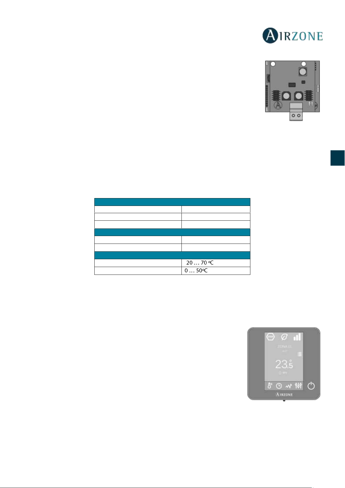
95
ES
EN
FR
IT
PT
DE
GATEWAY DE COMUNICAÇÃO DAIKIN (AZX6GTCDA1)
Gateway para a gestão de equipamentos de ar condicionado Daikin compatíveis através dos
sistemas de controlo Airzone. Alimentação através da unidade interior. Montagem e ligação sobre
porta de máquina dos dispositivos Airzone habilitados. Produto desenvolvido e testado com o
fabricante.
Funcionalidades:
• Comunicação bidirecional dos parâmetros básicos de controlo (on/off, temperatura de
referência, modo de funcionamento e velocidade do ventilador) em função da demanda do
sistema de controlo Airzone.
• Controlo de até 5 velocidades de forma automática, o que permite (em geral) o
funcionamento sem bypass.
• Ajuste da temperatura de referência em função das temperaturas selecionadas nos termostatos Airzone e do algoritmo Eco-
Adapt.
• Leitura da temperatura de funcionamento do equipamento.
• Leitura de avisos e erros do equipamento controlado.
• Controlo mestre da unidade.
Características técnicas
TERMOSTATO INTELIGENTE BLUEFACE (AZCE6BLUEFACEC)
Interface gráfica em cores com ecrã capacitivo e acabamento em aço e cristal para o controlo de zona em um sistema Airzone.
Alimentado através da central do sistema. Disponível em branco e negro.
Funcionalidades:
• 6 idiomas disponíveis (espanhol, inglês, francês, italiano, alemão e português).
• Controlo de temperatura, modo de funcionamento e velocidade do ventilador
(termostato mestre e instalação fancoil).
• Leitura da temperatura ambiente e humidade relativa da zona.
• Função Eco-Adapt.
• Função Sleep.
• Programações horárias de temperatura e modo.
• Acesso remoto a outras zonas do sistema.
Alimentaçao e consumo
Alimentação
Unidade interior
V max
16 Vdc
I max
25 mA
Comunicaçao
Tipo de cabo
Trançado e blindado
Fios de comunicação
2 x 0,75 mm2
Temperaturas de operaçao
Armazenamento
-
Funcionamento

96
ES
EN
FR
IT
PT
DE
Características técnicas
TERMOSTATO THINK RÁDIO (AZCE6THINKR)
Interface gráfica com ecrã de tinta de baixo consumo, botões capacitivos e acabamento em aço e cristal para o controlo de
zona em um sistema Airzone. Comunicação via rádio. Alimentado através de batería de bateria de botão CR2450. Disponível
em branco e negro.
Funcionalidades:
• 6 idiomas disponíveis (espanhol, inglês, francês, italiano, alemão e português).
• Controlo de temperatura, modo de funcionamento (termostato mestre) e
velocidade do sistema (termostato mestre e instalação fancoil).
• Leitura da temperatura ambiente e humidade relativa da zona.
• Função Sleep.
• Acesso remoto a outras zonas do sistema.
Características técnicas
Alimentaçao e consumo
Temperatura de operaçao
Tipo de alimentação
Vdc
Armazenamento
-
V max
12 V
Funcionamento
I max
145 mA
Intervalo da temperatura de
referência
Consumo em stand-by
0,876 W
Precisão de leitura
±0,1 ºC
Consumo máximo
1,74 W
Precisão de representação
±0,1 ºC
Conexão e comunicaçao
Humidade relativa
±4 %
Tipo de cabo
Trançado e blindado
Aspectos mecânicos
Fios de comunicação
2 x 0,22 mm2
Montagem
Em superfície mediante suporte
Fios de alimentação
2 x 0,5 mm2
Grau de proteção
IP 20
Distância máxima
40 m
Tipo de sonda
Airzone_NTC_10K
Peso
198 g
Alimentaçao e consumo
Temperaturas de operaçao
Tipo de alimentação
Vdc
Almacenaje
-
V max
3,3 V
Funcionamento
I max
30 mA
Intervalo da temperatura de
referência
Bateria
CR2450
Precisão de leitura
±0,1 ºC
Vida útil da bateria
2 anos
Precisão de representação
±0,1 ºC
Consumo em Stand-by
0,01 mW
Humidade relativa
±4 %
Consumo máximo
100 mW
Aspectos mecànicos
Conexão e comunicaçao
Montagem
Em superficie mediante suporte
Frequência de comunicação
868 MHz
Grau de proteção
IP 20
Potência máxima
0 dBm
Tipo de sonda
Airzone_NTC_10K
Distância máxima em espaço livre
40 m
Peso
180 g
Dimensões (WxHxD)
92x 92x15,85 mm

97
ES
EN
FR
IT
PT
DE
TERMOSTATO LITE RÁDIO (AZCE6LITER)
Termostato com botões capacitivos e acabamento em aço e cristal para o controlo de
temperatura de zona em um sistema Airzone. Comunicação vía rádio. Alimentado através de
bateria de botão CR2450. Disponível em branco e negro.
Funcionalidades:
• On/Off da zona.
• Controlo de temperatura de referência, em intervalos de 1°C, até o máximo de ±3°C.
• Leitura da temperatura ambiente e humidade relativa.
Características técnicas
PLENUM MOTORIZADO PADRÃO (AZEZ6DAIST)
O plenum motorizado padrão Airzone inclui:
- Central do sistema.
- Gateway de comunicação.
- Comportas circulares de 200 mm de diâmetro.
- Sistema de regulação manual de fluxo.
- Entrada para ventilação mecânica controlada
(VMC), diâmetro equivalente de 150 mm.
Variação de até ±3 dB(A) sobre o nível de pressão sonora
da unidade interior e peso máximo de 18 kg.
Tamanho
XS S M L XL
Nº de
comportas
L x H x W (mm)
2 / 3
930 x 300 x 454
930 x 300 x 454
4
1140 x 300 x 454
1140 x 300 x 454
5
1425 x 300 x 454
1425 x 300 x 454
1425 x 300 x 454
6
1638 x 300 x 454
1638 x 300 x 454
7 / 8
1425 x 515 x 454
1425 x 515 x 454
Código de Plenum: AZEZ6DAIST07 [Tamanho] [Nº de comportas]
Alimentaçao e consumo
Temperaturas de operaçao
Tipo de alimentação
Vdc
Armazenamento
-
V max
3,3 V
Funcionamento
I max
30 mA
Intervalo da temperatura de
referência
Bateria
CR2450
Precisão de leitura
±0,1 ºC
Vida útil da bateria
2 anos
Precisão de leitura
±0,1 ºC
Consumo em Stand-by
0,01 mW
Humidade relativa
±4 %
Consumo máximo
100 mW
Aspectos mecânicos
Conexão e comunicaçao
Montagem
Em superfície mediante suporte
Frequência de comunicação
868 MHz
Grau de proteção
IP 20
Potência máxima
0 dBm
Tipo de sonda
Airzone_NTC_10K
Distância máxima em espaço livre
40 m
Peso
184 g
Dimensões (WxHxD)
92x 92x15,85 mm

98
ES
EN
FR
IT
PT
DE
PLENUM MOTORIZADO BAIXO PERFIL (AZEZ6DAISL)
O plenum motorizado de baixo perfil Airzone inclui:
- Central do sistema.
- Gateway de comunicação.
- Comportas circulares de 150 mm de diâmetro.
- Sistema de regulação manual de fluxo.
- Entrada para ventilação mecânica controlada
(VMC), diâmetro equivalente de 150 mm.
Variação de até ±3 dB(A) sobre o nível de pressão sonora
da unidade interior e peso máximo de 18 kg.
Tamanho
S M L
Nº de comportas
L x H x W (mm)
2 / 3
720 x 210 x 444
4
930 x 210 x 444
5
1140 x 210 x 444
Código de Plenum: AZEZ6DAISL01 [Tamanho] [Nº de comportas]
INSTALAÇÃO DO SISTEMA
Para instalar o sistema corretamente, siga os passos a seguir:
Faça todas as conexões elétricas (Ver secção Montagem e conexão).
- Conecte o gateway de comunicação.
- Conecte os diferentes elementos do sistema (termostatos, módulos, etc.)
- Alimente a central.
Verifique se a montagem e a conexão do sistema estão corretas (Ver secção Verificação de montagem e conexão).
Configure o sistema.
- Configure os diferentes termostatos do sistema (Ver as secções Configuração inicial e Configuração avançada).
- Lembre-se de que os sistemas Airzone permitem a configuração de interfaces mestras e de zonas. A partir de um
termostato mestre, poderá realizar uma troca de Modo, definir o grau de eficiência com a função Eco-Adapt ou
selecionar as velocidades do seu equipamento.
Consulte o manual de usuário e instalação do sistema caso tenha qualquer outra dúvida.
Não requer manutenção.

99
ES
EN
FR
IT
PT
DE
MONTAGEM DO SISTEMA
MONTAGEM EASYZONE
Importante: Recomenda-se isolar todas as peças metálicas do Easyzone que ficam em contacto com o exterior para evitar
condensação.
Lembre-se: As motorizações estão numeradas do seguinte modo:
MONTAGEM NA UNIDADE INTERIOR
Posicione o Easyzone na boca de impulsão do equipamento e fixe-o com parafusos.
Depois de fixar os parafusos, isole o encaixe de conexão para evitar a formação de condensação. Utilize faixas de material
isolante (lã de vidro ou de espuma de polietileno) de 25 mm de espessura. A largura destas faixas de isolamento é de 97 mm
para o plenum motorizado padrão e de 37 mm para o plenum motorizado baixo perfil.
Fixe o Easyzone ao teto através das linguetas das extremidades com hastes rosqueadas.

100
ES
EN
FR
IT
PT
DE
MONTAGEM DA COMPORTA BYPASS
Com um golpe seco, retire a área pré-cortada das laterais correspondentes ao bypass.
Com uma lâmina, retire o isolante que cobre a zona do bypass e descubra as suas ranhuras de fixação.
Encaixe a comporta de bypass nas ranhuras e gire da esquerda para a direita até chegar ao limite.
Fixe a comporta de bypass no plenum com um parafuso rosca-chapa (Ø3,9 mm).
MONTAGEM DA ENTRADA DE AR DE VENTILAÇÃO
Retire o encaixe elíptico fixado com parafusos.
Retire a chapa de proteção que cobre a entrada de ar exterior e fixe novamente o encaixe elíptico.
Dobre ou retire a tampa que se encontra na parte inferior das comportas de impulsão para permitir a passagem de ar.
 Loading...