

Page 1

Installation´s Manual
rebmuNegaPdraobpilC
Page 2

TABLE OF CONTENTS
Overview .........................................................................................................................................................................................................................................3
Outline and Features ............................................................................................................................................................................................................3
System Outline .............................................................................................................................................................................................................................3
Specifications and Device Elements ...............................................................................................................................................................................4
Functional Specifications .........................................................................................................................................................................................................5
Introduction .............................................................................................................................................................................................................................5
Available services ...................................................................................................................................................................................................................5
Installation and Configuration ...............................................................................................................................................................................................6
Installation on the Control Board ....................................................................................................................................................................................6
BACnet Interface Configuration .......................................................................................................................................................................................6
Status Menu .......................................................................................................................................................................................................................6
Settings Menu ...................................................................................................................................................................................................................7
Device ID .............................................................................................................................................................................................................................7
Objects .............................................................................................................................................................................................................................................8
Supported Object Type .......................................................................................................................................................................................................8
Objects list ................................................................................................................................................................................................................................8
Flexa 3.0 / Innobus Pro6 / Easyzone Systems .......................................................................................................................................................9
Acuazone / Innobus Pro32 Systems ...................................................................................................................................................................... 11
Detailed description of the objects ................................................................................................................................................................................... 19
Common to all objects...................................................................................................................................................................................................... 19
Z# Alarm Input ..................................................................................................................................................................................................................... 19
Z# Radiant Stage ................................................................................................................................................................................................................. 19
Air/Radiant Demand .......................................................................................................................................................................................................... 19
Z# On/Off ............................................................................................................................................................................................................................... 19
Z# Room Temperature ...................................................................................................................................................................................................... 19
Z# Humidity .......................................................................................................................................................................................................................... 19
Z# Set point ........................................................................................................................................................................................................................... 20
Z# Operation Mode ............................................................................................................................................................................................................ 20
Z# Fancoil Speed ................................................................................................................................................................................................................. 20
Troubleshooting ....................................................................................................................................................................................................................... 21
The Airzone System does not detect the Airzone BACnet Interface .............................................................................................................. 21
The Airzone BACnet Interface cannot be connected (I) ...................................................................................................................................... 21
The Airzone BACnet Interface cannot be connected (II) ..................................................................................................................................... 21
How to set the PC’s IP Address ...................................................................................................................................................................................... 22
ES
EN
FR
IT
PT
DE
2
Page 3
OVERVIEW
OUTLINE AND FEATURES
The Airzone BACnet Interface Board allows a Building Management System to control all variables of the Airzone systems.
The BACnet interface uses a standard open protocol based on ASHRAE Standard 135, and its objects are compatible with:
- BACnet (ANSI /ASHRAE-135)
ES
- BACnet/IP (ISO16484-5)
The Airzone BACnet Interface is a Plug&Play device for Airzone systems, and it allows controlling and monitoring the
following variables:
• Occupancy contact and window contact status of each zone.
• Radiant stage status of each zone and air and radiant demand of the system.
• On/Off control for each zone.
• Room temperature and humidity of each zone.
• Set point setting for Cooling and Heating for each zone.
• Operation Mode Control status.
• Fan status and Fan Speed.
SYSTEM OUTLINE
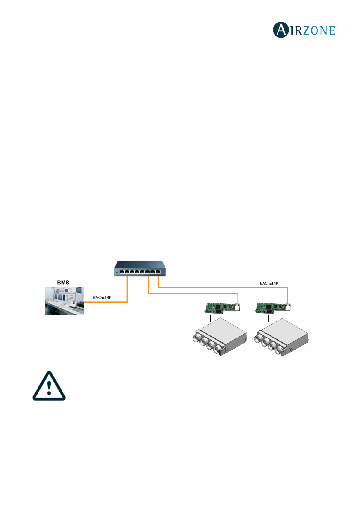
BACnet typical layouts is as follows:
EN
FR
IT
PT
DE
IMPORTANT: It is required to install one Airzone BACnet Interface for each Airzone System.
3
Page 4

Ethernet
5 to 90%
(non-condensing)
W
H
D
Meaning
SPECIFICATIONS AND DEVICE ELEMENTS
Power supply and consumption
Type of power supply
V máx.
I máx.
Maximum consumption
Operative temperatures
Storage
Operation
Operating humidity range
Vac
12 V supplied from the
Control Board
IP address by default
Type of cable
UTP cat 6
Standard T568B
DHCP
200 mA Mehanical aspects
1.8 W
Dimensions (WxHxD)
130x40x39.5 mm
-20 to 70 °C
0 to 50°C
Ethernet
Automation bus
ES
EN
FR
IT
PT
DE
Meaning
D5
D4
D7
D8
D9
D10
D11
D12
D13
D15
Data reception from automation bus Blinking
Configured as IP address through DHCP On
Ethernet connected
Ethernet activity
Data transmission from automation Blinking
Microswitch performance
Connected to the Internet
Network data transmission
Network data reception
Configured as Fixed IP address Off
Power supply Solid Red
Blinking
Blinking
Blinking
Blinking
Blinking
Blinking
Green
Yellow
Red
Green
Green
Green
Red
Green
Red
4
Page 5
FUNCTIONAL SPECIFICATIONS
INTRODUCTION
When the AirzoneBACnet Interface is used in a BACnet/IP network, it operates as a BACnet interpreter using the services defined
by the BACnet to return the status of the Airzone system. It also sends configuration commands to them, in response to requests
from a BACnet building management system (BMS) (i.e., BACnet client) which support the BACnet (ISO16484-5,
ANSI/ASHRAE135) protocol.
The Airzone BACnet Interface is a plug and play device, which, when connected to the Main Control Board and to a BACnet
network, it configures itself and configures the main board to work with the BACnet network.
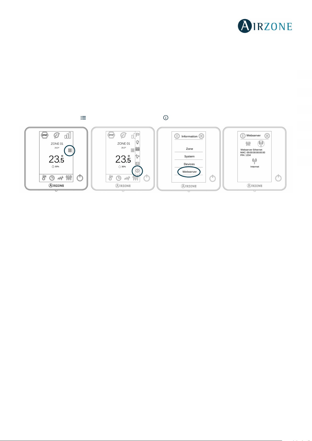
When the Airzone BACnet Interface is connected to the Main Control Board, a new item appears in the user menu. From the
main screen, press the icon , select the Information parameter and press the Webserver menu.
ES
EN
FR
IT
PT
DE
AVAILABLE SERVICES
- Read Property.
- Multiple Read Property.
- Write Property.
- Multiple Write Property.
- COV (Change of Value).
- Dynamic Device Binding (who-is, i-am, who-has, i-have).
- DCC (Device Communication Control).
- UTC Time synchronization.
Note: The values of the parameters are updated every second.
5
Page 6
INSTALLATION AND CONFIGURATION
INSTALLATION ON THE CONTROL BOARD
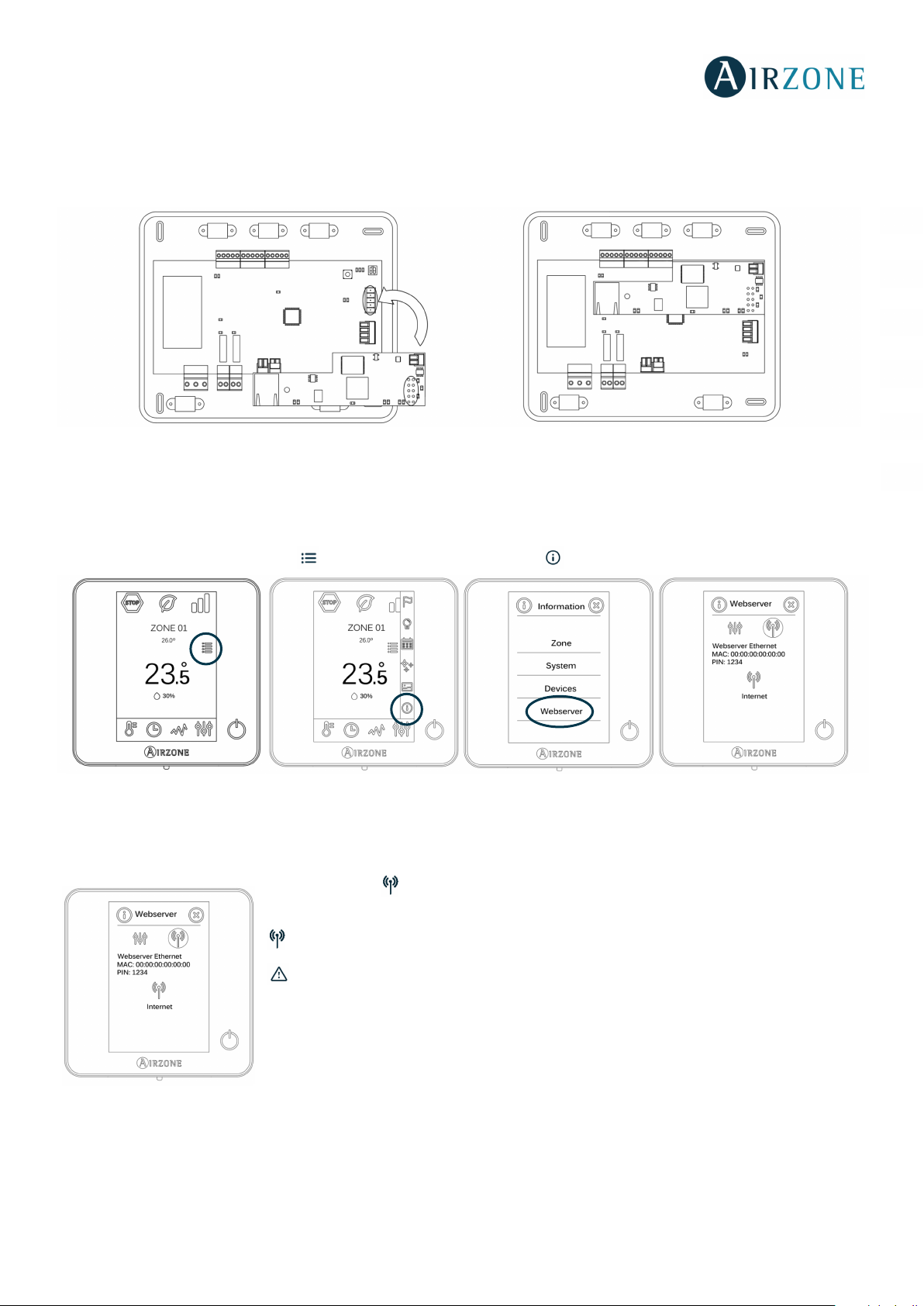
The Airzone BACnet Interface connects to the Airzone Main Control Board using the automation bus.
The Ethernet cable should be connected to the Airzone BACnet Interface gently. Once the control board has the interface
connected, it will auto-detect the presence of the BACnet Interface and automatically set the parameters to enable the BACnet
operation.
BACNET INTERFACE CONFIGURATION
ES
EN
FR
IT
PT
DE
From the main screen, press the icon , select the Information parameter and press on the Webserver menu.
Keep in mind: For proper operation, Airzone systems must be powered up before the indoor unit.
Status Menu
The status menu , gives information about the MAC and PIN of the device, as well as the
connection status:
The internet connection is correct.
There is no internet connection, check the connection between the BACnet interface and
the router and the status of the router.
6
Page 7

Settings Menu
For the correct identification at the BACnet/IP network and the correct functioning of the
Airzone BACnet Interface, it may be necessary the modification of the following configuration
parameters:
- IP Address (configured by default as DHCP)
- Subnet Mask
- Gateway
ES
EN
FR
IT
Device ID
For the correct identification at the BACnet/IP network and the correct functioning of the Airzone BACnet Interface, it may be
necessary the modification of the device ID (1000 by default). That property can only be modified through the BACnet platform.
PT
DE
7
Page 8

OBJECTS
SUPPORTED OBJECT TYPE
Supported Airzone System monitoring/control items are mapped to the standard object types defined by the BACnet.
Object Type Supported Airzone management point
Accumulator 23
Analog-Input 0 √ Measured room temperature and humidity of the zones
ES
EN
Analog-Output 1
Analog-Value 2 √ Zone Set point temperature
Averaging 18
Binary-Input 3 √ Alarms (window and occupancy contact)
Binary-Output 4 √ Radiant stage and air and radiant demand
Binary-Value 5 √ On and off of the zone
Calendar 6
Command 7
Device 8 √
Event-Enrollment 9
File 10
Group 11
Life-Safety-Point 21
Life-Safety-Zone 22
Loop 12
Multistate-Input 13
Multistate-Output 14 √ Operating mode (setting) and user mode (setting)
FR
IT
PT
DE
Multistate-Value 19 √ Fancoil Speed (setting)
Notification-Class 15
Program 16
Schedule 17
Trend-Log 20
OBJECTS LIST
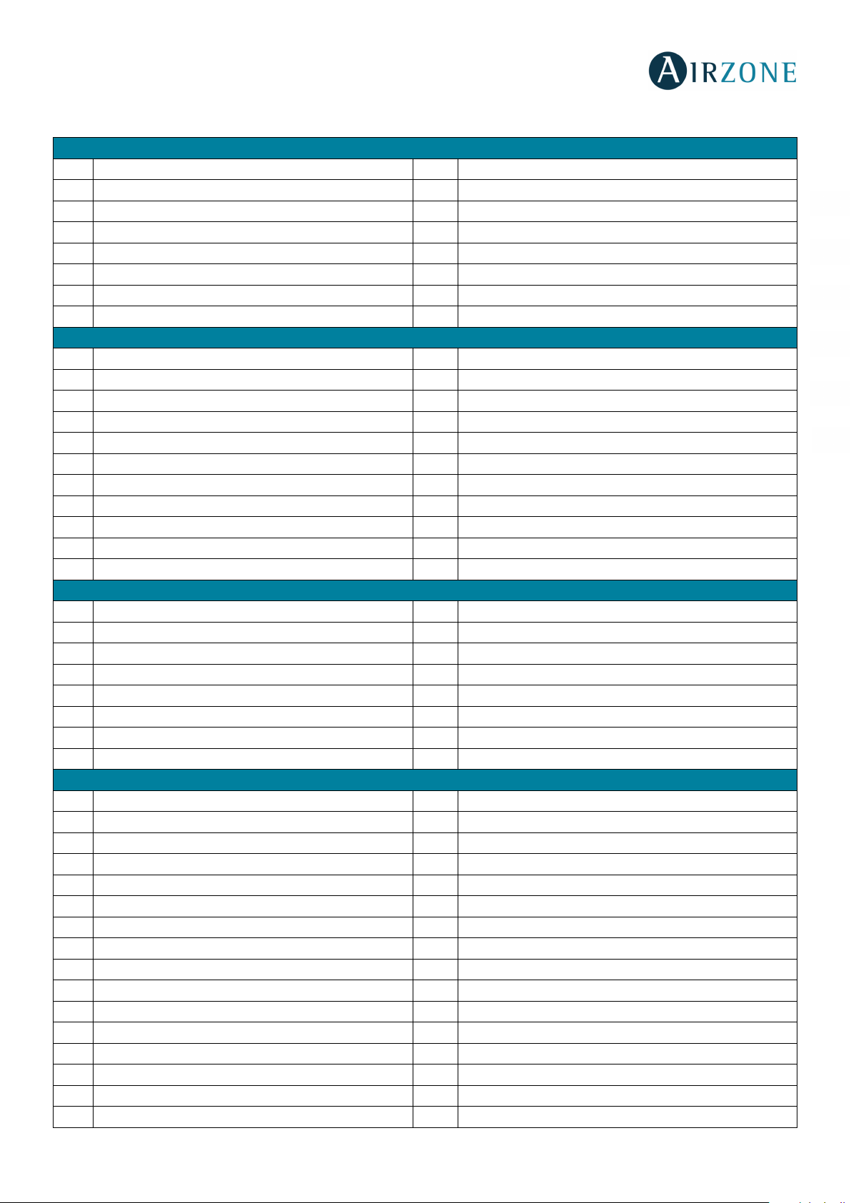
Below is the full list of objects available in the Airzone BACnet Interface. The availability of the communication objects depends
on the Airzone system configuration, and on the number of zones in the system.
The availability of the communication object in the Airzone system is indicated in the parameter "out of service" of each
communication object indicating whether it is available or not in the system.
The communication object will only have correct/valid values when the "out of service" is FALSE.
*Note: R: Read and W: Write
8
Page 9
0 à Deactivated
1 à Activated
0 à Deactivated
1 à Activated
0 à Deactivated
1 à Activated
0 à Deactivated
1 à Activated
0 à Deactivated
1 à Activated
0 à Deactivated
1 à Activated
0 à Deactivated
1 à Activated
0 à Deactivated
1 à Activated
0 à Off
1 à On
0 à Off
1 à On
0 à Off
1 à On
0 à Off
1 à On
0 à Off
1 à On
0 à Off
1 à On
0 à Off
1 à On
0 à Off
1 à On
0 à Deactivated
1 à Activated
0 à Deactivated
1 à Activated
0 à Deactivated
1 à Activated
0 à Off
1 à On
0 à Off
1 à On
0 à Off
1 à On
0 à Off
1 à On
0 à Off
1 à On
0 à Off
1 à On
0 à Off
1 à On
0 à Off
1 à On
Flexa 3.0 / Innobus Pro6 / Easyzone Systems
Binary-input
0 Z1 Window alert R
1 Z2 Window alert R
2 Z3 Window alert R
3 Z4 Window alert R
4 Z5 Window alert R
5 Z6 Window alert R
6 Z7 Window alert R
7 Z8 Window alert R
Binary-output
0 Z1 Radiant On/OFF R
1 Z2 Radiant On/OFF R
2 Z3 Radiant On/OFF R
3 Z4 Radiant On/OFF R
4 Z5 Radiant On/OFF R
5 Z6 Radiant On/OFF R
6 Z7 Radiant On/OFF R
7 Z8 Radiant On/OFF R
8 Cooling air demand R
9 Heating air demand R
10 Heating radiant demand R
Binary-value
0 Z1 On/Off R/W
1 Z2 On/Off R/W
2 Z3 On/Off R/W
3 Z4 On/Off R/W
4 Z5 On/Off R/W
5 Z6 On/Off R/W
6 Z7 On/Off R/W
7 Z8 On/Off R/W
Analog-input
0 Z1 Ambient temperature R 10 -35 °C
1 Z1 Humidity R 0 -100
2 Z2 Ambient temperature R 10 -35 °C
3 Z2 Humidity R 0 -100
4 Z3 Ambient temperature R 10 -35 °C
5 Z3 Humidity R 0 -100
6 Z4 Ambient temperature R 10 -35 °C
7 Z4 Humidity R 0 -100
8 Z5 Ambient temperature R 10 -35 °C
9 Z5 Humidity R 0 -100
10 Z6 Ambient temperature R 10 -35 °C
11 Z6 Humidity R 0 -100
12 Z7 Ambient temperature R 10 -35 °C
13 Z7 Humidity R 0 -100
14 Z8 Ambient temperature R 10 -35 °C
15 Z8 Humidity R 0 -100
ES
EN
FR
IT
PT
DE
9
Page 10
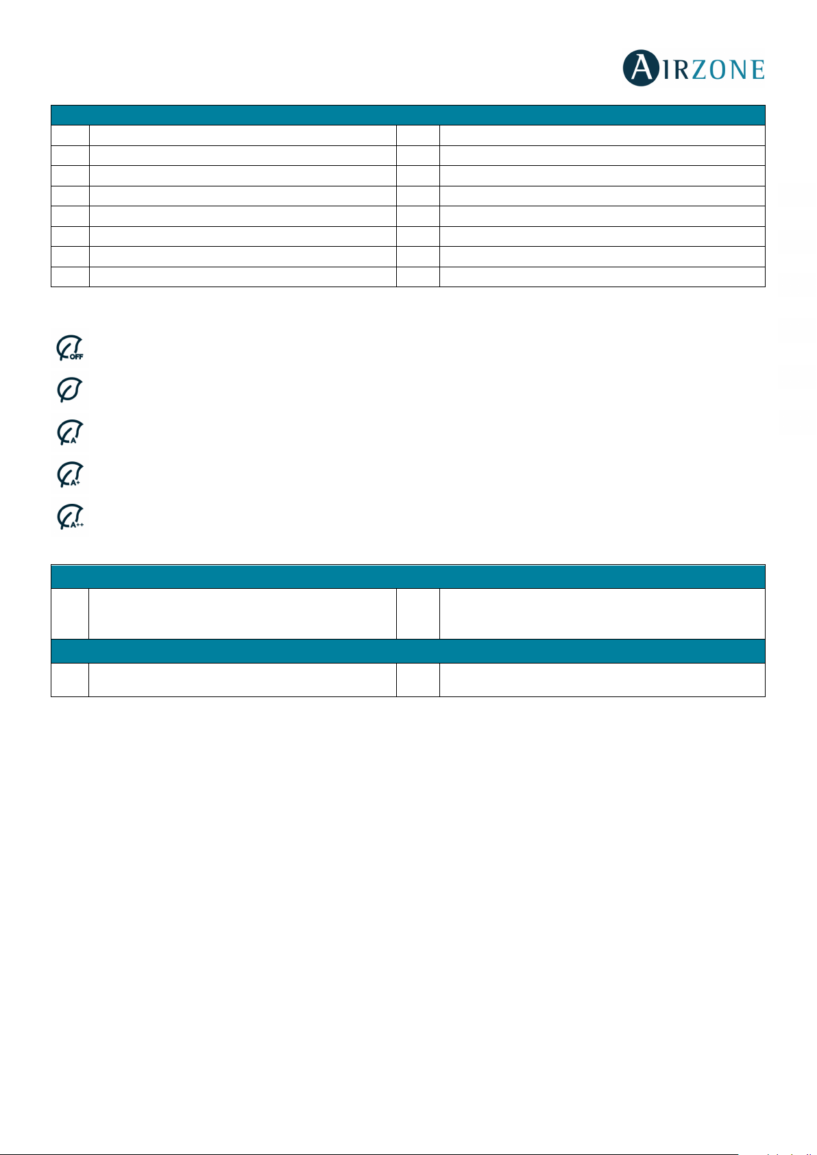
Analog-value
0 à Stop
3 à Heating
4 à Dry
0 à Stop
1 à Speed 1
2 à Speed 2
3 à Speed 3
0 Z1 Set point R/W 15-30 °C*
1 Z2 Set point R/W 15-30 °C*
2 Z3 Set point R/W 15-30 °C*
3 Z4 Set point R/W 15-30 °C*
4 Z5 Set point R/W 15-30 °C*
5 Z6 Set point R/W 15-30 °C*
6 Z7 Set point R/W 15-30 °C*
7 Z8 Set point R/W 15-30 °C*
ES
EN
FR
*Allowed values may be limited based on the selected Eco-Adapt of the Airzone system:
Cooling: 18-30 °C. Heating: 15-30 °C.
Cooling: 18-30 °C. Heating: 15-30 °C.
Cooling: 24-30 °C. Heating: 15-22 °C.
Cooling: 25-30 °C. Heating: 15-21,5 °C.
Cooling: 26-30 °C. Heating: 15-21 °C.
Multi-state-output
0 ZS Operation mode () R/W
Multi- state-value
0 ZS Fancoil speed () R/W
2 à Cooling
IT
PT
DE
6 à Ventilation
10
Page 11

0 à Deactivated
1 à Activated
0 à Deactivated
1 à Activated
0 à Deactivated
1 à Activated
0 à Deactivated
1 à Activated
0 à Deactivated
1 à Activated
0 à Deactivated
1 à Activated
0 à Deactivated
1 à Activated
0 à Deactivated
1 à Activated
0 à Deactivated
1 à Activated
0 à Deactivated
1 à Activated
0 à Deactivated
1 à Activated
0 à Deactivated
1 à Activated
0 à Deactivated
1 à Activated
0 à Deactivated
1 à Activated
0 à Deactivated
1 à Activated
0 à Deactivated
1 à Activated
0 à Deactivated
1 à Activated
0 à Deactivated
1 à Activated
0 à Deactivated
1 à Activated
0 à Deactivated
1 à Activated
0 à Deactivated
1 à Activated
0 à Deactivated
1 à Activated
0 à Deactivated
1 à Activated
0 à Deactivated
1 à Activated
0 à Deactivated
1 à Activated
0 à Deactivated
1 à Activated
0 à Deactivated
1 à Activated
0 à Deactivated
1 à Activated
0 à Deactivated
1 à Activated
0 à Deactivated
1 à Activated
0 à Deactivated
1 à Activated
0 à Deactivated
1 à Activated
0 à Deactivated
1 à Activated
0 à Deactivated
1 à Activated
0 à Deactivated
1 à Activated
0 à Deactivated
1 à Activated
0 à Deactivated
1 à Activated
0 à Deactivated
1 à Activated
0 à Deactivated
1 à Activated
0 à Deactivated
1 à Activated
0 à Deactivated
1 à Activated
0 à Deactivated
1 à Activated
0 à Deactivated
1 à Activated
0 à Deactivated
1 à Activated
0 à Deactivated
1 à Activated
0 à Deactivated
1 à Activated
0 à Deactivated
1 à Activated
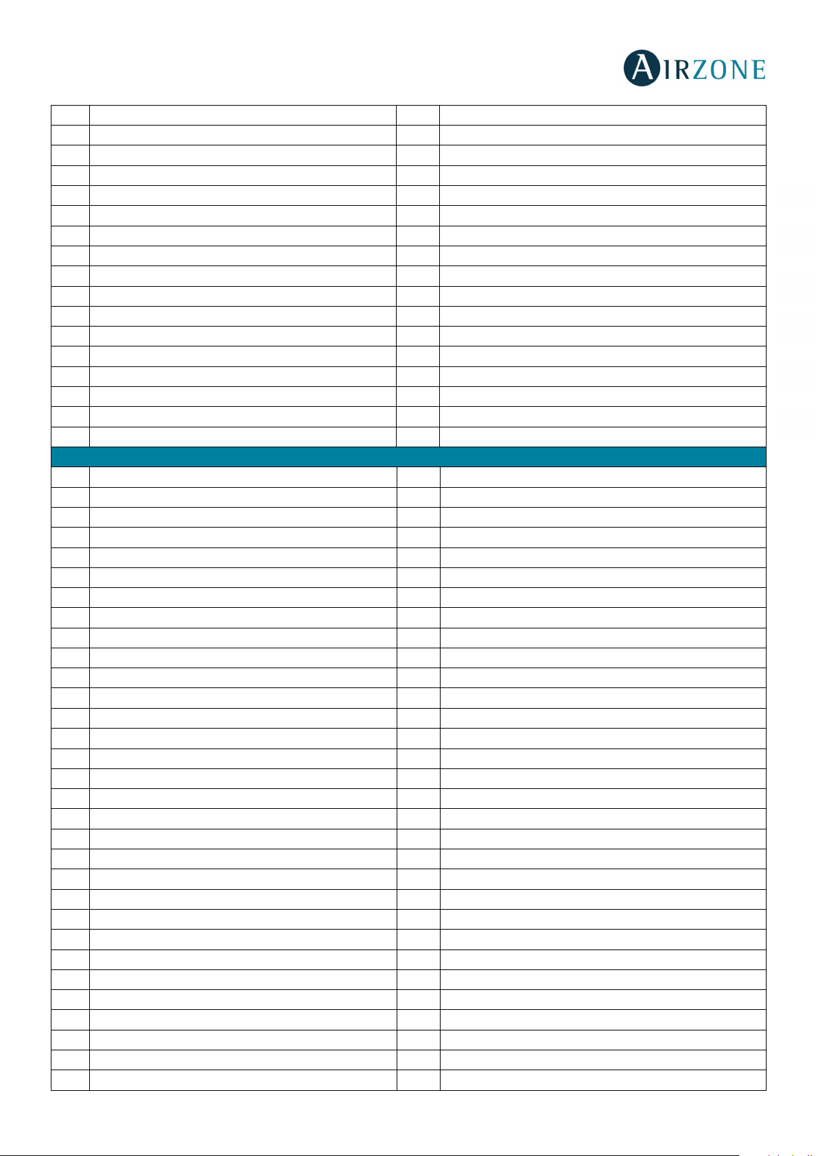
Acuazone / Innobus Pro32 Systems
0 Z1 Window alert R
1 Z1 Presence alert R
2 Z2 Window alert R
3 Z2 Presence alert R
4 Z3 Window alert R
5 Z3 Presence alert R
6 Z4 Window alert R
7 Z4 Presence alert R
8 Z5 Window alert R
9 Z5 Presence alert R
10 Z6 Window alert R
11 Z6 Presence alert R
12 Z7 Window alert R
13 Z7 Presence alert R
14 Z8 Window alert R
15 Z8 Presence alert R
16 Z9 Window alert R
17 Z9 Presence alert R
18 Z10 Window alert R
19 Z10 Presence alert R
20 Z11 Window alert R
21 Z11 Presence alert R
22 Z12 Window alert R
23 Z12 Presence alert R
24 Z13 Window alert R
25 Z13 Presence alert R
26 Z14 Window alert R
27 Z14 Presence alert R
28 Z15 Window alert R
29 Z15 Presence alert R
30 Z16 Window alert R
31 Z16 Presence alert R
32 Z17 Window alert R
33 Z17 Presence alert R
34 Z18 Window alert R
35 Z18 Presence alert R
36 Z19 Window alert R
37 Z19 Presence alert R
38 Z20 Window alert R
39 Z20 Presence alert R
40 Z21 Window alert R
41 Z21 Presence alert R
42 Z22 Window alert R
43 Z22 Presence alert R
44 Z23 Window alert R
45 Z23 Presence alert R
46 Z24 Window alert R
Binary-input
ES
EN
FR
IT
PT
DE
11
Page 12
0 à Deactivated
1 à Activated
0 à Deactivated
1 à Activated
0 à Deactivated
1 à Activated
0 à Deactivated
1 à Activated
0 à Deactivated
1 à Activated
0 à Deactivated
1 à Activated
0 à Deactivated
1 à Activated
0 à Deactivated
1 à Activated
0 à Deactivated
1 à Activated
0 à Deactivated
1 à Activated
0 à Deactivated
1 à Activated
0 à Deactivated
1 à Activated
0 à Deactivated
1 à Activated
0 à Deactivated
1 à Activated
0 à Deactivated
1 à Activated
0 à Deactivated
1 à Activated
0 à Deactivated
1 à Activated
Binary-output
0 à Off
1 à On
0 à Off
1 à On
0 à Off
1 à On
0 à Off
1 à On
0 à Off
1 à On
0 à Off
1 à On
0 à Off
1 à On
0 à Off
1 à On
0 à Off
1 à On
0 à Off
1 à On
0 à Off
1 à On
0 à Off
1 à On
0 à Off
1 à On
0 à Off
1 à On
0 à Off
1 à On
0 à Off
1 à On
0 à Off
1 à On
0 à Off
1 à On
0 à Off
1 à On
0 à Off
1 à On
0 à Off
1 à On
0 à Off
1 à On
0 à Off
1 à On
0 à Off
1 à On
0 à Off
1 à On
0 à Off
1 à On
0 à Off
1 à On
0 à Off
1 à On
0 à Off
1 à On
0 à Off
1 à On
0 à Off
1 à On
47 Z24 Presence alert R
48 Z25 Window alert R
49 Z25 Presence alert R
50 Z26 Window alert R
51 Z26 Presence alert R
52 Z27 Window alert R
53 Z27 Presence alert R
54 Z28 Window alert R
55 Z28 Presence alert R
56 Z29 Window alert R
57 Z29 Presence alert R
58 Z30 Window alert R
59 Z30 Presence alert R
60 Z31 Window alert R
61 Z31 Presence alert R
62 Z32 Window alert R
63 Z32 Presence alert R
0 Z1 Radiant On/Off R
1 Z2 Radiant On/Off R
2 Z3 Radiant On/Off R
3 Z4 Radiant On/Off R
4 Z5 Radiant On/Off R
5 Z6 Radiant On/Off R
6 Z7 Radiant On/Off R
7 Z8 Radiant On/Off R
8 Z9 Radiant On/Off R
9 Z10 Radiant On/Off R
10 Z11 Radiant On/Off R
11 Z12 Radiant On/Off R
12 Z13 Radiant On/Off R
13 Z14 Radiant On/Off R
14 Z15 Radiant On/Off R
15 Z16 Radiant On/Off R
16 Z17 Radiant On/Off R
17 Z18 Radiant On/Off R
18 Z19 Radiant On/Off R
19 Z20 Radiant On/Off R
20 Z21 Radiant On/Off R
21 Z22 Radiant On/Off R
22 Z23 Radiant On/Off R
23 Z24 Radiant On/Off R
24 Z25 Radiant On/Off R
25 Z26 Radiant On/Off R
26 Z27 Radiant On/Off R
27 Z28 Radiant On/Off R
28 Z29 Radiant On/Off R
29 Z30 Radiant On/Off R
30 Z31 Radiant On/Off R
ES
EN
FR
IT
PT
DE
12
Page 13
0 à Off
1 à On
0 à Deactivated
1 à Activated
0 à Deactivated
1 à Activated
0 à Deactivated
1 à Activated
0 à Deactivated
1 à Activated
0 à Off
1 à On
0 à Off
1 à On
0 à Off
1 à On
0 à Off
1 à On
0 à Off
1 à On
0 à Off
1 à On
0 à Off
1 à On
0 à Off
1 à On
0 à Off
1 à On
0 à Off
1 à On
0 à Off
1 à On
0 à Off
1 à On
0 à Off
1 à On
0 à Off
1 à On
0 à Off
1 à On
0 à Off
1 à On
0 à Off
1 à On
0 à Off
1 à On
0 à Off
1 à On
0 à Off
1 à On
0 à Off
1 à On
0 à Off
1 à On
0 à Off
1 à On
0 à Off
1 à On
0 à Off
1 à On
0 à Off
1 à On
0 à Off
1 à On
0 à Off
1 à On
0 à Off
1 à On
0 à Off
1 à On
0 à Off
1 à On
0 à Off
1 à On
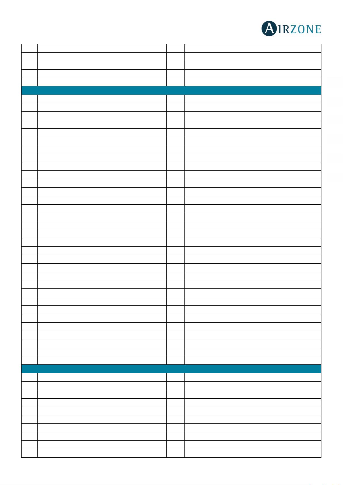
31 Z32 Radiant On/Off R
32 Cooling air demand R
33 Heating air demand R
34 Cooling radiant demand R
35 Heating radiant demand R
Binary-value
0 Z1 On/Off R/W
1 Z2 On/Off R/W
2 Z3 On/Off R/W
3 Z4 On/Off R/W
4 Z5 On/Off R/W
5 Z6 On/Off R/W
6 Z7 On/Off R/W
7 Z8 On/Off R/W
8 Z9 On/Off R/W
9 Z10 On/Off R/W
10 Z11 On/Off R/W
11 Z12 On/Off R/W
12 Z13 On/Off R/W
13 Z14 On/Off R/W
14 Z15 On/Off R/W
15 Z16 On/Off R/W
16 Z17 On/Off R/W
17 Z18 On/Off R/W
18 Z19 On/Off R/W
19 Z20 On/Off R/W
20 Z21 On/Off R/W
21 Z22 On/Off R/W
22 Z23 On/Off R/W
23 Z24 On/Off R/W
24 Z25 On/Off R/W
25 Z26 On/Off R/W
26 Z27 On/Off R/W
27 Z28 On/Off R/W
28 Z29 On/Off R/W
29 Z30 On/Off R/W
30 Z31 On/Off R/W
31 Z32 On/Off R/W
Analog-input
0 Z1 Ambient temperature R 10 -35 °C
1 Z1 Humidity R 0 -100
2 Z2 Ambient temperature R 10 -35 °C
3 Z2 Humidity R 0 -100
4 Z3 Ambient temperature R 10 -35 °C
5 Z3 Humidity R 0 -100
6 Z4 Ambient temperature R 10 -35 °C
7 Z4 Humidity R 0 -100
8 Z5 Ambient temperature R 10 -35 °C
9 Z5 Humidity R 0 -100
ES
EN
FR
IT
PT
DE
13
Page 14

10 Z6 Ambient temperature R 10 -35 °C
11 Z6 Humidity R 0 -100
12 Z7 Ambient temperature R 10 -35 °C
13 Z7 Humidity R 0 -100
14 Z8 Ambient temperature R 10 -35 °C
15 Z8 Humidity R 0 -100
16 Z9 Ambient temperature R 10 -35 °C
17 Z9 Humidity R 0 -100
18 Z10 Ambient temperature R 10 -35 °C
19 Z10 Humidity R 0 -100
20 Z11 Ambient temperature R 10 -35 °C
21 Z11 Humidity R 0 -100
22 Z12 Ambient temperature R 10 -35 °C
23 Z12 Humidity R 0 -100
24 Z13 Ambient temperature R 10 -35 °C
25 Z13 Humidity R 0 -100
26 Z14 Ambient temperature R 10 -35 °C
27 Z14 Humidity R 0 -100
28 Z15 Ambient temperature R 10 -35 °C
29 Z15 Humidity R 0 -100
30 Z16 Ambient temperature R 10 -35 °C
31 Z16 Humidity R 0 -100
32 Z17 Ambient temperature R 10 -35 °C
33 Z17 Humidity R 0 -100
34 Z18 Ambient temperature R 10 -35 °C
35 Z18 Humidity R 0 -100
36 Z19 Ambient temperature R 10 -35 °C
37 Z19 Humidity R 0 -100
38 Z20 Ambient temperature R 10 -35 °C
39 Z20 Humidity R 0 -100
40 Z21 Ambient temperature R 10 -35 °C
41 Z21 Humidity R 0 -100
42 Z22 Ambient temperature R 10 -35 °C
43 Z22 Humidity R 0 -100
44 Z23 Ambient temperature R 10 -35 °C
45 Z23 Humidity R 0 -100
46 Z24 Ambient temperature R 10 -35 °C
47 Z24 Humidity R 0 -100
48 Z25 Ambient temperature R 10 -35 °C
49 Z25 Humidity R 0 -100
50 Z26 Ambient temperature R 10 -35 °C
51 Z26 Humidity R 0 -100
52 Z27 Ambient temperature R 10 -35 °C
53 Z27 Humidity R 0 -100
54 Z28 Ambient temperature R 10 -35 °C
55 Z28 Humidity R 0 -100
56 Z29 Ambient temperature R 10 -35 °C
57 Z29 Humidity R 0 -100
58 Z30 Ambient temperature R 10 -35 °C
ES
EN
FR
IT
PT
DE
14
Page 15
59 Z30 Humidity R 0 -100
60 Z31 Ambient temperature R 10 -35 °C
61 Z31 Humidity R 0 -100
62 Z32 Ambient temperature R 10 -35 °C
63 Z32 Humidity R 0 -100
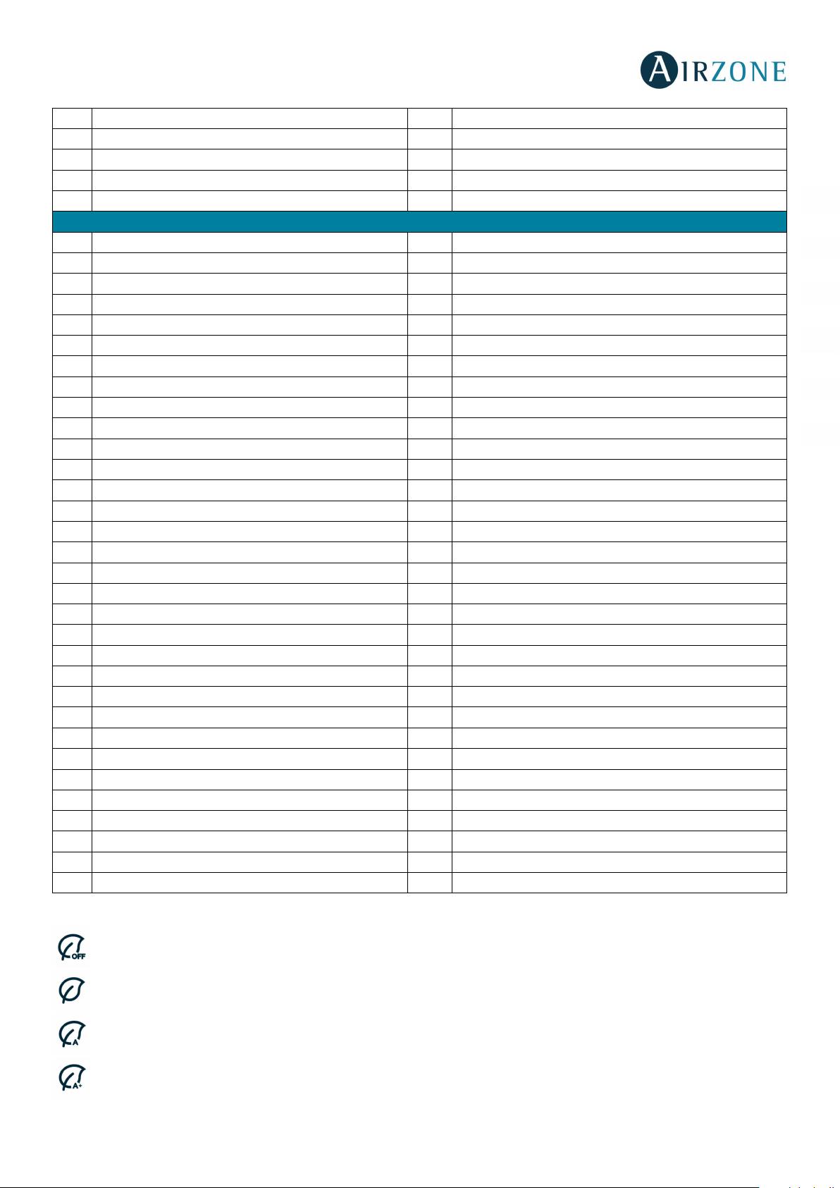
Analog-value
0 Z1 Set point R/W 15-30 °C
1 Z2 Set point R/W 15-30 °C
2 Z3 Set point R/W 15-30 °C
3 Z4 Set point R/W 15-30 °C
4 Z5 Set point R/W 15-30 °C
5 Z6 Set point R/W 15-30 °C
6 Z7 Set point R/W 15-30 °C
7 Z8 Set point R/W 15-30 °C
8 Z9 Set point R/W 15-30 °C
9 Z10 Set point R/W 15-30 °C
10 Z11 Set point R/W 15-30 °C
11 Z12 Set point R/W 15-30 °C
12 Z13 Set point R/W 15-30 °C
13 Z14 Set point R/W 15-30 °C
14 Z15 Set point R/W 15-30 °C
15 Z16 Set point R/W 15-30 °C
16 Z17 Set point R/W 15-30 °C
17 Z18 Set point R/W 15-30 °C
18 Z19 Set point R/W 15-30 °C
19 Z20 Set point R/W 15-30 °C
20 Z21 Set point R/W 15-30 °C
21 Z22 Set point R/W 15-30 °C
22 Z23 Set point R/W 15-30 °C
23 Z24 Set point R/W 15-30 °C
24 Z25 Set point R/W 15-30 °C
25 Z26 Set point R/W 15-30 °C
26 Z27 Set point R/W 15-30 °C
27 Z28 Set point R/W 15-30 °C
28 Z29 Set point R/W 15-30 °C
29 Z30 Set point R/W 15-30 °C
30 Z31 Set point R/W 15-30 °C
31 Z32 Set point R/W 15-30 °C
*Allowed values may be limited based on the selected Eco-Adapt of the Airzone system:
ES
EN
FR
IT
PT
DE
Cooling: 18-30 °C. Heating: 15-30 °C.
Cooling: 18-30 °C. Heating: 15-30 °C.
Cooling: 24-30 °C. Heating: 15-22 °C.
Cooling: 25-30 °C. Heating: 15-21,5 °C.
15
Page 16
0 à Stop
3 à Heating
4 à Dry
0 à Stop
3 à Heating
4 à Dry
0 à Stop
3 à Heating
4 à Dry
0 à Stop
3 à Heating
4 à Dry
0 à Stop
3 à Heating
4 à Dry
0 à Stop
3 à Heating
4 à Dry
0 à Stop
3 à Heating
4 à Dry
0 à Stop
3 à Heating
4 à Dry
0 à Stop
3 à Heating
4 à Dry
0 à Stop
3 à Heating
4 à Dry
0 à Stop
3 à Heating
4 à Dry
0 à Stop
3 à Heating
4 à Dry
0 à Stop
3 à Heating
4 à Dry
0 à Stop
3 à Heating
4 à Dry
0 à Stop
3 à Heating
4 à Dry
0 à Stop
3 à Heating
4 à Dry
0 à Stop
3 à Heating
4 à Dry
Cooling: 26-30 °C. Heating: 15-21 °C.
Multi-state-output
0 ZS Operation mode R/W
1 Z1 Operation mode R/W
2 Z2 Operation mode R/W
3 Z3 Operation mode R/W
4 Z4 Operation mode R/W
5 Z5 Operation mode R/W
6 Z6 Operation mode R/W
7 Z7 Operation mode R/W
2 à Cooling
2 à Cooling
2 à Cooling
2 à Cooling
2 à Cooling
2 à Cooling
2 à Cooling
2 à Cooling
6 à Ventilation
6 à Ventilation
6 à Ventilation
6 à Ventilation
6 à Ventilation
6 à Ventilation
6 à Ventilation
6 à Ventilation
ES
EN
FR
IT
PT
DE
8 Z8 Operation mode R/W
9 Z9 Operation mode R/W
10 Z10 Operation mode R/W
11 Z11 Operation mode R/W
12 Z12 Operation mode R/W
13 Z13 Operation mode R/W
14 Z14 Operation mode R/W
15 Z15 Operation mode R/W
2 à Cooling
2 à Cooling
2 à Cooling
2 à Cooling
2 à Cooling
2 à Cooling
2 à Cooling
2 à Cooling
6 à Ventilation
6 à Ventilation
6 à Ventilation
6 à Ventilation
6 à Ventilation
6 à Ventilation
6 à Ventilation
6 à Ventilation
16 Z16 Operation mode R/W
2 à Cooling
6 à Ventilation
16
Page 17
0 à Stop
3 à Heating
4 à Dry
0 à Stop
3 à Heating
4 à Dry
0 à Stop
3 à Heating
4 à Dry
0 à Stop
3 à Heating
4 à Dry
0 à Stop
3 à Heating
4 à Dry
0 à Stop
3 à Heating
4 à Dry
0 à Stop
3 à Heating
4 à Dry
0 à Stop
3 à Heating
4 à Dry
0 à Stop
3 à Heating
4 à Dry
0 à Stop
3 à Heating
4 à Dry
0 à Stop
3 à Heating
4 à Dry
0 à Stop
3 à Heating
4 à Dry
0 à Stop
3 à Heating
4 à Dry
0 à Stop
3 à Heating
4 à Dry
0 à Stop
3 à Heating
4 à Dry
0 à Stop
3 à Heating
4 à Dry
0 à Stop
1 à Speed 1
2 à Speed 2
3 à Speed 3
0 à Stop
2 à Speed 2
0 à Stop
1 à Speed 1
2 à Speed 2
3 à Speed 3
0 à Stop
1 à Speed 1
2 à Speed 2
3 à Speed 3
17 Z17 Operation mode R/W
18 Z18 Operation mode R/W
19 Z19 Operation mode R/W
20 Z20 Operation mode R/W
21 Z21 Operation mode R/W
22 Z22 Operation mode R/W
23 Z23 Operation mode R/W
24 Z24 Operation mode R/W
2 à Cooling
2 à Cooling
2 à Cooling
2 à Cooling
2 à Cooling
2 à Cooling
2 à Cooling
2 à Cooling
6 à Ventilation
6 à Ventilation
6 à Ventilation
6 à Ventilation
6 à Ventilation
6 à Ventilation
6 à Ventilation
6 à Ventilation
ES
EN
FR
IT
PT
DE
25 Z25 Operation mode R/W
26 Z26 Operation mode R/W
27 Z27 Operation mode R/W
28 Z28 Operation mode R/W
29 Z29 Operation mode R/W
30 Z30 Operation mode R/W
31 Z31 Operation mode R/W
32 Z32 Operation mode R/W
Multi-state-value
2 à Cooling
2 à Cooling
2 à Cooling
2 à Cooling
2 à Cooling
2 à Cooling
2 à Cooling
2 à Cooling
6 à Ventilation
6 à Ventilation
6 à Ventilation
6 à Ventilation
6 à Ventilation
6 à Ventilation
6 à Ventilation
6 à Ventilation
0 ZS Fancoil speed R/W
1 Z1 Fancoil speed R/W
2 Z2 Fancoil speed R/W
3 Z3 Fancoil speed R/W
1 à Speed 1
3 à Speed 3
17
Page 18

0 à Stop
2 à Speed 2
0 à Stop
1 à Speed 1
2 à Speed 2
3 à Speed 3
0 à Stop
1 à Speed 1
2 à Speed 2
3 à Speed 3
0 à Stop
1 à Speed 1
2 à Speed 2
3 à Speed 3
0 à Stop
1 à Speed 1
2 à Speed 2
3 à Speed 3
0 à Stop
1 à Speed 1
2 à Speed 2
3 à Speed 3
0 à Stop
1 à Speed 1
2 à Speed 2
3 à Speed 3
0 à Stop
1 à Speed 1
2 à Speed 2
3 à Speed 3
0 à Stop
1 à Speed 1
2 à Speed 2
3 à Speed 3
0 à Stop
1 à Speed 1
2 à Speed 2
3 à Speed 3
0 à Stop
1 à Speed 1
2 à Speed 2
3 à Speed 3
0 à Stop
2 à Speed 2
0 à Stop
1 à Speed 1
2 à Speed 2
3 à Speed 3
0 à Stop
1 à Speed 1
2 à Speed 2
3 à Speed 3
0 à Stop
1 à Speed 1
2 à Speed 2
3 à Speed 3
0 à Stop
1 à Speed 1
2 à Speed 2
3 à Speed 3
0 à Stop
1 à Speed 1
2 à Speed 2
3 à Speed 3
0 à Stop
1 à Speed 1
2 à Speed 2
3 à Speed 3
0 à Stop
1 à Speed 1
2 à Speed 2
3 à Speed 3
0 à Stop
1 à Speed 1
2 à Speed 2
3 à Speed 3
0 à Stop
1 à Speed 1
2 à Speed 2
3 à Speed 3
0 à Stop
1 à Speed 1
2 à Speed 2
3 à Speed 3
0 à Stop
2 à Speed 2
0 à Stop
1 à Speed 1
2 à Speed 2
3 à Speed 3
0 à Stop
2 à Speed 2
0 à Stop
1 à Speed 1
2 à Speed 2
3 à Speed 3
0 à Stop
1 à Speed 1
2 à Speed 2
3 à Speed 3
0 à Stop
1 à Speed 1
2 à Speed 2
3 à Speed 3
0 à Stop
1 à Speed 1
2 à Speed 2
3 à Speed 3
4 Z4 Fancoil speed R/W
5 Z5 Fancoil speed R/W
6 Z6 Fancoil speed R/W
7 Z7 Fancoil speed R/W
8 Z8 Fancoil speed R/W
9 Z9 Fancoil speed R/W
10 Z10 Fancoil speed R/W
11 Z11 Fancoil speed R/W
12 Z12 Fancoil speed R/W
13 Z13 Fancoil speed R/W
14 Z14 Fancoil speed R/W
15 Z15 Fancoil speed R/W
1 à Speed 1
1 à Speed 1
3 à Speed 3
ES
EN
FR
IT
PT
DE
3 à Speed 3
16 Z16 Fancoil speed R/W
17 Z17 Fancoil speed R/W
18 Z18 Fancoil speed R/W
19 Z19 Fancoil speed R/W
20 Z20 Fancoil speed R/W
21 Z21 Fancoil speed R/W
22 Z22 Fancoil speed R/W
23 Z23 Fancoil speed R/W
24 Z24 Fancoil speed R/W
25 Z25 Fancoil speed R/W
26 Z26 Fancoil speed R/W
27 Z27 Fancoil speed R/W
1 à Speed 1
3 à Speed 3
28 Z28 Fancoil speed R/W
29 Z29 Fancoil speed R/W
30 Z30 Fancoil speed R/W
31 Z31 Fancoil speed R/W
32 Z32 Fancoil speed R/W
1 à Speed 1
3 à Speed 3
18
Page 19

DETAILED DESCRIPTION OF THE OBJECTS
COMMON TO ALL OBJECTS
For each Airzone system:
1. When the indoor unit is communicating normally, a communication can be established between the Airzone BACnet
Interface and the indoor unit. The BACnet building management system will then have access to the Airzone unit’s
objects.
2. If the communication between the Airzone BACnet Interface and the system is not correct, or if a request for
information related to a communication object that is not present in the Airzone system the object's property "Out of
service" is activated.
Z# ALARM INPUT
ES
EN
FR
IT
This object represents the state of alarm input available to the Airzone main board (normally closed contact), indicating
whether this input is active or inactive. When this input is active, the system remains in STOP. This is a Read only object.
Z# RADIANT STAGE
This object displays if the radiant stage is activated or deactivated in each zone. This is a Read only object.
Important: the following combinations will not generate air:
- Airzone-xxx Gateway Communication (AZX6QADAPTxxx) on Flexa 3.0, Innobus Pro6, Acuazone and Innobus Pro32
main control boards.
- Airzone-Electromechanical Unit Control Gateway (AZX6ELECTROMEC) on Flexa 3.0, Innobus Pro6, Acuazone and
Innobus Pro32 main control boards.
- Wired/wireless individual unit infrared zone module (AZDI6MCIFR [C/R]) on Acuazone and Innobus Pro32 systems
configured as zoning system or mixed.
- Wired/wireless individual unit zone module xxx (AZDI6MCxxx [C/R]) on Acuazone and Innobus Pro32 systems
configured as zoning system or mixed.
Important: the following combinations will not generate radiant demand:
- Wired/wireless zoning module for electrical heating element (AZDI6MZSRE [C/R] on Acuazone and Innobus Pro32.
AIR/RADIANT DEMAND
PT
DE
This object displays if there is cooling or heating demand in air or radiant stage. This is a Read only object.
Z# ON/OFF
The Airzone BACnet Interface will report the status of each zone. Using the BACnet platform, any zone may be configured as
on/off. These are Read/Write objects.
Z# ROOM TEMPERATURE
The BACnet platform can obtain the actual room temperature for any zone. These are read only objects.
Z# HUMIDITY
The BACnet platform can obtain the actual humidity for each zone. These are read only objects.
19
Page 20

Z# SET POINT
Each thermostat can be configured for a determined set point, and those values are reported to the BACnet platform, and can
be changed from it. These are Read/Write objects.
Allowed values may be limited based on the selected Eco-Adapt of the Airzone system:
Cooling: 18-30 °C. Heating: 15-30 °C.
Cooling: 18-30 °C. Heating: 15-30 °C.
Cooling: 24-30 °C. Heating: 15-22 °C.
Cooling: 25-30 °C. Heating: 15-21,5 °C.
Cooling: 26-30 °C. Heating: 15-21 °C.
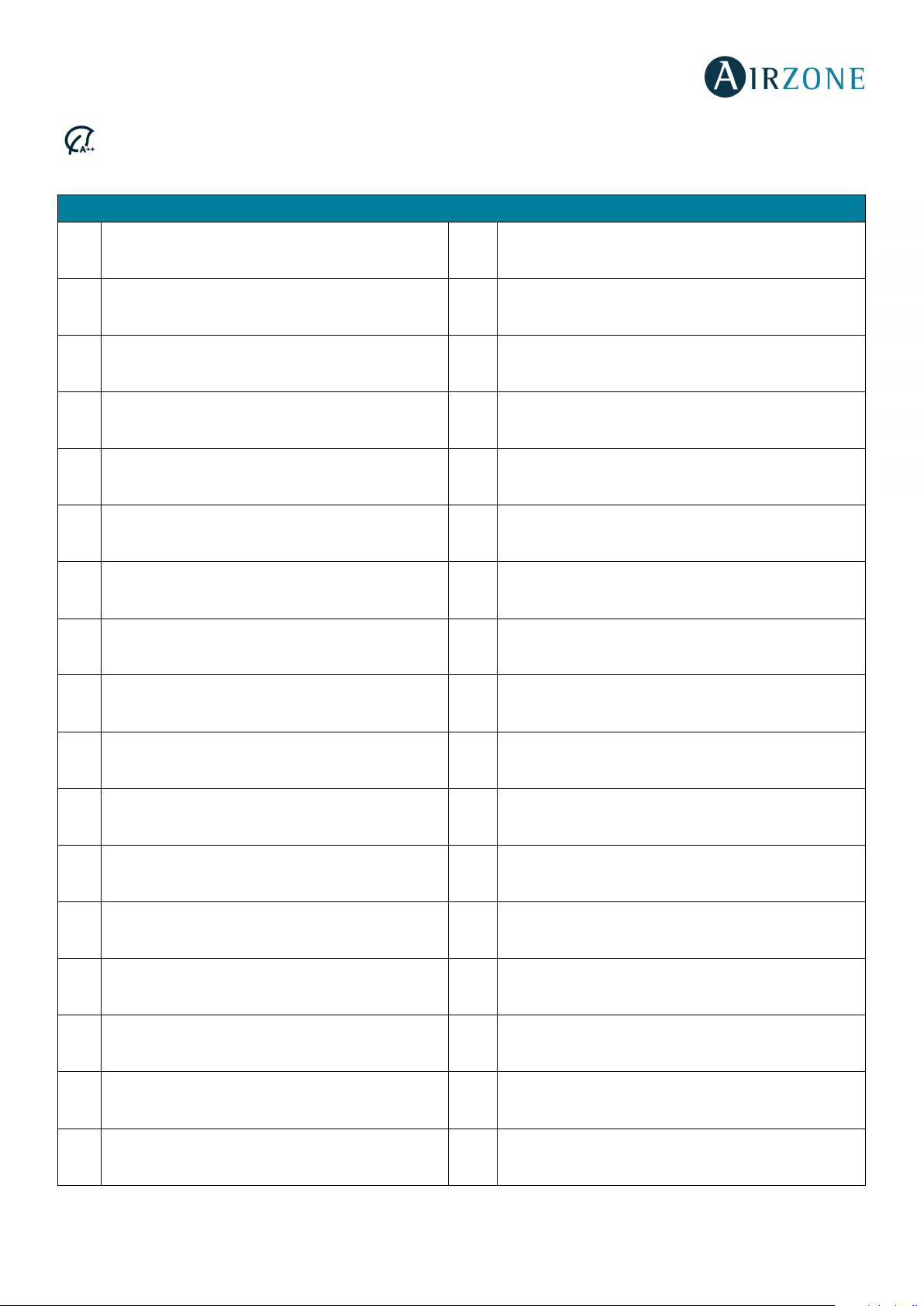
Z# OPERATION MODE
The Airzone BACnet Interface will report the operation mode of the system or the operation mode of each zone (depending on
the connected system), represented by a number. These are Read/Write objects. These modes are:
0 à Stop
2 à Cooling
3 à Heating
ES
EN
FR
IT
PT
DE
4 à Dry
6 à Ventilation
In VRV Heat Pump installations, all the indoor units must work in supported/compatible operation modes, the operation mode
of the Airzone connected to a slave indoor unit could be restricted or limited by the operation mode selected in the Airzone
connected to the master indoor unit.
If in the same VRV Heat Pump installation, an Airzone unit is connected to a slave indoor unit and another indoor unit is
configured as the master (with or without Airzone connected to):
- When the master IU is operating in Fan mode, the Airzone system will send the current mode (cool, heat or dry) to the
BACnet interface, if a cooling or heating demand exits.
- If no cooling or heating demand exits, the Airzone system will report STOP to the BACnet Interface.
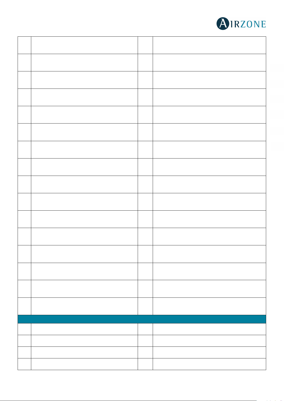
Z# FANCOIL SPEED
This parameter refers to the Fancoil Unit fan speed. The Airzone BACnet Interface will report the system speed of each zone
(depending on the connected system), represented by a number. These are Read/Write objects:
0 à Stop
1 à Speed 1
2 à Speed 2
3 à Speed 3
20
Page 21
TROUBLESHOOTING
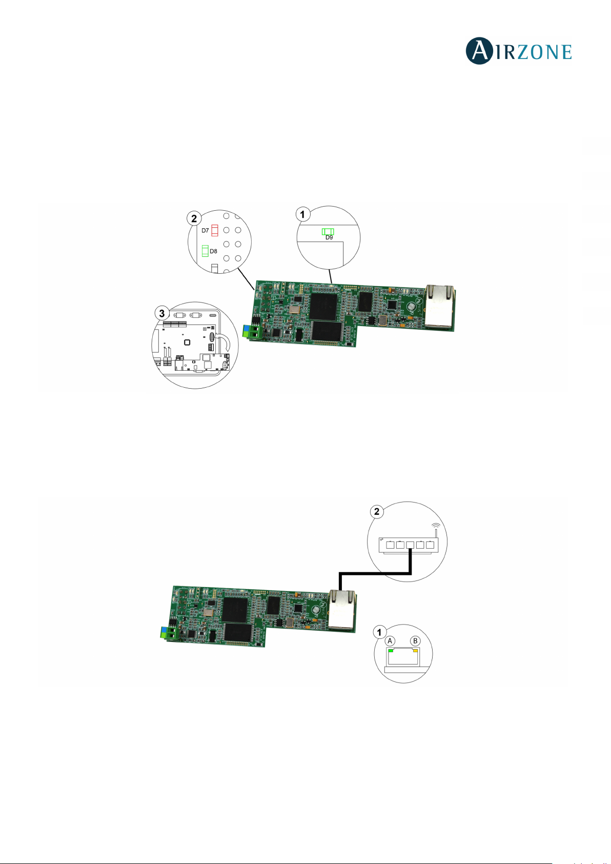
THE AIRZONE SYSTEM DOES NOT DETECT THE AIRZONE BACNET INTERFACE
Verify the following items:
1. The D9 LED (Microswitch performance) is blinking.
2. The D7 and D8 LEDs are alternately blinking.
3. The correct connection between the Airzone BACnet Interface in the Airzone main control board.
ES
EN
FR
IT
PT
DE
THE AIRZONE BACNET INTERFACE CANNOT BE CONNECTED (I)
Verify the following items:
1. LEDs “A” and “B” are blinking, and those in the Ethernet connector are active.
2. Check that the Ethernet cable is properly connected.
THE AIRZONE BACNET INTERFACE CANNOT BE CONNECTED (II)
Check the following possible causes:
1. Using the Ethernet (LAN)
- Check the state of the LEDs of the Airzone BACnet Interface. If all of them are blinking at the same time, it means the
IP selected for the Airzone BACnet Interface is already being used by another device. Access settings (see section IP
configuration) and change the parameter IP address.
21
Page 22
- Verify that the IP address set for the PC is correct.
- Verify the Ethernet cable connection:
• Verify if connecting via the hub: straight cable.
• Verify communication with the Interface for use in BACnet® by testing the operation from the PC directly: Use a
crossover cable.
- Verify that the PC's LAN communication port is active.
- If using the hub, verify that the hub is powered on.
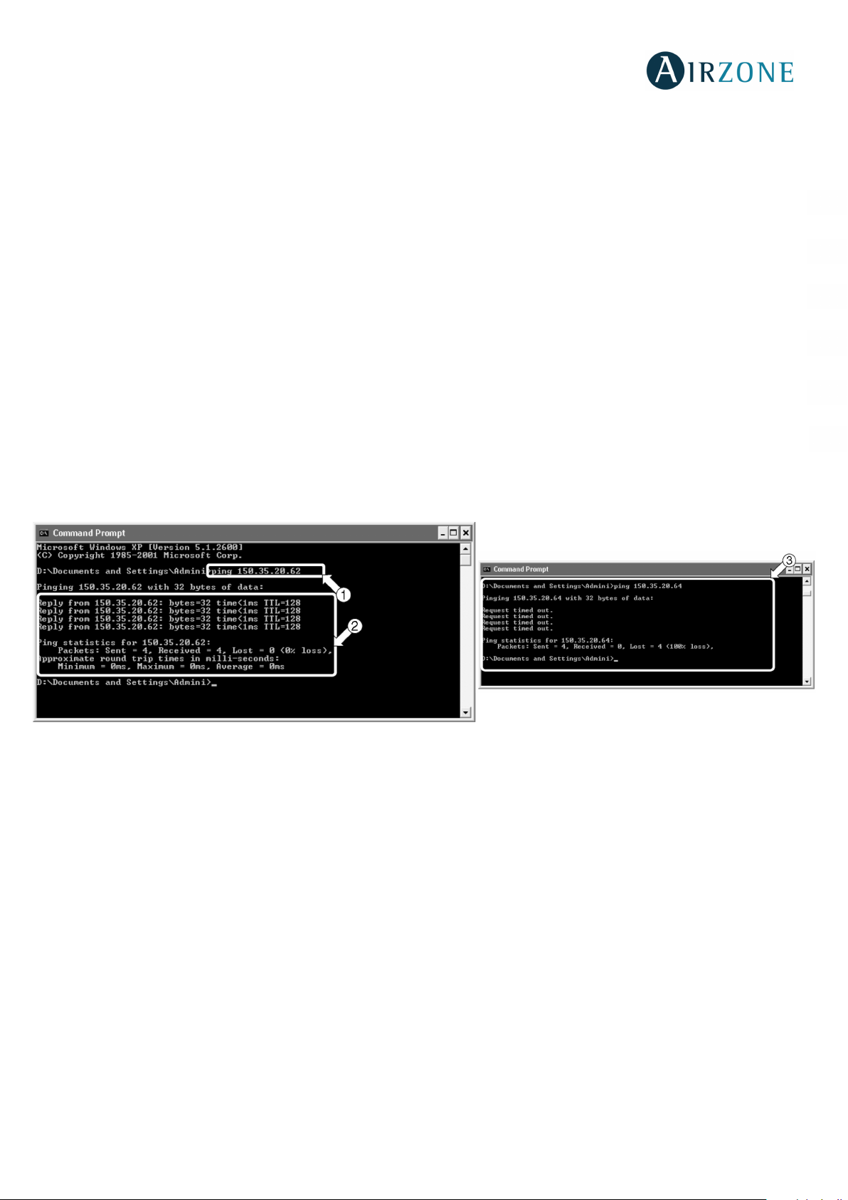
- Do a PING to the Airzone BACnet Interface from the PC to verify the Ethernet Link (See below).
[Cómo ejecutar un PING a la pasarela BACnet].
1. From the PC's desktop, select "Start", "Program", "Accessories", and "Command Prompt". The dialog box shown
below opens.
2. Use the PC's key board; enter the BACnet gateway IP address in [1]. Ex. When Interface for use in BACnet®'s IP
address is "150.35.20.62", enter "ping 150.35.20.62" and press the Return key.
2. If you can see information as shown in [2], the LAN connection is established. Start the test operation program and try
connection again.
If you see information as shown in [3], the LAN connection is not established for some reason. Check the PC's settings, etc.
again.
ES
EN
FR
IT
PT
DE
HOW TO SET THE PC’S IP ADDRESS
1. Take a note of the test operation PC's current IP address. (Be sure to take a note of the current IP address because this
address needs to be restored after the test operation)
1.1. Start the test operation PC. (The screens shown below are Windows XP's examples, and the actual
screens differ depending on the OS used).
1.2. On Windows XP, double-click the Network Connections icon on the Control Panel. Click the Local Area
Connection and right-click to choose "Properties". The dialog box 1 below opens.
1.3. For newer OS, click start and enter “ncpa.cpl” on the search bar to see the network connections window.
Right click over “local area connection” and select “properties”.
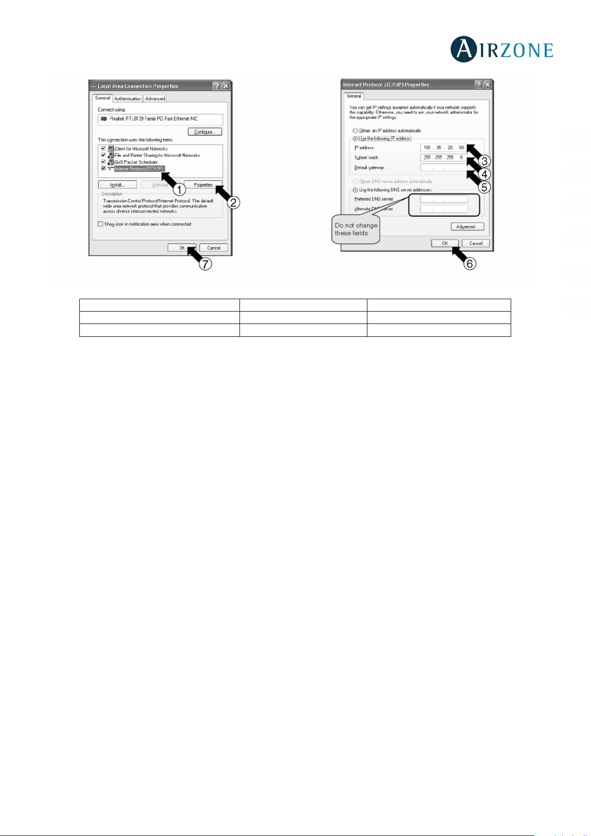
1.4. Select "Internet Protocol (TCP / IP)" [1] and click the Properties button [2]. The dialog box 2 opens. This
dialog box shows the test operation PC's current IP address [3], subnet mask [4], and default gateway
address [5]. Take a note of this information in Table 1.
22
Page 23
[3] IP Address
Ej. 150.35.20.60
[4] Subnet mask
Ej. 255.255.255.0
[5] Default gateway address
Ej. 15.35.20.254
ES
EN
FR
IT
Dialog box 1. Local Area Connection Properties Dialog box 2. Internet Protocol (TCP / IP) Properties
[Table 1: Test Operation PC's Current Address]
2. Change the test operation PC's IP address. Use one of the following IP address depending on the current status of the
Interface for use in BACnet®. If the Interface for use in BACnet®’s IP address has not been changed from the factory
setting, use the following:
- Port: 47808
- IP Address: DHCP
- Subnet Mask: 255.255.255.0
- Gateway IP: 192.168.0.1
If the Interface for use in BACnet®’s IP address has been changed from the factory setting at the site, use the
following:
- IP address shown in the table in "[6]-2. IP address temporarily used for the test service operation" on P.12.
2.1. Enter the information above in "IP address" [3], "subnet mask" [4], and "default gateway" [5] in the dialog
box 2 of Step 1-3, and press the OK button [6]. The dialog box 1 reappears. Click the OK or Cancel button
[7].
PT
DE
2.2. Reboot the PC as required by the PC. (Reboot may not be necessary depending on the Windows version.
3. Return the IP address to the original address after the test operation. (Be sure to return the test operation PC's IP address
to the original address).
3.1. Return the test operation PC's IP address to the original address recorded in Step 1-3, as instructed in
Reboot the PC only when requested).
Steps 2-1 and 2-2.
23
Page 24

Parque Tecnológico de Andalucía
C/ Marie Curie, 21 – 29590
Campanillas – Málaga - España
Teléfono: +34 900 400 445
Fax: +34 902 400 446
Parc Tertiaire Silic – Inmeuble Panama
45 Rue Villeneuve
94573 Rungis - France
Téléphone : +33 184 884 695
Fax : +33 144 042 114
Via Fabio Filzi, 19/E – 20032
Cormano – Milano - Italia
Telefono: +39 02 56814756
Fax: +39 02 56816158
http://www.myzone.airzone.es
http://www.myzone.airzonefrance.fr
http://www.myzone.airzoneitalia.it
 Loading...