

Page 1
I R S T R E A M
A
1 9 9 7
R A I N
G
O N D I T I O N I N G
C
Y S T E M S
S
DRYER OPERATION
A N D S E R V I C E M A N U A L
PNEG-339
1100 SERIES SINGLE FAN
PORTABLE DRYER
MODELS
1
Page 2

2
Page 3

1100 SERIES DRYER OPERATION AND SERVICE
TABLE OF CONTENTS
Warranty.......................................................................................................................4
Safety First...................................................................................................................5
Safety Alert Decals.......................................................................................................6
Safety Precautions.......................................................................................................7
Dryer Control Panel Featuring The Electronic Monitoring Control System.......................8
Safety Circuit Shutdown Messages......................................................................13
Dryer Pre Start Checks...............................................................................................14
Pre Season Inspection..........................................................................................14
Dryer Start Up...................................................................................................................18
Continuous Flow And Continuous Batch Start Up Procedure..............................18
Continuous Flow Metering Roll Settings...............................................................19
Continuous Batch Metering Roll And Timer Settings................................................22
1100 Series Dryer Service Guide.....................................................................................23
Seasonal Inspection And Service.........................................................................24
Suggested Lubricants..........................................................................................25
Fan Propellor Removal And Installation...............................................................26
Fan Motor Removal And Installation....................................................................27
Heater Parts Removal And Installation................................................................28
Metering Roll Servicing........................................................................................29
How To Determine A Metering Roll Problem........................................................30
Wiring Diagrams...................................................................................................31
Trouble Analysis Procedure...................................................................................41
Quick Reference Guide........................................................................................46
Notes...................................................................................................................47
3
Page 4

WARRANTY
THE GSI GROUP, INC. ("GSI") WARRANTS ALL PRODUCTS MANUFACTURED BY GSI TO BE FREE OF
DEFECTS IN MATERIAL AND WORKMANSHIP UNDER NORMAL USAGE AND CONDITIONS FOR A PERIOD OF TWENTY-FOUR MONTHS AFTER RETAIL SALE TO THE ORIGINAL END USER OF SUCH PRODUCTS. GSI'S ONLY OBLIGATION IS, AND PURCHASER'S SOLE REMEDY SHALL BE FOR GSI, TO REPAIR OR REPLACE, AT GSI'S OPTION AND EXPENSE, PRODUCTS THAT, IN GSI'S SOLE JUDGMENT,
CONTAIN A MATERIAL DEFECT DUE TO MATERIALS OR WORKMANSHIP. ALL DELIVERY AND SHIPMENT CHARGES TO AND FROM GSI'S FACTORY WILL BE PURCHASER'S RESPONSIBILITY. EXPENSES
INCURRED BY OR ON BEHALF OF THE PURCHASER WITHOUT PRIOR WRITTEN AUTHORIZATION
FROM AN AUTHORIZED EMPLOYEE OF GSI SHALL BE THE SOLE RESPONSIBILITY OF THE PURCHASER.
EXCEPT FOR THE ABOVE STATED EXPRESS LIMITED WARRANTIES, GSI MAKES NO WARRANTY OF
ANY KIND, EXPRESSED OR IMPLIED, INCLUDING, WITHOUT LIMITATION, WARRANTIES OF MERCHANTABILITY OR FITNESS FOR A PARTICULAR PURPOSE OR USE IN CONNECTION WITH (i) PRODUCT MANUFACTURED OR SOLD BY GSI OR (ii) ANY ADVICE, INSTRUCTION, RECOMMENDATION OR
SUGGESTION PROVIDED BY AN AGENT, REPRESENTATIVE OR EMPLOYEE OF GSI REGARDING OR
RELATED TO THE CONFIGURATION, INSTALLATION, LAYOUT, SUITABILITY FOR A PARTICULAR PURPOSE, OR DESIGN OF SUCH PRODUCT OR PRODUCTS.
IN NO EVENT SHALL GSI BE LIABLE FOR ANY DIRECT, INDIRECT, INCIDENTAL OR CONSEQUENTIAL DAMAGES, INCLUDING, WITHOUT LIMITATION, LOSS OF ANTICIPATED PROFITS OR BENEFITS.
PURCHASER'S SOLE AND EXCLUSIVE REMEDY SHALL BE LIMITED TO THAT STATED ABOVE, WHICH
SHALL NOT EXCEED THE AMOUNT PAID FOR THE PRODUCT PURCHASED. THIS WARRANTY IS NOT
TRANSFERABLE AND APPLIES ONLY TO THE ORIGINAL PURCHASER. GSI SHALL HAVE NO OBLIGATION OR RESPONSIBILITY FOR ANY REPRESENTATIVE OR WARRANTIES MADE BY OR ON BEHALF
OF ANY DEALER, AGENT OR DISTRIBUTOR OF GSI.
GSI ASSUMES NO RESPONSIBILITY FOR FIELD MODIFICATIONS OR ERECTION DEFECTS WHICH
CREATE STRUCTURAL OR STORAGE QUALITY PROBLEMS. MODIFICATIONS TO THE PRODUCT NOT
SPECIFICALLY COVERED BY THE CONTENTS OF THIS MANUAL WILL NULLIFY ANY PRODUCT WARRANTY THAT MIGHT HAVE BEEN OTHERWISE AVAILABLE.
THE FOREGOING WARRANTY SHALL NOT COVER PRODUCTS OR PARTS WHICH HAVE BEEN
DAMAGED BY NEGLIGENT USE, MISUSE, ALTERATION OR ACCIDENT. THIS WARRANTY COVERS
ONLY PRODUCTS MANUFACTURED BY GSI. THIS WARRANTY IS EXCLUSIVE AND IN LIEU OF ALL
OTHER WARRANTIES EXPRESS OR IMPLIED. GSI RESERVES THE RIGHT TO MAKE DESIGN OR SPECIFICATION CHANGES AT ANY TIME.
PRIOR TO INSTALLATION, PURCHASER HAS THE RESPONSIBILITY TO RESEARCH AND COMPLY WITH ALL FEDERAL, STATE AND LOCAL CODES WHICH MAY APPLY TO THE LOCATION AND
INSTALLATION.
4
Page 5
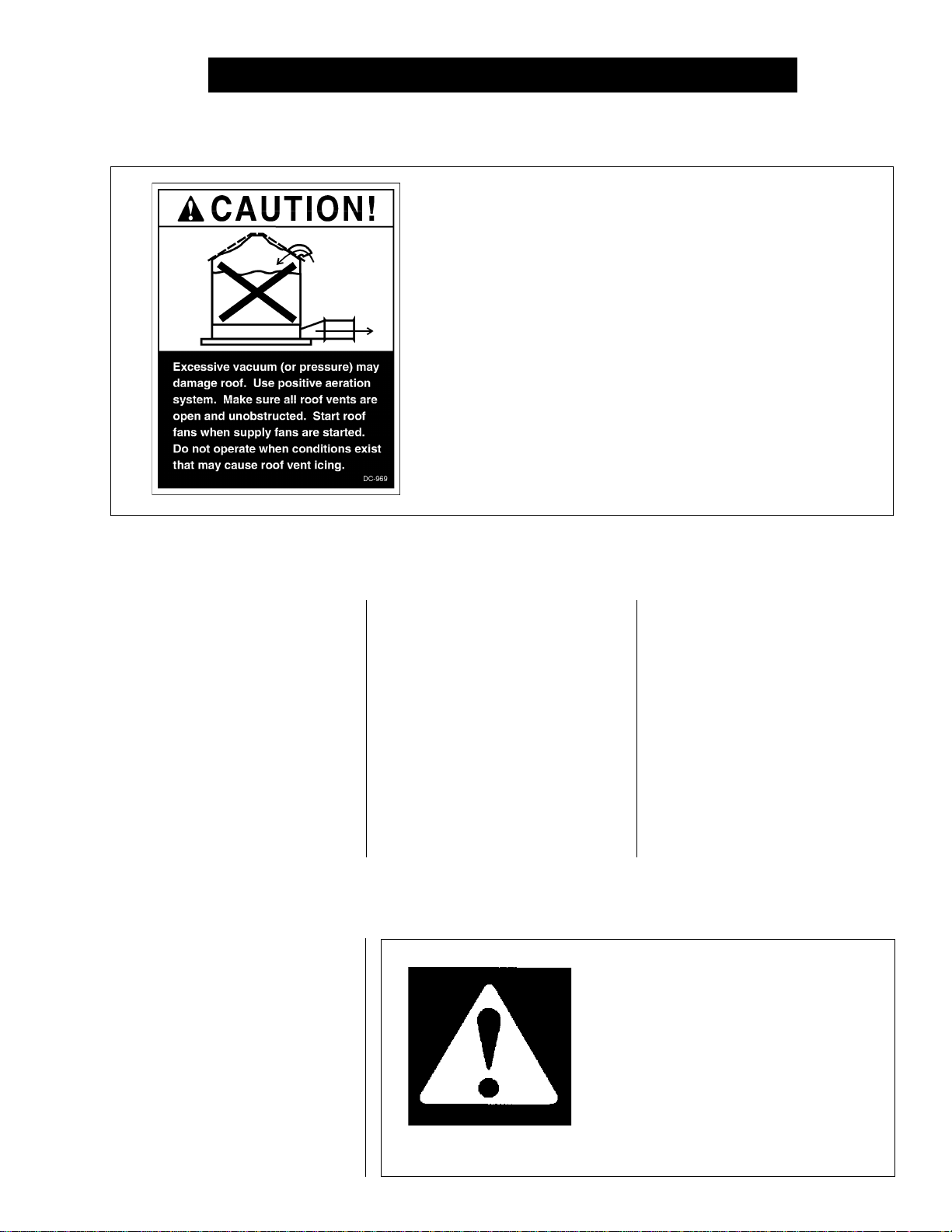
ROOF WARNING, OPERATION & SAFETY
ROOF DAMAGE WARNING AND DISCLAIMER
GSI DOES NOT WARRANT ANY ROOF DAMAGE CAUSED
BY EXCESSIVE VACUUM OR INTERNAL PRESSURE FROM
FANS OR OTHER AIR MOVING SYSTEMS. ADEQUATE
VENTILATION AND/OR "MAKEUP AIR" DEVICES SHOULD
BE PROVIDED FOR ALL POWERED AIR HANDLING SYSTEMS. GSI DOES NOT RECOMMEND THE USE OF DOWNWARD FLOW SYSTEMS (SUCTION). SEVERE ROOF DAMAGE CAN RESULT FROM ANY BLOCKAGE OF AIR PASSAGES. RUNNING FANS DURING HIGH HUMIDITY/COLD
WEATHER CONDITIONS CAN CAUSE AIR EXHAUST OR
INTAKE PORTS TO FREEZE.
Thank you for choosing a GSI/
Airstream product. It is designed
to give excellent performance
and service for many years.
This manual describes the
operation and service for all standard 1100 Series one fan grain
dryers. These models are available for liquid propane or natural gas fuel supply, with either
single phase 230
The symbol shown is used to call
your attention to instructions concerning your personal safety. Watch
for this symbol; it points out important safety precautions. It means
"ATTENTION", "WARNING", "CAUTION", and "DANGER". Read the
message and be cautious to the
possibility of personal injury or
death.
DRYER OPERATION
volt, or three phase 220 or 440
volt electrical power.
The principal concern of the GSI
Group, Inc. ("GSI") is your safety and
the safety of others associated with
grain handling equipment. This
manual is written to help you understand safe operating procedures,
and some of the problems that may
be encountered by the operator or
other personnel.
SAFETY ALERT SYMBOL
WARNING! BE ALERT!
Personnel operating or working around
electric fans should read this manual.
This manual must be delivered with the
equipment to its owner. Failure to read
this manual and its safety instructions is
a misuse of the equipment.
As owner and/or operator, it is
your responsibility to know what
requirements, hazards and precautions exist, and to inform all
personnel associated with the
equipment, or who are in the dryer
area. Avoid any alterations to the
equipment. Such alterations may
produce a very dangerous situation, where serious injury or death
may occur.
5
Page 6

SAFETY ALERT DECALS
Three decals displayed on all Airstream Dryers. Belt drives, chain driven meter rolls
and combustible fuels must be treated with caution.
6
Page 7

SAFETY PRECAUTIONS
1. Read and understand the operating manual before trying to operate the
dryer.
2. Never operate the dryer while the guards are removed.
3. Power supply should be OFF for service of electrical components.
Use CAUTION in checking voltage or other procedures requiring power
to be ON.
4. Check for gas leaks at all gas pipe connections. If any leaks are
detected, do not operate dryer. Shut down and repair before further operation.
5. Never attempt to operate the dryer by jumping or otherwise bypassing
any safety devices on the unit.
6. Set pressure regulator to avoid excessive gas pressure applied to
burner during ignition and
operating procedures. Do not exceed maxi
ing temperature.
7. Keep the dryer clean. Do not allow fine material to accumulate in
the plenum chamber.
8.
Keep auger drive belts tight
when burner is in operation. See chart for
mum recommended dry-
enough to prevent slippage.
USE CAUTION
IN THE OPERATION
OF THIS EQUIPMENT
The design and manufacture of this
dryer is directed toward operator
safety. However, the very nature of
a grain dryer having a gas burner,
high voltage electrical equipment
and high speed rotating parts, does
present a hazard to personnel,
which can not be completely safeguarded against, without interfering
with efficient operation and reasonable access to components.
Use extreme caution in working
around high speed fans, gas-fired
heaters, augers and auxiliary conveyors, which may start without
warning when the dryer is operating
on automatic control.
KEEP THE DRYER CLEAN
DO NOT ALLOW FINE
9. Use CAUTION in working around high speed fans, gas burners,
augers and auxiliary conveyors which START AUTOMATICALLY.
10. Do not operate in any area where combustible material will be drawn into
the fan.
11. Before attempting to remove and reinstall any propellor, make certain
to read the recommended procedure listed within the servicing section
of the manual.
12. Be certain that capacities of auxiliary conveyors are matched to dryer
auger capacities.
13. Clean grain is easier to dry. Fine material increases resistance to airflow
and requires removal of extra moisture.
READ THESE INSTRUCTIONS
BEFORE OPERATION AND SERVICE
SAVE FOR FUTURE REFERENCE
MATERIAL TO ACCUMULATE
IN THE PLENUM CHAMBER
OR SURROUNDING THE
OUTSIDE OF THE DRYER
Continued safe, dependable operation of automatic equipment depends, to a great degree, upon the
owner. For a safe and dependable
drying system, follow the recommendations within this manual, and
make it a practice to regularly inspect the operation of the unit for any
developing problems or unsafe conditions.
Take special note of the safety
precautions listed above before attempting to operate the dryer.
7
Page 8
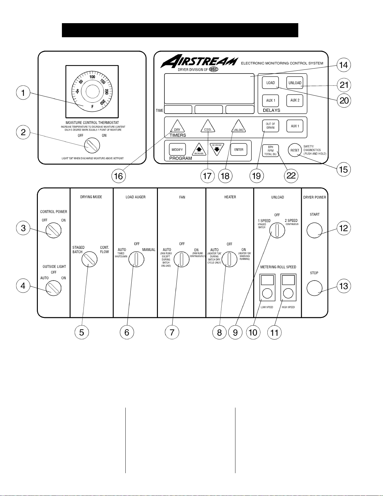
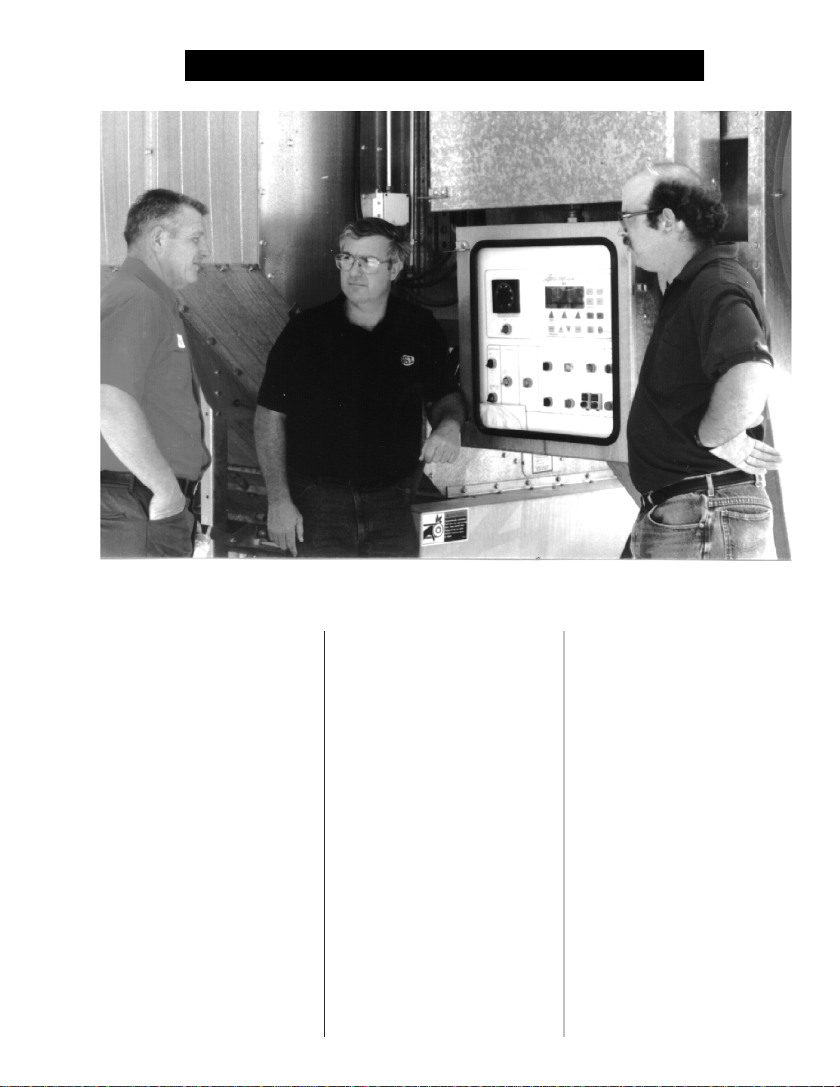
DRYER CONTROL PANEL
Figure 1: The grain dryer control panel with the Electronic Monitoring Control System in the upper right panel.
DRYER CONTROL PANEL FEATURING
THE ELECTRONIC MONITORING CONTROL SYSTEM
The control panel provides easy access to gauges and controls, and the
ILLUMINATED SWITCHES are a
quick reference for every operating
function. The patent pending Elec-
tronic Monitoring Control System
is computerized and gives instant
8
information about dryer operation.
MOISTURE CONTROL
THERMOSTAT (1)
This electronic thermostat controls the moisture level of discharged grain by sensing grain
column temperature.
MOISTURE CONTROL
SWITCH (2)
This switch turns the power ON or
OFF to the moisture control ther-
mostat. It lights up when the grain
column temperature is below the
thermostat set point.
Page 9

DRYER CONTROL PANEL
CONTROL POWER
SWITCH (3)
The power to the Electronic Monitoring Control System is turned
ON or OFF with this switch.
OUTSIDE LIGHT (4)
The dryer service light is turned
ON or OFF here. It also may be
set on AUTO, which turns the light
on while the dryer is running, and
off if a shutdown occurs.
DRYING MODE SWITCH (5)
This is used to select STAGED
BATCH or CONTINUOUS FLOW
drying. The switch will light only after the Electronic Monitoring Con-
trol System has been turned ON,
the safety circuit is okay and the
RESET button has been pressed.
LOAD AUGER SWITCH (6)
This is used to select the operation of the load auger. In both the
AUTO and MANUAL position the
load auger will operate if the dryer
is low on grain, and will automatically shut off when the dryer is full.
In the AUTO position only, the
dryer will shut down after a predetermined period of time set on the
OUT OF GRAIN TIMER, or if grain
flow is interrupted to the dryer. The
switch will light whenever the load
auger is operating.
Note: When this switch is set
to AUTO or MANUAL it also controls the operation of any auxiliary
load equipment being utilized,
such as an auxiliary auger or conveyor.
FAN SWITCH (7)
The fan is turned ON or OFF with
this switch. The ON position operates the fan continuously during
STAGED BATCH and CONTINUOUS FLOW modes. The AUTO position operates the fan in STAGED
BATCH during the dry and cool
cycle. The switch will light up whenever the airflow switch is sensing
airflow and the dryer is full of grain.
HEATER SWITCH (8)
This switch is used to turn the
burner ON or OFF. The AUTO position operates the burner in
STAGED BATCH during the dry
cycle. The ON position will operate
the burner only when the fan is running. The switch will light up when
the flame sensor detects the flame.
UNLOAD SWITCH (9)
The UNLOAD switch turns the metering rolls and discharge auger
ON or OFF, and selects the operation of the metering rolls.
• In the 2 SPEED position if the
MOISTURE CONTROL switch is
ON, and the DRYING MODE
switch is turned to CONTINUOUS
FLOW, the METERING ROLL
SPEED will alternate between the
HIGH speed metering roll potentiometer setting and the LOW
speed metering roll potentiometer
setting depending on the control
signal from the MOISTURE CONTROL THERMOSTAT. The dis-
charge auger will operate continuously.
• In the 1 SPEED position, if the
MOISTURE CONTROL switch is
ON, and the DRYING MODE
switch is turned to CONTINUOUS
FLOW, the METERING ROLL
SPEED will operate at the HIGH
speed metering roll potentiometer
setting or turn OFF depending on
the control signal from the MOISTURE CONTROL THERMOSTAT. The discharge auger will
operate whenever the metering
rolls are operating.
• In both the 1 SPEED or the 2
SPEED position, if the MOISTURE CONTROL THERMOSTAT
is OFF, and the DRYING MODE
switch is turned to CONTINUOUS
FLOW, the METERING ROLL
SPEED can be manually controlled by adjusting the HIGH
speed metering roll potentiometer.
The discharge auger will operate
continuously.
• If the DRYING MODE switch is
turned to STAGED BATCH, the
UNLOAD switch should be set to
the 1 SPEED position. The dis-
charge auger and metering rolls
will only operate during the unload
cycle of the staged batch operation, and the METERING ROLL
SPEED is adjusted using the
HIGH speed metering roll potentiometer.
Note: When this switch is set to
AUTO or MANUAL it also controls
the operation of any auxiliary load
equipment being utilized, such as
an auxiliary auger or conveyor.
9
Page 10
DRYER CONTROL PANEL
LOW SPEED METERING
ROLL POTENTIOMETER (10)
This is used to adjust the LOW
speed of the metering roll when the
2 SPEED and MOISTURE CONTROL THERMOSTAT are in use.
HIGH SPEED METERING
ROLL POTENTIOMETER (11)
This is used to:
• Set the HIGH speed of the meter-
ing roll when the 2 SPEED automatic moisture control feature of
the dryer is utilized.
• Set the speed of the metering
rolls when the 1 SPEED auto-
matic moisture control feature of
the dryer is utilized.
• Set the speed of the metering
rolls during continuous flow operation when the moisture control
is not used.
• Set the rate of grain discharge from
the dryer during the unload cycle of
staged batch dryer operation.
DRYER POWER
START SWITCH (12)
This switch starts and operates the
dryer based on switch settings. If
other switch settings are in the OFF
position, individual dryer compo-
nents can be operated by turning the
DRYING MODE switch to CONTINUOUS FLOW, pressing the
DRYER POWER START button and
then turning ON the desired dryer
component.
DRYER POWER
STOP SWITCH (13)
This switch stops all dryer functions. If an automatic dryer shutdown occurs, first determine and
correct the cause of the shutdown.
Then, press the DRYER POWER
STOP button to reset the dryer before restarting.
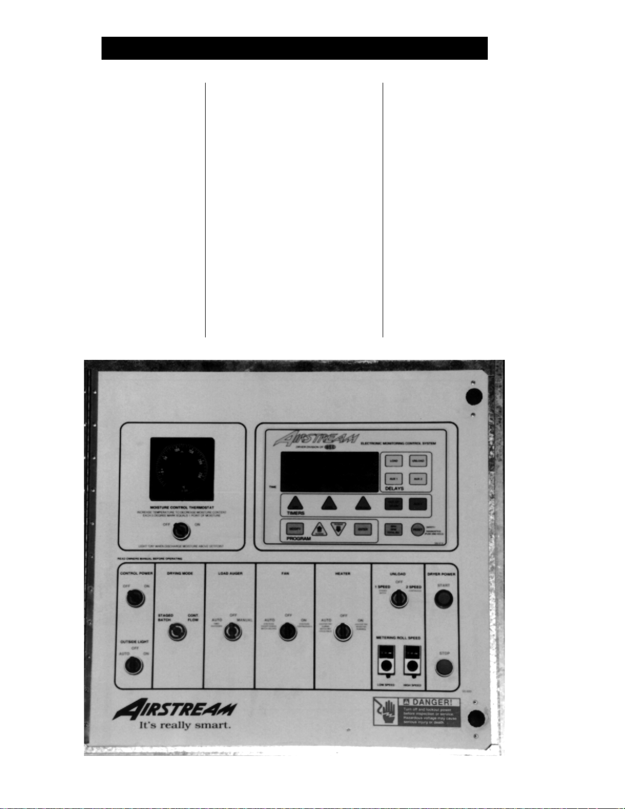
10
The Airstream Dryer Control Panel.
Page 11
DRYER CONTROL PANEL
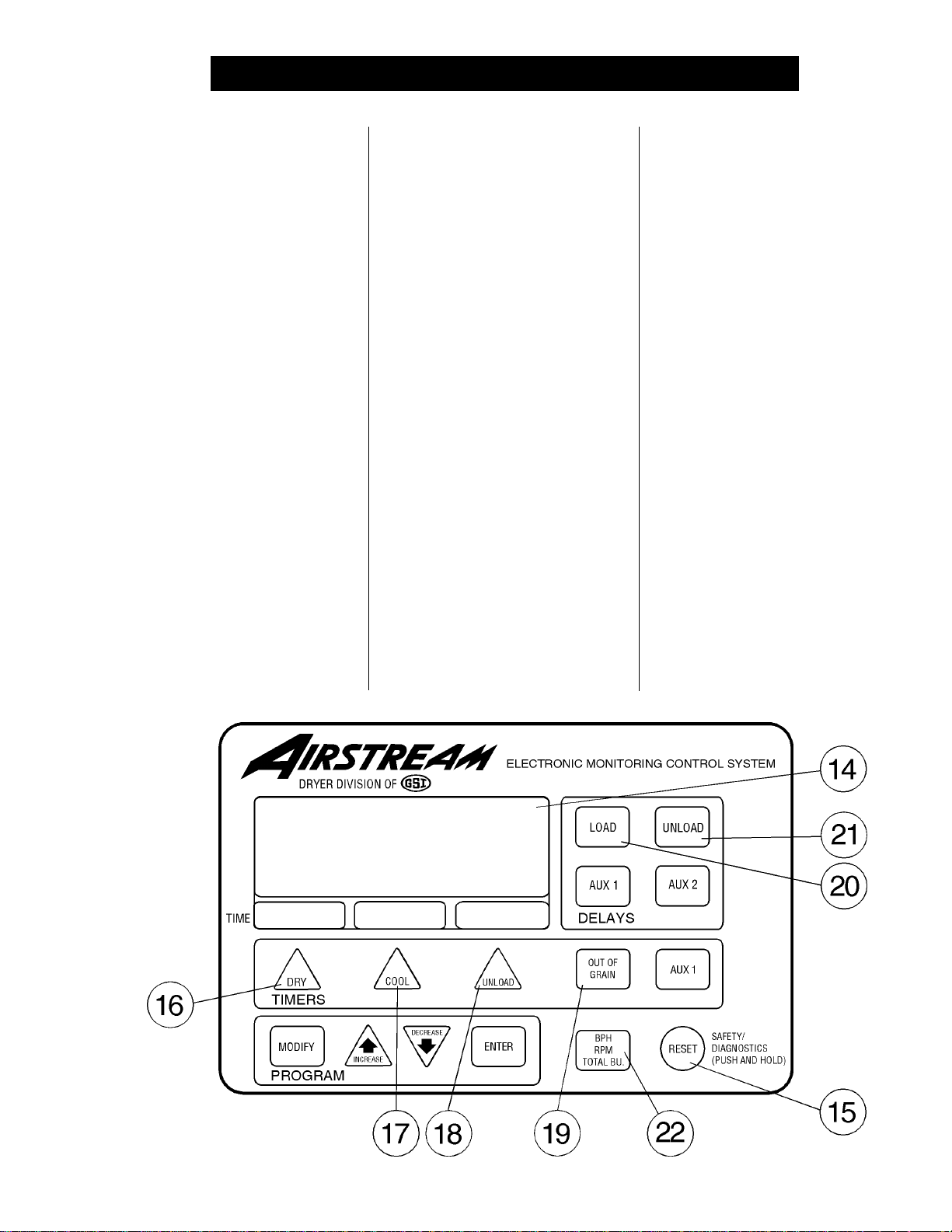
ELECTRONIC
MONITORING CONTROL
SYSTEM (14)
The Electronic Monitoring Control
System (Figure 2) controls all tim-
ing functions and safety circuit
checks. It is designed to simplify
dryer operation by providing printed
messages and warnings on its liquid crystal display (LCD).
TURNING ON THE
ELECTRONIC
MONITORING CONTROL
SYSTEM USING THE
RESET BUTTON (15)
Turn the CONTROL POWER switch
to ON. The monitor will display a
copyright message and model number, total running time in hours and
minutes and the current time and
date. To activate the controller press
the RESET button.
SETTING THE DRY (16),
COOL (17) AND UNLOAD
(18) BATCH TIMERS
These switches are used to set the
cycle times in the STAGED BATCH
DRYING MODE only. The DRYING
MODE switch must be in the
STAGED BATCH position. The current settings on these three TIMERS
are displayed directly above each
TIMER button. To change the setting of these TIMERS follow these
instructions:
1. Press the DRY, COOL or UNLOAD TIMER button.
2. Press the MODIFY button.
3. Press the INCREASE or DECREASE button to adjust the
settings.
4. Press the ENTER button.
During operation the remaining
time on each TIMER is displayed on
the screen. If the power goes out or
if the dryer is stopped, these times
are saved by the controller. When
the dryer is restarted the TIMERS
will continue timing down. The TIMERS will return to their initial settings
by pressing the RESET button.
SETTING THE OUT OF
GRAIN TIMER (19)
If the dryer runs out of grain while
the LOAD AUGER switch is in the
AUTO position, the OUT OF GRAIN
TIMER automatically shuts OFF the
dryer after the period of time preset
on the TIMER. When pressed, the
display will show the amount of time
left on the TIMER and the percentage of time the last load expended.
A second screen will appear showing the TIMER'S setting and will allow the operator to modify it as described for setting the BATCH TIMERS.
Figure 2: The Airtream Electronic Monitoring Control System
11
Page 12
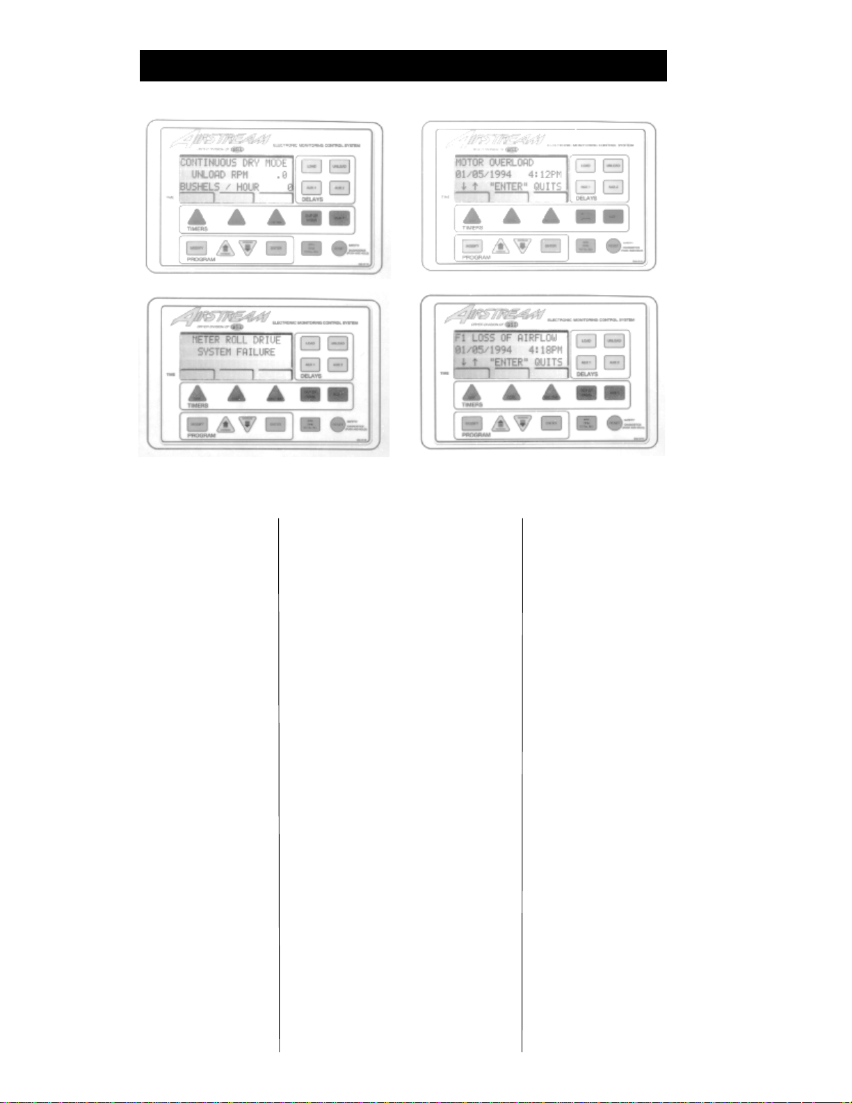
DRYER CONTROL PANEL
The Airstream Electronic Monitoring Control System showing different LCD displays.
SETTING THE LOAD (20)
AND UNLOAD (21) DELAYS
The LOAD DELAY is used to delay
the starting of the load auger when
the dryer is unloading to prevent the
load auger from starting and stopping. The UNLOAD DELAY is used
to control the amount of time the un-
load auger runs after the metering
rolls stop to allow for auger
cleanout. Both the LOAD and UNLOAD DELAYS are set using the
same procedure as the TIMERS.
The AUX1 and AUX 2 DELAYS are
presently not being used.
UTILIZING THE
BUSHEL COUNTER (22)
When operating the dryer the LCD
display will show the DRYER MODE
OF OPERATION on the first line, the
BUSHELS PER HOUR or the METERING ROLL RPM on the second
line and the TOTAL BUSHELS dried
on the third line. By pressing the
BPH/RPM/TOTAL BU button the
second line will alternate between
the METERING ROLL RPM's or the
BUSHEL PER HOUR rate. The TOTAL BUSHELS DRIED reading is
the total since the bushel counter
was last reset. To reset the
BUSHEL COUNTER, press and
hold the RESET button for five seconds. Press the ENTER button
through the date and time settings
and then follow the instructions displayed on the LCD for resetting the
counter.
In the STAGED BATCH DRYING MODE the first line of the LCD
display tells which TIMER is being
used, and the second line switches
between TOTAL BATCHES, UNLOAD RPM or TOTAL BUSHELS.
The third line indicates TOTAL DRY
TIME and the fourth line is TIME
REMAINING on the TIMERS.
DRYER SAFETY CIRCUIT
The Electronic Monitoring Control
System continuously checks all
safety circuits on the dryer, and will
automatically shut the dryer down
should a problem occur. The cause
of the dryer shutdown will be displayed on the LCD display, and a
beeper will sound on the controller.
To restart the dryer after a safety
shutdown, first correct the reason for
the shutdown, and then press the
DRYER POWER STOP button to reset the circuit. Press the START
button.
The Electronic Monitoring
Control System stores in its
memory the time, date and cause for
the last 25 dryer safety shutdowns.
To review this information hold the
RESET button in for five seconds.
The procedure for reviewing the
safety circuit shutdown log will be
displayed on the LCD display.
12
Page 13

DRYER CONTROL PANEL
SAFETY CIRCUIT SHUTDOWN MESSAGES
BURNER VAPOR HIGH
TEMPERATURE
The LP gas vapor temperature sensor located in the gas pipe train
downstream from the vaporizer, has
opened indicating that the vaporizor
is running too hot and must be readjusted. This sensor is set at 200°F
and automatically resets itself when
cool.
BURNER WARNING FLAME
NOT DETECTED
The flame sensor has failed to detect a burner flame indicating that the
burner has failed to light, there is a
problem with the flame sensing circuitry or the dryer is not getting
burner fuel.
FAN HOUSING HIGH
TEMPERATURE
The temperature high limit located
on the fan/burner housing has
opened, indicating an over temperature condition has occurred towards
the rear of the fan/heater housing.
This control is set at 200°F and must
be manually reset.
GRAIN DISCHARGE
WARNING
The lid on the grain discharge box
has opened, indicating that grain is
not being taken away fast enough
at the discharge box.
LOWER ADJUSTABLE
GRAIN HIGH
TEMPERATURE
An over temperature condition has
occurred in the right side (left and
right as viewed from behind the
dryer) grain column causing the
control to shut down the dryer. This
control is set at 210°F and automatically resets itself when cool.
LOWER FIXED GRAIN
HIGH TEMPERATURE
An over temperature condition has
occurred in the left side (left and
right as viewed from behind the
dryer) grain column causing the
control to shutdown the dryer. This
control is set at 210°F and automatically resets itself when cool.
MOTOR OVERLOAD
One of the thermal overloads on
either the fan, load, unload or aux-
iliary motors has opened, indicating an overcurrent condition. The
overloads must be manually reset.
OUT OF GRAIN
WARNING/UNLOAD
CLEANOUT
The dryer has run low on grain, and
the OUT OF GRAIN TIMER has
timed out, shutting the dryer down.
The unload auger will clean out the
dryer if in continuous flow operation.
METERING ROLL DRIVE
SYSTEM FAILURE
The metering roll drive system has
failed to turn. A broken chain or
jammed metering roll is a possibility.
RIGHT METERING ROLL
FAILURE
The right (as viewed from behind the
dryer) metering roll has stopped turning, or the sensor has been damaged.
LEFT METERING ROLL
FAILURE
The left (as viewed from behind the
dryer) metering roll has stopped turn-
ing, or the sensor has been damaged.
12 VOLT POWER
SUPPLY WARNING
The right circuit breaker on the input/output board has tripped.
AUXILIARY SAFETY
SHUTDOWN
A shutdown has occurred due to an
auxiliary installed safety feature.
BURNER SHUTDOWN
LOSS OF AIRFLOW
The contacts in the air switch have
opened due to insufficient airflow for
the burner to operate.
FAN FAILURE
NO AIRFLOW
The contacts in the air switch have
opened due to the fan not turning, or
the air switch may need adjustment.
L1 VOLTAGE LOST
The left circuit breaker located on
the input/output board of the Elec-
tronic Monitoring Control System
has tripped, or one of the hardware
timers has shut down the dryer.
PLENUM HIGH
TEMPERATURE
An over temperature condition has
occurred inside the dryer plenum.
This control is a 300°F limit and automatically resets itself when cool.
FAN CANNOT START
CHECK AIR SWITCH
The air switch contacts have closed
prior to the fan starting, indicating a
freewheeling blade or improper setting of the air switch.
13
Page 14

Before the dryer is filled, thoroughly
inspect the unit and check the operation of the dryer as follows.
INSPECT THE METERING
ROLLS
Open all metering roll access
doors and inspect each compart-
ment for any bolts, nuts or other foreign material, that may cause possible jamming of the metering rolls.
BEFORE ATTEMPTING TO
OPERATE THE DRYER MAKE
DRYER PRE START CHECKS
PRE SEASON INSPECTION
The Maxon safety shut off valve.
SURE ALL SAFETY SHIELDS
ARE IN PLACE, ALL BOTTOM
CLEANOUT AND REAR
ACCESS DOORS ARE CLOSED
AND ALL PERSONNEL ARE
CLEAR OF THE DRYER
SET CONTROL SWITCHES
Moisture Control Switch-ON
Moisture Control Thermostat-MAXI-
MUM TEMPERATURE
Load Switch-OFF
Unload Switch-OFF
Fan Switch-OFF
Burner Switch-OFF
Out of Grain Timer-8 MINUTE
Load Delay-30 SECONDS
Unload Delay-30 SECONDS
Metering Roll Speed-LOW AND
HIGH SPEED SETTINGS PUT
ON ZERO
Dry Timer-60 MINUTE
Cool timer-20 MINUTE
Unload timer-10 SECONDS
Mode Switch-CONTINUOUS FLOW
14
ELECTRICAL POWER
Turn ON the electrical power supply to the dryer, set all circuit breakers to ON, including the safety disconnect handle mounted on front
of the dryer's power panel.
CONTROL POWER
SWITCH
Turn the CONTROL POWER switch
to ON. The switch will light up. A
copyright message, model number,
total running time in hours and minutes, current date and time will appear. At this point the controller will
lock out all other dryer functions.
Once the date and time appear,
press RESET and the dryer will perform its safety circuit check. If a fault
is found, the cause will be displayed
on the LCD. If all are found safe, the
controller will supply power to the
electronic fuel shut- off valve (if
so equipped) and the DRYING
MODE switch will light up, indicating
that the dryer is ready to be started.
POWER START BUTTON
Push the DRYER START button,
and all the selector switches on the
control panel will be activated.
FUEL CHECK
If using LP gas, make sure the tank
has plenty of fuel and that the tank
does not have a regulator mounted
to it. If using natural gas, make sure
an adequate supply is available.
If using LP gas, slowly OPEN
the main fuel supply valve at the
tank. If using natural, gas turn ON
the valve along the supply line.
Then, OPEN the electronic shut off
valve (Maxon valve), if so equipped,
or OPEN the manual shut off valve
on the dryer to allow fuel flow to the
dryer. Inspect all gas lines and con-
nections for possible leaks.
Any gas leaks need to be
fixed immediately!
Page 15
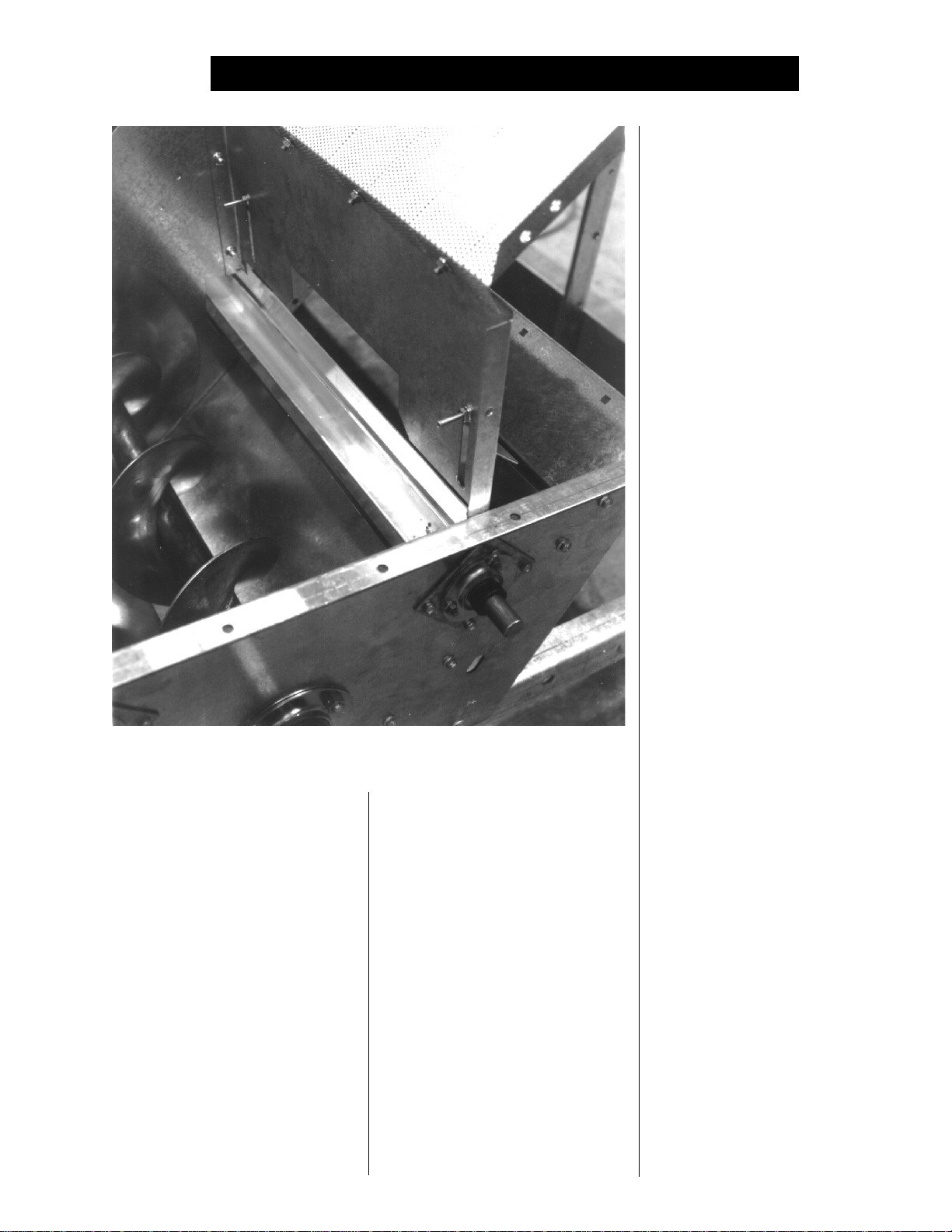
The metering roll access area.
LOAD AUGER
With the grain supply SHUT OFF,
quickly bump the LOAD AUGER
switch to MANUAL, and see if the
load auger rotates clockwise as
viewed from the drive end, or counterclockwise if the dryer is a front
load model. If the wet grain supply
auxiliary is wired to the dryer it
should also rotate in the correct direction at this time. Turn the LOAD
AUGER switch to the AUTO position. The top auger and wet grain
supply auxiliary should run for one
minute, and then the dryer will shut
down leaving the safety shutdown
DRYER PRE START CHECKS
message (out of grain warning) displayed. Press the DRYER POWER
STOP button to reset the panel, then
press the START button.
ONE SPEED OPERATION
To check 1 speed operation place
the UNLOAD switch in the 1 SPEED
setting. Turn up the HIGH SPEED
METERING ROLL DIAL until the
metering rolls start rotating. The
bottom auger should rotate coun-
terclockwise as viewed from the
drive end. The metering roll drive
motor should rotate clockwise as
viewed from the drive end of the
gear box. If the dry grain take away
auxiliary is wired to the dryer, it
should start and rotate in the proper
direction.
MOISTURE CONTROL
THERMOSTAT
To check the MOISTURE CONTROL THERMOSTAT leave the
UNLOADING switch on 1 SPEED,
and slowly turn down the MOISTURE CONTROL THERMOSTAT.
As the setting is decreased, the indicator light should come on and the
metering rolls should stop operating. The bottom auger will stop after the 30 second clean out delay,
providing that the dryer is still being
held by the MOISTURE CONTROL
THERMOSTAT. Rotate the MOISTURE CONTROL THERMOSTAT
up to its maximum setting. The light
should go off, and the metering
rolls should restart along with the
bottom auger if it has stopped.
To check 2 SPEED operation
move the switch to the 2 SPEED position, set LOW speed on 200 and
HIGH speed on 600. Slowly turn the
thermostat until the MOISTURE
CONTROL switch light comes ON.
The METERING ROLL SPEED is
now controlled by the LOW speed
dial. Turning the THERMOSTAT the
other way until the light goes out now
leaves the metering rolls controlled
by the HIGH SPEED DIAL.
METERING ROLL
OPERATION
To check the metering roll operation
turn either the LOW speed or HIGH
speed knob clockwise, and the ME-
15
Page 16
DRYER PRE START CHECKS
TERING ROLL SPEED should increase. Turning either knob counterclockwise will decrease the
speed. Make sure the drive chain
tension is properly adjusted and all
sections of the metering rolls rotate. Turn the UNLOAD switch OFF
after these checks are complete.
The bottom auger will continue to
run for 30 seconds after the switch
is turned OFF to allow for cleanout.
FAN SWITCH
Bump the FAN switch and observe
the fan rotation. The fan should run
counterclockwise. Sometimes on
three phase models all motors will
run backwards. They can easily be
reversed by interchanging the two
of three power supply wires. Reverse the two outside wires, L1 and
L3, and leave the middle one in the
same position.
Note: If the dryer is empty, the
burner will not operate. The fans
cannot create enough static pressure to engage the air switch. You
will receive a loss of airflow message.
ignite after a short purge delay of approximately 10 seconds. Gas pressure should be shown on the gauge.
At this time adjust the BURNER
HIGH-LOW FIRE THERMOSTAT to
200°F, causing the burner to operate on high-fire. The thermostat is
located on the front left side of the
dryer. Observe the gas pressure on
gauge, and turn the thermostat to
its MINIMUM SETTING, causing the
burner to cycle into low-fire. As the
burner thermostat is turned down
the gas pressure should also show
a noticeable drop, indicating that the
high-fire solenoid is closed and the
burner is being supplied with less
gas through the low-fire control
valve. At this time set the high-
fire and low-fire pressure settings.
Use the PRESSURE REGULATOR
for high-fire and the BALL VALVE
for low-fire. The thermostat should
cycle between high and low, approximately 4 to 5 times per minute.
Approximate settings should be:
LP Gas High-Fire 6-15 lbs.
Low-Fire 2-6 lbs.
Natural Gas High-Fire 6-10 lbs.
Low-Fire 1-3 lbs.
If the burner remains on high-
fire and does not cycle, INCREASE
the regulator setting on the propane
models, or the supply valve on the
natural gas models in order to reach
the thermostat setting. If the
burner remains in low-fire and does
not cycle, slightly DECREASE gas
7
5
BURNER SAFETY
To check the burner safety function,
first make sure the main GAS
VALVE is OFF. Turn the FAN switch
ON and allow the fan to start. Then,
turn the HEATER switch ON. The
dryer will shut down after 20 seconds.
The safety message, "Burner 1 warning flame not detected" will appear.
BURNER TEST FIRE
START the fan, and then turn the
HEATER switch to ON. Turn ON the
fuel supply, and the burner should
16
3
4
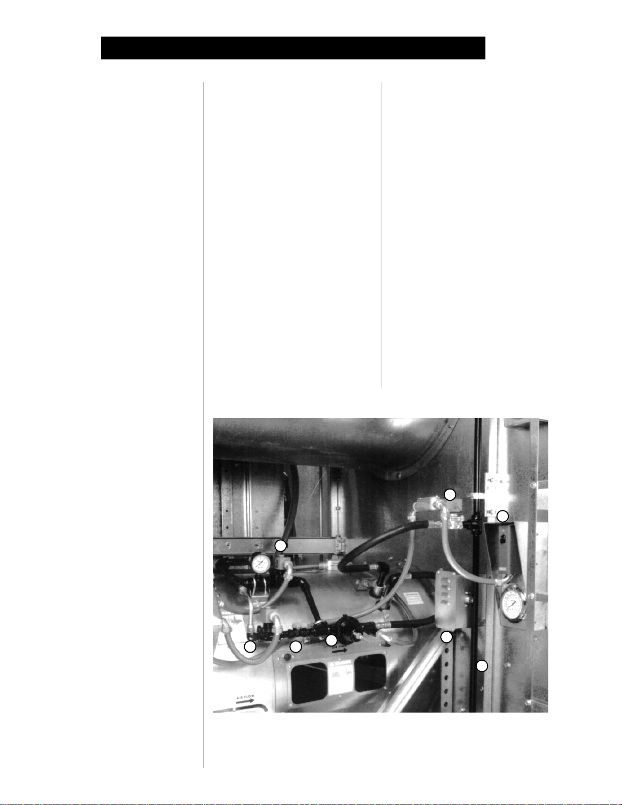
The dryer fan and heater controls featuring: 1-pressure regulator, 2-low-fire
control valve, 3-high pressure solenoid, 4-low pressure solenoid, 5-high-
low fire thermostat (assembly includes thermometer), 6-fuel supply line, 7-
LP solenoid or supply ball valve(NG) and 8-air pressure switch.
2
1
8
6
Page 17
DRYER PRE START CHECKS
All dryer functions should be checked before operation each season.
pressure with the LOW-FIRE CONTROL VALVE. If the gas pressure
is decreased too much a popping or
fluttering sound will be heard. Also,
anytime the high pressure side is
adjusted the low pressure side
needs to be checked.
STAGED BATCH CHECK
To check the staged batch operation, turn the CONTROL POWER
switch to the ON position. Press the
RESET button, OPEN the main
FUEL SUPPLY VALVE at the tank
on an LP dryer or valve in the fuel
supply line on a natural gas dryer.
Turn the DRYING MODE switch to
the STAGED BATCH position.Turn
ON the electric SHUT OFF
VALVE to allow fuel flow to the
dryer, if so equipped. Turn the
LOAD switch to AUTO and UNLOAD switch to 1 SPEED. Push
the DRYER POWER START button and the controller will sequentially start all dryer components in
their proper order. If any switches
are not in their correct position for
staged batch operation, the dryer
will indicate improper switch position, and will not start until the
switches are in the proper position.
After starting, all batch timers will
time down in sequence. When the
unload cycle is complete the timers will automatically reset to their
original settings, and start the dry
timer again.
DRYER SHUTDOWN
To shutdown the dryer, first CLOSE
the FUEL SUPPLY VALVE at the
tank or valve along the fuel line. If
the burner is operating, let the dryer
run out of fuel, and it will shutdown
automatically due to loss of flame.
CLOSE the FUEL VALVE at the
dryer, and press the DRYER
POWER STOP button. Turn OFF
the safety disconnect handle on
the front of the power box, and turn
OFF the main POWER to the dryer.
EMERGENCY
In case of emergency push the dryer
POWER STOP button. The fan,
burner and all augers will stop immediately.
17
Page 18

DRYER START UP
CONTINUOUS FLOW AND CONTINUOUS BATCH START UP PROCEDURE
At the beginning of each harvest and
before filling the dryer with grain
make sure to inspect the dryer for
rodent damage, proper belt and
chain tension and missing or damaged safety shields. Test operate
the dryer using the prestart check
procedures located on pages 14-17.
1. Before attempting to operate the
dryer make sure that all safety
shields are in place, all plenum
bottom closure panel doors
are closed, all rear access
doors are closed and all per-
sonnel are clear of the grain
dryer and grain handling machinery.
2. Turn all SELECTOR switches
on the control panel to the OFF
position.
3. Turn ON the electric POWER
supply to the dryer, and move
the safety disconnect handle
mounted on the dryer's upper
power box to ON.
4. Turn the CONTROL POWER
switch to ON. The switch will
light up. A copyright message,
model number, total running
time in hours and minutes, current date and time will appear.
At this point the controller will
lock out all other dryer functions.
Once the date and time appear,
press RESET, and the dryer will
perform its safety circuit checks.
If a fault is found the cause will
18
be displayed on the LCD. If all
are found safe the controller will
allow the electronic FUEL SHUT
OFF valve to be manually
OPENED (if so equipped), and
the DRYING MODE switch will
light up, indicating that the dryer
is ready to be started.
5. Move the LOAD AUGER switch
to MANUAL, and push the dryer
POWER START switch. The
top auger will immediately start,
and the LOAD AUGER switch
will light up. If additional grain
handling equipment is wired to
the dryer it will also start immediately.
6. When the dryer is full of grain
the top auger will stop auto-
matically, and any grain handling equipment wired to the
dryer will also stop.
CONTINUOUS FLOW
OPERATION
1. Turn the CONTROL POWER
switch to ON.
2. After the date and time appear
on screen, press the RESET
button.
3. Push the dryer POWER START
switch.
4. OPEN the main FUEL SUPPLY
VALVE on the tank if using LP
gas, or OPEN the FUEL SUP
PLY LINE if using natural gas.
Turn ON the electric SHUTOFF,
Maxon valve (if so equipped), or
OPEN the manual SHUTOFF
valve to allow fuel flow to the
dryer.
5. Turn the DRYING MODE switch
to CONTINUOUS FLOW.
6. The dryer should already be
filled with grain. Turn the
LOAD AUGER switch to the
AUTO position. In both the auto
and manual positions the dryer
grain level switch will automatically keep the dryer full of grain.
In the auto position the dryer will
shut down after a preset time
period on the out of grain timer.
7. Turn the FAN switch to ON. The
fan will start, and the switch will
light up when airflow is detected.
8. Start the burner by turning the
HEATER switch to ON. After
purging for approximately 10
seconds the burner will fire, and
the heater switch will light up.
This indicates that the flame
sensing circuit is sensing burner
flame. For information concerning burner adjustment see the
pre start section of this manual.
9. Operate the heaters to dry grain
for 6-7 minutes per point of
moisture to be removed with the
plenum temperature set at
180°F. Example: Shelled corn
starts with 25% moisture and
Page 19

DRYER START UP
the final moisture content is to
be 15% (10% removal). Using
the all heat dryeration process,
the estimated drying time is 60
minutes (10 x 6).
10. While operating the dryer adjust
the METERING ROLL dials to
the recommended settings. See
the chart on page 00.
11. To move grain through the dryer
turn the MOISTURE CONTROL
switch to ON. The switch will
light up.
Note: When the UNLOAD switch is
in the 2 SPEED position, and the
MOISTURE CONTROL THERMOSTAT switch is OFF, the speed of
the metering rolls can be manually
adjusted by turning the HIGH
SPEED METERING ROLL dial.
Turning the dial clockwise will INCREASE the grain discharge rate,
counterclockwise will DECREASE
the discharge rate. (The numbers on
the speed dials indicate the percentage of full speed.)
12. At the end of the start-up period, start the flow of grain out
of the dryer. Turn the UNLOAD
switch to the 2 SPEED position. The bottom auger and
metering roll will immediately
start, and the unload switch will
light. If additional grain handling equipment is utilizing the
unload auxiliary overload supplied with the dryer, this equipment will also immediately
start.
13. To shut the dryer down, CLOSE
the FUEL SUPPLY VALVE at
the fuel tank or fuel source. Let
the dryer run until the fuel supply lines drain, and the dryer
automatically shuts down due to
loss of flame. CLOSE the FUEL
valve at the dryer. Press the
DRYER POWER STOP button.
Turn OFF the dryer's SAFETY
DISCONNECT handle. Turn
OFF the MAIN POWER supply
to the dryer.
14. In case of emergency push the
dryer STOP button. The fan,
burner and all augers will stop
immediately.
Note: The Electronic Monitoring
Control System can be used to automatically start the dryer. Place all
the control panel SELECTOR
switches in the PROPER POSITION, and OPEN the electric FUEL
SHUT OFF valve before PRESSING
the DRYER POWER START button.
The controller will start all dryer components in their proper order.
STAGED BATCH
OPERATION
1. Turn the CONTROL POWER
switch to ON.
2. Make sure the DRYING MODE
switch is turned to STAGED BATCH.
3. After the date and time appear,
PRESS the RESET button.
4. OPEN the main FUEL SUPPLY
VALVE on the tank if using LP
gas or the valve in the FUEL
SUPPLY LINE if using natural
gas. Turn ON the ELECTRIC
SHUT OFF, Maxon valve (if so
equipped), or OPEN the manual
SHUT OFF valve to allow fuel
flow to the dryer.
5. The dryer should already be
filled with grain. Turn the LOAD
AUGER switch to AUTO. In both
the auto and manual position,
the grain level switch will automatically keep the dryer full of
grain. In the auto position, the
dryer will shut down after the
preset time period on the OUT
OF GRAIN TIMER, or if the
grain flow to the dryer is interrupted.
6. Turn the FAN switch to AUTO.
The fan will start, and the switch
will light up when airflow is detected.
7. Start the burner by turning the
HEATER switch to AUTO. After purging for approximately
10 seconds the burner will fire,
and the heater switch will light
up indicating that the flame
sensing circuit is sensing
burner flame. For information
concerning burner adjustment
see the pre start section of this
manual.
8. To properly set the correct dry,
cool and unload time for various
moisture content grains. See the
chart on page 00.
19
Page 20

DRYER START UP
9. If the dryer is being operated in
all heat, turn the FAN switch to
ON. In this position the fan will
run continuously during the dry,
cool and unload stages of the
staged batch operation. If the
dryer is being operated in the
dry and cool mode, the preferred
position for the FAN switch is the
ON position, so the fan will run
continuously. If desired, the fan
can be turned off during the unload cycle of the dry-cool-unload
sequence by turning the FAN
switch to AUTO.
10. If the dryer is being operated in
all heat, turn the HEATER
switch to ON. The burner will
operate whenever the fan is
operating. If the dryer is being
used in dry and cool, turn the
HEATER switch to AUTO and
the burner will automatically
shutdown during the cooling and
unloading cycles.
11. Turn the UNLOAD switch to the
1 SPEED position. The bottom
auger and metering rolls will
start automatically during the
unload cycle of the dry-coolunload mode, along with any
grain handling equipment that
is wired to the dryer. The
speed at which the metering
rolls operate during the unload
cycle is adjusted by using the
HIGH SPEED METERING roll
dial. Turning the dial clockwise
will INCREASE the grain discharge rate, and counterclock
wise will DECREASE the discharge rate.
12. To control the length of the dry
cycle using only the dry time
setting programmed into the
system, turn the MOISTURE
CONTROL setting to OFF. To
use the automatic moisture control so that the dry time is determined, not only by the dry time
setting, but also by the moisture
content of the drying grain, turn
the MOISTURE CONTROL
switch to ON.
13. To start the drying operation
push the dryer POWER START
button. The controller will start
all the dryer components in their
proper order. If any of the selected switches are improperly
positioned for staged batch drying, the display will indicate the
proper switch position, and will
not allow the dryer to operate
until the position of the switch is
corrected.
14. To shutdown the dryer, CLOSE
the FUEL SUPPLY valve at the
fuel tank or fuel source. If the
burner is operating, let the dryer
run out of fuel causing an automatic shutdown due to a loss of
flame. CLOSE the FUEL VALVE
at the dryer, and press the dryer
POWER STOP button. Turn
OFF the dryer's main CIRCUIT
BREAKER located on the front
of the power panel. Turn OFF
the MAIN main POWER SUPPLY to the dryer.
15. In case of an emergency press
the dryer POWER STOP button.
The burner, fan and all augers
will stop immediately.
FAN & HEATER SWITCH SETTINGS
Fan Setting
Auto
Auto
On
On
At the end of the dry cycle in staged batch, the fans and heaters will continue running if in the Auto-Auto setting, until the preset tempera-
20
Heater Setting
Auto
On
On
Auto
Fans stay on during dry and cool
Fans stay on during dry and cool
ture on the moisture control thermostat is reached.
Fan Function
cycle only
cycle only
Fans are on continuously
Fans are on continuously
Heater Function
Burners stay on during dry timer cycle
only
Burners stay on during dry and cool
Burners are on continuously
Burners shut down at the end of the
dry cycle
Page 21

DRYER START UP
1100 SERIES BATCH TIMER SETTINGS
Initial
Moisture
17%
18%
19%
20%
21%
22%
23%
24%
25%
26%
27%
Moisture
Removed
2 pts.
3 pts.
4 pts.
5 pts.
6 pts.
7 pts.
8 pts.
9 pts.
10 pts.
11 pts.
12 pts.
Full Heat
Fan & Burner Switches on Manual
Approx.
Dry Time
16 min.
21 min.
26 min
31.5 min.
37 min.
41.5 min.
47 min.
51 min.
54 min.
58 min.
62 min.
Dry
6 min.
11 min.
16 min
21.5 min.
27 min.
31.5 min.
37 min.
47 min.
44 min.
48 min.
52 min.
Cool
0
0
0
0
0
0
0
0
0
0
0
Unload*
10 min.
10 min.
10 min.
10 min.
10 min.
10 min.
10 min.
10 min.
10 min.
10 min.
10 min.
Dry & Cool
Fans on Manual Burners on Auto
Approx.
Dry Time
18 min.
24 min.
30 min
35 min.
40 min.
45 min.
50 min.
55 min.
60 min.
65 min.
70 min.
Dry
18 min.
24 min.
30 min
35 min.
40 min.
45 min.
50 min.
55 min.
60 min.
65 min.
70 min.
Cool
18 min.
18 min.
18 min
18 min.
18 min.
18 min.
18 min.
18 min.
18 min.
18 min.
18 min.
Unload*
10 min.
10 min.
10 min.
10 min.
10 min.
10 min.
10 min.
10 min.
10 min.
10 min.
10 min.
28%
29%
30%
31%
32%
33%
34%
35%
These are approximate starting points.
*Set unload metering roll high speed setting to 999. If unload equipment cannot adequately keep up, lower the speed
setting and add time to the unload timer setting to completely unload the batch. In full heat mode, the time added to the
unload timer will need to be substracted from the dry timer. If fan is on auto and does not run during unload, set cool timer
to 25 minutes.
New unload time calculation = present unload time new dial setting
13 pts.
14 pts.
15 pts.
16 pts.
17 pts.
18 pts.
19 pts.
20 pts.
66.5 min.
71.5 min.
76 min.
81 min.
86 min.
91 min.
96 min.
100 min.
Example
13.75 = 11 ÷ 800
56.5 min.
61.5 min.
66 min.
71 min.
76 min.
81 min.
86 min.
90 min.
1000
0
0
0
0
0
0
0
0
10 min.
10 min.
10 min.
10 min.
10 min.
10 min.
10 min.
10 min.
1000
75 min.
80 min.
85 min.
90 min.
95 min.
100 min.
105 min.
110 min.
75 min.
80 min.
85 min.
90 min.
95 min.
100 min.
105 min.
110 min.
18 min.
18 min.
18 min.
18 min.
18 min.
18 min.
18 min.
18 min.
10 min.
10 min.
10 min.
10 min.
10 min.
10 min.
10 min.
10 min.
21
Page 22

QUICK START UP PROCEDURE
Standard electrical safety practices
and codes should be used when
working with a dryer. Refer to the
National Electric Code Standard
Handbook by the National Fire Protection Association. A qualified elec-
trician should make all wiring installations.
ALWAYS DISCONNECT
AND LOCK OUT POWER
BEFORE WORKING ON OR
AROUND DRYER
FULL START UP CHECK
This start up procedure assumes the following:
1. That you have read and understand the dryer operation and service
manual.
2. That you have taken special note of all safety precautions.
3. That all safety shields are in place.
4. That all metering roll access doors have been opened and all foreign
objects have been removed.
5. That you have done a pre start up check out.
6. That all motors have been checked for proper rotation.
7. That all heaters have been test fired.
8. That the fuel has been turned ON at the tank.
9. That the electric power has been turned ON.
10. That the main DISCONNECT switch on the dryer is ON.
11. That you have wet grain in the wet holding bin.
12. That you know the incoming grain moisture.
13. That you have the dry grain take away equipment in place.
14. That you have the grain going to the proper bin.
15. That all SWITCHES have been set to the OFF position.
16. That the load mercury switch box is installed with the side stamped
up, in the up position.
FILLING THE DRYER
1. Turn the green CONTROL POWER switch to ON. It should light up, go
through 4 screens and end with the time and date.
2. Turn the DRYING MODE switch to CONTINUOUS FLOW.
3. Push the RESET on the computer key pad to activate the computer.
4. Make sure the UNLOAD switch is in the OFF position.
5. Push the DRYER POWER start switch, it should light up.
6. Turn the LOAD AUGER switch to the MANUAL position to fill the dryer.
The load auger should start and run until the dryer is full, then shut off
automatically. (If the switch is set to the auto position the dryer will
shut down each time the out of grain timer times out, and will have to be
restarted.)
7. When the dryer has filled, turn the LOAD AUGER switch to the AUTO
position.
22
Page 23

QUICK START UP PROCEDURE
STARTING THE DRYER
This start up procedure is for a cold start on wet grain for continuous flow
operation.
1. Set the MAXON or FAST ACTION HAND VALVE on the incoming fuel
line to the ON position.
2. Make sure the MOISTURE CONTROL switch is in the OFF position.
3. Turn the FAN switch (or switches if a multi-fan dryer) to the ON position. The light in the switch should light when the fan comes up to
about half speed.
4. Adjust the PLENUM AIR PRESSURE switch if necessary. Use a flat
blade screwdriver counterclockwise to make it more sensitive (taking
less pressure to activate it), or clockwise for the opposite effect.
5. Turn the HEATER switch (or switches if a multi-fan dryer) to the ON
position. The heater will purge for about 10 seconds then ignite. The
light in the heater switch will come on during ignition and will stay on if
the heater ignites. If the heater does not ignite, the light will go out after
trial for ignition and the dryer will shut down, indicating that it did not
light. If this happens check gas supply, and all valves in the fuel line to
make sure they are on.
ADJUSTING THE TEMPERATURE
1. Set the HIGH-LOW FIRE PLENUM THERMOSTAT on the left side of
the dryer to the drying temperature that you want to run (180° to 200°).
On multiple module dryers set the plenum chambers 30° to 60° apart.
Hottest at the top, most cool at the bottom.
2. On LP gas models adjust the PRESSURE REGULATOR (high fire) on
the burner fuel line, so that burner will reach the thermostat setting
and switch to (low fire) (pressures may be required up to 25 lbs.). Natural gas does not have a regulator, but uses a LARGE BALL VALVE
close to the vertical supply line for adjustment (pressures may be required up to 18 lbs.).
On LP gas models adjust the small RED HANDLED BALL VALVE
(low fire) so that the burner maintains flame then switches back to (high
fire). Natural gas has a BALL VALVE close to the burner control box,
for low fire adjustment.
3. Adjust the burner pressure so that the burners cycles 4 times per
minute (approx. 10 sec. on high--approx. 5 sec. on low). When on
high fire increasing the pressure with the PRESSURE REGULATOR
DECREASES the time spent on high fire. When on low fire increasing
the low fire pressure with the RED BALL VALVE INCREASES the time
spent on low fire.
4. On LP gas models adjust the VAPORIZER so the fuel pipes going to
How much gas pressure do I
use? See step number two in
the Adjusting The Temperature
section.
How often should my burner
cycle? See step number three
in the Adjusting The Temperature
section.
23
Page 24

QUICK START UP PROCEDURE
the burner from the regulator are warm to the touch (not hot and cold).
The vaporizer can be adjusted two ways:
•Loosen the bolt in the hinging mechanism and swing it to a
hotter or cooler position, or
•Loosen the two bolts in the hinge pipe and slide the vaporizer
in or out to a cooler or hotter position.
Either one or both methods may have to be used to get the vaporizer to
the proper temperature. Natural gas does not use a vaporizer.
FULL HEAT-CONTINUOUS FLOW OPERATION
How often do I make speed
adjustment? See step number
ten in the Full Heat-Continuous
Flow Operation section.
1. Check the Continuous Flow Metering Roll Settings-Full Heat on page
25. Pick the line that has your initial starting moisture. These are the
settings we will be referring to during this start up procedure.
2. Make sure the UNLOAD switch is OFF.
3. Make sure the MOISTURE CONTROL switch is OFF.
4. Run the fan(s) and heater(s) for about 10% longer than the approxi-
mate drying time required for the moisture you are trying to dry.
5. Example: 10% removal would be about 54 minutes, 15% removal would
be about 76 minutes and 20% removal would be about 100 minutes.
Add 10 minutes to insure that the grain is dry.
6. After the time in step 4 turn the UNLOAD to 1 SPEED and set the
METERING ROLL SPEED, HIGH SPEED potentiometer to the setting
for 1 SPEED operation. Grain should begin to run at this time. Run time
for this is about 10% longer than the approximate drying time required
for the moisture you are trying to dry, as shown in the example #5 above.
This allows the moisture in the dryer to reach an even gradient top to
bottom without having any highs or lows in it. It will, however, overdry
some of the corn a little.
7. Increase the drying temperature to 190° for single fans or for multiple
fan dryers set the heat chambers 30° to 60° apart. Hottest at the top,
most cool at the bottom.
8. DO NOT TRY TO ADJUST THE DRYER FOR MOISTURE DURING
THIS PROCESS OR YOU WILL ESTABLISH HIGH AND LOW
SWINGS IN THE MOISTURE CONTROL. IT WILL TAKE SEVERAL
HOURS TO WORK ITSELF OUT.
9. After the run time in step 6 you are ready to set up the moisture control.
Now turn the MOISTURE CONTROL to the ON position. Set the temperature to about 100°.
10. Turn the UNLOAD to 2 SPEED. Set the METERING ROLL SPEED,
LOW SPEED and HIGH SPEED potentiometer to the settings listed for
them. Let the dryer run on these settings as shown in the example #5
before trying to adjust moisture or meter roll settings. These settings
24
Page 25

QUICK START UP PROCEDURE
will not have your grain moisture adjusted exactly where you want it, but
will be a good place to start initially. A little different moisture at the
bottom of the storage bin is not usually a problem as long as you have
full floor aeration.
11. After the run time in step 10 you are ready to adjust the moisture control,and the meter roll speeds if required. Each time you make an
adjustment to the moisture control, it will take the approximate time shown
in example #5 to see the results.
1100 SERIES CONTINUOUS FLOW METERING ROLL SETTINGS
Full Heat
Initial
Moisture
Moisture
Removed
Approx.
Dry Time
1 Speed
2 Speed
Low
2 Speed
High
17%
18%
19%
20%
21%
22%
23%
24%
25%
26%
27%
28%
29%
30%
2 pts.
3 pts.
4 pts.
5 pts.
6 pts.
7 pts.
8 pts.
9 pts.
10 pts.
11 pts.
12 pts.
13 pts.
14 pts.
15 pts.
16 min.
21 min.
26 min
31.5 min.
37 min.
41.5 min.
47 min.
51 min.
54 min.
58 min.
62 min.
66.5 min.
71.5 min.
76 min.
625
476
385
317
270
241
213
196
185
172
161
150
140
132
317
270
241
213
196
185
172
161
150
140
132
123
116
110
875
775
675
575
476
385
317
270
241
213
196
185
172
161
31%
32%
33%
34%
35%
These are approximate starting points.
16 pts.
17 pts.
18 pts.
19 pts.
20 pts.
81 min.
86 min.
91 min.
96 min.
100 min.
123
116
110
104
100
104
100
096
087
082
150
140
132
123
116
25
Page 26

QUICK START UP PROCEDURE
ADJUSTING THE MOISTURE CONTROL
How do I set my moisture
control? See step number one
in the Adjusting The Moisture
Control section.
1. Each 5° on the MOISTURE CONTROL changes the output moisture by
about 1%. Example: 100° is set, producing 16% corn out, however,
17% corn out is needed. Reduce the MOISTURE CONTROL temperature by 5° to 95°. This should change the moisture out to about 17%. To
make the corn come out dryer, raise the temperature on the MOISTURE
CONTROL.
2. There are 4 sensors that are averaged together for sensing MOISTURE CONTROL temperature, 1 on each side of the dryer in the front,
and 1 on each side of the dryer in the back. They are located about
1
⁄3 of the way up the grain column from the bottom, and in from the
side about 4 inches.
3. The small lights behind the temperatures on the MOISTURE CONTROL indicate the temperature of the grain at this sample point.
4. The 2 lights in the center are green, the lights to the right or to the left of
these are red.
5. When the grain temperature has the dryer cycling HIGH and LOW speed
on the green lights the moisture setting is being maintained correctly.
6. Set the METERING ROLL SPEED in relation to the small red lights
behind the temperatures on the MOISTURE CONTROL.
7. Red lights to the left indicate that the grain at the sample point is too
cool or wetter than desired. With this condition turn the LOW SPEED
left potentiometer to a lower number. This will slow down the metering
rolls and dry the grain longer, warming it up.
8. Red lights to the right indicate that the grain at the sample point is too
hot or dryer than desired. With this condition turn the HIGH SPEED
right potentiometer to a higher number. This will speed up the metering
rolls and remove the grain quicker, cooling it down.
9. If the MOISTURE CONTROL switches to LOW and only stays on low
for a minute or two and switches back to HIGH, speed up the LOW
SPEED left potentiometer. It is set too slow.
10. If the MOISTURE CONTROL switches to HIGH and only stays on high
for a minute or two and switches back to LOW, slow down the HIGH
SPEED right potentiometer. It is set too fast.
11. The MOISTURE CONTROL should stay on HIGH about 50% of the
time and on LOW about 50%, give or take 25%. There is a broad range
that will work. It should be switching low to high and back to maintain
the desired moisture. A control that does not switch, will not maintain
an evenly dried grain moisture, when the incoming wet grain moisture
is varying.
12. When adjusting the metering roll speeds it is better not to change the
speed more than 20 points at a time.
26
Page 27

QUICK START UP PROCEDURE
27
Page 28

1100 SERIES SERVICE GUIDE
28
Page 29

SERVICE
SEASONAL INSPECTION AND SERVICE
The dryer is made of weather resistant material, and is designed to require a minimum of service. However,
each season we recommend the following items be checked before the
unit is used, and any damaged or
questionable parts replaced. These
checks will help eliminate possible
failures, and assure dependable operation of the equipment.
1. SHUTOFF electrical power.
OPEN power box and control
box, and inspect for moisture,
rodent damage or accumulated
foreign material. Remove any
foreign material present. Inspect
and tighten any loose terminal
connections. Replace any damaged or deteriorated wiring.
2. CHECK propellor for freedom
of rotation and uniform tip clearance. It should also be inspected for dirt and grain dust,
especially inside the hub. Any
additional weight can seriously
effect the balance, and result inharmful vibrations and a short
bearing life.
3. CHECK propellor for free play.
Any side play is an indication of
defective motor bearings,
which should be replaced to prevent a complete motor failure.
Make sure motor mount bolts
are tight.
4. Motor bearings should be LU-
BRICATED periodically, depending on operating conditions. Under normal usage it is
desirable to have the motor
cleaned, checked and bearings
repacked by an authorized service station every two to three
seasons. If the unit is operated
continuously through most of the
year, this service should be per-
formed each year.
Note: If on site bearing relubrication
is to be performed, see lubrication
instructions for ball bearing motors.
To keep motor bearings properly lubricated, and dispel any accumulation of moisture within the windings,
the fan and auger motors should
be operated for 15 to 30 minutes
each month.
LUBE PROCEDURES
If the motor is equipped with an
alemite fitting, CLEAN the tip of the
fitting and apply grease gun. Use 1
or 2 full strokes on motors in NEMA
215 frame and smaller. Use 2 to 3
strokes on NEMA 254 through
NEMA 365 frame. Use 3 to 4 strokes
on NEMA 404 frames and larger.
On motors equipped with slot-
ted head grease screw, remove
screw and apply grease tube to hole.
Insert 2 to 3 inch length of grease
string into each hole on motors in
NEMA frame and smaller. Insert 3
to 5 inch length on larger motors. On
motors having grease drain plugs,
remove plug and operate motor for
20 minutes before replacing drain
plug.
LUBRICATION INSTRUCTIONS FOR BALL BEARING MOTORS
SUGGESTED LUBRICATION INTERVALS*
Hours of Service per Year
5000
Continuous Normal Applications
Seasonal Service (motor is idle for 6
months or more)
Continuous high ambient temperatures, dirty or moist locations, high
vibrations or when shaft end gets hot
* The bearings have been lubricated at the factory, thus no lubrication should be added before start up.
H. P. Range
1/8 to 7 1/2
10 to 40
50 to 150
1/8 to 7 1/2
10 to 40
50 to 150
All
1/8 to 40
50 to 150
Suggested Lube Interval
5 years
3 years
1 year
1 year
3 years
9 months
1 year-beginning of season
6 months
3 months
29
Page 30

SERVICE
SUGGESTED LUBRICANTS
Insulation Class
A & B
A & B
F & H
Consistency
Medium
Medium
Medium
Note: All of the auger and metering roll bearings are lifetime lubri-
cated and do not require service
relubrication.
1. Remove and CLEAN the gas
line strainers. Make certain gas
valves are CLOSED and that
gas is purged from the system
before attempting disassembly.
2. Inspect the collector plate (at
the top of the burner casting)
and the burner cup for any ac-
cumulation of foreign material.
CLEAN if required. Foreign material in the burner cup or casting will not burn out and will impair burner operation.
3. If required, inspect ignitor plug
and CLEAN the electrodes.
Use an ignition point file to remove
Type
Polyurea
Polyurea
Polyurea
carbon and rust between the
electrode surfaces. Ignitor gap
should be about 1/8 inch.
4. Inspect flame sensor for pos-
sible damage or poor connections. Flame sensor wire must
be in good condition.
5. Inspect and manually ROTATE
the top auger paddle assem-
bly. The paddle unit must rotate
freely without any indication of
sticking or binding.
6. Inspect the top auger and bot-
tom auger drive lines for proper
adjustment and condition. Readjust line tension as required.
Note: All of the auger and meter-
ing roll bearings are lifetime lubricated and do not require service
relubrication.
1
3
Grease
Shell Dolium R
Shell Dolium R
Shell Dolium R
Frame Type
215T & Smaller
254 & Larger
7. OPERATE dryer clean out levers, and CHECK clean-out
hatch mechanism for proper op-
eration. With hatch open, inspect and remove any accumulation of dirt, fines and foreign
material from the bottom au-
ger trough area.
Note: Do not allow high moisture
material to collect within the trough
area. It may adversely affect metal
parts.
8. Inspect entire dryer for loose,
worn or damaged parts. Include
CHECK of auger flighting, me-
tering rolls and other internal
parts. CHECK that temperature
sensors within air plenum chamber are secured within insulated
clamps, and do not chafe on
other metal parts.
9. Make sure all dryer guards and
warning decals are securely installed. Guards should not interfere with moving parts. If guards
or warning decals are missing,
contact your dealer for a free replacement.
All
4
2
Remove the Blue Burn Optimizer Cone. Inspect 1-collector plate, 2-burner
cup, 3-ignitor plug and electrodes and 4-flame sensor on the heater.
30
10. TEST FIRE the dryer several
weeks ahead of the drying season. CHECK for possible gas
leaks. (See page 16 for burner
test fire.)
Page 31

SERVICE
FAN PROPELLOR REMOVAL AND INSTALLATION
The fan propellor is secured to the
motor shaft by the use of a taperlock bushing, motor shaft key and
three cap screws.
CAUTION: Although the taper-lock
method of retaining the propellor
onto the motor shaft is simple, it is
essential that the following points be
read carefully and fully understood.
Improper installation can cause a
loose flying propellor, and result in
serious injury or death.
THREADED BUSHING
HOLES
The threaded holes within the bushing are provided for disassembly
purposes only. Do not attempt to use
these holes for reassembly. They
will not allow the parts to lock onto
the shaft thereby causing a hazardous operating condition.
CLEARANCE HOLES
When reassembling parts, the cap
screws must be installed through
the untapped clearance holes as
shown. This will cause the propellor
to be pulled forward onto the ta-
pered bushing, thus locking the
parts securely onto the motor shaft.
When fan servicing requires removal and installation of the
propellor, make sure the propellor
is removed and reinstalled properly.
Key
2. REMOVE the three cap screws
from the clearance holes in the
taper-lock bushing.
3. INSTALL two grade 5 cap
screws into the threaded holes
in bushing. TURN caps by hand
until they bottom against the
front surface of the propellor.
4. BLOCK propellor to prevent it
from turning, and gradually TURN
the cap screws (up to 1/4 turn
at a time) until the propellor
breaks loose from the bushing
and motor shaft. Carefully REMOVE bushing and propellor.
With the propellor free from the
bushing, a wheel can be used
to PULL the bushing off of the
motor shaft. REATTACH bush-
Capscrews installed
through threaded
holes of bushing
Fan Hub
Split Taper Bushing
Fan blade
installation
ing onto propellor to prevent the
loss of parts.
Note: During manufacture the
propellor and bushing on the 26" and
28" solid aluminum blades are balanced together, and are marked with
two small dots to identify their original alignment position. CHECK the
bushing and propellor to make
sure they have alignment marks.
MARK the alignment of the propellor
and bushing, if necessary.
Crowley blades have a keyway
to prevent any misalignment of the
propellor and bushing. Alignment
marks are on the back of the fan hub
assembly. To replace one of the
blade fins, alignment would be necessary, however, this is not recommended. In most cases, the complete propellor should be changed.
Capscrews installed
through threaded
holes of bushing
Fan Hub
1. LOCK OUT the fan power
supply, and REMOVE the fan
guard and the venturi, as required on some models.
Split Taper Bushing
Fan blade
removal
31
Page 32

SERVICE
FAN MOTOR REMOVAL AND INSTALLATION
In the event of motor failure, remove
the motor as described, and take it
to the nearest service station. An
authorized service station is the only
place that can provide possible motor warranty. Motor service and re-
pair at other places will be at owners expense.
If the service station determines
motor failure is caused by faulty material or workmanship within the
warranty period, repair will be covered under the warranty. Motor failure caused by external sources will
result in a charge to the owner for
repair.
1. Make certain power is SHUT-
OFF and locked out. REMOVE
fan guard and propellor.
2. REMOVE cover from fan/heater
control box, and DISCONNECT
the motor lead wires from
within the box.
Note: Tag or otherwise identify wires
for ease of reassembly.
3. REMOVE motor mount bolts.
If there are shims between the
motor and its base, note their
location so they can be properly
installed during reassembly.
4. DISCONNECT the upper end of
the motor conduit, and care-
fully PULL the wires through the
hole in the fan/heater housing.
REMOVE motor from the fan/
heater unit with the conduit still
attached. If motor requires ser-
vice, take it to an authorized ser-
vice station.
5. To reinstall motor, SLIDE onto
motor base plate and REPLACE
shims (if required) between mo-
tor base and plate. REINSTALL
motor mount bolts and washer.
Do not fully tighten at this time.
6. REINSTALL conduit and wires
through hole in fan/heater
housing and carefully CONNECT all electrical wiring.
7. ADJUST position of motor.
Temporarily MOUNT fan blade
on motor shaft. ROTATE fan
blade by hand, making the necessary adjustments, so the tip
clearance between blade and
housing is uniform. If required,
REMOVE the fan blade and
fully TIGHTEN all four motor
mount bolts.
Note: Make sure to INSTALL and
TIGHTEN the propellor in accordance with previous instructions.
32
The position of the fan motor provides easy access for service.
Page 33

SERVICE
HEATER PARTS REMOVAL AND INSTALLATION
Most heater parts can be removed
by simply identifying any attached
wiring. Then DISCONNECT the ob-
vious mounting parts.
1. Flame sensor: DISCONNECT
the wire connector. UNSCREW
the flame sensor out of its
mounting bracket.
2. Gas Solenoid valve coil: UN-
SNAP either the plastic cap, or
the metal clip on the gas valve,
and SLIDE the housing and coil off
the valve stem and body. Do
not energize the coil when it is
removed, as the coil may become damaged due to excessive current flow.
b. Disconnect gas solenoid valve
coils. Be sure to mark which one
goes where.
c. Lift pipe (with orifice, solenoid
valve and other parts attached),
straight up and remove from fan
heater housing. Orifice and other
parts can now be removed from
pipe train, if desired.
5. Reassemble: To reassemble
parts, reverse the disassembly procedure and check the following:
a. Make sure all parts are thoroughly
cleaned and open.
b. Use a dependable brand of
high temperature pipe caulking
compound when assembling gas
connections. Apply only a light
coating onto male threaded end
of fittings.
c. Solenoid valves and gas regulators are directional and must be
properly installed. Do not attempt
to connect gas solenoid valve by
applying force to the valve core
stem as it may ruin the unit.
d. Make sure all electrical wires are
properly connected. Refer to wiring
diagrams.
3. Regulator and gas solenoid
valve(s): The gas regulator and solenoid valve(s) are directional and
must be connected as indicated by
the markings near the port openings. Make sure gas is shut off and
purged from the system before removing parts.
Note: When installing a liquid
gas solenoid valve on LP models,
do not over tighten the connection
into the inlet side, as the inlet orifice
may become partially blocked.
4. Main Gas Orifice: With fuel shut
off and gas purged from system,
proceed as follows:
a. Disconnect the plumbing support brackets from the pipe train.
1
3
1
3
This view of the dryer heater shows 1-gas solenoid valve coils and 2-gas
regulator and 3-gas solenoid valves.
2
33
Page 34

The speed reducer gear box.
This dryer is equipped with SCR
metering roll drive assembly. The
metering rolls are driven by a separate DC type electric motor. The
speed of the motor is variable and
is controlled by an electric SCR (silicon controlled rectifier) control within
the main control box.
MAIN CONTROLS
1. SCR speed control: The control
unit dial on the front of the control
box regulates the speed of the DC
motor which drives the metering rolls.
The markings on the scale from 0 to
999 represent the flow of grain past
the metering rolls as a percent of the
maximum grain discharge rate for
the dryer. The maximum setting of
999 provides a maximum 100% dis-
SERVICE
METERING ROLL SERVICING
charge of 1120 BPH for 1108, 1400
BPH for 1110, 1680 BPH for 1112,
1960 BPH for 1114, 2240 BPH for
1116, 2520 BPH for 1118, 2800 BPH
for 1120, 3080 BPH for 1122 and
3640 BPH for 1126 model dryers.
Note: When the control is set to
the maximum discharge rate (999),
the metering roll speed should be
9.75 RPM for 6" discharge and 17.5
RPM for 8" discharge auger.
2. DC electric motor: The direct
current (DC) motor provides the
drive for the metering roll, and
is located on the front left hand
side of standard model dryers.
The output shaft of the motor
is connected directly to the gear
box assembly.
The DC motor requires no opera-
tional adjustment as it is completely
controlled from the control box.
3. Speed reducer gear box: The
direct drive gear box provides
the required speed reduction,
and transmits power to the metering rolls through a drive chain
arrangement. The gear box does
not require adjustment. The drive
chain should also be periodically
lubricated and retensioned as
necessary.
4. Unload auger time delay: The
delay controls the bottom auger
system and causes the unload
auger (and any connected auxiliary unloading conveyors) to
continue operating for the programmed amount of time, even
after the metering rolls stop.
This feature permits the cleanout
of grain within the unloading
equipment at the end of all discharge cycles.
5. If a foreign object becomes lodged
in the metering rolls and jams
the system, the following events
will occur. The unloading auger
will stay in motion. However,
the metering roll drive will stop
and the DC motor should stall
out. The Electronic Monitoring Control System will shut
down the dryer after a two minute
period. If any one metering roll or
sensor should malfunction the
control will display a left or right
metering roll failure warning.
34
Page 35

HOW TO DETERMINE A METERING ROLL PROBLEM
To determine if the metering problem is from blockage, perform the
following test with the power off.
Remove the drive chain by loosening the motor mounting bolts. Refer
to photo, and place a pipe wrench
on the hub of the roller chain
sprocket, on the left hand metering
roll at the drive end of the dryer.
Apply up to 100 ft. lbs. of force, and
attempt to rotate the roll toward the
inside of the dryer. If the metering
roll will turn, then repeat for right
hand side. If metering roll will turn,
it can be assumed that no blockage
exists, and the problem is from some
other cause. Check for a break in
the power train, chain, drive key, pin,
etc.
CAUTION: Keep hands away from
sprocket teeth to avoid injury
from chain backlash, as a result
of torsion build up in the system
caused by the jam.
SERVICE
The metering roll drive.
HOW TO CLEAR A JAMMED METERING ROLL
Place a pipe wrench on the hub of
the sprocket of the jammed metering roll and turn the roll. First backward, and then forward several times
in an attempt to dislodge the object,
and clear it through the roll. If this is
not successful, have an assistant
turn the metering roll, and attempt to
locate the jam by sound. Shut down
the fan heater and eliminate any other
noise when making this check. Once
the location is determined, the roll can
be reached from the outside by opening the access door to remove the foreign object causing the jam (before
opening doors see below). The service tool must be inserted before opening doors. First, swing open the plenum bottom closure panel. Insert
service tool above metering roll.
The auger discharge switch.
SERVICE TOOL
This column cutoff damper is designed to insert through the grain column
(from the inside of the dryer) immediately above the metering roll. This
permits opening of the metering roll access door. For service or inspection without unloading the dryer, the plenum bottom closure panel and
metering roll adjust damper must be removed prior to using service tool.
35
Page 36

Page 37

Page 38

Page 39

Page 40

Page 41

Page 42

Page 43

Page 44

Page 45

Page 46

SERVICE
TROUBLE ANALYSIS PROCEDURE
A multimeter is required for some of
the following check-out procedures.
Before performing any tests, make
certain if the dryer power supply is
1 phase, 230 volt, or 3 phase, 230
or 460 volt.
• The burner circuit is 120 volts AC
on all standard U. S. production
models.
• The control circuit to the motor starters is 120 volts AC.
Problem
Control power switch light off.
• The safety circuit is 12 volts D. C.
• When checking these circuits, measure voltage between the circuit test
location and to ground.
• D. C. circuits should be measured
between the test location and its respective D. C. ground.
Refer to wiring diagrams and the
parts list for identification of parts and
the electrical terminals.
1. Check that main power and circuit breakers are
turned on. Check for tripped breaker.
2. Check for blown 5 amp fuses.
3. Monitor relay is defective.
4. Defective transformer or wiring.
5. Check for a defective power switch.
6. Check wiring between fuses and input/output board.
Refer to wiring diagram for test locations.
CAUTION: When making high voltage
tests with "live" circuits, be extremely
careful. Follow established safety practices. Turn power on for testing only. Do
not attempt to make the dryer operate
by using a jumper wire to bypass a defective safety component.
Possible Cause
Control power light is on, reset button has been pressed,
drying mode light off.
This indicates control power is present at input/output
board, but no power is being transferred through the I/O
board.
No display on LCD screen.
Control power light is on, drying mode light is on--load
auger, fan, heater, unload auger will not operate.
Display shows "L1 VOLTAGE LOST" message.
Display shows "12 VOLT POWER SUPPLY WARNING"
message.
1. Power interruption: Incoming power to the dryer has
been interrupted. The display screen will show the date
and time if this has occured, once power has returned.
2. Display not finished initial setup: The monitor will
display a copyright message and model number, total
running time in hours and minutes and then the current
date and time. To activate the controller press the reset
button.
3. Input/output board: The input/output board has developed a problem that requires its replacement.
1. Check for a defective power switch.
2. Check wiring between fuses and input/output board.
3. Check for 120 volts A. C. between points J9-3 and AC-1.
4. The display may have a malfunction requiring its replacement.
1. Press the dryer power start button.
2. Refer to the problem listed for load auger, fan heater and
unload auger in the following sections.
The left circuit breaker located on the input/output board of the
Electronic Monitoring Control System has tripped, or one of the
hardware timers on the Electronic Monitoring Control System has
shut down the dryer.
The right circuit breaker located on the input/output board of the
Electronic Monitoring Control System has tripped.
46
Page 47

SERVICE
Problem
Display shows "MOTOR OVERLOAD" message.
Display shows "BURNER 1 VAPOR HIGH
TEMPERATURE" message.
Display shows "BURNER 1 WARNING FLAME NOT
DETECTED" message.
Display shows "FAN 1 HOUSING HIGH
TEMPERATURE" message.
Display shows "GRAIN DISCHARGE WARNING" message.
Display shows "LOWER ADJ. GRAIN HIGH
TEMPERATURE" message.
Possible Cause
The thermal overload on the fan motor, load motor, unload
motor or an auxiliary motor has opened indicating an
overloaded motor. (The overloads must be manually reset).
The LP gas vapor temperature sensor located in the gas
train downstream from the vaporizor has opened, indicating
that the vaporizer is running too hot and must be readjusted. (This control is a 200°F limit which automatically
resets when it cools).
The flame sensor has failed to detect a burner flame,
indicating that the burner has failed to light, there is a
problem with the flame sensing circuitry or the dryer is not
getting burner fuel.
The temperature high limit located on the fan/burner
housing has opened, indicating an over temperature
condition has occurred towards the rear of the fan/heater
housing. (This control is a 200°F limit control that must be
manually reset).
The cover on the grain discharge box has opened, indicating that grain is backing up into the discharge box.
An over temperature condition has occurred inside the left
side grain column. (This control is a 210°F limit which
automatically resets when it cools).
Display shows "LOWER FIXED GRAIN HIGH TEMPERA-
TURE" message.
Display shows "OUT OF GRAIN" message.
Display shows "OUT OF GRAIN-UNLOAD CLEANOUT.."
message.
Display shows "PLENUM 1 HIGH TEMPERATURE"
message.
Display shows "METER ROLL DRIVE SYSTEM FAILURE"
message.
Display shows "RIGHT METERING ROLL FAILURE"
message.
Display shows "LEFT METERING ROLL FAILURE"
message.
Display shows "AUXILIARY SAFETY SHUTDOWN"
message.
An over temperature condition has occurred inside the right
side grain column. (This control is a 210°F limit which
automatically resets when it cools).
The dryer has run low on grain, and the out of grain timer
has timed out shutting the dryer down. The unload auger
will then clean out the dryer, if the unload switch is on
during continuous flow operation. Check the out of grain
timer setting, and if necessary adjust. Also, before restarting, inspect load equipment for possible damage or
adjustment.
An over temperature condition has occurred inside the
dryer plenum. (This control is a 300°F limit which automatically resets when it cools).
The metering roll drive system has failed to turn within two
minutes. A faulty D. C. motor, broken chain or jammed roll
is a possible cause of this message.
The right metering roll has stopped rotating, or the sensor
has been damaged.
The left metering roll has stopped rotating, or the sensor
has been damaged.
A shutdown has occurred due to a user installed safety
feature. This circuit is located between J5-9 and J1-20
terminals on the input/output board.
Display shows "BURNER 1 SHUTDOWN LOSS OF
AIRFLOW" message.
The air switch contacts have opened, indicating insufficient
airflow for burner to operate.
47
Page 48

SERVICE
Problem
Display shows "FAN 1 FAILURE-NO AIRFLOW" message.
Display shows "FAN 1 CANNOT START-CHECK AIR
SWITCH" message.
Fan motor will not start.
Top auger will not start.
Possible Cause
The air switch contacts have opened, indicating the fan
may not be turning. The air switch may need adjustment.
The air switch contacts have closed prior to the fan
starting, indicating a freewheeling blade or improper setting
of air switch.
1. Check that the fan circuit breaker and the fan switch are
on. Also, check for defective switch or bad wiring connections.
2. If lighted switch does not light, the air switch needs
adjustment, or the bulb may be burned out.
3. Verify closing of fan motor contactor. Check voltage on
load side of contactor. See appropriate power wiring
circuit diagram for terminal numbers. Inspect contactor
for defective points or a burned out coil.
4. Inspect connections, and check voltage applied to the
motor leads in the fan heater box to determine if the
motor is defective.
5. Check capacitors on single phase motors, and replace if
defective. If motor starts slowly, check for low voltage
during starting due to excessive voltage drop in power
supply wiring.
1. Check that the top auger circuit breaker and the load
auger switch are turned on.
2. If lighted switch does not light, the output power to the
contactor is missing. Check connections, or if the bulb is
burned out.
3. Check position of the upper auger paddle switch. It
must be down to start auger.
4. Inspect for secure mounting and wiring of mercury
switch in the terminal box on the top auger paddle
switch shaft. Include check for a defective mercury switch.
5. Verify closing of the top auger contactor. Check voltage on
load side of contactor. Inspect contactor for defective
points, or a burned out coil.
6. Inspect connections, and check voltage applied to motor
leads in motor junction box to determine if motor is defective.
7. Check that the mercury switch box is in the proper position.
48
Bottom auger will not start.
Grain not moving through columns.
1. Check that the bottom auger circuit breaker is on.
2. If the lighted switch does not light, the output power to
the contractor is missing. Check connections, and
check to see if the bulb is burned out.
3. Check that the unload switch is on (1 or 2 speed).
4. Verify closing of bottom auger contactor; check voltage
on load side of contactor.
5. If using the moisture control, check for proper setting, or
defective operation of the control.
6. Check for any loose wire connections in unload auger
and moisture control thermostat circuits.
1. Check the dryer for fine material buildup inside the
columns.
2. Avoid leaving the dryer columns full for long periods at a
time (2-3 days) while not operating the dryer, or during
rainy weather.
Page 49

SERVICE
Problem
Grain not moving through columns.
Uneven drying-Some kernels appear brown while others
are under dried.
Uneven heat exiting from dryer columns.
Burner will not fire with fan operating.
Heater switch light and gas solenoids go on and off
erratically-The light blinks on and off while the solenoids
"chatter".
Possible Cause
1. Check the dryer for fine material buildup inside the
columns.
2. Avoid leaving the dryer columns full for long periods at a
time (2-3 days) while not operating the dryer or during
rainy weather.
3. Empty the dryer. Keep the dryer clean! Do not allow
fine material to gather in the plenum chamber.
4. It may be necessary to open the strike off plates in the
affected columns in half inch intervals.
1. Check plenum thermostat temperature setting. Some
varieties of grain are more sensitive to higher operating
temperatures. It may be necessary to lower the plenum
operating temperature to accommodate this.
2. Check for proper burner alignment (side to side).
Vibration during shipment may have caused misalignment.
1. Burner switch must be on.
2. Check for power to ignition board.
1. The blinking light indicates the flame sensor is not
detecting flame.
2. The "chattering" solenoids are caused by the loss of
flame detection, and the thermostat and Fenwal ignition
board trying to reestablish a flame. Check for loose
wires on flame sensor; replace or repair wires or sensor.
Burner will not fire-No gas pressure with fan operating at
least 15 seconds (gas supply or fan heater malfunction).
Burner will not fire-But gauge shows gas pressure.
Burner maintains desired drying temperature-but cycles
from hi-fire to off (without going to lo-fire).
1. Check gas supply. Also, check gas filter and gas line for
possible obstruction or closed valves. Refill tank;
replace or repair parts, as required.
2. Inspect gas solenoid valves (including liquid valve on
LP units) for defective coils or improper wiring. Replace
valve or coil if valve will not open with proper voltage
applied (115 volts).
3. Check for proper voltage. 115 volts across L1 and L2
incoming voltage to the Fenwal Ignition Board, and 115
volts outgoing across V1 and V2 to the solenoids.
1. Fenwal Ignition Board: Check board for spark by
removing ignition wire from board, and holding aninsulated screwdriver against the output terminal and 1/4"
away from the control box casing. There should be a
strong spark. Check board wire connections. Replace
the Fenwal board, if necessary.
2. Ignitor: Check that the ignitor is properly gapped to 1/8"
and that it has a strong spark. Inspect the porcelain and
electrodes for damage or cracking. Replace or clean if
necessary.
1. Make sure the low flow control valve is not completely
closed. Valve must be adjusted open to provide the
proper lo-fire gas pressure listed in this manual.
2. Check lo-fire solenoid valve for proper operation.
49
Page 50

SERVICE
Problem
Burner operates-But will not cycle from hi-fire to lo-fire.
Burner operates-But will not cycle from lo-fire to hi-fire.
Possible Cause
1. Check the gas pressure reading on the gauge. Problem
may be due to insufficient gas regulator setting. Temporarily decrease the hi-lo fire thermostat setting to verify
that the thermostat will function and cause the burner to
cycle. If burner will cycle at the reduced thermostat
setting, it indicates that the problem was due to insufficient heat to satisfy the original setting. Increase the
gas regulator setting for additional heat output. Do not
exceed the maximum pressure listed in this manual.
2. Hi-lo fire thermostat control may be defective. If the
burner still will not cycle to lo-fire after decreasing the
thermostat, the problem may be due to a broken or
kinked thermostat sensor tube. Observe reading on the
thermometer. Replace control assembly if it cannot be
set to cause its switch to go to the open circuit position
with normally hot air plenum temperatures.
3. If the burner continues to operate on hi-fire, check the
hi-fire gas solenoid valve for a stuck or blocked open
condition, or for reversed gas pipe connections. The
solenoid valve must not allow gas flow when its coil is
not energized.
1. Check for an excessive lo-fire gas pressure setting.
Observe pressure setting shown on gauge, and
compare reading with recommended low pressure
settings listed in this manual. Readjust lo-fire setting on
flow control valve, if necessary.
2. Check for improperly adjusted or defective hi-lo fire
thermostat control. Temporarily increase the temperature setting. If the heater will still not cycle, check for
problem in the control wire connections. The control
wires should be connected to terminals R and B of the
thermostat, so the switch will open upon temperature
rise. If the burner will cycle with these two wires
connected together, the thermostat is faulty.
3. Check for improperly connected or faulty hi-fire gas
vapor solenoid valve. Correct any poor connections or
defective wiring. If wiring appears proper, problem may
be caused by a burned out valve coil or defective valve.
Replace hi-fire solenoid valve, or its coil, if defective.
50
Page 51

QUICK REFERENCE GUIDE
ELECTRONIC MONITORING CONTROL SYSTEM
Important! To activate the controller
after turning on the control power,
press the reset button.
To set the dry, cool, unload and out
of grain timers:
• Press the dry, cool, unload or
out of grain button
• Press the modify button
• Press the increase or decrease
button to get desired setting
• Press the enter button when
desired setting is reached
To set the load and unload delays:
• Press the load or unload button
• Press the modify button
• Press increase or decrease
button to get desired setting
• Press the enter button when
desired setting is reached
Pressing the increase and decrease
buttons simultaneously will access
the following programming features:
• Safety circuit shutdown log
• Dryer model number
• Fan delay
• BPH factor
• Fill auger options:
a. Center fill auger
b. End fill auger
• Metering roll monitor disabling
feature
• Air switch disabling feature
These features are accessed sequentially as listed above. Press the
increase or decrease buttons to
change a setting. Press the enter
button to move from feature to feature.
Pressing and holding the reset button for five seconds will access the
following programming features:
• Calendar year setting
• Calendar month setting
• Calendar day setting
• Clock hour setting
• Clock minute setting
• Bushel counter reset
• Batch counter reset
These features are accessed sequentially as listed above. Press the in-
crease or decrease buttons to
change a setting. Press the enter but-
ton to move from feature to feature.
To change the marquee on the
LCD display:
• Press and hold the modify button
while turning on the control power
• Press the increase or decrease
button to change a character
• Press the unload button to move
the cursor to the right
• Press the dry button to move the
cursor to the left
• Press the cool button to delete
a character
• Press enter when the desired
marquee is displayed
To reset the computer to the original
default setting, turn off the computer,
press and hold the green AUX 1 but-
ton and turn on the computer.
NOVRAM will appear on the LCD display. The year, date, time and minutes may be changed now, and the
shutdown history may also be cleared.
Note: If the history is cleared the
dryer model number must be reset or
only the bottom fan will operate (if so
equipped).
Dryer owner and Airstream associates check the Electronic Monitoring Control System.
51
Page 52

NOTES
______________________________________________________________________________________________________
_______________________________________________________________________________________________________
______________________________________________________________________________________________________
__________________________________________________________________________________________________________
___________________________________________________________________________________________________________
__________________________________________________________________________________________________________
________________________________________________________________________________________________________
__________________________________________________________________________________________________________
_________________________________________________________________________________________________________
_______________________________________________________________________________________________________
_________________________________________________________________________________________________________
_______________________________________________________________________________________________________
__________________________________________________________________________________________________
___________________________________________________________________________________________________
_____________________________________________________________________________________________________
____________________________________________________________________________________________________
________________________________________________________________________________________________________
_______________________________________________________________________________________________________
________________________________________________________________________________________________________
_________________________________________________________________________________________________________
________________________________________________________________________________________________________
______________________________________________________________________________________________________
________________________________________________________________________________________________________
____________________________________________________________________________________________________
_______________________________________________________________________________________________________
______________________________________________________________________________________________________
___________________________________________________________________________________________________________
52
Page 53

53
Page 54

I R S T R E A M
A
R A I N
G
O N D I T I O N I N G
C
Y S T E M S
S
54
1004 E. Illinois St., Box 20
Assumption, IL 62510-0020
phone: 217-226-4421
fax: 217-226-4498
November 1997
 Loading...