

Page 1
2020 Interstate
Owner’s Manual
Page 2
WARNING
Operating, servicing and maintaining a passenger vehicle or off-road
vehicle can expose you to chemicals including engine exhaust, carbon
monoxide, phthalates, and lead, which are known to the State of California
to cause cancer and birth defects or other reproductive harm. To minimize
exposure, avoid breathing exhaust, do not idle the engine except as
necessary, service your vehicle in a well-ventilated area and wear gloves
or wash your hands frequently when servicing your vehicle. For more
information go to www.P65Warnings.ca.gov/passenger-vehicle
Disclaimer And Copyright
All information, illustrations and specications contained in this manual are based on the latest product information
available at the time of publication approval. If and when new materials and production techniques are developed
that can improve the quality of its product, or material substitutions are necessary due to availability, Airstream
reserves the right to make such changes.
Airstream Interstate Touring Coach Owner’s Manual
©2019 Airstream, Inc. All rights reserved
Publication Date: September 2019
REV# 01
Page 3

TABLE OF CONTENTS
INTRODUCTION . . . . . . . . . . . . . . 1-1
SAFETY . . . . . . . . . . . . . . . . . 2-1
Safety Precautions . . . . . . . . . . . 2-2
Chemical Sensitivity and Ventilation . . . . 2-2
Alarms and Detectors . . . . . . . . . 2-3
Fire Extinguisher . . . . . . . . . . . 2-9
Emergency Exit . . . . . . . . . . . . 2-9
GENERAL INFORMATION . . . . . . . . . . 3-1
Limited Warranty Policy . . . . . . . . . 3-2
Service . . . . . . . . . . . . . . . 3-5
Camping . . . . . . . . . . . . . . 3-6
FLOOR PLANS AND
SPECIFICATIONS . . . . . . . . . . 4-1
Floor Plans . . . . . . . . . . . . . . 4-2
Specications . . . . . . . . . . . . 4-3
INTERIOR . . . . . . . . . . . . . . . . 5-1
General Information and Cleaning . . . . . 5-3
Electrical . . . . . . . . . . . . . . 5-7
Entertainment Systems . . . . . . . . .5-16
Appliances . . . . . . . . . . . . . .5-17
EXTERIOR . . . . . . . . . . . . . . . . 6-1
Exterior Care . . . . . . . . . . . . . 6-2
Waxes and Polishes . . . . . . . . . . 6-2
How to Care for Your Touring Coach Finish . 6-2
Roadside Exterior Features (Lounge) . . . 6-6
Curbside Exterior Features (Lounge) . . . 6-7
Roadside Exterior Features (Grand Tour) . . 6-8
Curbside Exterior Features (Grand Tour) . . 6-9
Screen Doors . . . . . . . . . . . . .6-10
Awning . . . . . . . . . . . . . . . 6-11
Hitch Cover . . . . . . . . . . . . .6-12
SPRINTER VAN . . . . . . . . . . . . . . 7-1
Important Sprinter Information . . . . . . 7-2
Fuel . . . . . . . . . . . . . . . . 7-2
Component Identication . . . . . . . . 7-2
Tires . . . . . . . . . . . . . . . . 7-3
Changing A Tire . . . . . . . . . . . 7-5
Installing and Removing A Wheel . . . . . 7-7
Tire Rotation . . . . . . . . . . . . . 7-7
Air Ride Suspension . . . . . . . . . . 7-9
DRIVING . . . . . . . . . . . . . . . . . 8-1
Loading . . . . . . . . . . . . . . . 8-2
Safety . . . . . . . . . . . . . . . . 8-4
Trailer Towing and Driving Tips . . . . . . 8-5
Towing a Trailer . . . . . . . . . . . . 8-6
Towing Your Touring Coach . . . . . . . 8-9
Safety Check List . . . . . . . . . . .8-10
MAINTENANCE . . . . . . . . . . . . . . 9-1
Maintenance Schedule . . . . . . . . . 9-2
Suggested Maintenance and
Replacement Parts . . . . . . . . 9-3
Tire Care . . . . . . . . . . . . . . 9-5
Battery (Maintenance Free) . . . . . . . 9-6
LPG System . . . . . . . . . . . . . 9-7
Plumbing . . . . . . . . . . . . . . 9-8
Drain and Waste System . . . . . . . . 9-11
Winterizing and Storage . . . . . . . .9-13
Electrical Diagrams . . . . . . . . . .9-17
Multiplex Controls . . . . . . . . . . .9-29
Fresh Water Layouts . . . . . . . . . .9-32
FAQs and Answers . . . . . . . . . .9-34
2020 Interstate
Page 4

NOTES
2020 Interstate
Page 5

Section 1
INTRODUCTION
The Owner’s Manual for your new Airstream Touring
Coach is designed to respond to the most frequent
inquiries regarding the operation, function, and care of
the many systems that make modern motorhoming a
joy.
The Airstream Touring Coach is integrated into
a Sprinter Van, designed and manufactured by
Mercedes-Benz. Operation of the Sprinter, its engine,
power train, and other related components are
discussed in the Mercedes-Benz Sprinter Operator’s
Manual and other literature provided by MercedesBenz. Those systems discussed in the Sprinter
literature are warranted by Mercedes-Benz or their
suppliers.
Airstream realizes our customers possess varying
degrees of expertise in the area of maintaining and
repairing the appliances in their touring coach. For this
reason, the service and trouble-shooting information
found in this manual is directed toward those with
average mechanical skills. We also realize you may be
more familiar in one area than you are in another. Only
you know your capabilities and limitations.
We want you to use this manual, and hope you will nd
the information contained in it helpful; however, should
you ever feel you may be “getting in over your head,’
please see your dealer to have the repairs made.
The operation and care of component parts such
as, refrigerator, furnace, water heater and others are
briey explained in this manual.
All information, illustrations, and specications
contained in this manual are based on the latest
product information available at the time of publication
approval. Airstream reserves the right to make
changes if and when new materials and/or production
techniques are developed that can improve the quality
of its product, or when material substitutions are
necessary due to availability.
We have provided many important safety messages
in this manual. Always read and obey all safety
messages.
WARNING
A warning is used for a hazardous situation which,
if not avoided, could result in death or serious
injury to persons.
CAUTION
A caution is used to advise caution when
performing actions that could result in minor or
moderate injury to persons and/or damage to
equipment.
NOTE
A note is used to address practices not related
to personal injury. This applies to hazardous
situations involving property damage only.
Optional items may be available on all, or particular
models. Additionally, some optional items can only be
included during the manufacturing phase and cannot
later be added to the touring coach. The inclusion of
optional items information in this manual does not
imply or suggest the availability, application, suitability,
or inclusion for any specic unit.
NOTE
Your Mercedes-Benz Sprinter Van Operator’s and
Warranty Manuals contain important cautions,
warnings, operational, and warranty information on
the Sprinter and its components. All information
in the Sprinter manual should be reviewed
and followed for your safety. The Airstream
Interstate Owner’s Manual may provide additional
information and tips on the use of the van as a
touring coach; however, no information in the
Airstream manual should be interpreted as advice
or directions to disregard or void the warnings,
cautions, or other information contained in the
Sprinter’s manuals.
2020 Interstate 1-1
Page 6

Introduction
NOTES
2020 Interstate1-2
Page 7

Section 2
SAFETY
SAFETY � � � � � � � � � � � � � � � � � 2-1
SAFETY PRECAUTIONS � � � � � � � � � 2-2
Weight Distribution � � � � � � � � � � � 2-2
Tire Safety � � � � � � � � � � � � � � 2-2
Appliances and Equipment � � � � � � � 2-2
Generator Safety � � � � � � � � � � � 2-2
Mold � � � � � � � � � � � � � � � � 2-2
CHEMICAL SENSITIVITY AND
VENTILATION � � � � � � � � � � � 2-2
Chemical Sensitivity � � � � � � � � � � 2-2
Formaldehyde � � � � � � � � � � � � 2-3
Ventilation � � � � � � � � � � � � � � 2-3
Do Not Smoke � � � � � � � � � � � � 2-3
Medical Advice � � � � � � � � � � � � 2-3
ALARMS AND DETECTORS � � � � � � � 2-3
Smoke Alarm � � � � � � � � � � � � � 2-4
Carbon Monoxide Detector � � � � � � � 2-4
This Carbon Monoxide Detector Is Not 2-4
Important Safety Precautions � � � � 2-4
What Is Carbon Monoxide � � � � � � � � 2-5
Conditions that can result in potentially
dangerous CO situations � � � 2-5
Symptoms of Carbon Monoxide Poisoning � 2-5
Regular Maintenance � � � � � � � � � � 2-6
Basic Generator Safety Information � � � � 2-6
Liquid Propane Gas (LPG) Detector � � � � 2-7
Low Voltage � � � � � � � � � � � 2-7
Detector Test � � � � � � � � � � 2-7
Basic LPG Safety Information � � � � � � 2-8
If you smell gas � � � � � � � � � 2-8
FIRE EXTINGUISHER � � � � � � � � � � 2-9
EMERGENCY EXIT � � � � � � � � � � � 2-9
2020 Interstate 2-1
Page 8

Safety
Safety Precautions
Many things can be construed as safety related, but
the most important is your common sense� If you are
careless with matches, cigarettes, ammable material,
or any other hazardous material, you surely realize
your potential for accidents is greatly increased�
You will nd many safety recommendations in this
section and throughout the manual� The following
recommendations are the ones we consider to be the
most important�
Weight Distribution
Touring coach’s have fresh water and wastewater
tanks, a water heater, and storage areas� It gives
you great exibility in loading. With exibility comes
responsibility� If you want to load down all the storage
compartments, the amount of uids may have to be
reduced� It is a trade off so plan wisely� Distribute
your additional cargo as evenly as possible with the
heaviest objects located as low as possible�
Do you really want to carry a full freshwater tank to
a RV park 1,000 miles away and then hook up to a
city water supply? Even if you’re going to a remote
area, you can usually ll your water tank shortly
before entering the area� Just reducing your load by
10 gallons of water lets you carry an additional 83�5
pounds of cargo�
Tire Safety
Properly maintained tires improve the steering,
stopping, traction, and load-carrying capability of your
vehicle� Refer to Section 9 - Maintenance for tire care
and safety information� Also, be sure to read the Tire
Safety Manual Addendum included with your owner’s
packet�
Appliances and Equipment
The appliances (stove) and equipment (hot water
heater, furnace, generator, etc�) typically operate on
liqueed petroleum (LP) gas. LP gas is ammable and
is contained under high pressure� Improper use may
result in a re and/or explosion. Make sure to follow
all instructions and warnings in this manual as well as
those in the specic owner’s manuals of the appliances
and equipment�
Generator Safety
Do not operate the generator in an enclosed building or
in a partly enclosed area, such as a garage� Be sure to
follow all instructions and warnings in this manual and
the generator manufacturer’s manual� Refer to Section
5 - Interior for generator information�
Mold
Mold and mold spores exist throughout indoor and
outdoor environments� There is no practical way
to eliminate all mold and mold spores in the indoor
environment; however, the way to control indoor
mold growth is to control moisture� Refer to Section
3 - General Information for information on controlling
condensation and molds�
Chemical Sensitivity and Ventilation
Chemical Sensitivity
Immediately after the purchase of your new
recreational vehicle and sometimes after it has been
closed up for an extended period of time, you may
notice a strong odor and/or experience a chemical
sensitivity� This is not a defect in your recreational
vehicle� Like your home, there are many different
products used in the construction of recreational
vehicles, such as carpet, linoleum, plywood, insulation,
upholstery, etc� Formaldehyde is also the by-product of
combustion and numerous household products, such
as some paints, coatings, and cosmetics� However,
recreational vehicles are much smaller than your home
and therefore, the exchange of air inside a recreational
vehicle is signicantly less than in a home. These
products, when new or when exposed to elevated
temperatures and/or humidity, may off-gas different
chemicals, including formaldehyde� This off-gassing,
in combination with the minimal air exchange, may
cause you to experience irritation of the eyes, nose,
and throat, as well as sometimes headache, nausea,
and a variety of asthma-like symptoms� Elderly persons
and young children, as well as anyone with a history
of asthma, allergies, or lung problems, may be more
susceptible to the effects of off-gassing�
2-2 2020 Interstate
Page 9

Safety
Formaldehyde
Formaldehyde is a naturally occurring substance and
is an important chemical used widely by industries
to manufacture building materials and numerous
household products� It is also a by-product of
combustion and certain other natural processes�
Thus, it may be present inside the touring coach�
Ventilation of the unit normally reduces the exposure to
a comfortable level�
Trace levels of formaldehyde are released from
smoking, cooking, use of soaps and detergents, such
as carpet shampoos and cosmetics, and many other
household products� Some people are very sensitive to
formaldehyde while others may not have any reaction
to the same levels of formaldehyde� Amounts released
decrease over time�
Your Airstream touring coach was manufactured using
low formaldehyde-emitting (LFE) wood products,
the use of which is typical in the recreation vehicle
industry� Formaldehyde has an important role in
the adhesives used to bind wood products used in
recreation vehicles� The wood products in your coach
are designed to emit formaldehyde at or lower than
industry guidelines and should not produce symptoms
in most individuals�
While LFE wood products typically do not emit
formaldehyde at a level that would cause symptoms
in most individuals, it is possible, though not likely,
for symptoms to occur when the touring coach is
not properly ventilated� Ventilation is an essential
requirement for touring coach use for many reasons�
Any effects of formaldehyde can be greatly reduced
by actions such as opening windows, opening roof
vents, running the air conditioner, or some combination
thereof� In addition, the emission of formaldehyde by
these products naturally decreases rapidly over time�
Airstream strongly suggests you take measures to
properly ventilate your touring coach on a regular
basis� If you have any questions with respect to proper
ventilation of your touring coach, please do not hesitate
to contact your dealer or Airstream�
Ventilation
To reduce or lessen exposure to chemicals from
off-gassing, it is of the utmost importance that you
ventilate your recreational vehicle� Ventilation should
occur frequently after purchase and at times when the
temperatures and humidity are elevated� Remember,
off-gassing is accelerated by heat and humidity� Open
windows, exhaust vents, and doors� Operate ceiling
and/or other fans, roof AC, and use a fan to force stale
air out and bring fresh air in. Decreasing the ow of
air by sealing the recreational vehicle increases the
formaldehyde level in the vehicle’s indoor air�
Do Not Smoke
It is recommended you do not smoke inside your
recreational vehicle� In addition to causing damage
to your recreational vehicle, tobacco smoke releases
formaldehyde and other toxic chemicals�
Medical Advice
Questions regarding the effects of formaldehyde on
your health should be submitted to your doctor or local
health department�
Alarms and Detectors
Parts of this section on the Smoke Alarm and Carbon
Monoxide Detectors are a reprint of the manual
included with each device and provided to you in the
Airstream owner’s briefcase� Please read, understand,
and follow all aspects of the complete manual before
activating and operating the Smoke Alarm and Carbon
Monoxide Detectors� If you have not received the
manuals, contact your dealership to obtain one, or
contact Airstream Customer Relations at 937-596-6111�
NOTE
Dangers, Warnings, and Cautions alert you to
important operating instructions or to potentially
hazardous situations. Pay special attention to
these items.
2020 Interstate 2-3
Page 10

Safety
Smoke Alarm
A smoke alarm is provided with your touring coach�
A manual pertaining to the alarm is included in the
paperwork given to you at the dealership� Please
read and follow all care, maintenance, and safety
information contained in the smoke alarm manual�
The smoke alarm will beep once a minute for at least
30 days when the battery is weak� The battery must
immediately be replaced with a fresh one�
WARNING
Smoke alarms have a limited life. The unit should
be replaced immediately if it is not operating
properly. You should always replace a smoke alarm
after 10 years from the date of purchase. Write the
purchase date on the space provided on the back
of unit.
Carbon Monoxide Detector
Carefully read and understand the contents of the
provided instruction manual before using the alarm�
Store the manual in a safe place for future reference�
Pay particular attention to the safety warnings� Pass
the manual on to any subsequent users of the alarm�
This Carbon Monoxide Detector Is Not
• Designed to detect smoke, re, or any gas other than
Carbon Monoxide�
• To be seen as a substitute for the proper servicing of
fuel-burning appliances�
• To be used on an intermittent basis, or as a portable
alarm for spillage of combustion products from fuelburning appliances�
NOTE
This Carbon Monoxide detector is designed for
indoor use only. Do not expose to rain or moisture.
Do not knock or drop the alarm. Do not open
or tamper with the alarm as this could cause
malfunction. The detector will not protect against
the risk of Carbon Monoxide poisoning when the
batteries are dead or missing. The alarm will only
indicate the presence of Carbon Monoxide gas at
the sensor. Carbon Monoxide gas may be present
in other areas.
Important Safety Precautions
• Ideally, it is recommended that a Carbon Monoxide
detector should be installed in or near every room
that has a fuel burning appliance such as any room
heaters, water heaters, cookers, grills, etc�
WARNING
This product is intended for use in ordinary, indoor
locations of family living units. It is not designed
to measure compliance with occupational safety
and health administration (OSHA) commercial or
industrial standards. Individuals who are at special
risk from Carbon Monoxide exposure by reason of
age, pregnancy, or medical condition may consider
using warning devices which provide audible and
visual signals for Carbon Monoxide concentration
under 30 ppm. If in doubt, consult your medical
practitioner.
WARNING
Failure to replace this product by the “REPLACE
BY DATE” printed on the alarm cover may result in
death by Carbon Monoxide poisoning. Replace By
Date is six (6) years from the date of manufacture.
• Ensure that the alarm horn can be heard by all those
who are intended to hear it� Seek medical help if it
is suspected that a user of the RV is suffering from
Carbon Monoxide poisoning�
• If the alarm sounds, make sure to investigate the
problem� Ignoring the alarm may result in sickness,
injury or death� (CO may be present even if nothing
is seen or smelled by the user�)
• Room spaces should be well ventilated when
household cleaning supplies are used as these may
cause a false alarm�
• Alarm should be tested once per week� If further
details are required, which do not appear in this
manual, contact BRK Brands Inc� First Alert�
WARNING
Activation of your Carbon Monoxide alarm’s
audible horn indicates the presence of Carbon
Monoxide that can kill you. Leave the area
immediately!
2-4 2020 Interstate
Page 11

Safety
What Is Carbon Monoxide
Carbon Monoxide (CO) is a highly poisonous gas that
is released when fuels are burned� It is invisible, has
no smell, and is therefore very difcult to detect with
the human senses� Under normal conditions, in a room
where fuel-burning appliances are well maintained and
correctly ventilated, the amount of CO released into the
room by appliances is not dangerous�
These fuels include wood, coal, charcoal, oil, natural
gas, gasoline, kerosene, and propane� Common
appliances are often sources of CO� If they are not
properly maintained, are improperly ventilated, or
malfunction, CO levels can rise quickly� CO is a real
danger in air-tight vehicles with added insulation,
sealed windows, and other weatherproong that can
trap CO inside�
The following conditions can result in potentially dangerous CO situations
1� Excessive spillage or reverse-venting of fuel-
burning appliances caused by outdoor conditions,
such as:
• Wind direction and/or velocity, including high
gusts of wind�
• Heavy air in the vent pipes (cold/humid air with
extended periods between cycles)�
Symptoms of Carbon Monoxide Poisoning
• Mild Exposure - Slight headache, nausea, vomiting,
fatigue (u-like symptoms).
• Medium Exposure - Throbbing headache,
drowsiness, confusion, fast heart rate�
• Extreme Exposure - Convulsions, unconsciousness,
heart and lung failure� Exposure to CO can cause
brain damage and/or death.
WARNING
Smoke and CO Alarms are shipped with batteries
deactivated. Ask dealer to activate batteries or
activate batteries immediately upon delivery.
Failure to follow warning will remove your
protection.
WARNING
Many causes of reported CARBON MONOXIDE
POISONING indicate that while victims are aware
that they are not well, they become so disoriented
that they are unable to save themselves by either
exiting the area or calling for assistance. Also
young children and pets may be the rst to be
affected.
• Negative pressure differential resulting from
use of exhaust fans�
• Simultaneous operation of several fuel-burning
appliances competing for limited internal air�
• Vent-pipe connections vibrating loose from
clothes dryers, furnaces, or water heaters�
• Obstructions in or unconventional ventpipe designs which can amplify the above
situations�
2� Extended use of un-vented fuel burning devices�
3� Temperature increase that can trap exhaust gases
near the ground�
WARNING
Test Units in your touring coach after the vehicle
has been in storage, before each trip, and at least
once a week while in use. If the alarm ever fails to
test correctly, have it replaced immediately. If the
alarm is not working properly, it cannot alert you
to a problem. Failure to test units used in RVs as
described may remove your protection.
2020 Interstate 2-5
Page 12

Safety
Regular Maintenance
The smoke alarm and CO detector have been
designed to be as maintenance-free as possible, but
there are a few simple things you must do to keep them
working properly� Use only the replacement batteries
recommended� The units may not operate properly with
other batteries� Never use rechargeable batteries since
they may not provide a constant charge�
• Test it at least once a week�
• Clean the Smoke and CO Alarms at least once a
month: gently vacuum the outside of the Smoke
and CO Alarms using your household vacuum’s soft
brush attachment� A can of clean, compressed air
(sold at computer or ofce supply stores) may also
be used� Follow manufacturer instructions for use�
• Test the Smoke and CO Alarms once a week�
Never use water, cleaners, or solvents, since they
may damage the unit�If the Smoke and CO Alarms
becomes contaminated by excessive dirt, dust, and/
or grime, and cannot be cleaned to avoid unwanted
alarms, replace the unit immediately�
• Relocate the unit if it sounds frequent unwanted
alarms�
WARNING
The battery door will resist closing unless batteries
are installed. This warns you that the unit will not
operate without batteries. The Smoke and CO
Alarms cannot operate without working batteries.
Removing the batteries for any reason, or failing to
replace the batteries at the end of their service life,
removes your protection.
WARNING
Carbon Monoxide is poisonous and can cause
confusion, unconsciousness, and death. Follow all
instructions, cautions, and warnings in this section
and the generator operator’s manual.
WARNING
NEVER ignore any alarm. Failure to respond can
result in injury or death. The Silence Features are
for your convenience only and will not correct a
problem. Always check your touring coach for a
potential problem after any alarm. Failure to do so
can result in injury or death.
Basic Generator Safety Information
1� Never sleep in the vehicle with the generator
running without ensuring the Carbon Monoxide
detector is working� Primary protection against
inhaling Carbon Monoxide is daily (every eight
hour) inspection for visible and audible generator
exhaust system leaks�
2� DO NOT operate the generator in an enclosed
building or in a partly enclosed area such as a
garage�
3� Review the safety precautions for fuel and exhaust
fumes in the generator manual�
4� DO NOT operate the generator when the
recreation vehicle is parked in high grass or brush�
Heat from the exhaust could cause a re in dry
conditions�
5� DO NOT simultaneously operate generator and a
ventilator which could result in the entry of exhaust
gas� When exhaust ventilators are used, we
recommend that a window on the opposite side of
the unit “upwind” of exhaust gases be opened to
provide cross ventilation�
6� When parked, orient the vehicle so that the wind
will carry the exhaust away from the vehicle� DO
NOT open nearby windows, ventilators, or doors
into the passenger compartment, particularly those
which can be “down wind”, even part of the time�
7� DO NOT operate the generator when parked in
close proximity to vegetation, snow, buildings,
vehicles, or any other object that could deect the
exhaust under or into the vehicle�
8� DO NOT touch the generator when running,
or immediately after shutting off� Heat from the
generator can cause burns� Allow the generator to
cool before attempting maintenance or service�
WARNING
Your Touring Coach is equipped with an Automatic
Generator Start System. Exposure to carbon
monoxide, moving parts, and electricity hazards
are possible due to unexpected automatic starting.
NOTE
The generator is located under the touring coach
in front of the spare tire. The spare tire may have to
be lowered to access the service door. See spare
tire instructions in the Sprinter section of this
manual.
2-6 2020 Interstate
Page 13
Safety
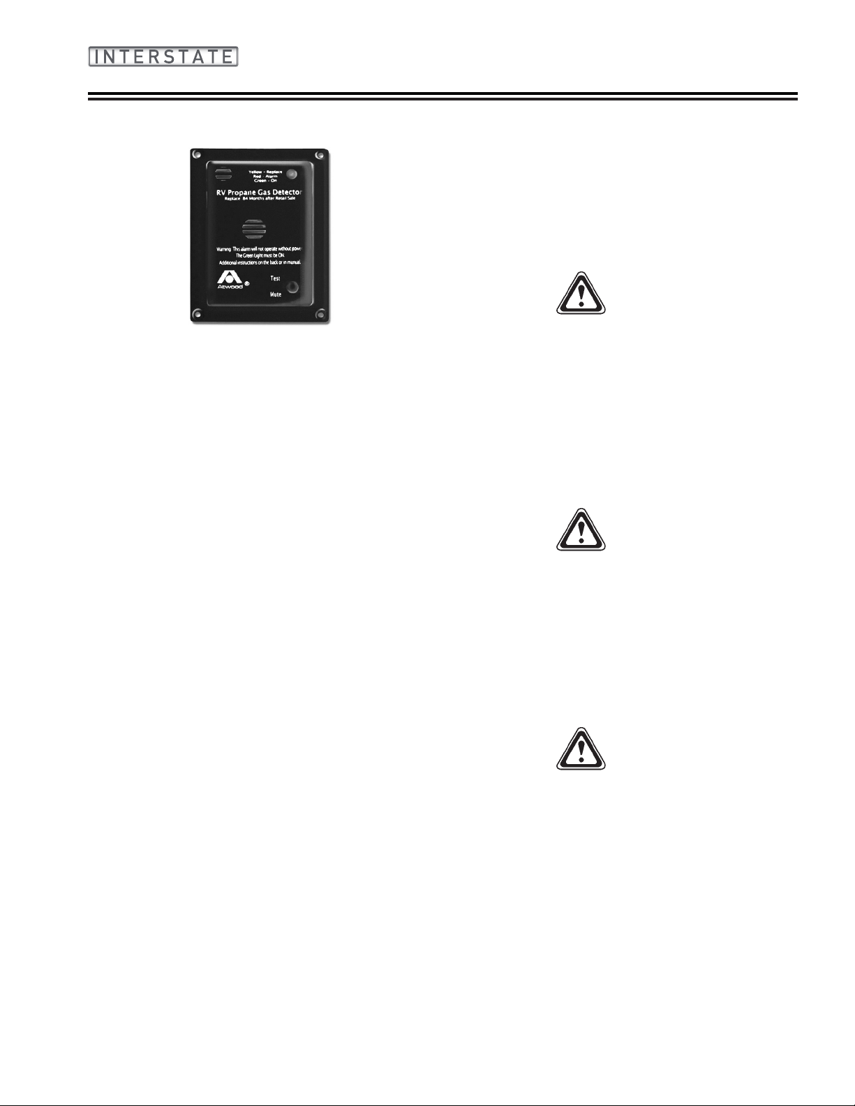
Liquid Propane Gas (LPG) Detector
This detector has a seven-year life; see end-of-life
notication in LPG detector manual. Please read the
entire detector manual before operating the unit�
The LPG detector is located in the galley area� LPG
is a mixture of gases produced and sold commercially
as a fuel for heating and cooking appliances� LPG is
highly ammable and, as a result, can be explosive if
ignited under certain circumstances� LPG is heavier
than air and, if conned in a closed space, will
accumulate close to the oor. The LPG detector is
designed to alarm at less than 25 percent of the legal
explosive limit� It will provide a visual and audible alarm
by sounding an alarm every 5 seconds and lighting the
red light emitting diode (LED)�
Your LPG detector is wired directly to your touring
coach battery and incorporates a 1-amp, in-line fuse�
It has no internal battery backup� In normal stand-by
mode, the LED indicator will be green�
Low Voltage
The operating voltage for the detector is 12 VDC� The
actual voltage supplied to the detector in a recreational
vehicle may drop below the minimum 8 VDC� The
detector provides the user with a low voltage warning
before reaching that level and will provide additional
distinct, clear warnings and alarms after the 8 VDC
level is reached� However, if available power supplied
to the unit is below the operating voltage of 8 VDC,
the detector will not detect gas or provide protection
against dangerous levels of LPG�
Detector Test
The Test/Reset button is used to verify proper alarm
function� Executing the test function sounds the alarm
and illuminates the red LED� The test will sound the
alarm twice, with 4 beeps in 1 second, followed by 5
seconds of silence� By pressing the button, you can
verify that the alarm sounds and the LED functions
properly�
WARNING
Activation of this detector indicates the possible
presence of LPG, which can cause an explosion
and/or re, causing serious injury or death. This
normally indicates a leak in the LPG installation or
an LPG appliance. Extinguish all open ames, open
your windows and door, and evacuate the unit
immediately. Do not activate any electrical switch.
Turn off the LPG using the remote shut off switch.
Do not re-enter your unit until a qualied repair
technician has corrected the problem and certied
the system as safe.
WARNING
It is not recommended that the detector be
disconnected from the battery during periods of
storage. There is a small heater on the sensor of
the device that burns away impurities in the air
during periods of normal use. During periods when
power is interrupted, impurities can build up on the
sensor. When power is returned to the detector,
the detector alarm may activate until the impurities
are burned off. This could take a number of hours,
during which time the alarm will be constantly on.
WARNING
Have a qualied technician check your LPG system
annually or if you detect any signs of leaks or
malfunctions.
NOTE
Refer to Section 5 - Interior and Section 6 -
Exterior for additional LPG warnings and safety
information.
2020 Interstate 2-7
Page 14

Safety
Basic LPG Safety Information
A warning label has been positioned in the cooking
area to remind you to provide an adequate supply of
fresh air for combustion� Unlike homes, the amount
of oxygen supply is limited due to the size of the
recreational vehicle, and proper ventilation when
using the cooking appliances will avoid dangers of
asphyxiation� It is especially important that cooking
appliances not be used for comfort heating as the
danger of asphyxiation is greater when the appliance is
used for long periods of time�
Portable fuel burning equipment, including wood and
charcoal grills and stoves, shall not be used inside
the recreational vehicle� The use of this equipment
inside the recreational vehicle may cause res or
asphyxiation�
A Warning Label has been located near the LP
gas container� This label reads: DO NOT FILL
CONTAINER(S) TO MORE THAN 80% PERCENT
OF CAPACITY. Overlling the LP gas container can
result in uncontrolled gas ow that can cause a re
or explosion. A properly lled container will contain
approximately 80 percent of its volume as liquid LP
gas�
If you smell gas
• Extinguish any open ames, pilot lights and all
smoking materials�
• Do not touch electrical switches�
• Shut off the gas supply using the remote shut off
switch�
• Open doors and other ventilating openings�
• Leave the area until odor clears�
• Have the gas system checked and leakage source
corrected before using again�
LP gas regulators must always be installed with the
diaphragm vent facing downward� Regulators that
are not in compartments have been equipped with a
protective cover� Make sure that regulator vent faces
downward and that cover is kept in place to minimize
vent blockage that could result in excessive gas
pressure causing a re or explosion.
The regulator at the LP tank is under a gray, plastic
cover� The protective cover helps to keep the vent on
the regulator from being clogged by wasps or ice, but
the regulator should be checked regularly to make sure
the vent remains clear�
WARNING
DO NOT store LP containers within vehicle. LP
containers are equipped with safety devices that
vent gas should the pressure become excessive.
WARNING
DO NOT use cooking appliances for comfort
heating. Cooking appliances need fresh air for safe
operation. Before operation, open overhead vent or
turn on exhaust fan and open window.
WARNING
Do not attempt to seal regulator cover.
WARNING
Check vent each time tank is lled to make sure it
is clear of obstructions.
WARNING
Have a qualied technician check your LP Gas
system annually or if you have any signs of leaks
or malfunctions.
2-8 2020 Interstate
Page 15
Safety
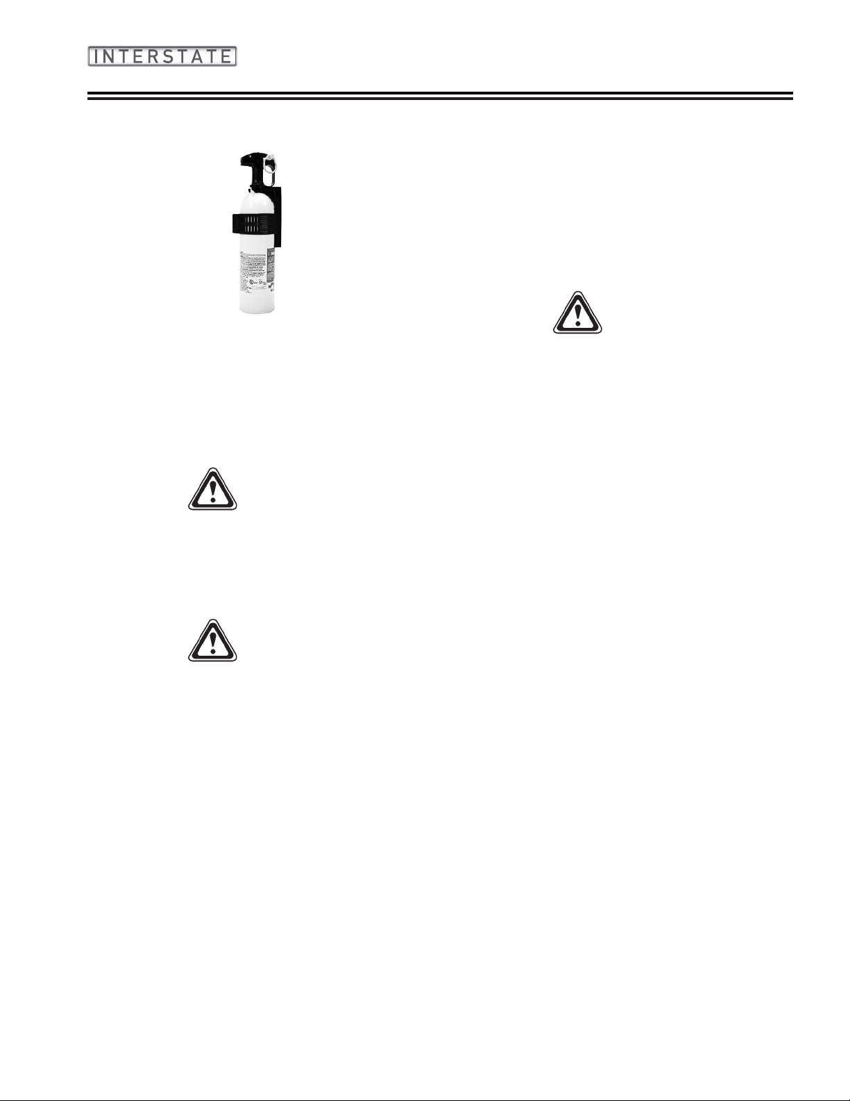
Fire Extinguisher
The re extinguisher should be checked for charge on
a regular basis� Make sure your family, especially the
cook, knows how to release the extinguisher storage
bracket and how to properly operate the extinguisher�
Check with your local re department for professional
advice on its operation and use if you nd the
directions on the extinguisher unclear� They will be able
and willing to assist you and your family�
WARNING
Read the directions carefully on the re
extinguisher. If there is any doubt on the operation
you and your family should practice, then replace
or recharge the extinguisher. You will nd your
local re department will be happy to assist you
and answer any questions.
Emergency Exit
There are three avenues of escape from the touring
coach in the event of an emergency, the driver’s door,
the passenger door, and the sliding side cargo door�
As always, safety should be one of your top priorities�
Make sure you and everyone traveling with you can
operate these doors and exit rapidly without light� A
little planning and a quick practice session at each
camping site is well worth the time it may take�
WARNING
At each campsite, make sure you have not parked
in such a manner as to block the operation of the
doors or the escape avenues by being too close to
trees, fences, or other impediments. Scenic views
are one reason for traveling, but do not park so
the beautiful lake or steep cliff is just outside your
doors. Do not block access to the doors from the
inside or outside of the vehicle.
Other safety information on the LPG system of your
touring coach is located in the Plumbing Section of this
manual�
WARNING
Do not smoke in bed. Keep matches out of reach
of small children. Do not clean with ammable
material. Keep ammable material away from open
ame. We have all heard these warnings many
times, but they are still among the leading causes
of res.
2020 Interstate 2-9
Page 16

Safety
NOTES
2020 Interstate2-10
Page 17

Section 3
GENERAL INFORMATION
GENERAL INFORMATION � � � � � � � � � � 3-1
LIMITED WARRANTY POLICY � � � � � � 3-2
This Limited Warranty Covers � � � � � � 3-2
Coverage Ends � � � � � � � � � � � � 3-2
Limitation Of Implied Warranties � � � � � 3-2
Disclaimer Of Incidental And Consequential
Damages � � � � � � � � � � � � 3-2
Repair Remedy � � � � � � � � � � � � 3-2
Back-Up Remedy � � � � � � � � � � � 3-2
What Is Not Covered � � � � � � � � � 3-3
Obtaining Warranty Service � � � � � � � 3-4
Consumer Arbitration Program � � � � � � 3-4
Events That Discharge Airstream’s
Obligations Under This Limited
Warranty � � � � � � � � � � 3-4
Airstream Limited Warranty Excludes � � � 3-4
Normal Wear � � � � � � � � � � 3-4
Accident � � � � � � � � � � � � 3-5
Abuse � � � � � � � � � � � � � 3-5
Exposure � � � � � � � � � � � � 3-5
Overload � � � � � � � � � � � � 3-5
Chemical Gassing � � � � � � � � 3-5
Sprinter Van � � � � � � � � � � � 3-5
SERVICE � � � � � � � � � � � � � � � 3-5
Reporting Safety Defects � � � � � � � � 3-6
CAMPING � � � � � � � � � � � � � � � 3-6
Suggested Pre-Travel Check List � � � � � 3-6
Interior � � � � � � � � � � � � � 3-6
Exterior � � � � � � � � � � � � � 3-6
Touring Coach Equipment
and Accessories � � � � � � � 3-6
Motoring Essentials � � � � � � � � 3-6
Overnight Stop � � � � � � � � � � � � 3-7
Overnight or Weekend Trips � � � � � � � 3-7
Longer Trips � � � � � � � � � � � � � 3-7
Extended Stay � � � � � � � � � � � � 3-7
Leveling � � � � � � � � � � � � 3-8
Effects of Prolonged Occupancy � � � � � 3-8
About Molds � � � � � � � � � � � � � 3-9
What are molds � � � � � � � � � 3-9
What factors contribute to mold growth 3-9
How can mold growth be inhibited � � 3-9
Waste Water System � � � � � � � � � � 3-9
Things Not to Put into Toilet or Drains � 3-9
Drain System (Lounge Models) � � � � � �3-10
Drain System (Grand Tour Models) � � � �3-10
Winter Traveling � � � � � � � � � � � �3-10
Heated Tanks � � � � � � � � � �3-11
Safety � � � � � � � � � � � � � � � �3-11
2020 Interstate 3-1
Page 18

General Information
Limited Warranty Policy
This Limited Warranty Covers
(i) The rst retail owner and any subsequent owners
(ii) ONLY those portions of a NEW motorhome not
excluded under the section “What is Not Covered”,
when sold by an authorized dealership and used
for its intended purpose of recreational travel and
camping; and, (iii) ONLY defects in workmanship
performed and/or materials used to assemble those
portions of your motorhome not excluded under the
section “What is Not Covered”� “Defect” means the
failure of the workmanship performed and/or materials
used to conform with the design and manufacturing
specication and tolerances of Airstream. The Limited
Warranty is transferable and the subsequent owner’s
warranty coverage period shall be the unexpired
balance of the original warranty coverage period� A
completed copy of the Warranty Transfer Form must be
submitted to Airstream at the time of resale�
When you request and accept the performance of
warranty repairs under the terms of this Limited
Warranty, you are accepting all terms of this Limited
Warranty, including by way of example, warranty
limitations and disclaimers, the forum selection clause
and the clause reducing the time period when suit must
be led for breach.
If any term of condition in this limited warranty conicts
with your state’s Uniform Commercial Code (“UCC”) as
interpreted by courts within your state, the provisions
of your state’s UCC are varied as allowed for by USS
1-302�
Coverage Ends
36 months after the rst retail owner rst takes delivery
of the motorhome from an authorized dealership or
after the odometer reaches 36,000 miles, whichever
occurs rst. Any action for breach of this warranty or
any implied warranties must be commenced not more
than 37 months after breach� Some states do not allow
the reduction of the time when a breach of warranty
claim must be commenced, so the reduction in time
when a breach of warranty claim must be commenced
may not apply to you�
Limitation Of Implied Warranties
Implied warranties arising under applicable law, if
any, including but not limited to implied warranties of
merchantability or tness for a particular purpose, are
hereby limited in duration to the term of this limited
warranty and are limited in scope of coverage to those
portions of the motorhome covered by this limited
warranty� There are no express warranties or any
implied warranties of merchantability on those portions
of the motorhome excluded from coverage� There is
no warranty of any nature made by airstream beyond
that contained in this limited warranty� No person has
authority to enlarge, amend or modify this limited
warranty� The dealer is not Airstream’s agent� Airstream
is not responsible for any undertaking, representation
or warranty made by any dealer or others beyond
those expressly set forth within this limited warranty�
Some states do not allow limitations on how long an
implied warranty lasts, so the above limitations may not
apply to you�
Disclaimer Of Incidental And Consequential Damages
Airstream disclaims any and all incidental and
consequential damages, including but not limited
to expenses such as transportation to and from
dealerships and Airstream repair facilities, loss of time,
loss of pay, loss of use, inconvenience, commercial
loss (including but not limited to lost prots), towing
charges, bus fares, vehicle rental, service call
charges, gasoline expenses, incidental charges such
as telephone calls and facsimile transmissions, and
expenses for lodging and moisture damage such
as mold and mildew as well as rust and corrosion�
This disclaimer is independent of any failure of the
essential purpose of any warranties provided with the
motorhome, and shall survive any determination that
a warranty failed of its essential purpose� Some states
do not allow the exclusion or limitation of incidental
or consequential damages, so the above limitation or
exclusion may not apply to you�
Repair Remedy
Airstream’s sole and exclusive obligation is to repair
any covered defects discovered within the warranty
coverage period if: (1) within 10 days of your discovery
of a defect you notify Airstream OR an authorized
dealership of the defect; AND (2) you deliver your
Motorhome to Airstream OR an authorized dealership
at your cost and expense�
Back-Up Remedy
If the primary repair remedy fails to successfully
cure any defect after a reasonable number of repair
attempts, your sole and exclusive remedy shall be to
have Airstream pay an independent service shop of
your choice to perform repairs to the defect OR if the
defect is incurable, have Airstream pay diminution in
value damages� The repair remedy and the back-up
3-2 2020 Interstate
Page 19

General Information
remedy must both be exhausted and these remedies
must fail to fulll their essential purpose before you can
seek any legal or equitable relief� This limited warranty
is not a warranty that promises or extends to future
performance because the warranty does not make a
representation on how your motorhome will perform in
the future but instead represents only what the remedy
will be if a defect exists�
Unless prohibited by state law, repairs will not extend
the time when you must commence a breach of
warranty claim and shall not extend the warranty
coverage period� Any performance of repairs after
the warranty coverage ends OR any performance of
repairs to those portions of your motorhome excluded
from coverage shall be considered “good will” repairs�
Warranty repairs should be expected� Airstream
may use new and/or remanufactured parts and/or
components of substantially equal quality to complete
a repair� Damage to interior or exterior surfaces, trim,
upholstery and other appearance items may occur
at the factory during assembly, during delivery of the
motorhome to your selling dealer or on the selling
dealer’s lot� Normally, any damage is detected and
corrected at the factory or by the selling dealer during
the inspection process� If you discover any damage
when you take delivery of your motorhome, you MUST
notify your dealer OR Airstream within 10 days of
the date of purchase to have damage repaired at no
cost to you� Minor adjustments, such as adjustments
to the interior or exterior doors, drawers, latches
will be performed at no cost to you by your selling
dealer during the rst 90 days of warranty coverage;
thereafter, such adjustments are your exclusive
responsibility as normal maintenance�
What Is Not Covered
1� Tires, batteries, stereo, television, range/stove,
furnace, refrigerator, air conditioner, toilet, water
heater, microwave, generator, glass breakage, and
other materials, parts and components warranted
by persons or entities other than Airstream� Please
refer to the warranties of component manufacturers
for terms and conditions of coverage;
2� Accessories and equipment that are working as
designed, but which you are unhappy because of
the design
3� Any part or component of the vehicle that was not
manufactured or installed by Airstream;
4� Normal deterioration due to wear or exposure,
including but not limited to upholstery, ooring rust,
corrosion, oxidation, and cosmetic blemishes;
5� Normal maintenance and service items, including
but not limited to light bulbs, fuses, lubricants,
sealants and seals, door adjustments, and awning
tension;
6� After-market equipment or accessories installed
on the vehicle after completion of manufacture by
Airstream, or any defects or damage caused by
such items;
7� Vehicles not purchased through an authorized
dealer of Airstream and vehicles purchased
directly or indirectly through auction, salvage,
repossession, or other non-customary sale means;
8� Any motorhome used other than for temporary
recreation purposes, including, but not limited
to, use of the motorhome for residential, rental,
business and commercial purpose or any
motorhome purchased by, registered by, or titled in
the name of a business association (such as any
LLC, corporation, or partnership)� If the motorhome
owner or user les a tax form claiming a business
or commercial tax benet or income related to
the motorhome, it shall be irrefutable that the
motorhome has been used for rental, commercial
or business purposes�
9� Defects or damage caused by, in whole or in
part, or in any way related to: Accidents, misuse
(including off-road use), or negligence; Failure
to comply with the instructions set forth in any
owner’s manual provided with the vehicle;
Alteration or modication of the vehicle except
such alterations or modications approved
in writing by Airstream; Acts of God or other
environmental conditions, such as lightning,
hail, salt causing rust, or other chemicals in the
atmosphere; De-icing agents or other chemicals
applied to the vehicle; Failure to properly maintain
or service the vehicle, including but not limited to
the maintenance of lubricants, sealants, and seals;
Condensation and the results of condensation
including water damage and the growth of mold
or mildew� Mold and mildew are natural growths
given certain environmental conditions and are not
covered by the terms of this Limited Warranty; The
addition of weight to the vehicle that causes the
total weight to exceed applicable vehicle weight
ratings, or addition of weight causing improper
distribution of the weight of the vehicle; Failure to
seek and obtain repairs in a timely manner; Failure
to use reasonable efforts to mitigate damage
caused by defects’ Failure to properly ventilate the
vehicle; Improper electric power supply or improper
2020 Interstate 3-3
Page 20

General Information
vehicle hookup to other facilities; and, Acts or
omissions of any person or entity other than
Airstream� (Note: An irrefutable presumption arises
that the motorhome has been used for commercial
and/or business purposes if the motorhome owner
or user les a tax form claiming any business or
commercial tax benet related to the motorhome,
or if the motorhome is purchased, registered or
titled in a business name�)
Obtaining Warranty Service
In order to obtain warranty service under this Limited
Warranty, the owner must do all of the following:
1� Owner and dealer representative must complete
and return the Customer Performance Checkout
within 10 days from delivery of the vehicle,
2� Notify Airstream or one of its authorized,
independent dealers of any claimed defect within
the warranty period or 10 days thereafter,
3� Provide notication of a defect within 10 days of
discovery of that defect, and
4� Promptly return the motorhome to an authorized
Airstream dealer or Airstream for repairs�
If you believe a defect covered by this Limited Warranty
still exists after an attempted repair by an authorized
Airstream dealer, you must contact Airstream at the
following address, specifying:
1� The complete serial number of the motorhome,
2� The date of original purchase and the date of
original delivery,
3� The name of the selling dealer, and
4� The nature of the problem and the steps or service
which have been performed�
Airstream, INC�
428 West Pike Street
P�O� Box 629
Jackson Center, Ohio 45334-0629
Attention: Owner Relations Department
Airstream may direct you to an authorized Airstream
dealer, or may request that you bring your motorhome
to the Airstream factory in Jackson Center, Ohio for
repairs�
Airstream does not control the scheduling of repairs
at its authorized Airstream dealers, and repairs at the
Airstream factory may not be immediately available�
Therefore, you may encounter delays in scheduling
repairs and/or completion of repairs� All costs
associated with transporting the motorhome for any
warranty service shall be the sole responsibility of the
owner�
Consumer Arbitration Program
For recreation vehicles purchased in the State of
California, Airstream, Inc� participates in the Consumer
Arbitration Program for Recreation Vehicles (CAP-RV)�
This third-party dispute resolution program is available,
at no charge to you, to settle unresolved warranty
disputes for recreation vehicles� This dispute resolution
program reviews eligible product and service related
complaints involving warranty covered components�
To nd out more about this program, or to request
an application/brochure, please call the Arbitration
Administration ofce toll-free 800.279.5343. The CAPRV program operates as a certied mechanism under
the review of the California Arbitration Certication
Program� Members of the armed forces who purchased
the vehicle in California, or who were stationed in
or a resident of California at the time of purchase
(regardless of state of purchase) or who are stationed
in California at the time of application to this program
may utilize the CAP-RV program�
Events That Discharge Airstream’s Obligations Under This Limited Warranty
Misuse or neglect, accidents, unauthorized alteration,
failure to provide reasonable and necessary
maintenance (see Owner’s Manual), damage caused
by off road use, collision, re, theft, vandalism,
explosions, overloading in excess of rated capacities,
odometer tampering, and use of the motorhome
for commercial, business, or rental purposes shall
discharge Airstream from any express or implied
warranty obligation to repair any resulting defect�
Airstream Limited Warranty Excludes
Normal Wear
Items such as curtains, upholstery, oor coverings,
and window, door, and vent seals will show wear or
may even wear out within the 3-year warranty period,
depending upon the amount of usage, weather, and
atmospheric conditions�
3-4 2020 Interstate
Page 21

General Information
Accident
We strongly urge our dealers and customers to inspect
the touring coach upon receipt of delivery for any
damage caused by accident while being delivered to
the dealer, or while it is on the dealer’s lot� Damage
of this nature becomes the dealer or customer’s
responsibility upon acceptance of delivery, unless
Airstream is notied and the person making the
delivery veries the damage. Glass breakage, whether
obviously struck or mysterious, is always accidental
and covered by most insurance policies�
Abuse
Lack of customer care and/or improper maintenance
will result in early failure for which Airstream cannot be
held responsible�
Exposure
Deterioration by sunlight is possible to such items as
tires, curtains or upholstery� Steel or metal surfaces are
subject to the elements, causing rust and corrosion that
is normal and beyond the control and responsibility of
Airstream�
Overload
Overload Damage due to loading beyond capacity
or to cause improper balance is not covered by the
Airstream Limited Warranty� The Airstream Touring
Coach is engineered to properly handle any normal
load� There are limits to the amount of load that can
be safely transported depending upon speed and road
conditions� If these limits have been exceeded, the
Airstream Limited Warranty will not cover resulting
damage� For additional information on the load
capacity of your touring coach, consult your Sprinter
and Airstream Owner’s Manuals or gross vehicle
weight rating plate�
Chemical Gassing
Chemical gassing is not a “Defect” in your recreational
vehicle and is not covered by the Limited Warranty�
Please follow the recommendations in this manual to
address this concern�
Sprinter Van
Airstream, Inc�, does not accept any responsibility
in connection with any of its touring coach’s for the
Sprinter Van or its components� The Sprinter Van
and its components are covered by Mercedes-Benz
Warranties as explained by Sprinter literature provided�
Your Sprinter Van and its components are pre-checked
by its manufacturer before delivery to Airstream� All
service to the Sprinter Van and its components must
be performed by Mercedes-Benz Sprinter designated
service points according to the manufacturer’s warranty
and service policies� The literature provided with each
touring coach gives important information concerning
its warranty coverage, maintenance, and operation�
The Airstream Interstate Owner’s Manual may provide
additional information and tips on the use of the van as
a touring coach, however, no information, in whole or in
part, in any Airstream manual should be interpreted as
advice or directions to disregard or void the Warnings,
Cautions, Notices, or other information contained in the
Sprinter’s manuals�
WARNING
Your Mercedes-Benz Sprinter Van Operator’s and
Warranty Manuals contain important cautions,
warnings, operational, and warranty information on
the Sprinter and its components. All information
in the Sprinter manual should be reviewed and
followed for your safety.
Service
Before leaving the factory, every vital part of the touring
coach is tested for performance� Each test is signed
and certied by an inspector. After the touring coach
arrives on your dealer’s lot, all vital parts and systems
are again tested� When you take delivery of your new
touring coach, you will receive a complete check out�
At that time, a specied list of performance checks on
your touring coach equipment will be conducted, and
any deciencies you have experienced since taking
delivery will be corrected�
Please contact your dealer if your touring coach needs
service� Major service under your Airstream Limited
Warranty is available through our nationwide network
of Airstream Dealer Service Centers� An up-to-date
list of Dealer Service Centers will be sent to you with
an Owner’s Survey shortly after your touring coach is
delivered� Our website, www�Airstream�com also has a
dealer locator on it� This list is current as of the date of
this publication�
Occasionally, dealerships change or new dealers are
added who may not appear on this list� For this reason,
it is suggested you contact your local dealer from
time to time for an updated list� Additional copies are
available if you need them� All centers operate on an
appointment basis for the utmost efciency.
2020 Interstate 3-5
Page 22

General Information
When you require service for your touring coach from
the Airstream Factory Service Center or a Certied
Dealer Service Center, please contact the service
manager for an appointment, and inform them if you
are unable to keep the appointment date or wish to
change it� Service may be arranged at the Factory
Service Center by contacting the Service Coordinator
at:
Airstream Factory Service Center
428 West Pike Street
P�O� Box 629
Jackson Center, Ohio 45334-0629
Phone: (937) 596-6111 or (877) 596-6111
Reporting Safety Defects
If you believe your vehicle has a defect which could
cause a crash or could cause injury or death, you
should immediately inform the National Highway Trafc
Safety Administration (NHTSA), in addition to notifying
Airstream, Inc�
If NHTSA receives similar complaints, it may open an
investigation, and if it nds that a safety defect exists
in a group of vehicles, it may order a recall and remedy
campaign� However, NHTSA cannot become involved
in individual problems between you, your dealer, or
Airstream Inc�
To contact NHTSA, you may either call the Vehicle
Safety Hotline toll-free at 1-888-327-4236 (TTY: 1-800424-9153), go to http://www�safercar�gov, or write to:
Administrator
NHTSA
1200 New Jersey Avenue, S�E�
Washington, DC 20590
You can also obtain other information about motor
vehicle safety from http://www�safercar�gov�
6� Hold down or securely stack all loose, hard, and
sharp objects�
7� Drain toilet bowl�
8� Turn off interior lights�
Exterior
1� Disconnect and stow electrical hookup cord�
2� Check exterior lighting�
3� Check torque of lug nuts�
4� Check tires for correct pressure�
5� Adjust vehicle mirrors�
6� Pull forward about 50 ft, test brakes, and check site
for forgotten objects and cleanliness�
Touring Coach Equipment and Accessories
1� Water hose, 5/8-in� high-pressure, tasteless,
odorless, non-toxic (two 25-ft� sections)�
2� Y connection - water hose�
3� Holding tank cleaner and deodorizer�
4� Power cord adapter, 30-amp capacity�
5� 30-ft� electric cord, 30-amp capacity�
6� Wheel chocks�
7� Torque wrench�
8� Quality tire gauge�
9� Verify emergency light kit and is operational�
(Found in driver’s door�)
Motoring Essentials
1� Touring coach registration�
2� Carry driver’s license�
3� In Canada, bring along a non-residence liability
insurance card and your passport�
4� In Mexico, you must have special auto insurance�
Camping
Suggested Pre-Travel Check List
Interior
1� Turn off water pump switch�
2� Close windows and vents�
3� Close all interior cabinet doors�
4� Latch refrigerator door. (Seal containers rst.)
5� Latch microwave�
5� Carry an extra set of the ignition keys in a separate
pocket or in your wallet�
6� Keep an operating ashlight with fresh batteries in
the glove compartment�
7� Pack the trunk so that you can reach the tools and
spare tire without completely unpacking�
3-6 2020 Interstate
Page 23

General Information
8� Keep sharp or hard articles securely packed�
9� Do not pack things in the passenger seating area�
You will need the maximum space for comfort�
10� Wear easy wash, drip-dry traveling clothes�
11� Do not make your vacation trips a mileage
marathon� Stop and relax frequently�
12� Verify rst aid kit provided in passenger door is
complete and up to date�
13� Carry your pet’s dish, food, leash, and health and
registration papers�
Overnight Stop
In time you will develop a knack for spotting wonderful
little roadside locations by turning off the main highway
and exploring� There are many modern recreational
vehicle parks, including State, County, and Federal
parks with good facilities, where you may obtain
electrical, water, and sewer hookups and connections�
Directories are published which describe in detail these
parks and tell what is available in the way of services
and hookups�
All you need to do to enjoy the self-contained luxury is
to:
1� Turn on LP gas supply and light appliance pilots if
required�
2� Turn on water pump and open faucets until air is
expelled from the system�
Before moving on, turn off the LP gas and water pump�
Check your campsite, both for cleanliness and to be
sure you have not left anything behind� Make sure
everything is properly stowed�
Overnight or Weekend Trips
On overnight or weekend trips, chances are you will
not use up the capacity of the holding tanks� Deplete
the water supply if using the system moderately or
conservatively� You will need to maintain the level of
your battery during this time� If your battery falls to 60
percent capacity, charge the battery by starting your
generator�
WARNING
Frequently depleting the battery below 60%
capacity will shorten its lifespan.
Longer Trips
On a longer trip, when you have stayed where sewer
connections and utility hookups were not available, it
will be necessary for you to stop from time to time to
dispose of the waste in the holding tank and replenish
the water supply� Many truck stops and gas stations,
chain and individually owned, have installed sanitary
dumping stations for just this purpose� Booklets are
available that list these facilities�
When you stop for the night, your Airstream Touring
Coach is built to be safely parked in any spot that
is relatively level and where the ground is rm. Your
facilities are with you� You are self-contained� Try to
pick as level a parking spot as possible�
Extended Stay
Making a long trip is not very different from making
a weekend excursion� Since everything you need is
right at hand, you are at home wherever you go� When
packing for an extended trip, take everything you need,
but only what you need�
Hook up to water by attaching a ½ -inch minimum highpressure water hose to the city water service�
Plug the 120-volt, 30-amp Electrical Cable into the City
Power Service� Be sure you have the wire grounded
and have the proper polarity�
To use the generator, you simply start it� All switching is
done automatically� The generator can be started from
any of the Multiplex Systems control panels� It is easier
on your generator and appliances if you’ll allow the
generator to reach its normal operating speed (about a
minute) prior to applying heavy current loads�
Your Touring Coach is equipped with an Automatic
Generator Start System (AGS)� The purpose of an
AGS system is to automatically start (and run) the
generator when the 12 volt electrical system (house
batteries) drops to a pre-determined level� See Section
5 for more information on the AGS System�
A Cable/Satellite TV connection is located in the
exterior compartment along with the switches for the
dump valves, macerator pump, and macerator pump
high-pressure hose reel�
Turn on the gas supply� Lighting a top range burner
to bleed any air from the system will make it easier to
start other appliances including the furnace�
When you stay for extended periods where electric
or water hookups are not available, you must make
regular checks on the condition of your 12-volt battery
2020 Interstate 3-7
Page 24

General Information
and the contents of your water tank (Multiplex control
panel or SeeLevel II Monitor Panel)� Carry drinking
water in a clean bucket to rell your tank. When your
waste tank nears capacity, move your touring coach to
a dumping location�
Leveling
When you plan to stay in the same place for several
days, weeks, or months, you will want your touring
coach to be as level as possible� Check the attitude
with a small spirit level set on the inside work counter� If
a correction is necessary, then you must rst level from
side to side� This can be done most easily by driving up
a small ramp consisting of 2 in� x 6 in� boards tapered
at both ends� Airstream does not recommend placing
tires in a hole for leveling� Refer to Section 7 - Sprinter
Van for more information on tires�
For units equipped with the optional hydraulic leveling
system refer to Section 6 - Hydraulic Leveling System
for more information�
Effects of Prolonged Occupancy
Your touring coach was designed primarily for
recreational use and short-term occupancy� If you
expect to occupy the touring coach for an extended
period, be prepared to deal with condensation and
the humid conditions that may be encountered� The
relatively small volume and tight compact construction
of modern recreation vehicles mean that the normal
living activities of even a few occupants will lead to
rapid moisture saturation of the air contained in the
touring coach and the appearance of visible moisture,
especially in cold weather�
Just as moisture collects on the outside of a glass
of cold water during humid weather, moisture can
condense on the inside surfaces of the touring coach
during cold weather when relative humidity of the
interior air is high� This condition is increased because
the insulated walls of a recreation vehicle are much
thinner than house walls� Estimates indicate that two
adults can vaporize up to one-and-a-half gallons of
water daily through breathing, cooking, bathing, and
washing� Unless the water vapor is carried outside
by ventilation or condensed by a dehumidier, it will
condense on the inside of the windows and walls as
moisture, or in cold weather as frost or ice� It may also
condense out of sight within the walls or the ceiling
where it will manifest itself as warped or stained
panels� Appearance of these conditions may indicate
a serious condensation problem� When you recognize
the signs of excessive moisture and condensation in
the touring coach, action should be taken to minimize
their effects�
NOTE
Your touring coach is not designed, nor intended,
for permanent housing. Use of this product for
long term or permanent occupancy may lead
to premature deterioration of structure, interior
nishes, fabrics, carpeting, and drapes. Damage or
deterioration due to long-term occupancy may not
be considered normal, and may under the terms of
the warranty constitute misuse, abuse, or neglect,
and may therefore reduce the warranty protection.
To avoid condensation problems, try to follow these tips
to help alleviate excess moisture:
Allow excess moisture to escape to the outside when
bathing, washing dishes, hair drying, laundering, and
using appliances and non-vented gas burners� Always
use an exhaust fan when cooking�
Keep the bathroom door closed and the vent or window
open when bathing and for a period of time after you
have nished.
If you are experiencing condensation, you may want to
reconsider hanging wet clothes in the touring coach to
dry�
In hot weather, start the AC early as it removes excess
humidity from the air while lowering the temperature�
Keep the temperature as reasonably cool during cold
weather as possible� The warmer the vehicle, the
more cold exterior temperatures and warm interior
temperatures will collide on wall surfaces, thus creating
condensation�
Use the ceiling vent to keep air circulating inside the
vehicle so condensation and mildew cannot form in
dead air spaces� Allow air to circulate inside closets
and cabinets (leave doors partially open)� Please
keep in mind that a closed cabinet full of stored goods
prevents circulation and allows the exterior temperature
to cause condensation�
The natural tendency would be to close the vehicle
tightly during cold weather� This will actually compound
the problem� Simply put, you need to remove some
3-8 2020 Interstate
Page 25

General Information
of the warm air and allow some cool outside air to get
inside the vehicle so the furnace will not recycle the
humid interior air�
Minimize the use of incandescent lights, which produce
heat and contribute to condensation�
About Molds
What are molds
Molds are microscopic organisms that naturally
occur in virtually every environment, indoors and
out� Outdoors, mold growth is important in the
decomposition of plants� Indoors, mold growth is
unfavorable� Left unchecked, molds break down
natural materials, such as wood products and fabrics�
Knowing the potential risks is important for any type of
homeowner to protect their investment�
What factors contribute to mold growth
For mold growth to occur, temperatures, indoor or
outdoors, must be between 40°F and 100°F and also,
there must be a source of moisture, such as humidity,
standing water, damp materials, etc� Indoors, the most
rapid growth occurs with warm and humid conditions�
How can mold growth be inhibited
By controlling relative humidity, the growth of mold
and mildew can be inhibited� In warm climates, use
of the air conditioner will reduce the relative humidity�
Vents are located in the bathing and cooking areas
and constant use is advised during food preparation
and bathing, even during colder weather� Additionally,
opening a window during these activities will assist in
ventilation� In extremely humid conditions, the use of
a dehumidier can be helpful. If using a dehumidier,
please read and follow all manufacturer instructions
and recommendations to the use and cleaning of the
dehumidier.
Waste Water System
The main parts of the waste water system are the
toilet, dual holding tanks, and tank dump valves (see
Section 9 - Maintenance for dump valve information)�
The system is designed to provide complete selfcontained toilet facilities, while on the road or parked,
without being connected to a sewage line� It may also
be used when parked while connected to a sewage
hose�
Keep the dump valves closed with either method and
empty the tanks when they are nearly full� The idea is
to send a large volume of water through the tanks and
hose at the same time to oat solids away.
After the sewage tank has been emptied, close the
gate valves and put approximately 5 gallons of water
in the sewage holding tank using the black tank ush
inlet� This will spray the interior of the tank with water
and help prevent solids from building up in the sewage
holding tank� The addition of a deodorizing agent like
Aqua-Kem will help prevent odors�
Should you ever have a buildup of solids, close the
valves, ll the tanks about 3/4 full with fresh water,
drive a distance to agitate the solids, and drain the
tanks�
Things Not to Put into Toilet or Drains
• Facial tissues (they do not dissolve like toilet paper)�
• Automotive antifreeze, ammonia, alcohols, or
acetone�
• Table scraps or other solids that may clog the drains�
Frequent use of your touring coach or cleaning
regularly is an important preventive measure� Further,
any spills should be wiped up quickly and dried as soon
as possible� Avoid leaving damp items lying about�
On safe surfaces, use mold or mildew killing cleaning
products� Check sealants regularly, and reseal when
necessary to avoid water leaks� Proper preventive
maintenance to the touring coach and its accessories,
as described both in this manual and in accompanying
literature, will provide the best protection to the touring
coach�
2020 Interstate 3-9
Page 26
General Information
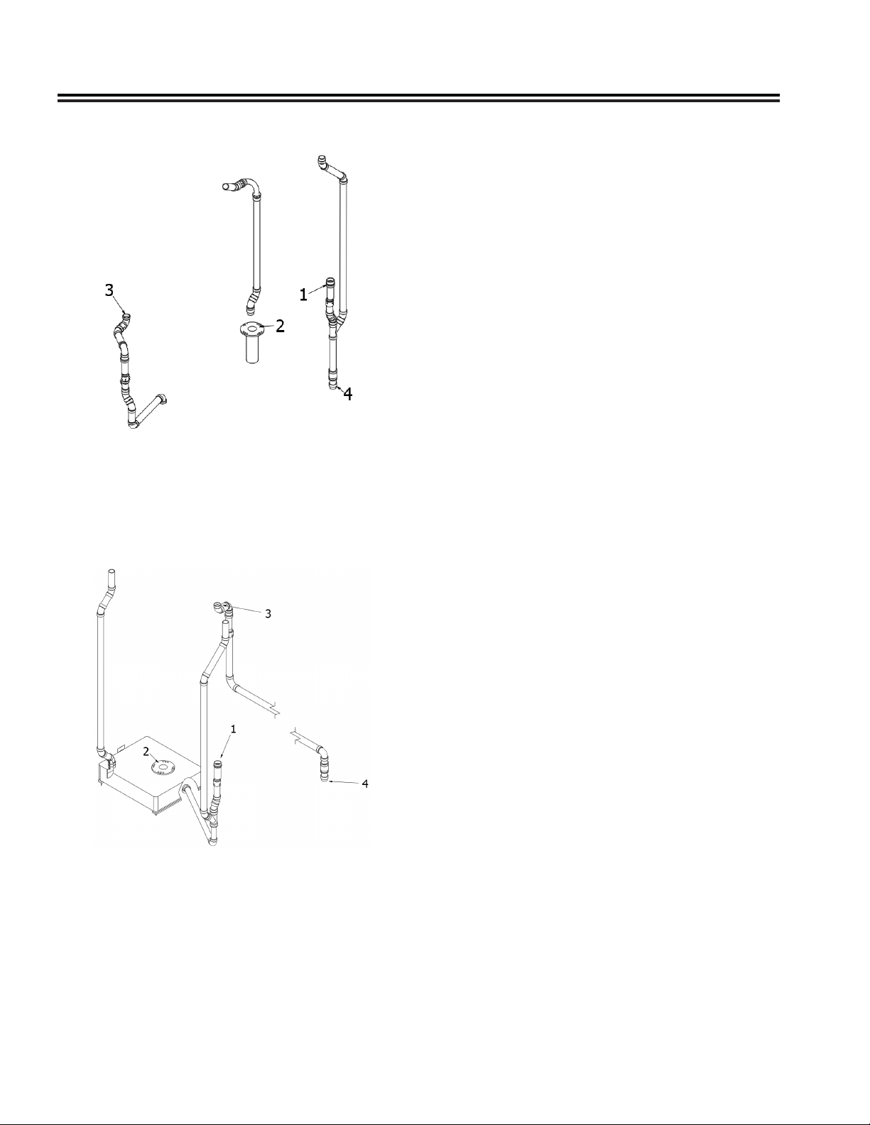
Drain System (Lounge Models)
1� Lavatory Drain
2� Black Water Tank (Toilet)
3� Galley Drain
4� Gray Water Tank
Drain System (Grand Tour Models)
Winter Traveling
Traveling in sub-freezing temperatures will require
certain precautions to protect the plumbing system
and your personal belongings from being damaged by
freezing�
Some states do not allow LPG to be turned on while
moving� While traveling in these states, simply use
your common sense� How cold is it? How long will
it be before you can turn the heat back on? Is the
temperature dropping or rising? Remember, when
driving at 50 MPH, the wind chill factor will cause the
interior of the touring coach to cool much faster than a
touring coach that is parked�
1� You must have a plentiful supply of propane gas as
the heat from the furnace warms the touring coach
and keeps the fresh water lines and black water
holding tank from freezing�
2� If your stay is longer than overnight, you should
endeavor to have 120-volt electricity available� The
house battery, fully charged, will not last more than
about 15 hours in freezing weather, less (4 hours)
with use of the tank heating pads� Of course, you
can run your generator to recharge the battery, or
even use the generator continually� Keep an eye
on your LP Gas or engine fuel according to the
type of generator your touring coach is equipped
with� Since the generator starts off the house
battery, it is recommended to start the generator
prior to running the battery down�
1� Lavatory Drain
2� Black Water Tank (Toilet)
3� Galley Drain
4� Gray Water Tank
3� Minimize use of electricity if 120-volt power source
is not available�
4� Leave cabinet doors, wet bath doors, and
wardrobe doors slightly open at night to allow
circulation of air in and around all components�
5� Save 12-volt power by using non-toxic RV-
approved antifreeze in gray water holding tank
instead of heating pad to prevent freezing� Quantity
of antifreeze needed will vary with ambient
temperature and the amount of liquids in tank�
6� For extended stays in cold weather, insulate all
water lines outside the touring coach� You should
remember that low temperatures in combination
with high winds cause an equivalent chill
temperature much below what your thermometer is
reading� For instance, with an outside temperature
of zero degrees, and the wind velocity of 10 miles
per hour, the equivalent chill temperature is -20°F�
7� Remember to remove and drain the exterior
shower faucet to prevent freeze damage�
3-10 2020 Interstate
Page 27
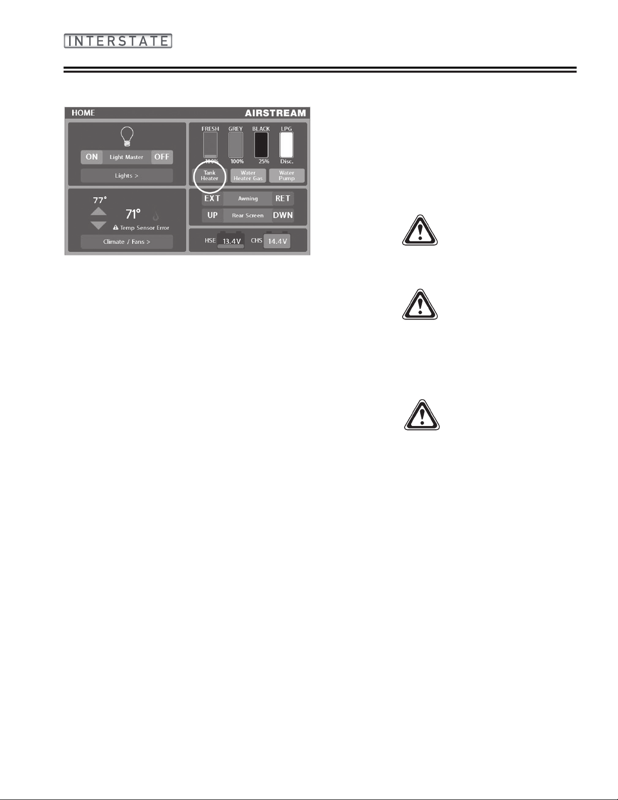
General Information
Heated Tanks
The Interstate Touring Coach has 12-volt heat pads
installed with the fresh and gray water tanks to help
prevent freezing� The tank pads are controlled by either
of the touch screen Multiplex control panels located in
the front or rear of the touring coach� When the outside
temperature is near freezing, simply switch “ON” the
holding tank heaters� Built-in sensors will activate the
heat pads when the contents of the tanks drop to 44°F�
Once the liquid is heated and rises to 64°F the heat
pads will automatically deactivate� Switch the power
“OFF” when the ambient outside temperature remains
above freezing or if the tanks are empty� Battery power
will last about 4 hours unless the unit is plugged into
an external AC power source or the generator is ran
to operate the inverter/charger� To conserve battery
power, RV antifreeze may be used to protect the gray
and black tanks�
NOTE
The black tank is installed above the oor where
heat from the furnace will keep it from freezing.
NOTE
Drain and winterize all models if the water systems
are not being used during winter traveling. Refer
to Section 9 - Maintenance in this manual for
winterizing instructions.
Safety
As always, safety should be a top priority� Ensure
that you, and everyone traveling with you, can quickly
operate the main door and the emergency exit window
in the dark� Plan for other means of escape in case
these designated exits are blocked�
The escape windows(s) are identied by their red
release handles� To release the escape windows, lift up
on both latches, push on the glass, and swing it clear�
WARNING
The window operation should be checked before
each trip and the latches lubricated with silicon
spray or an equivalent lubricant every 3 months.
WARNING
Read the directions on the re extinguisher
carefully. If you have any doubts as to its
operation, you and your family should practice,
and then replace or recharge the extinguisher. Your
local re department will be able to assist you and
answer any questions.
WARNING
Do not smoke inside the touring coach. Keep
matches out of reach of small children. Do not
clean with ammable material. Keep ammable
material away from open ame. Always shut off the
LP gas at the bottles when fueling a tow vehicle.
We have all heard the above warnings many times,
yet the situations or occurrences they discuss are still
among the leading causes of res.
Safety information concerning the LPG system of your
touring coach is located in Section 6 - Exterior of this
manual�
2020 Interstate 3-11
Page 28

General Information
NOTES
2020 Interstate3-12
Page 29

Section 4
FLOOR PLANS AND
SPECIFICATIONS
FLOOR PLANS � � � � � � � � � � � � � � � � � � � � � � � � � � � � � � 4-2
Interstate Lounge � � � � � � � � � � � � � � � � � � � � � � � � � � � � 4-2
Interstate Grand Tour � � � � � � � � � � � � � � � � � � � � � � � � � � � 4-2
SPECIFICATIONS � � � � � � � � � � � � � � � � � � � � � � � � � � � � 4-3
Specication Chart � � � � � � � � � � � � � � � � � � � � � � � � � � � � 4-3
Specication Tags � � � � � � � � � � � � � � � � � � � � � � � � � � � � 4-4
Tire Size with Maximum Ination Pressure Cold � � � � � � � � � � � � � � � � 4-4
2020 Interstate 4-1
Page 30

Floor Plans And Specications
Floor Plans
Interstate Lounge
Interstate Grand Tour
4-2 2020 Interstate
Page 31

Floor Plans And Specications
Specications
Specication Chart
NOTE
All weights listed in the Specication Chart are checked and updated throughout the model year.
Your production coach may vary from weights listed.
Interstate Series
Model All Models 4 x 4 Option
Chassis Mercedes-Benz® Sprinter 3500 Extended Mercedes-Benz® Sprinter 3500 Extended
Engine Mercedes-Benz® 3.0L V6 Turbo Diesel Mercedes-Benz® 3.0L V6 Turbo Diesel
Emissions
Horsepower/Torque 188 HP/325 lbs Torque 188 HP/325 lbs Torque
Transmission 7 Speed Automatic 7 Speed Automatic
Axle Ratio 3�92 3�92
Wheelbase 170” 170”
MPG* 18+ Estimated Highway 18+ Estimated Highway
Exterior Overall Length 24’ 4.5” 24’ 4.5”
Exterior Overall Height 9’ 7” (with Antenna) 9’ 9” (with Antenna)
Exterior Overall Width 6’ 7.5” 6’ 7.5”
Interior Height 6’ 2.25” 6’ 2.25”
Interior Width 5’ 10” 5’ 10”
GVWR 11,030 lbs 11,030 lbs
GCWR 15,250 lbs 15,250 lbs
UBW (Lounge) 9,434 lbs 9,773 lbs
UBW (GT Lounge) 9,369 lbs 9,769 lbs
NCC (Lounge) 1,596 lbs 1,257 lbs
NCC (GT Lounge) 1,661 lbs 1,261 lbs
Tow Capacity Up To 5,000 lbs Up To 5,000 lbs
Fuel Tank 24.5 gallon 24.5 gallon
Fresh Water Capacity 27 gallon 27 gallon
Gray Water Tank 21 gallon 21 gallon
Black Water Tank 11 gallon (GT 13 gallon) 11 gallon (GT 13 gallon)
LPG 14.55 gallon 14.55 gallon
Water Heater (Combination Electric & LPG) 60,000 BTU On-Demand 60,000 BTU On-Demand
Air conditioner 13,500 BTU 13,500 BTU
Refrigerator w/Freezer Box (Lounge)
Refrigerator & Freezer (GT)
Generator (LPG) w/Autogen Start 2.5 kW 2.5 kW
Front and Rear Parking Sensors Standard Standard
Mercedes-Benz® Warranty 3 Years/36,000 Miles 3 Years/36,000 Miles
Mercedes-Benz® Engine Warranty 5 Years/100,000 Miles 5 Years/100,000 Miles
Furnace 16,000 BTU 16,000 BTU
(12 Volt & 120 Volt)
(120 Volt)
Microwave 1.2 cubic feet 1.2 cubic feet
Cooktop 2 Burner with Integrated Cover 2 Burner with Integrated Cover
Batteries (Coach)
Converter/Inverter 50-Amp Charger, 1,000 Watt Inverter 50-Amp Charger, 1,000 Watt Inverter
Shore Power 30-Amp/120-Volt Service 30-Amp/120-Volt Service
Solar Power 300 Watt (3 - 100 Watt Panels) 300 Watt (3 - 100 Watt Panels)
Bed Size (Lounge) 70” X 82” 70” X 82”
Airstream Warranty 3 Years/36,000 Miles 3 Years/36,000 Miles
BlueTEC SCR Technology, 50 States - EPA/
CARB Standards
3.1 cubic feet 3.1 cubic feet
5.0 cubic feet (Fridge)
1.6 cubic feet (Freezer)
(4) Deep Cycle Maintenance Free Group 24
AGM
BlueTEC SCR Technology, 50 States - EPA/
CARB Standards
5.0 cubic feet (Fridge)
1.6 cubic feet (Freezer)
(4) Deep Cycle Maintenance Free Group 24
AGM
2020 Interstate 4-3
Page 32

Floor Plans And Specications
The Unit Base Weight (UBW) and Net Carrying
Capacity (NCC) weights listed in the Specication
Chart are for the base unit with LP and batteries
included.
Gross Vehicular Weight Rating (GVWR) is the
maximum permissible weight of this touring coach
when fully loaded. It includes all weight at the touring
coach axle(s).
UBW is the dry weight of the base unit without options.
NCC is equal to GVWR minus UBW. Gross Axle
Weight Rating (GAWR) is the value specied as the
load carrying capacity of a single axle system, as
measured at the tire-ground interfaces.
Specication Tags
For precise cargo capacity, refer to the Cargo-Carrying
Capacity tag on the inside of the door. The WEIGHT
OF CARGO SHOULD NEVER EXCEED numbers
shown on the tag, which is the maximum weight of
cargo you can load and carry in your specic touring
coach as built with its options.
Located on the front roadside of your touring coach are
the Tire and Loading, and Vehicle Manufacturing tags.
The Vehicle Manufacturing tag lists the size of tires
and wheel rims, maximum cold ination pressures, the
Vehicle Identication Number (VIN), and GAWR.
For a complete list of capacities, see the Specications
Chart on the previous page.
The Tire and Loading information tag lists the Size and
Cold Ination Pressure of the tires on your vehicle, the
weight of your touring coach as manufactured, and the
GVWR.
Tire Size with Maximum Ination Pressure
Cold
• LT 215/85R16 - 61 psi
WARNING
For safety reasons, the wheel tightening torque
must be checked immediately after changing a tire
and again after 30 miles to 140 ft-lbs. The wheels
could otherwise come loose.
4-4 2020 Interstate
Page 33

Section 5
INTERIOR
INTERIOR � � � � � � � � � � � � � � � � 5-1
GENERAL INFORMATION AND CLEANING � 5-3
Ultra Leather � � � � � � � � � � � � � 5-3
Wall Fabric, PermaBlok3® � � � � � � � � 5-3
Cabinets and Overhead Lockers � � � � � 5-3
Aluminum Interior Roof Skin � � � � � � � 5-3
Counter Area � � � � � � � � � � � � � 5-3
Sinks � � � � � � � � � � � � � � � � 5-4
Vinyl Flooring � � � � � � � � � � � � � 5-4
General Cleaning � � � � � � � � � 5-4
Polishing the Flooring � � � � � � � 5-4
Wet Bath � � � � � � � � � � � � � � 5-4
Telephone Shower Head � � � � � � 5-4
Retractable Clothesline � � � � � � 5-4
Toilet � � � � � � � � � � � � � � � � 5-4
Deodorizers � � � � � � � � � � � 5-5
Faucets � � � � � � � � � � � � � � � 5-5
ELECTRICAL � � � � � � � � � � � � � 5-7
12-Volt System � � � � � � � � � � � � 5-7
12-Volt Operation � � � � � � � � � 5-8
Multiplex System � � � � � � � � � � � 5-8
Systems Controlled By Firey � � � � 5-8
Ceiling and Directional Lighting � � � 5-9
120-Volt Power � � � � � � � � � � � � 5-9
Power Center � � � � � � � � � � � � �5-10
Auxiliary Fuse Locations � � � � � �5-10
Energy Management System (EMS) � � � �5-10
Circuit Protection � � � � � � � � �5-10
Operation � � � � � � � � � � � �5-11
Display Panel � � � � � � � � � � � � � 5-11
Service � � � � � � � � � � � � �5-11
Status � � � � � � � � � � � � �5-11
Automatic Generator Start (AGS) � � � � �5-12
Automatic Switch Over Box � � � � � � �5-12
Lavatory Faucet � � � � � � � � � 5-5
Galley Faucet � � � � � � � � � � 5-5
Faucet Cleaning and Care � � � � � 5-5
Driver and Passenger Seats � � � � � � � 5-5
Captain’s Chairs, Second Row � � � � � � 5-5
Rear Lounge/Bed � � � � � � � � � � � 5-6
Pedestal Table � � � � � � � � � � � � 5-6
Collapsing Clothes Rod � � � � � � � � � 5-6
Privacy Sun Shades � � � � � � � � � � 5-7
Power Shades � � � � � � � � � � � � 5-7
Storage Tips � � � � � � � � � � � � � 5-7
2020 Interstate 5-1
Generator/City Power � � � � � � �5-13
Battery Disconnect Switches � � � � � � �5-13
Manual Disconnect Switch � � � � �5-13
Multiplex System Disconnect Switch �5-13
Battery Separator � � � � � � � � � � �5-14
Protecting the Charging System � � �5-14
Monitor Panel � � � � � � � � � � � � �5-14
Inverter/Charger � � � � � � � � � � � �5-14
Converter � � � � � � � � � � � �5-15
120-Volt Electrical System � � � � � � �5-15
City Power � � � � � � � � � � �5-15
Ground Fault Circuit Interrupter � � �5-15
GFCI Breaker Test � � � � � � � �5-16
Page 34

Interior
Section 5
Interior
ENTERTAINMENT SYSTEMS � � � � � � �5-16
TV Antenna � � � � � � � � � � � � �5-16
Cleaning Antenna Housing � � � � �5-16
TV � � � � � � � � � � � � � � � � �5-16
TV Wall Plate Power Supply � � � � � � �5-16
Operation � � � � � � � � � � � �5-17
Satellite Antenna Pre-Wiring � � � � � � �5-17
Roof Mounted Satellite � � � � � � �5-17
Portable Satellite Antenna � � � � �5-17
APPLIANCES � � � � � � � � � � � � �5-17
Maintenance � � � � � � � � � � � � �5-17
Air Conditioner � � � � � � � � � � � �5-18
Exhaust Fans � � � � � � � � � � � �5-18
High Volume Roof Vent � � � � � �5-18
Thermostat and Rain Sensor � � � �5-18
Cleaning Instructions � � � � � � �5-19
Furnace � � � � � � � � � � � � � � �5-19
Microwave Ovens � � � � � � � � � � �5-19
Range � � � � � � � � � � � � � � �5-19
Refrigerator/Freezer � � � � � � � � � �5-19
Operation � � � � � � � � � � �5-19
Start up � � � � � � � � � � � �5-19
Defrost and Cleaning � � � � � � �5-20
SeeLevel II Monitor Panel � � � � � � � �5-20
To Read a Water or Sewer Tank Level �5-20
To Read the Battery Voltage � � � �5-20
Solar System � � � � � � � � � � � � �5-21
Water Heater � � � � � � � � � � � � �5-21
5-2 2020 Interstate
Page 35

Interior
General Information and Cleaning
The interior of each Airstream Touring Coach has been
designed for comfort, convenience, durability, and
appearance� How you use it and how you take care
of it, naturally, depends on you� However, if you learn
to operate the interior components and take care of
them and the touring coach properly, this knowledge
will add to your pleasure, as well as the long life of your
touring coach� All material should be professionally dry
cleaned to remove any overall soiled condition�
Ultra Leather
Spot clean regularly with mild soap and water� For
stubborn stains, wipe with isopropyl (rubbing alcohol)
as soon as possible� Sanitize using a disinfectant such
as a 5:1 water/bleach solution� Air dry or dry quickly
with a hair dryer on warm setting�
NOTE
Never remove cushion covers for separate dry
cleaning or washing. Any tumble cleaning method
can destroy the backing, and/or shrink or otherwise
damage upholstery fabric.
Wall Fabric, PermaBlok3®
PermaBlok3® is a vinyl protective coating that’s
engineered to create a tough, effective barrier against
the three biggest problems: germs, abrasion, and
stains� You can not see it or feel it, yet the protection
it offers results in extended performance and lasting
beauty with minimum care� Most stains can be remove
with a damp cloth and cleaned with a 1:1 mix of Ivory®
soap and water� A 1:1 mix of ammonia and water, or
a 1:4 mix of bleach and water can be used for more
stubborn stains� Only if needed a 1:1 mix of isopropyl
alcohol and water can be used� Use only a soft cotton
cloth and rub the stain in a circular motion� Rinse
thoroughly with clean water and pat dry�
Cabinets and Overhead Lockers
The furniture is manufactured from a high-pressure
laminate and can be cleaned with soap and water,
or you can use a common solvent on tough spots�
Furniture polish can be used sparingly� Plexiglass
doors must be cleaned with a anti-static cleaner and
cloth� Windex or common ammonia products will
damage the coating on the surface�
NOTE
Do not use any abrasive material, abrasive
cleaners, cloths and pads as there is the possibility
they could scratch the surface. A protective pad
should always be placed under hot utensils.
Aluminum Interior Roof Skin
The metal interior skin on the ceiling is coated with
a baked-on acrylic coating� Use soft rags or wash
mitts always moving lengthwise with the grain of
the aluminum� NEVER rub hard on the coating� Oil,
grease, dust, and dirt may be removed by washing with
a 5 percent solution of commonly used commercial and
industrial multi-purpose detergent in water� Cleaning
should be followed by a thorough clean water rinse�
Drying the metal with a chamois or a soft cloth may
prevent spots and streaks� When washing or waxing
the metal, always wipe “with” the grain of the metal� A
good grade of nonabrasive automotive paste or liquid
wax once a year will increase the life of the nish.
If a substance is found on the coating that cannot be
removed by normal washing procedures, Airstream
recommends using DX 330 Acryli-Clean made by PPG
Industries� Follow all directions and Warnings on the
product container� Acryli-Clean should be used by
trained personnel only, using the proper equipment
under controlled conditions� Use the Acryli-Clean as
sparingly as possible to remove oil or grease� Rinse
with cool water immediately after use�
CAUTION
Abrasive polishes or cleaning solvents such as
automatic dishwasher or acid etch cleaners are
too strong and should never be used. Rinse all
grit from surface prior to washing. Use soft rags
always moving lengthwise with the unit. NEVER
rub with excessive pressure on the coating. Even
the softest rag will damage the coating if excessive
pressure is applied.
Counter Area
Your Airstream is equipped with Corian® countertops
which can be cleaned with common household
cleaners� For most residues use warm soapy water or
an ammonia-based household cleaner; rinse and wipe
dry� For stubborn residue spray with Deep Cleaner
from Stone Care International; wait 30 seconds
and wipe dry with a paper towel� For disinfecting
occasionally wipe the surface with a solution of 5Tbsp�
Bleach/1 gallon water mix� Rinse top thoroughly with
water and wipe dry�
2020 Interstate 5-3
Page 36

Interior
Sinks
Cleaning can be accomplished using a mild liquid
detergent on a soft cloth� A complete home owner’s
guide for your sinks is supplied in your owner’s packet�
Please read these instructions before use�
Vinyl Flooring
General Cleaning
Use a soft broom to sweep the oor. A vacuum cleaner
may damage the ooring, especially the type that use
beater bars� In most cases, a clean damp cloth or mop
will sufce to clean dirty ooring. When necessary, a
solution of mild detergent or domestic oor cleaning
emulsion can be used to clean the ooring. Do not use
a wire brush or nylon scouring pads, furniture polish,
spirit-based polish, powder or liquid abrasive cleaners,
bleach or other strong detergents� Scuffs, dirt, and
spillages should be cleaned up as soon as possible�
Rubber backing on doormats may result in yellow
discoloration of the oor immediately beneath. Choose
a natural ber mat. Rubber feet on furniture may cause
staining� Remove them altogether or place coasters or
felt pads between them and the oor.
Polishing the Flooring
Cushioned oors that have an additional protective
coating such as Beauor Premium Protect, Multi
Protect and Ultragrip, do not normally require polish�
Other oors (Bartoli/Lioni) will require polishing to
protect the oor’s surface from staining agents and
give a surface shine� For these, apply a liquid emulsion
oor polish immediately after installation and thereafter
at 6 to 12 monthly intervals as required� Always follow
the manufacturer’s instructions when using a oor
polish or cleaner and ensure it is suitable for use with
cushioned vinyl ooring.
Wet Bath
To clean your berglass shower stall unit, use warm
water and a liquid detergent� Do not use abrasive
cleaners; they may scratch and dull the surface of your
berglass unit. Stubborn stains can be removed with
solvents such as turpentine, paint thinner, or acetone�
Restore dulled areas by rubbing with an automotivetype liquid cleaner, and then put the soft glow back
into the sides of your unit with a light application of
liquid wax� DO NOT wax the shower bottom as it may
become slippery leading to a fall�
CAUTION
Applying wax to the base of the shower oor is
not recommended, as this could create an unsafe
surface.
Telephone Shower Head
The telephone shower head is designed to give
maximum exibility in usage, and provides for water-
saving techniques when using your touring coach on
self-containment� It can be held in the hand and moved
about the body� Normally, the best water conservation
procedure is to wet the entire body and then turn the
water off� Apply soap, lather thoroughly, and then rinse
the soap off�
Retractable Clothesline
A retractable clothesline and line hook is installed for
your convenience in the shower stall�
Toilet
The touring coach toilet in your Airstream is a design
that has been used for many years�
To ush, press the foot pedal, holding the pedal down
until all solids have cleared� To add water press the
pedal halfway� When you wish to conserve water, hold
the hand-spray head over the bowl and hold down the
thumb-operated lever� When depressing the pedal, all
the water is routed through the hand-spray�
NOTE
When you dump the bowl of the toilet, make
sure all paper and solids have cleared the slide
mechanism before you allow it to close. Failure
to do so can cause the groove for the slide to
become jammed and the slide will no longer close
completely.
Please see the toilet owner’s/user manual for warranty
and user tips, and maintenance information�
5-4 2020 Interstate
Page 37

Interior
Deodorizers
There are many deodorizers on the market in tablet,
liquid, and powder form� These not only combat odor,
but also stimulate the bacteria that works to dissolve
the solids in your tank�
Faucets
Lavatory Faucet
Airstream Part #602251
ITC, Inc�
Faucet Cleaning and Care
All that is needed to clean your faucet is a soft, damp
cloth� Airstream does not recommend the use of scour
pads, cleansers, or chemicals� The abrasive nature of
these substances could damage the faucet’s nish. A
non-abrasive car wax will help to protect the nish.
Driver and Passenger Seats
The driver and passenger heated seats are provided
by Sprinter, sent out to be recovered by Airstream to
match the interior decor�
The seat adjustment mechanism provided by Sprinter
allows the seat to be moved forward or backward and
swivel left or right� There is a button on the door handle
which is used to move the seat forward and backward�
Pressing down on a handle centered under the front of
the seats allows the seat to swivel� Return seat to full
upright position before using swivel adjustment� The
heated seats are activated by dash-mounted switches�
Lumbar and other seat adjustments are part of the
reupholstered Sprinter seat and their operation is
explained in the Sprinter manual�
Galley Faucet
Airstream Part #602197
Smev
WARNING
Adjust the driver’s seat so that you can easily
reach and operate all controls. Make sure the seat
is locked in position. Do not adjust driver’s seat
swivel or fore and aft mechanism while vehicle
is moving. The seat could move unexpectedly
causing loss of control.
Captain’s Chairs, Second Row
The captains chairs have three adjustments� A lever on
the side of the seat reclines the seat back� A lever on
the seat pedestal under the front of the seat allows the
seat to be adjusted forward or back, and a lever on the
pedestal under the side of the seat allows the seat to
swivel� Return seat to full upright position before using
swivel adjustment�
CAUTION
Seat backs on cab and second row seats must be
returned to full upright position and seat moved
forward before seat is swiveled. Failure to do so
could result in damage to the seats upholstery, the
wall panels, and the seats decorative skirt.
2020 Interstate 5-5
Page 38

Interior
Rear Lounge/Bed
The side ottomans and rear lounge can be converted
into a sleeping area by rst pulling out the aluminum
extension, lowering the pillow extenders, and removing
the headrests� Press and hold the switch located under
the passenger side overhead storage locker until the
lounge attens completely. This same switch will be
located on the driver’s side in the Grand Tour model�
Lower the powered ottomans on each side of the
coach to complete setup�
WARNING
Keep your furniture and family safe from res
caused by careless smoking. Do not smoke when
drowsy. Remove immediately any owing ash
or a lighted cigarette which falls on furniture.
Smoldering smoking material can cause
upholstered furniture res.
Grand Tour models are equipped with a removable
table which is stored behind the driver’s seat� To
remove from the mount, move driver’s seat up towards
the steering wheel for clearance� Loosen the knob at
the top of the table and rotate bracket� Pull table out
being careful not to damage the table or the paneling�
Turn table over and remove table leg by loosening
handle and sliding off of table� Insert table leg into the
leg holder at the rear sofa and adjust to desired height�
Install table top onto leg and tighten to desired position�
Reverse operation for storage�
WARNING
Return table top and pedestal to their respective
storage positions before moving the vehicle. In a
emergency stop or accident the top and pedestal
could cause personal injury and/or death.
WARNING
Side Ottomans are not to be used as seating while
in motion as there are no seat belts available.
NOTE
Operate ottomans and sofa separately to avoid
tripping the thermal breaker. If breaker is tripped,
wait until it resets and operate one at a time.
Pedestal Table
Interstate Touring Coach’s are equipped with a
pedestal table� The top is stored between the galley
and the captains chair� On Lounge models, the
pedestal leg is stored behind the rear center sofa
accessed by opening the rear cargo doors� The
pedestal table can be installed in the oor mounted
threaded holders located between the dinette seats
or behind the cab captains chairs� The pedestal leg
is inserted into the oor cups and twisted to lock into
place�
Collapsing Clothes Rod
A collapsing clothes rod is located below the rear
overhead, behind the rear lounge/bed�
5-6 2020 Interstate
Page 39

Interior
Privacy Sun Shades
Privacy shades are provided for the front windshield
and driver/passenger cab windows� The shades have
magnets sewn into them that attach to the van�
Light brushing with an upholstery brush or gentle use
of a vacuum cleaner will sufce in most situations. For
heavy soiled conditions dry clean only� Washing the
shades may void the warranty�
Power Shades
All Interstate models come with power shades
controlled by the Multiplex Systems touch screen
control panels located in the front and rear of the
touring coach� The shades feature a mechanical limit
switch to prevent accidental loss or change of limits
due to power surges or power outages� The shades
will retain their pre-set limit stops even if the shade is
pulled down manually by mistake� These presets are
set at Airstream and shouldn’t need adjusted�
The multiplex panels allow for control over individual
shades as well as a master control button to raise or
lower all the shades at once� Pressing either the up or
down arrow next to the shade you want to control will
raise or lower the shade� If the same arrow is pressed
before the shade reaches its pre-set limit stop the
shade will stop at its current position�
Refer to the Power Shades owner’s manual for tips on
cleaning�
Storage Tips
Galley cabinets should have the heaviest items
stored on the bottom and lighter items overhead� After
loading, put skillets and canned goods on the oor or
bottom shelf, and cereals and crackers in the overhead
roof locker� Use unbreakable-type plates and saucers,
and consider storing your dish towels around them�
Clothes hung in wardrobes should be kept on hangers
that snap over the clothes rods to keep them from
bouncing off on rough roads� Try to avoid large bulky
coats� Layers of lighter clothing will usually keep you
warmer, are more versatile, and are easier to store�
WARNING
Keep ammable material away from the furnace.
Electrical
12-Volt System
The major portion of electrical power in your Airstream
is 12 volt� The 12-volt current powers almost every
thing except the roof A/C, water heater, 120-volt
receptacles, and microwave oven� However, some of
these appliances have 12-volt electronic boards�
All 12-volt current is routed to a 12-volt pass-through
power stud mounted on the battery box� The power
stud is the hub of the 12-volt system� It ties together
the inverter/charger, house battery, and battery
separator�
Power from the stud goes to a buss bar with four
breaker positions holding Type 2 thermal breakers� The
thermal breakers feed the rear lounge motor, the tank
heater pads, and the battery disconnect switch�
Power is routed from the battery disconnect switch to
the 12-volt distribution panel and through its branch
circuits to the rest of the touring coach�
CAUTION
Thermal breakers break contact when overheated
by a short or overload in the wiring. These
breakers automatically reset when cooled down.
A breaker continually overheating and breaking
contact should be investigated by a qualied
service technician.
2020 Interstate 5-7
Page 40

Interior
12-Volt Operation
The only thing you have to do is make sure the house
battery does not run down� In normal usage this
shouldn’t be a problem since you would normally be
plugged into an external AC power source at night or
when camping� When you’re plugged into shoreline
power or running the generator the inverter/charger
charges the battery and carries much of the load�
Some nights you may not nd a place to plug into
city power� This should not be a problem; you can
comfortably run your lights, water pump, and vents in a
normal fashion without depleting the battery�
If you are not plugged into city power, and you plan
on staying longer than a day or two, you’ll want to
conserve your battery by using as few lights and
appliances as possible� Check the monitor system
regularly� If you notice the lights becoming dim, it’s
much easier on the battery if you start the generator or
run the chassis engine before the battery runs down�
The generator starts from the house battery� If the
house battery becomes depleted, the chassis engine
can be started to charge it� It should only take a few
minutes before the generator will start�
The engine battery and house battery are isolated from
each other by a battery separation system, preventing
the two systems from drawing down simultaneously�
They will connect through the system if charging from
the engine, generator, or inverter/charger is detected
Multiplex System
The Multiplex System provides advanced automation
and mobile electrical solutions for your touring coach�
Firey is a multiplex network system designed to
combine multiple signals across a media to reduce
wires and simplify end user control� The system
combines all desired functions and controls of the
touring coach into a central location� Regional control
panels are installed to operate specic areas.
The switch panels conveniently located throughout the
touring coach allow you to turn your lighting on or off,
as well as, the ability to dim lighting to a desired level
with the touch of a button� Each button is illuminated,
when it is pressed, indicating the circuit is either ON or
OFF� The button will turn white when the circuit is OFF
and blue when it is ON�
NOTE
Buttons that are controlling circuits such as Light
Master and Panel Lights typically Do Not change
from blue to white.
The Light Master button allows you to instantly turn
ON or OFF all lighting in the interior of your touring
coach� Pressing the Light Master ON button will turn
on only the lights that were on when Light Master OFF
was pressed� Holding the button ON for more than 1
second will turn on all the interior lighting�
NOTE
Pressing the Light Master ON after the Light Master
OFF button has been held or pushed twice will
result in no response. Hold ON to resolve.
NOTE
When dimming it is normal for LED lights to icker.
Lights should return to normal once they are set to
a desired brightness.
Systems Controlled By Firey
• All lights (inside and outside)
• Power awning and awning lights
• Shades
• Roof vent
• Climate
• Generator
• Tank monitoring (Fresh, Black, Grey and LPG)
• Battery voltage
• Water heater
• Tank heaters
• Water pump
The following panel displays are examples of the
secondary screens of the main control panel and are a
reection of what might be displayed when an option is
selected�
5-8 2020 Interstate
Page 41

Interior
NOTE
Several Multiplex control panels are installed
throughout the touring coach. Many xtures can
be operated on multiple control panels. However,
some of the xtures they control are unique to the
area in which they are located. For best use of the
Multiplex System Airstream recommends learning
the functions of each individual panel. Refer to the
owner’s manual provided for tips and information
on how to use the system.
120-Volt Power
When you’re plugged into shoreline power or starting
your generator, 120-volt current is fed to an Automatic
Switch Over Box� Power from the box runs to the
120-volt circuit breakers on the Energy Management
System
NOTE
Make sure to read, understand, and follow all
electrical component owner’s manuals provided
in the owner’s packet before operating the touring
coach. Observe all operating instructions and
Warnings as well as all recommended maintenance
schedules and procedures.
Ceiling and Directional Lighting
All lighting in the Airstream Interstate is LED and most
will require a replacement xture should it go out or
malfunction� Lighting can be operated from multiple
control panels connected to the Multiplex System�
The main touch screen control panel is located in the
front roadside roof locker� The Circuit Control Board
is located below the curbside Ottoman� Other control
panels located throughout the touring coach include;
on the wall at the entry door, and in the rear lounge
area� These panels control an array of lighting in their
respective locations, as well as, the power shades, roof
vents, rear screen, and water pump�
The Multiplex System is self resetting should a circuit
trip� The system should never need reset by the owner
for any reason� If the main control panel or remote
panels are not operating this could indicate a short in
the wiring and should only be serviced by a certied
technician�
2020 Interstate 5-9
Page 42

Interior
Power Center
All Interstate models have the power center installed
at the base of the drivers side ottoman� Open the
decorative door for access to 12volt breakers�
The power center is a completely self-contained
120-volt power distribution and energy management
system intended to be used in recreational vehicles� It
is housed in a sheet metal enclosure with a removable
front panel� It provides circuit protection for all the
120-VAC loads in the touring coach and works with the
Energy Management System to minimize the overloading and tripping of circuit breakers�
Refer to Section 9 - Maintenance for important battery
maintenance information�
volt
fuses and 120-
WARNING
The power center is a centralized power switching,
fusing, and distribution center. The potential
of lethal electrical shock is present in this box.
Inadvertent shorts at this box could result in
damage and/or injury. All servicing of this box
should be done by a qualied Service Technician.
Auxiliary Fuse Locations
In addition to the 12-volt fuses and breakers described
in this section, some components have additional
fuse protection as supplied or required by their
manufacturer� These locations include:
1� LP detector: 2-amp fuse behind detector
2� Monitor panel battery voltage display: under the
roadside ottoman� (1 amp)
3� Inverter: 150-amp in-line fuse under the roadside
ottoman�
4� Rear view camera: 1�5-watt in-line fuse under
drivers seat� (#11 fuse)
5� Thermostat display: Fused to 5-amp breaker on
side of furnace
NOTE
Most fuses will require a qualied technician
to access and replace. Contact your dealer or
Airstream Service Center.
Energy Management System (EMS)
The Energy Management System is located in the front
locker behind the drivers seat� A complete, detailed
EMS manual is included with your owner’s packet�
The ENERGY MANAGEMENT SYSTEM controls 120volt operated circuits to help keep the total 120-volt
current draw to less than 30 amps� When operating
on generator power the 120-volt draw will be less than
20 amps� These circuits may be any type load, but
are typically heavier loads, those whose use can be
“postponed” until a time when current is available for
their use�
Circuit Protection
Circuit protection for ALL 120 VAC loads are standard
residential resettable circuit breakers install in the
Power Center (120 VAC section)� Airstream has preinstalled the correct breakers per RVIA (NEC) listing
requirements for the touring coach� The MAIN breaker
for the touring coach is 30 amp and feeds the branchbreakers in the breaker box� Shutting off the MAIN
breaker will remove power to all branch loads, except
for receptacles on the Inverter circuit when the inverter
mode is “ENABLED”� The Inverter/converter contains a
resettable 20 amp input breaker and a 15 amp output
breaker� The remaining power center branch-breakers
feed individual loads and are dened by the label
afxed next to the breakers. The source for 120 VAC
power to the Power Center can come from either the
Shoreline plug when connected to a camp site or the
coach’s own generator when running� If both sources
are “ON” the power feed to the Power Center will be
coming from the generator�
The main and general load branch-breakers are
operated similar to a light switch with up as “ON” and
down as “OFF”� If an overload condition or a short
occurs the switch will snap to the “OFF” position�
The load for this breaker will now be “OFF”� Before
resetting the breaker be aware of any device that may
have been plugged in or turned “ON” which may have
cause the breaker to overload� Unplug or turn “OFF”
the possibly faulty device before resetting the breaker�
To reset the breaker, rmly push the breaker switch
to the “OFF” position then back to the “ON” position�
If the breaker snaps back to the “OFF” position while
5-10 2020 Interstate
Page 43

Interior
resetting a fault condition still exists and should be
serviced by a qualied Service Technician. If the
breaker stays “ON” but snaps back to “OFF” after
plugging in or turning ON the possibly faulted device a
fault condition may exist in that device and should be
service by a qualied Technician.
The power center Ground Fault Circuit Interrupter
(GFCI) breaker is a special breaker that will provide
additional safety to the occupants of the touring coach
on the following receptacles; external, galley, lavatory,
and entertainment� In addition to short circuit and
overload protection the GFCI will shut off the breaker if
any current feeding out of the breaker does not return
to it� As in the case of a person contacting the electrical
energized part of the GFCI circuit and an electrically
conductive object not associated with the circuit�
Refer to to Ground Fault Circuit Interrupter and GFCI
Breaker Test in this section for more information�
Operation
In operation, when 120 VAC and 12 VDC are initially
applied, the system will energize the relays at one
second intervals, closing the normally open contacts
on each of the ve relays while monitoring the total
current� If the total should exceed the service limit, the
system will turn off the last load that was turned on� As
it does this, it calculates the amount of current that was
removed, which is the value for that load� This value
is placed in memory� The system has “learned” the
amount of current that particular appliance draws� This
feature compensates for the difference in current draw
over a range of line voltage and ambient temperature,
by relearning the load each time it is turned off�
The system now waits until the total current is lower
than the service limit, by the amount in memory, before
it will turn that load back on� This ensures that there is
sufcient current to operate the load.
Display Panel
The display panel requires little user interaction
and is provided to help the user understand power
management� The display monitors the total AC current
of the touring coach and prevents circuit breaker
tripping by momentarily shedding loads� As additional
appliances are turned on the system will begin to shed
loads� As appliances are turned off, and a minimum of
two minutes has expired, the system will automatically
restore power to each of the shed loads�
Service
The “Select” button allows the service type to be set
to either 30 amp or 20 amp, to match the incoming
service�
When power is rst applied, the system will be in the
30-amp mode and the screen will display “Service
30A”� Momentarily pressing the “SELECT” button will
switch the system to the 20-amp mode� Momentarily
pressing the button again will switch the system back
to the 30-amp mode�
Press the “SELECT” button to switch to 20-amp service
if it is necessary to use a 20-amp adaptor or you know
the shoreline power is 20 amp, The screen will display
“Service 20A”�
The generator supplies 20-amp service and is set to
switch the system automatically to the 20-amp mode
whenever the generator is the power source� The
screen will display “Generator 20A” when the generator
is supplying power�
The Display Panel is protected by a 5-amp automotivetype fuse located under the EMS 120-volt Distribution
Panel cover� Remove four screws from the cover to
access the fuse�
Status
The roof A/C and microwave are set at the factory to be
the controlled circuits and are shed in this order�
This means if a power hungry appliance is plugged
into an outlet and the system begins to use more than
30-amps it will begin to shed loads and will shut off the
A/C�
2020 Interstate 5-11
Page 44

Interior
Automatic Generator Start (AGS)
Your Touring Coach is equipped with an Automatic
Generator Start System (AGS) which provides an
optional automatic control of your onboard generator
The purpose of an AGS system is to automatically
start (and run) the generator when the 12 volt electrical
system (house batteries) drops to a pre-determined
level� The AGS can be enabled to monitor the house
battery bank and when it reaches a certain level, the
generator will start, sending a charge to your batteries�
This protects the system so that your batteries will not
go down farther. Once the batteries receive a sufcient
amount of charge, the generator will automatically turn
off� If you are in a location for an extended period of
time, this can help protect battery bank when shore
power is not available� You may also have the ability to
set predetermined times so that it will not start during
the night or during posted quite times in a campground�
The automatic start function of your generator requires
you to manually enable it� This can be accomplished
by selecting “Auto Gen Start Enable”on the Multiplex
display and then pressing “on”� You will also need to
make sure that the “HVAC Load” button is activated
will then see a warning screen listing the safety issues
associated with AGS usage� You are required to
acknowledge these warnings by pressing and holding a
button for 3 seconds or longer to enable AGS�
Once enabled, AGS will remain enabled until the
Sprinter Ignition is cycled or the generator is manually
operated� After the vehicle is started, the AGS will be
disabled� You can then return to the cabin to manually
re-enable the system� It will then remain active until
the vehicle is turned off� Any cycling, on or off, of the
vehicle ignition will disable the AGS functionality�
If the generator is manually stopped while running
and in an Auto Gen mode, it will disable future auto
gen starts until re-enabled at the multiplex screen� If
you manually start the generator when Auto Gen is
enabled, it will disable the future auto gen starts until
re-enabled at the multiplex screen�
Carbon Monoxide (CO) is a highly poisonous gas�
Moving Parts and electricity can cause severe personal
injury or death� To reduce exposure to these hazards,
always disable AGS before
1� Sleeping in vehicle, unless equipped with a
working Carbon Monoxide detector
2� Parking vehicle in a garage or conned space
3� Parking vehicle for storage
4� Servicing generator, batteries or other electrical
appliances
5� Fueling vehicle
WARNING
Exposure to carbon monoxide, moving parts, and
electricity hazards are possible due to unexpected
starting of generator while in Auto Start mode.120-
Volt
Automatic Switch Over Box
The switch over box automatically switches the 120volt feed to the Energy Management System Module
from shoreline to generator and back as you choose
which way to power the touring coach� You simply
decide whether to plug into a 120-volt shoreline or
start the generator and the box will do the rest� If the
generator is accidentally started while plugged into
shoreline the box will sense the generator incoming
power, contact points inside the box will switch
cutting the shoreline connection, and establishing the
generator connection� This protects the system from a
possible overload from dual power sources�
5-12 2020 Interstate
Page 45

Interior
Generator/City Power
A
B
C
a� To Energy Management System module main
breaker
b� From generator
c� From shoreline
1� When plugged into shoreline power, the current
path is from C to A�
2� When you start your generator, the points switch
and the power ow is from B to A. Stopping the
generator releases the points back to shoreline
feed�
3� If you’re plugged into shoreline and you start the
generator, the points still switch since the generator
has the priority, so the current ow is still B to A.
NOTE
Make sure to read and understand all electrical
Component owner’s manuals provided in the
owner’s Packet before operating the touring coach.
Observe all operating instructions and Warnings as
well as all recommended maintenance schedules
and procedures.
Battery Disconnect Switches
Manual Disconnect Switch
The manual disconnect switch, located at the base of
the drivers side rear ottoman behind the decorative
access door, is used to turn off power from the battery
to the 12-volt distribution panel� Push knob in before
manually rotating it to the ON/OFF position�
The manual disconnect switch can be used to
completely disable the main disconnect switch by
over rotating the switch in the ON/OFF positions till
a click is heard� The disable OFF feature is useful
for long term storage of the vehicle where the main
disconnect switch could be turned on and the batteries
accidentally drained� Likewise, the Disable ON feature
is useful while camping when the main disconnect
switch could be turned off cutting power to appliances�
The holding tank heat pads, rear lounge motor, solar
panel, and generator are not connected to the 12-volt
distribution panel and are wired direct in through the
thermal breakers� The main disconnect will not disable
these systems�
Multiplex System Disconnect Switch
WARNING
Your Touring Coach is equipped with an Automatic
Generator Start System. Exposure to carbon
monoxide, moving parts, and electricity hazards
are possible due to unexpected automatic starting.
The battery disconnect switch located on the multiplex
panel at the entry door is used to separate the 12-volt
distribution panel from the converter charging system�
When connected to an external AC power source, the
12-volt distribution panel will receive power from the
converter and the touring coach will function normally�
The batteries will be charged through the converter
charging system regardless of if the battery disconnect
switch is in the ON/OFF position�
2020 Interstate 5-13
Page 46

Interior
If the touring coach is NOT plugged into an external
AC power source and the switch is turned to OFF the
batteries are disconnected and the 12-volt distribution
panel will not receive power from the converter� The
converter will not charge the batteries with the switch
in the OFF position with no shoreline power present�
The OFF position is intended for storage of the touring
coach or when power conservation is desired�
The solar panels will charge the batteries regardless of
the battery disconnect switch position� Likewise, if ON
or OFF, the generator will charge the batteries�
NOTE
As a safety precaution, the electric gas shut-off
solenoid closes automatically when 12-volt power
is disconnected, cutting gas to appliances. It will
reopen when power is restored.
Battery Separator
The Battery Separator system is located under the
driver’s seat� It is designed as a solenoid priority
system to protect the chassis charging system from
excessive loading, while allowing house batteries to be
maintained by the Sprinter charging system�
Monitor Panel
The “Home” screen of the Multiplex Systems main
control panel displays the uid levels of the Black
Water, Grey Water, Fresh Water, and the LP gas tanks�
The panel also shows the voltage status of the main
(chassis) and the auxiliary (house) batteries�
The uid monitoring system has been calibrated at the
factory for the size tanks the touring coach uses and,
therefore, should never need another calibration�
Inverter/Charger
Protecting the Charging System
The Battery Separator monitors the battery system
to determine if the batteries are being charged� The
charging can be accomplished through the inverter/
charger or the engine charging system� When the
engine battery or house batteries are charging, the
Battery Separator will engage, joining the two battery
banks� If charging ceases and voltage decreases in
either bank, the Battery Separator will disconnect the
two banks from each other, protecting the banks from
being discharged simultaneously�
NOTE
In the event the engine battery is depleted, Sprinter
recommends using a trickle charge only when
charging the battery. When jumping the engine
battery, do not use a power boost. Read and
follow battery charging procedures in the Sprinter
Owner’s manual.
The Inverter/Charger is a DC to AC inverter and a 50amp multi-stage battery charger� The remote control
module is mounted in the front locker behind the
drivers seat�
The Inverter/Charger charges the batteries and
converts 12-VDC to 120-VAC current for distribution
to the entertainment devices� To operate your
entertainment circuit the inverter must be ON, unless
connected to generator or shoreline power�
If power is not needed to the entertainment circuit
make sure the inverter is turned OFF to conserve
battery power� The inverter will have a slight power
draw even when turned off but the power consumption
will be even greater if left on�
NOTE
Airstream calibrates all settings at the factory and
recommends adjustments not be made.
5-14 2020 Interstate
Page 47

WARNING
An extensive owner’s manual for the Inverter/
Charger is provided in the Airstream Owner’s
Packet. Make sure to read, understand, and follow
all information, notes, Cautions, and Warnings in
the manual before operating the Inverter/Charger.
Converter
The Airstream converter system enables you to use the
12-volt lights and equipment whether operating on selfcontained battery power or hooked up to 120-volt city
power� The 12-volt light bulbs give off the same light
as regular household bulbs, so that when operating
on self-contained battery power, everything works
normally except the 120-volt convenience outlets and
120-volt appliances�
CAUTION
When operating with city power, make very certain
that the service is 120 volt, not 240 volt.
The converter system is a transformer designed to
maintain constant output voltages regardless of the
variances that occur in city power systems� The design
eliminates the need for complex electronic sensing
systems to charge the batteries, minimizing the
possibility of failures and greatly increasing its overall
reliability�
In some older parks and other locations where threepronged outlets are not available, certain precautions
to ensure proper grounding and polarity must be taken�
These precautions are listed below:
1� Attach the three-pronged plug to a two-pronged
adapter� The third conductor line of this adapter
has a short wire lead that must be grounded�
2� For proper grounding, connect the short ground
lead to a grounded outlet box or to a cold water
pipe� When no water pipe is available, drive a
metal rod two feet into the ground and attach the
ground lug to it, thus providing the unit with proper
grounding�
NOTE
When the three-pronged plug can be used,
there will be no problems with proper polarity or
grounding with a properly-wired shoreline outlet.
Interior
120-Volt Electrical System
City Power
When your touring coach is hooked up to external AC
power, the converter system automatically charges
the touring coach batteries regardless of the battery
disconnect switch position� The speed and degree of
charge depends on how much power is used for lights
and appliances, as only the surplus goes to charging
the battery� If you are making an extended stay you
should keep your touring coach hooked up to external
AC power, if it is available�
While you are connected to external AC power, the
wiring is protected by circuit breakers in the breaker
panel� The circuit breaker panel for the 120-volt system
is located in the converter� In the event of a failure of
a 120-volt circuit, rst check your touring coach circuit
breakers and the breaker for the outlet into which your
touring coach shoreline cord is plugged� If a breaker
continues to trip after you have reset it several times,
your circuit may be overloaded with appliances or there
may be a short in the circuit� Try lessening the load on
the circuit� Perhaps an electric griddle, hair dryer, or an
electric heater can be turned off� If that does not solve
the problem, consult an Airstream Service Center�
The 120-volt electrical system provides power to
operate the A/C, converter, and 120-volt receptacles
for portable appliances� The power is carded through
the 120-volt city power exible cord to the 120-volt
distribution panel, and then is distributed to each
appliance or receptacle� Exterior 120 volt outlets are
located on the curbside exterior wall�
All wire, components, and wiring methods conform to
federal and state requirements�
Ground Fault Circuit Interrupter
Most states require touring coach’s with exterior
120-volt receptacles and receptacles close to a water
sources, such as a faucet, to have a GFCI� When
properly installed, the GFCI circuit breaker provides
reliable overload and short-circuit protection, plus
protection from ground faults that might result from
contact with a HOT load wire and ground�
The system incorporates GFCI breakers that
implement an auto self-test functionality� When turned
off, these breakers require external AC or generator
power to be present, or the AC inverter enabled, before
they can be turned back on� If power is present from
one of these sources, and the breaker refuses to stay
on consult an electrician or certied RV technician.
2020 Interstate 5-15
Page 48

Interior
Each GFCI circuit breaker is calibrated to trip with a
ground current of 5 mA or more� Since most people
can feel as little as 2 mA, a distinct shock may be felt
if the need for protection exists� However, the shock
should be of such short duration that the effects would
be reduced to less than the normally dangerous
level� However, persons with acute heart problems or
other conditions that can make a person particularly
susceptible to electric shock may still be seriously
injured�
While the GFCI circuit breaker affords a high degree of
protection, there is no substitute for the knowledge that
electricity can be dangerous when carelessly handled
or used without reasonable caution�
GFCIs are proven lifesavers; however, consumers
need to take a few minutes each month to perform this
simple test� By taking action, you can help protect your
family from the risk of electric shock�
WARNING
The GFCI circuit breaker will NOT reduce shock
hazard if contact is made between a HOT load wire
and a neutral wire or two HOT load wires.
WARNING
The GFCI circuit breaker provides protection only
to the circuit to which it is connected. It does NOT
provide protection to any other circuit.
GFCI Breaker Test
Perform this test on the GFI circuit breaker each month
and record the date�
Entertainment Systems
TV Antenna
The installed omnidirectional antenna provides
excellent reception of VHF/UHF TV channels� The TV
antennas compact modern styling is unobtrusive and
blends well with the designs of recreational vehicles�
The amplied signal maximizes signal strength to
provide the best TV reception available in your area�
The antenna receives free VHF, UHF and FM signals�
Manufactured with durable automotive-grade plastic,
the antenna is weatherproof, UV-protected and
resistant to rust�
Cleaning Antenna Housing
The antenna is constructed with an automotive-grade
plastic� Clean only with mild soap and water� Use no
solvents, alcohol, or cleaning uids. Do not power wash
any part of the base mount of head of the antenna�
TV
The Interstate Touring Coach is equipped with a LED
HDTV’s� Please refer to the documentation included in
your owner’s packet for instructions on their use�
TV Wall Plate Power Supply
A
Push To
B
1� With handle A in “ON” position, press PUSH TO
TEST button B�
2� Handle A should move to TRIP position, indicating
that GFCI breaker has opened the circuit�
3� To restore power move handle A to “OFF” and then
to “ON“�
5-16 2020 Interstate
Test
The wall plate/power supply provides 12 VDC to the
antenna as well as antenna signals to two TV sets�
Cable input from outdoor receptacle connects to the
wall plate and may be switched so either antenna or
cable/satellite signals may be watched�
Page 49

Interior
Operation
To receive cable signals from the outdoor receptacle:
Press switch to OFF position� The light on the wall
plate will go (OFF) showing that power is no longer
connected to the antenna and that both TV sets are
receiving signals from the outdoor receptacle� To
receive signals from antenna: Press switch to ON
position� The light on the wall plate will come (ON)
showing that power is connected to the antenna and
both TV sets are receiving signals from the antenna�
Review the manuals included in your owner’s packet
before operating the system�
Satellite Antenna Pre-Wiring
Roof Mounted Satellite
The touring coach is pre-wired with a coax cable for a
roof mounted satellite antenna� One end of the cable
is coiled above the rear center roof locker above the
removable interior top panel, the other end is behind
the removable entertainment cabinet side panel where
the TV booster is mounted� A receiver can be placed
inside the cabinet� An HDMI cable is located in the
center roof locker and runs to the rear or wardrobe TV�
Portable Satellite Antenna
The information contained in the appliances manuals
supersedes any information contained in the Airstream
Interstate Owner’s Manual on appliances� If you
believe contradictory information on appliances is
contained in this manual, or If any appliance manual(s)
have not been provided with your vehicle, contact
your dealer, the respective appliance manufacturer, or
Airstream Customer Service at 937-596-6111 or write:
Airstream Factory Service Center
428 W� Pike Street
P�O� Box 629
Jackson Center, OH 45334-0629
(937) 596-6111
Maintenance
Follow the instructions and Warnings noted in the
respective appliance and equipment owner’s manuals,
as well as those mentioned below�
Annual maintenance should be conducted on propane
gas appliances and equipment by an authorized dealer
or repair facility�
Insects can build nests in the burners of various
appliances and equipment� The burner and burner
orice of the propane gas appliances and equipment
should be cleaned by an authorized dealer or repair
facility any time circumstances or conditions warrant,
but no less than on an annual basis�
The touring coach is also pre-wired for a portable
satellite antenna� The exterior inlet is located on
the side of the touring coach and is labeled for your
convenience� The interior pre-wire, consisting of a twopin power/ground connector and a coax cable pigtail, is
located in the front roof locker under the Blu-Ray�
Appliances
All appliances are delivered to Airstream, Inc�, with indepth owner’s manuals� Those manuals are included in
the delivery case supplied by your dealer� The manuals
may contain Warnings, Cautions, and operating
instruction that should be read and followed before
operating the appliances�
NOTE
Airstream recommends shutting off the gas supply
at the LPG tanks before refueling the tow vehicle or
entering a refueling station.
WARNING
Most LPG appliances used in recreational vehicles
are vented to the outside of the vehicle. When
parked close to a gasoline pump, it is possible that
gasoline fumes could enter this type of appliance
and ignite from the burner ame, CAUSING A FIRE
OR AN EXPLOSION.
WARNING
For additional Liquid Propane Gas (LPG) safety
and warning information, refer to Section 2 - Safety
and Section 6 - Exterior of this manual.
2020 Interstate 5-17
Page 50

Interior
Air Conditioner
The roof A/C used on Airstream Touring Coach’s
are one of the most popular on the market today� In
your owner’s packet is a set of literature covering all
operating and maintenance instructions� If the literature
is misplaced, contact the A/C manufacturer or your
Airstream dealer for replacement�
Proper voltage to the A/C is critical� A volt meter
check may nd voltage much lower at a campground
shoreline outlet than the needed 110 to 120 volts� Your
A/C may not function if the current drops below 105
volts� Low voltage is usually associated with older or
poorly maintained motorhome parks� Parking your
touring coach so the power cord can be plugged in to a
receptacle close to the fuse or circuit breaker box can
alleviate low voltage problems� Avoid extension cords
and adapters whenever possible� If an extension cord
must be used, it should be rated at 30 amps and as
short as possible to provide the most current�
If high temperatures are expected, make an effort
to park in a shaded area� Starting the A/C early in
the morning also helps. It is more efcient to hold
a comfortable temperature than it is to lower the
temperature after the interior of the touring coach is
already hot�
NOTE
Review the air conditioning literature supplied in
your owner’s packet before proceeding.
Exhaust Fans
High Volume Roof Vent
The high-volume roof vent system is designed to
quickly exhaust stale, hot air and draw in fresh air� It
is great to use when the outside temperature does not
call for air conditioning, but heat has built up in your
touring coach� The core of the system is a powerful
rotary fan that works with a slightly open window to
create a balanced airow. It is designed for maximum
air exchange, minimum sound levels and power
consumption� Fresh, clean, natural air is pulled in� Hot,
stale, stuffy air is pushed out�
The controls for the roof vent have been incorporated
into the Multiplex System� The vent lid can be opened
or closed by pressing the UP/DOWN arrow buttons
on any of the multiplex touch screen control panels
located in the front or rear of the touring coach� Select
the desired fan speed of either; low, medium, or high�
NOTE
Never place Lindeen™ or a like cover over ceiling
fan. Greatly restricted airow and increased sound
levels will occur.
Thermostat and Rain Sensor
The fan is equipped with a built-in thermostat� Set
the fan to auto and select your comfort setting on the
multiplex control panel and the fan will automatically
turn on and off as your touring coach heats up and
cools down� When the rain sensor becomes wet the
dome will close automatically and shut the fan off�
Once the sensor has dried out the dome will reopen
and the fan will restart�
NOTE
In the bathroom, round ventilators are used and are
opened by pushing straight up on the crossbar handle
and pressing the red switch to engage the fan motor�
The vent can be put into auto mode only when
HVAC is set to off. In auto the vents will only shut
off and close when the temperature is 2° below the
set point. Setting the climate control to anything
other than off will bring the vent fan out of auto
mode.
NOTE
Fan motor will not start if temperature selected is
warmer than interior temperature of the coach.
5-18 2020 Interstate
Page 51

Interior
Cleaning Instructions
1� Turn fan motor off�
2� Remove screws around perimeter of screen insert
only�
3� Clean screen with soap and water solution, dab dry
with a soft cloth, and reinstall�
CAUTION
This product has been manufactured using prime
UV stabilized Polymers for maximum toughness
and durability. However, the use of non-compatible
chemicals will cause cracking and product failure.
Please refer to the user’s manual provided in your
owner’s packet for more information.
If your vent fails to operate properly under normal
conditions, please contact the manufacturer� Please
have the touring coach retail sales date and the vent
Serial Number readily available when you call� Refer to
your operating guide for contact information�
Furnace
The manufacturer of the furnace in your touring coach
has been well known in the motorhome industry for
many years� The furnace burns LP gas, and is powered
by 12-volt current from the batteries or power converter
when plugged in to city power� Operating instructions
are located in your owner’s packet� If they should
become misplaced, new literature can be ordered
directly from the manufacturer or your Airstream dealer�
The manufacturer also offers a detailed service guide
for your furnace�
The furnace is controlled by the main Multiplex control
panel located in the front roadside roof locker� The
reset button, depending on model, is located on the
furnace behind the access panel or behind the panel
next to the furnace� Remove the panel to gain access�
Microwave Ovens
Refer to the Certied Performance Checkout sheet,
included in your owner’s packet, for manufacturer,
model, and serial number information�
Range
There is little difference between the operation of
home gas ranges and the touring coach’s range� If,
however, you are used to an electric range, operating
condence can be quickly gained by reading the
manufacturer’s directions provided in the owner’s
packet� Manufacturer’s service and parts manuals are
also available�
WARNING
An operation manual for the range has been
provided with your owner’s packet. If this has not
been provided, contact the listed manufacturer to
obtain. Their manual contains specialized warnings
and cautions that should be reviewed prior to
operating the appliance.
Refrigerator/Freezer
Review all refrigerator literature supplied in your
owner’s packet or stored in the refrigerator prior to
operating it�
Operation
The refrigerator operates on 12-volt current from
the battery� All units are supplied with a wide range
thermostat designed to sense the evaporator (cold
plate) temperature� The coldest position on the
thermostat is reached by turning the knob to the
right (clockwise); conversely turning the thermostat
knob to the left (counterclockwise) yields a warmer
setting� The OFF position is reached by turning hard
counterclockwise past the click� The reference point is
shown with an indicator sticker beside the knob�
WARNING
Carefully read all the manufacturer’s instructions
prior to operating. NEVER store ammable material
next to the furnace or in close proximity to the
furnace exhaust outlet on the side of the touring
coach.
NOTE
If warranty service is required, use only a
service location recommended by the furnace
manufacturer or your Airstream dealer.
2020 Interstate 5-19
Start up
Turn the power on and set the thermostat between 3
and 4� You can make further adjustments to suit your
personal requirements after the box has cooled down�
Allow the refrigerator to come down to temperature
before loading with product� Adding pre-cooled product
will help keep the temperature stable when loading�
Setting the thermostat to a higher setting e�g�, 7, will
not decrease the time required for the unit to cool down
to its normal operating temperature�
Page 52

Interior
NOTE
The refrigerator requires 12V power to operate.
You must have the battery disconnect switch in the
use position even if plugged into shore power.
Defrost and Cleaning
The frequency of defrost is dependent on the number
of door openings, the ambient temperature and the
humidity level� Typically, it is a good practice to defrost
once there is ¼ inch of frost buildup on either side of
the evaporator (cold plate)� When defrosting, the unit is
shut off by turning the thermostat counterclockwise to
the OFF (0) position� Prop the door open� We suggest
placing a towel in the bottom of the refrigerator to catch
excess moisture�
Now that the unit has been defrosted, the interior can
be cleaned with a non-abrasive cleaner� Do not use
“Brillo” or “SOS” type abrasive pads, as they will score
the surfaces� Baking soda is recommended�
CAUTION
Speeding up the defrost process with a knife
or scraper is strongly discouraged due to the
likelihood of rupturing the refrigerant circuit.
SeeLevel II Monitor Panel
up and displays the level for that tank� If the button
is pressed and released, the display will show the
level for about 5 seconds and then shuts down
automatically� If another button is pressed before the
display shuts down, then the new level will immediately
be shown� If the same button is pressed twice, the
display will hold on that tank and continue to show
updated levels for 5 minutes before shutting off� This
allows the user to monitor the lling or draining of the
tank� By pressing two buttons at once, the diagnostic
functions can be accessed�
Sender pads are installed and stuck to the sides of
the holding tank� The sender pad scans the water
level through the tank wall using digital techniques
programmed into the sender microprocessor�
To Read a Water or Sewer Tank Level
1� Press the button corresponding to the tank to be
checked and release it, the display will show the
levels in percent on the LED display� If no other
button is pressed, then the display shuts off after
about 5 seconds�
2� If another button is pressed before 5 seconds, the
display will immediately switch to show the new
level or voltage� The 5 second time-out is restarted
every time a button is pressed�
To Read the Battery Voltage
The display is the only system component that is
accessed by the user� The display shown above
is located in the overhead cabinet behind the the
Multiplex Touchscreen� All user input to the display is
done using the four buttons along the bottom of the
display�
NOTE
The following information is for use of the SeeLevel
II Monitor Panel. The Multiplex Systems main
control panel can also be used.
The display receives the information from the three
sender pads via a single, two-conductor wire, and
displays the level information in percent of full on a
three-digit, LED display� When the front panel button
for a particular tank is pressed, the display powers
1� Press the BATT button and release it, the display
will show the battery (House) voltage on the LED
display
2� If no other button is pressed, then the display will
shut down after about 5 seconds� If the BATT
button is held down, the display will continuously
recheck the voltage and show the updated value�
The reading may icker back and forth between
two values�
3� If another button is pressed before the 5 second
time is up for the BATT button, the display will
immediately switch to show the value for the new
button� The 5 second time-out is restarted every
time a button is pressed�
4� There is no hold mode for the battery voltage
5-20 2020 Interstate
Page 53

Interior
Solar System
Airstream utilizes Zamp solar panels and a SunExplorer charge control and display� Cut the cord to
expensive daily shore power hook-ups with the 12-volt
solar charging system� Ensuring the panels are clean,
not partially shaded by trees or other interference will
promote solar charging�
The Sunexplorer charge control performs these basic
functions:
1� It senses when the battery is fully charged and
disconnects the charge current to avoid overcharging the battery�
2� It resumes charging the battery when the battery
voltage has dropped sufciently to accept
additional charge current�
Water Heater
The Interstate Touring Coach is equipped with an
on-demand tankless water heater featuring 60K BTU
output, freeze protection, and direct spark ignition� The
tankless water heater monitors inlet water temperature
and ow, and output water temperature and ow. The
water heater is operated using the Multiplex System’s
control panel�
NOTE
Review the water heater literature supplied in your
owner’s packet before proceeding.
Below is a representation of normal operating valve
settings� When the valve is in the upright position the
water valve is open� When winterizing or storing for
long periods it is recommended to close the bypass
valve by turning the valve a quarter turn� Refer to
Section 9 - Maintenance for further winterization and
storage instructions�
3� It checks the availability of charge current, by
cycling the relay every 4 minutes� If there is
insufcient charge current available, it’s internal
relay will disconnect the battery to prevent
discharge through the solar panels at night�
Three different colored LED’s indicate the status of the
battery charge� Green = Full, Yellow = Partial, blinking
Orange = low� When orange LED is blinking, due to low
voltage, both the green and yellow LEDs will be dimly
lit� Manuals on their use are included with the Airstream
owner’s packet�
Refer to Section 9 - Maintenance for Solar Panel PreWire diagram and information�
CAUTION
This appliance does not have a pilot. It is equipped
with an ignition device which automatically lights
the burner. Do not try to light the burner by hand.
WARNING
The water heater has built-in FREEZE
PROTECTION and will intermittently cycle the
burner when the water temperature is between
1°C/ 35°F to 4.5°C/40°F. To provide this freeze
protection, the gas supply must be on, gas must be
available and electrical power must be on.
2020 Interstate 5-21
Page 54

Interior
NOTES
2020 Interstate5-22
Page 55

Section 6
EXTERIOR
EXTERIOR � � � � � � � � � � � � � � � � 6-1
EXTERIOR CARE � � � � � � � � � � � � 6-2
WAXES AND POLISHES � � � � � � � � � 6-2
HOW TO CARE FOR YOUR TOURING
COACH FINISH � � � � � � � � � � � 6-2
Washing Your Touring Coach � � � � � � � 6-3
Body Kit � � � � � � � � � � � � � � � 6-3
Windows � � � � � � � � � � � � � � 6-3
Alcoa Dura Bright Rims � � � � � � � � � 6-4
Cleaning Instructions � � � � � � � 6-4
Exterior Shower � � � � � � � � � � � � 6-4
Exterior Sliding Step � � � � � � � � � � 6-4
Lock Extended Switch � � � � � � � 6-4
Shoreline Power Supply � � � � � � � � 6-5
TV/HDMI Inlets and Receptacle Outlets � � 6-5
City Water Hookup � � � � � � � � � � � 6-5
Hydraulic Leveling System � � � � � � � 6-5
CURBSIDE EXTERIOR FEATURES
(LOUNGE) � � � � � � � � � � � � � 6-7
ROADSIDE EXTERIOR FEATURES
(GRAND TOUR) � � � � � � � � � � � 6-8
CURBSIDE EXTERIOR FEATURES
(GRAND TOUR) � � � � � � � � � � � 6-9
SCREEN DOORS � � � � � � � � � � � �6-10
Folding Screen Door (Lounge) � � � � � �6-10
Sliding Screen Door (GT) � � � � � � � �6-10
Powered Rear Screen � � � � � � � � �6-10
AWNING � � � � � � � � � � � � � � � 6-11
Awning Use In Wind and Rain � � � � � � 6-11
Awning Manual Override � � � � � � � �6-11
Care and Maintenance � � � � � � � � �6-11
HITCH COVER � � � � � � � � � � � � �6-12
How To Remove The Hitch Cover � � � � �6-12
Before Removal � � � � � � � � �6-12
Leveling � � � � � � � � � � � � 6-5
ROADSIDE EXTERIOR FEATURES
(LOUNGE) � � � � � � � � � � � � � 6-6
2020 Interstate 6-1
After Removal � � � � � � � � � �6-12
Page 56

Exterior
Exterior Care
The exterior of your Airstream Interstate Touring
Coach, except for the body kit, has been painted
by Sprinter� The care of the paint is detailed in the
Sprinter manual� The following additional information is
provided by Airstream to help you understand the nish
and its care� Following these instructions will provide
a long lasting, high-gloss nish for your recreational
vehicle� These same procedures can also be applied to
your everyday automobile, producing the same longlasting results�
NOTE
Information on nish care may provide additional
information and tips on the use of the Sprinter
Van as a touring coach, however, no information
about the exterior nish of your touring coach
in this manual should be interpreted as advice
or directions to disregard or void the warnings,
cautions, or other information contained in the
Sprinter’s manuals.
Waxes and Polishes
Over 90 percent of all automotive nishes are clear
coat. The nish on your touring coach is a state-of-the-
art Acrylic Urethane Basecoat/ClearCoat� This means
you will wash and polish a clear urethane coating
designed to protect the basecoat: the pigmented
coating that provides color� As its main function is
protecting the basecoat, the clearcoat needs to
be maintained especially in harsh environments�
Clearcoats do not fade themselves, but appear to fade
or lose gloss as the surface becomes contaminated by
the environment� If this contamination is not removed
frequently, the result will be a dull or low-gloss nish.
Occasional washing alone will not adequately remove
some forms of contamination and polishing will be
required�
Polishes and waxes primarily serve the following
purposes:
1� To remove minor surface imperfections caused by
water spots and acid rain
2� To remove minor scratches by lling them and
leveling the surface
3� To beautify the paint nish appearances with more
depth and high-gloss
4� To protect the paint nish from the elements
Do not use products that contain harsh abrasives
such as rubbing or polishing compounds� These
products should be used by experienced technicians
with the proper training and equipment� Most polishes
and waxes are designed to clean and polish in one
application�
A hand-applied polish or wax will offer outstanding
performance and protect the touring coach nish.
When applying polish or wax, do so in a shaded
area making sure the surface is at the specied
temperature according to the polish manufacturer’s
recommendations� Due to the variations of polishes
and waxes, incorporate the following suggestions into
the polishing technique:
1� Condition the polishing pad by rubbing a slight
amount of polish on it�
2� Use only the amount of polish specied in the label
directions�
3� Work a small area at a time�
4� Rinse off and remove dried polish from crevices,
trim, and moldings�
5� Follow the products manufacturer’s directions�
How to Care for Your Touring Coach Finish
Keeping your touring coach looking its best at all times
involves keeping the paint nish clean and in good
condition� This means periodic washing and polishing,
as well as getting the paint nish repaired as soon as
possible when the paint is damaged or affected in any
way. The purpose of the paint nish is twofold:
• Provide an aesthetically pleasing appearance�
• Protect the vehicle from the environment�
Your touring coach is exposed to many environmental
conditions that have an adverse effect on the paint
nish:
1� Road salts and sodium chloride
2� Road tar/bugs
3� Bird droppings/tree sap
4� Industrial fallout/acid rain/pollution
5� Ultraviolet exposure and moisture
The most common problems resulting from these
conditions are corrosion, staining, and chemical
spotting� These problems can be minimized through
regularly-scheduled washing and polishing�
6-2 2020 Interstate
Page 57

Exterior
Washing Your Touring Coach
Make sure the touring coach’s surface temperature
is not too hot, under 90°F, and not in direct sunlight�
A shady area is ideal for washing your vehicle, as
direct sunlight causes water and soap to evaporate
too fast, resulting in water spotting� Use a mild soap or
detergent�
Most auto care stores carry a car wash shampoo� Try
to avoid combination wash-n-wax products as these
waxes cause buildup and are designed for smaller
surfaces� Have two dedicated sponges or wax mitts:
one for the paint nish and one for the wheels and
under carriage� Brushes or wash mitts that have plastic
bristles are acceptable for use on tires and wheel wells,
but are not intended for use on the paint nish. Avoid
using such items on painted surfaces, as they will
damage the touring coach paint and nish.
Wash the wheels and wheel wells rst as this prevents
splattering on already clean panels� Wash from the top
and work your way down, frequently rinsing to minimize
grit abrasion. Follow with a nal rinse of water. This
process will remove most contamination from the
touring coach’s surface� For stubborn stains such as
road tar, use an ammonia-based glass cleaner or a
small amount of rubbing alcohol on a damp cloth� This
may not dissolve the road tar, but will loosen tar and
bugs stains and remove them from the surface� Do not
use solvent-based cleaners on bird droppings or tree
sap as these are water-based stains and will eventually
dissolve using an ammonia-based glass cleaner, warm
soapy water and a little “elbow grease�” Once again,
after removing stubborn stains immediately rinse with
clean water�
Drying the touring coach is just as important as
washing your vehicle as today’s tap water and well
water contain many chemicals that could water stain
your touring coach’s nish. We suggest using a damp
natural or synthetic chamois, however, there are other
drying products such as lint free micro-ber towels that
work just as well�
Body Kit
The body kit provided by Airstream is made from stateof-the-art high impact plastic� The same material is
used in the automotive industry for moldings, bumper
guards, and trim. The kit is made to color specications
and requires no paint or nish. The cleaning
procedures are the same as the painted nish on the
Sprinter body; however, there are several automotive
plastic care products on the market for exterior parts
that will provide added protection from UV ray damage,
dirt, and stains� Find one you like and use it as often as
needed to help prevent fading�
Windows
Clean your touring coach windows the same way you
clean the windows in your home� Clean the seals with
a damp cloth and mild detergent every 3 to 6 months�
Do not use strong solvents, as they will damage the
seals� A coat of natural silicone lubricant applied after
the seal has dried will keep it exible. Spread the
lubricant evenly with a brush or nger, working it into
the surface� This is a good practice for all rubber seals
in your touring coach�
Follow the simple cautionary measures, and your new
nish will give you maximum gloss and durability.
It is recommended that the caulking and sealant used
in external seams and joints such as window frames,
light bezels, beltline, and rub-rail molding, etc�, be
checked regularly� If this material has dried out and
becomes cracked or checked, or if a portion has fallen
out, it should be replaced with fresh material to prevent
possible rain leaks� Caulking and sealing material is
available from your touring coach dealer and most RV
supply stores�
2020 Interstate 6-3
Failure to properly clean and lubricate the window
seals could result in the window sticking to the
jamb and should only be released by a qualied
technician trained in the procedure. Do not force,
pry, or apply great pressure to open the window.
Failure to heed this warning may cause the window
to shatter and/or cause personal injury.
For replacement of a damaged window, contact an
Airstream Service Center�
WARNING
Page 58

Exterior
Alcoa Dura Bright Rims
Cleaning Instructions
These rims require no chemicals to clean them� Simply
use a mild soap, water, clean towel, and rinse� Follow
these steps for an easy clean and shine�
1� Rinse the wheel prior to washing with a brush� This
will prevent scratching�
2� Mix a mild detergent and water� Any car wash or
household detergent will work�
3� Using a soft clean brush and soap solution, clean
the rims� (Do not use any abrasive-type brushes or
pads�)
4� After cleaning the surface, rinse thoroughly to
remove all soap so it will not spot� Towel drying will
help this as well�
CAUTION
When using a power washer, maintain a proper
distance from the touring coach. The proper
distance is approximately 2.2 ft. when using a
round jet nozzle, and 1 ft. when using a 25 degree
at spray jet nozzle. Never point the jet nozzle at
moldings, hoses, electrical components, seals,
plug connections, etc. Never use round jet nozzles
on tires, the pulsating water can damage the sub-
structure of tires.
Exterior Shower
Exterior Sliding Step
The curbside sliding door has a sliding step with auto
retract, step out warning buzzer, and a lock extended
switch located on the multiplex panel just inside the
sliding door� Please read, understand, and instruct
passengers of the following operational and safety
information pertaining to the step�
The step extends and retracts as the sliding door is
opened and closed with the engine off and step lock
extend switch off� The step retracts automatically and
will not extend when the engine is started to prevent
damage while in transit�
If the step does not retract fully, a warning buzzer will
sound� The vehicle should not be driven if the step fails
to retract completely� This buzzer is controlled by a 10amp fuse�
An undercarriage light, extending from wheel to wheel,
has been added for your convenience� This step light
can be turned on/off or dimmed using the multiplex
panel, located just inside the sliding door, labeled
“under coach”�
All units are equipped with an exterior shower� This
shower consists of a shower hose, shower head, and
water valve inside a lockable exterior door� Water is
supplied by the pump or city water hookup� The shower
head/hose assembly is stored inside the rear doors� To
use: insert the hose into the wall inlet, pull back slightly
to verify it is securely connected� Press the spout
button and rotate the faucet handles to the desired
temperature� To remove hose assembly, hold back
the water inlet tting while simultaneously pulling out
on the hose tting. Be sure to press the spout button
to relieve any residual pressure before removing the
hose�
Lock Extended Switch
To use the lock extended switch, turn the engine off,
open the door to extend the step, and turn the switch
on� The step will now remain extended while opening
and closing the door� Turn the switch off to return the
step to normal operating mode�
If you forget to turn the lock extended switch off before
starting the engine, the step will retract when the
engine is started; however, it will not extend when the
engine is turned off and the door is opened� To reset
the step, turn the engine off and the step lock extended
switch off with the door closed�
WARNING
LOOK BEFORE YOU LEAP. The step will not extend
with the opening of the sliding door when the
engine is running. Check that the step is extended
before leaving and entering vehicle. Failure to
follow this warning could result in person injury.
6-4 2020 Interstate
Page 59

Exterior
Shoreline Power Supply
The Power Cord hookup is located on the side of the
touring coach� The cord may be stored in the rear
exterior compartment� The power cord is plugged
into the touring coach receptacle and the City Power
Service�
NOTE
Use only power cords recommended by Airstream.
Many campgrounds provide less than 30-amp service
and your hookup may blow their fuse or circuit breaker�
If this happens, reduce the load and replace the fuse or
reset the breaker�
TV/HDMI Inlets and Receptacle Outlets
An inlet for TV/HDMI and an outlet for a 120 volt
receptacle is located on the curbside of the touring
coach and is labeled for your convenience�
City Water Hookup
Hydraulic Leveling System
The Interstate Touring Coach can be equipped with
the optional electrically/hydraulically driven leveling
system� The hydraulic pump is powered by a 12 volt
direct current motor, which pumps hydraulic oil through
the hydraulic hoses to four jacks� The leveling system
can be operated by the remote control or the control
panel on the passenger’s seat pedestal under the
skirting� The four jacks are mounted directly to the
Touring Coach’s chassis and are pre-set to the required
leveling capacity�
Leveling
Before starting the leveling procedure you must follow
these guidelines:
1� Park on a surface that is as level as possible�
2� The parking brake must be engaged�
3� The transmission must be in either Neutral or Park�
4� The vehicles ignition must be ON�
To start the automatic leveling process press the
“ON/OFF” button, located on the remote or control
panel, to switch the system ON� Press the “Automatic
Mode” button to begin the leveling procedure� Once
the leveling process is complete press the “ON/OFF”
button again to turn the leveling system OFF� The
jacks can be retracted by turning ON the system and
pressing the “Retract All Jacks” button once� Make sure
to turn OFF the leveling system once the jacks are in
their stowed position�
For more information on the hydraulic leveling system,
or how to manually level the Touring Coach, please
refer to the user manual provided�
The city water hookup is located on the side of the
touring coach. For consistent water ow and plumbing
line safety, an in-line regulator limits pressure to 50 psi�
Use a tasteless, odorless, non-toxic, high-pressure
hose of at least 1/2-in� diameter designed for touring
coach use� The city water inlet is a standard garden
hose thread� We suggest you carry two lengths of hose
in order to reach hookups farther away than normal, as
well as to have a spare�
After hooking up the hose and turning on the city water
valve provided in the park, slowly open a faucet� There
will be a lot of spurts and sputtering until all the air is
expelled from the touring coach system� It may take
some time before all the air is expelled and a steady
ow of water occurs. Once a steady ow is achieved at
one faucet, the others should be opened long enough
to expel the air in the lines going to them�
2020 Interstate 6-5
Depending on the terrain the automatic leveling
process takes about one minute during which all
persons should refrain from entering the vehicle.
This product is exclusively developed as a leveling
system and may not be used for other work
under the vehicle such as changing the tires or
All jacks will retract when the parking brake is
released or the ignition is turned on.
NOTE
WARNING
maintenance.
WARNING
Page 60

Exterior
Roadside Exterior Features (Lounge)
ALFA
GAMMA
F_TH3
FB8
W_G1
Roadside Exterior Features
NOTE
This is a basic explanation of the location and
function of exterior features. More in-depth
explanations of certain feature’s care and
maintenance is include in this manual in other
sections.
1� City water hookup provides access for city water
to your fresh water system� Use ½ inch minimum
hose for water supply�
2� Water ll is used to ll the fresh water tank. Use
only clean fresh potable water�
3� Furnace exhaust vent should be cleaned regularly�
When operating furnace, be sure exhaust can
escape into a well ventilated area� Air coming from
vent can be hot� When parking the touring coach,
be sure to have proper clearance in venting area�
4� Exterior shower outlet can be used on the water
pump or with the city water hookup after faucet/
valve/hose assembly is inserted�
W_B2W_G2
5� Utility hatch contains the switches for the dump
valves, macerator pump and macerator pump highpressure hose reel�
6� Water heater exhaust vent should be cleaned
regularly� Make sure exhaust can escape into a
well ventilated area� Air coming from vent can be
hot� When parking the touring coach, be sure to
have proper clearance in venting area�
7� Cable/Satellite TV inlet is located inside the utility
hatch and is pre-wired for cable/satellite TV� A
portable satellite dish can be connected and used
in the cable connection�
8� 30-amp power cord inlet� Power cord is stored
inside rear cargo doors in a plastic storage
compartment�
9� Macerator hose reel compartment stores the
electric reel holding the pump hose and the Black
Tank Flush�
10� Body kit�
6-6 2020 Interstate
Page 61

Curbside Exterior Features (Lounge)
Exterior
Curbside Exterior Features
NOTE
This is a basic explanation of the location and
function of exterior features. More in-depth
explanations of certain feature’s care and
maintenance is include in this manual in other
sections.
1� Exterior 120-volt outlet provides an exterior GFCI
protected electrical source�
2� TV outlet and HDMI port provides reception for an
exterior television� It is pre-wired and integrated
into the Cable TV/Satellite TV system� There is
also an HDMI outlet�
3� LP tank remote ll and shutoff location.
4� Sliding step with auto retract has a step out
warning buzzer and a lock extended switch for
easy entry into the touring coach�
5� High volume roof vent is an exhaust-only vent�
Complete operating instructions are in the
appliance section of this manual� Keep all vents
clear to encourage airow.
6� Roof air conditioner
7� Power boosted omni-directional TV antenna is
wired into TV outlets on exterior of coach and
inside unit at entertainment center cabinet�
2020 Interstate 6-7
Page 62

Exterior
Roadside Exterior Features (Grand Tour)
W_G1
Roadside Exterior Features
NOTE
This is a basic explanation of the location and
function of exterior features. More in-depth
explanations of certain feature’s care and
maintenance is include in this manual in other
sections.
1� City water hookup provides access for city water
to your fresh water system� Use ½ inch minimum
hose for water supply�
2� Water ll is used to ll the fresh water tank. Use
only clean fresh potable water�
3� Furnace exhaust vent should be cleaned regularly�
When operating furnace, be sure exhaust can
escape into a well ventilated area� Air coming from
vent can be hot� When parking the touring coach,
be sure to have proper clearance in venting area�
4� Exterior shower outlet can be used on the water
pump or with the city water hookup after faucet/
valve/hose assembly is inserted�
W_B2W_G2
5� Utility hatch contains the switches for the dump
valves, macerator pump and macerator pump highpressure hose reel�
6� Water heater exhaust vent should be cleaned
regularly� Make sure exhaust can escape into a
well ventilated area� Air coming from vent can be
hot� When parking the touring coach, be sure to
have proper clearance in venting area�
7� Cable/Satellite TV inlet is located inside the utility
hatch and is pre-wired for cable/satellite TV� A
portable satellite dish can be connected and used
in the cable connection�
8� 30-amp power cord inlet� Power cord is stored
inside rear cargo doors in a plastic storage
compartment�
9� Macerator hose reel compartment stores the
electric reel holding the pump hose and the Black
Tank Flush�
10� Body kit�
6-8 2020 Interstate
Page 63

Curbside Exterior Features (Grand Tour)
Exterior
Curbside Exterior Features
NOTE
This is a basic explanation of the location and
function of exterior features. More in-depth
explanations of certain feature’s care and
maintenance is include in this manual in other
sections.
1� Exterior 120-volt outlet provides an exterior GFCI
protected electrical source�
2� TV outlet and HDMI port provides reception for an
exterior television� It is pre-wired and integrated
into the Cable TV/Satellite TV system� There is
also an HDMI outlet�
3� LP tank remote ll and shutoff location.
4� Sliding step with auto retract has a step out
warning buzzer and a lock extended switch for
easy entry into the touring coach�
5� High volume roof vent is an exhaust-only vent�
Complete operating instructions are in the
appliance section of this manual� Keep all vents
clear to encourage airow.
6� Roof air conditioner
7� Power boosted omni-directional TV antenna is
wired into TV outlets on exterior of coach and
inside unit at entertainment center cabinet�
2020 Interstate 6-9
Page 64

Exterior
Screen Doors
Folding Screen Door (Lounge)
CAUTION
Check that the screen door is open before closing the exterior door. Failure to follow this caution could
result in damage to the screen door.
Sliding Screen Door (GT)
CAUTION
Check that the screen door is open before closing the exterior door. Failure to follow this caution could
result in damage to the screen door.
Powered Rear Screen
To lower the rear power screen, press the down button on the multiplex control panel once� To stop the power
screen in the position that you want, press the button again or allow the screen to stop automatically when it
reaches its set limit� To raise the power screen back up press the up button on the multiplex control panel�
6-10 2020 Interstate
Page 65

Awning
The awning manufacturer provides a complete Owner/
Operator Manual for the awning located in your
owner’s packet� The multiplex panel just inside the
sliding door or the main touch screen panel controls
the awnings extend/retract feature as well as the
awning lights�
Exterior
WARNING
Awning must be retracted before driving the
Touring Coach. Damage may occur if the awning is
not properly retracted. The awning will not extend
while vehicles engine is running.
CAUTION
Rear doors must be closed when operating the
awning or if the vehicle is left unattended, due to
seismic sensor, with the awning extended. Damage
may occur if the awning is extended or retracted
with the rear doors open.
Awning Use In Wind and Rain
The automatic extra strong awning comes with a
Direct Response™ System seismic sensor� The Direct
Response™ System is an innovative seismic sensor
system that automatically activates the 12V motor
and retracts the awning in strong winds, thus avoiding
possible damage to the awning�
NOTE
If wind or extended periods of rain are expected,
retract the awning and secure as for travel.
The effects of wind and rain on any awning are
unpredictable. Severe damage to the vehicle and
or the awning may result and cannot be covered by
warranty.
CAUTION
Never use the awning with damaged fabric. Make
sure the awning can be correctly retracted.
Awning Manual Override
If power to the vehicle is not available, the awning can
be safely retracted using the manual override located
on the idler (right) end of the case� A ratchet and socket
extension has been included and is located under the
passenger side compartment oor.
1� Remove thumb screw from backside of decorative
awning cap� The cap will be held in place by velcro
that must be released before removing�
2� Remove cover from the right end of awning and
save�
3� Insert the 3/8” socket drive extension and handle
into the square drive hole inside the end cap�
4� Turn the handle clockwise until the awning is
retracted�
5� Replace the end cap�
CAUTION
After closing the awning with the manual override,
the lead rail may move out from the case 1/4”-1/2”.
This is normal and the awning is secure for travel
until power is restored or repairs are completed.
Do NOT attempt to force the lead rail in with the
override, serious damage can occur to the awning.
NOTE
Manual override cannot be used to extend the
awning.
Care and Maintenance
1� PERIODIC MAINTENANCE Like any other part
of the touring coach, an owner should periodically
inspect the awning� The following items should be
checked�
a� All mounting brackets are tight�
b� Check all pivot points for enlargements of
holes or broken rivets�
c� Check end caps for cracking and splitting�
d� Check that awning rail is tight against coach
and all screws are tight�
e� Check canopy for loose stitching and possible
shrinkage or puckering�
f� Clean and lubricate all tension knobs and pivot
points�
Fuse Location: Chassis fuse panel under driver’s seat,
2020 Interstate 6-11
Page 66

Exterior
Hitch Cover
How To Remove The Hitch Cover
Before Removal
After Removal
2� Rotate each wing nut 1/4 turn, pull down and
remove�
3� Pull straight down to remove cover� Once removed
you can store this in one of the rear storage
compartments� Reverse these instructions to
reinstall�
1� Kneel down behind the rear bumper� There are two
black wing nuts on each corner of the cover shown
below�
6-12 2020 Interstate
Page 67

Section 7
SPRINTER VAN
SPRINTER VAN � � � � � � � � � � � � � � 7-1
IMPORTANT SPRINTER INFORMATION � � 7-2
FUEL � � � � � � � � � � � � � � � � � 7-2
COMPONENT IDENTIFICATION � � � � � � 7-2
Sprinter Van Serviced by Mercedes-Benz
Sprinter or Its Suppliers � � � � � � 7-2
Drivers and Passengers Seats and
Restraint Systems � � � � � � 7-2
Airstream Components Serviced by Airstream
Authorized Service Centers or Airstream
suppliers� � � � � � � � � � � � � 7-2
Chassis � � � � � � � � � � � � 7-2
Cab Area � � � � � � � � � � � � 7-2
Battery Assist � � � � � � � � � � � � � 7-3
TIRES � � � � � � � � � � � � � � � � 7-3
Vehicle Placard and Tire Ination
Pressure Label � � � � � � � � � � 7-3
Living Quarters � � � � � � � � � � 7-3
Electrical Components � � � � � � 7-3
Exterior � � � � � � � � � � � � � 7-3
Proper Tire Ination � � � � � � � � � � 7-4
Under Ination � � � � � � � � � � � � 7-4
How Overloading Affects Your Tires � � � � 7-4
Tires and Wheels � � � � � � � � � � � 7-4
Tire Grip � � � � � � � � � � � � � � � 7-5
Hydroplaning � � � � � � � � � � � � � 7-5
CHANGING A TIRE � � � � � � � � � � � 7-5
Flat Tire � � � � � � � � � � � � � � � 7-6
Precautions When Changing a Wheel � � � 7-6
Procedure � � � � � � � � � � � 7-6
Jack � � � � � � � � � � � � � � � � 7-6
INSTALLING AND REMOVING A WHEEL � � 7-7
Mounting a New Wheel � � � � � � � � � 7-7
Centering Wheels With Wheel Nuts � � � � 7-7
Lowering the Vehicle � � � � � � � � � � 7-7
Wheel Bolt Tightening � � � � � � � � � 7-7
TIRE ROTATION � � � � � � � � � � � � 7-7
Rotation Pattern For Dual Rear Wheels � � 7-8
Support � � � � � � � � � � � � � � � 7-8
Correct � � � � � � � � � � � � � 7-8
Incorrect � � � � � � � � � � � � 7-8
AIR RIDE SUSPENSION � � � � � � � � � 7-9
Manual Adjustments � � � � � � � � � � 7-9
2020 Interstate 7-1
Page 68

Sprinter Van
The Airstream Interstate Touring Coach is integrated
into a Sprinter Van designed and manufactured by
Mercedes-Benz� Operation of the Sprinter, its engine,
power train, and other related components are
discussed in the Mercedes-Benz Sprinter Owner’s
Manual and other literature provided by Sprinter� As
a point of reference, those systems discussed in this
literature are warranted by Mercedes-Benz or their
suppliers�
Important Sprinter Information
Your Mercedes-Benz Sprinter Van Operator’s and
Warranty Manuals contain important Cautions,
Warnings, operational, and warranty information on
the Sprinter and its components� All information in the
Sprinter manual should be reviewed and followed for
your safety� The Airstream Interstate Owner’s Manual
may provide addition information and tips on the
use of the Sprinter Van as a touring coach; however,
no information in the Airstream manual should be
interpreted as advice or directions to disregard or
void the warnings, cautions, or other information
contained in the Sprinter manuals� If you believe
there is a conict in information, Warnings, Cautions,
or safety-related information between the Sprinter
and Airstream manuals, please contact the Airstream
customer relations department immediately to resolve
the conict.
Fuel
The Mercedes-Benz Sprinter Owner’s Manual contains
important fuel requirement information on using UltraLow Sulfur Diesel, Bio fuels, and very low temperature
operation� Please read, understand, and follow this
information�
Component Identication
If repairs are needed, it may be difcult to determine
which parts are Mercedes-Benz and which are
Airstream’s responsibility� The following partial lists
show the major components of the van and the
company responsible for their servicing�
For assistance in locating a service center in the United
States:
Customer Assistance Center
Three Mercedes Drive
Montvale, New Jersey 07645-0350
1-877-762-8267
See Mercedes-Benz Sprinter Warranty Information
Manual for complete instructions�
Sprinter Van Serviced by Mercedes-Benz Sprinter or Its Suppliers
Chassis
Engine
Exterior automotive lights
Engine battery
Power mirrors
Engine cooling system
Fog lamps
Transmission
Chassis suspension
Brakes
Drive axle and hubs
Steering assembly,
Steering wheel
Rear window defroster
and heated windshield
Automotive fuse panel
Wheels, Tires
Parking brake
Alternator
Fuel pump
Drivers and Passengers Seats and Restraint Systems
Sprinter provides the swivel pedestals and Airstream
provides the seat decorative skirting and recovers the
front seats to match the surrounding decor�
Speed control
Automotive electrical
system
Instrument panel cluster
Hitch receiver and tow plug
Doors, cab, side and rear
cargo
Heated drivers/passenger
seats
Cab door windows and
windshield
AM/FM radio antenna
Dash Multimedia Center
Dash AC/heater/defroster
Cargo door assist handle
Lane keeper assist
Blind spot assist
High beam assist
Collision prevention assist
Parktronics
Airstream Components Serviced by Airstream Authorized Service Centers or Airstream suppliers.
Cab Area
Driver’s and passenger’s seat skirting and covers�
Floor Mats
Dash Kit
Rear View Mirror/Monitor
Vanity Mirrors
7-2 2020 Interstate
Page 69

Sprinter Van
Living Quarters
Second row cab seats,
swivels
Fire extinguisher
Interior furniture
Appliances in the lounge/
lavatory area�
Electrical Components
Monitor panel and its
system
Inverter/Charger
House batteries
Battery disconnect
Power vents
120-volt system
Exterior
Alcoa Dura Bright Rims
Exterior body kit
Power step
Exterior lights
Smoke/CO/LP detector
Three piece sun and
privacy shield
Window Coverings
Floor covering
All plumbing systems
12-volt living area system
Multiplex System
Roof AC
TV antenna
GPS/Sirius antenna
TVs
Blu-Ray player
Awning
Windows
Air Ride System
NOTE
Some features listed may not be available on your
Interstate.
NOTE
Please contact Airstream or Onan for a service
location if repairs are need for the generator.
If you need further clarication or information, contact
the Airstream Customer Relations Department at
(937)596-6111 before contacting a service center for an
appointment�
If you wish to write, the address is:
Airstream Inc�
Attn: Customer Service
428 W� Pike Street
P�O� Box 629
Jackson Center, Ohio 45334
Battery Assist
A Battery assist button is located on the dash just
below the headlamp switch� If, for any reason, the
chassis battery runs low, push and hold this button
for at least 60 seconds, but may require up to two
minutes� While still holding, turn the ignition key to start
the engine and continue to hold the button� Release
the button after 20 seconds and the engine should
continue to run� If the engine fails to continue running
repeat the process holding the start assist button for at
least 30 seconds after turning the ignition key�
Tires
Under ination or over ination of tires is dangerous.
Under ination can result in tire exing, heat build-up,
tire overloading, bad handling, bad fuel economy, and
uneven wear. Over ination can result in abnormal
wear, bad handling, harsh ride�
Tire ination pressures should be checked as per
the Mercedes-Benz Sprinter’s Owner’s manual
and when signicantly changing the load you plan
to carry in your touring coach� Set the correct tire
pressure before loading the vehicle� Always check tire
ination pressures when the tires are “cold.” Ination
recommendation is 61 psi� Front and rear pressures
are shown for each model and GVWR, and are based
on the GVWR and front and rear axle ratings (GAWRs)
printed on your vehicle VIN plate and certication label.
Tires must be inated to these pressures when the
vehicle is fully loaded or an axle GAWR is reached�
Proper front end alignment improves tire tread mileage�
Your front-end suspension parts should be inspected
periodically and aligned when needed� Improper
alignment may or may not cause the vehicle to vibrate�
However, improper toe alignment will cause front tires
to roll at an angle, which will result in faster tire wear�
Incorrect caster or camber alignment will cause your
front tires to wear unevenly and can cause the vehicle
to “pull” to the left or right.
Vehicle Placard and Tire Ination Pressure
Label
The TIRE AND LOADING INFORMATION placard
supplies information on the size and the cold tire
ination pressure for the original equipment tires
supplied with your vehicle� Check the Sprinter manual
for all weights and tire information placard location�
A MOTORHOME TIRE SAFETY ADDENDUM is
included with your Airstream owner’s packet� Please
take the time to read, understand, and follow the
information contained in the booklet�
2020 Interstate 7-3
Page 70

Sprinter Van
Proper Tire Ination
The level of air in your tires affects your vehicle’s
overall performance� Not even the highest quality tire
will perform well if it’s not inated properly. The correct
pressure varies from vehicle to vehicle and depends
in part upon driver preference� Each vehicle has a
recommended ination pressure, usually found on a
placard� Check the Sprinter manual for all weights and
tire information and the placard location�
Correct tire ination is a key component in tire care.
The recommended ination pressures for your tires are
indicated on the certication label or in your owner’s
manual� Since touring coach’s can be loaded with
many different congurations, the load on each tire will
vary� For this reason, air pressure should be checked
based on the load on each individual tire. Cold Ination
Pressure should be adjusted to handle the maximum
tire load, and all tires on the axle should carry the same
ination pressure. Cold tire ination pressure is the tire
pressure checked in the morning before you drive more
than a few miles or before rising ambient temperatures
or the sun’s radiant heat affect it� Check your tire air
pressure at least once a month, before each trip, and
each morning you drive during a trip� Tire pressure
should be checked cold, as tire pressure ratings have
been designed with typical running heat/pressure build
up in mind� Make sure the valves and caps are free of
dirt and moisture�
Under Ination
Under ination brings a higher risk of susceptibility
to damage due to road hazards, reduces tire casing
durability, and causes a loss in fuel economy, plus
uneven or irregular tire wear. Severe under ination
brings about an increased risk of tread separation,
handling difculties, and possibly tire failure, which is
caused by overheating�
NOTE
It is a common practice for motorhome owners to
lower tire pressure in their search for a smoother
ride. This is not only dangerous, it is relatively
ineffective, and the difference in ride quality is
not signicant. When minimum ination pressure
requirements are not met, tire durability and
optimum operating conditions are compromised.
Tire ination pressure should always meet at least
the minimum guidelines for vehicle weight.
• It may be necessary to inate your tires at a truck
stop or truck service center in order to achieve
adequate air pressure for your coach’s needs
• Only permanent air seal metal valve caps should be
used�
• Be safe - if a tire has been run 20 percent under
inated, it must be dismounted and inspected by a
trained professional. It should not be inated without
a full inspection or without using a safety cage� Use
a calibrated gauge� If your tire is rated for higher
ination pressures, a special gauge designed for
larger tires will be required�
• Don’t bleed air from warm tires to reduce pressure
buildup�
• Don’t inate tires to cold psi rating beyond rim
specications.
How Overloading Affects Your Tires
Tire pressure is what enables your touring coach tire to
support loads� Overloading your tires can have serious
consequences for passengers and your touring coach�
Too much weight can cause stress on your touring
coach’s suspension system, brake failure, shock
absorber damage, handling and steering problems,
irregular tire wear and possible tire failure� Excessive
loads or under ination can lead to an excessive
amount of heat and tire failure� If you discover that your
tires cannot handle the load, lighten the weight of the
load on your tires�
Tires and Wheels
(This section is partially excerpted from the MercedesBenz Sprinter Van Operator’s Manual�)
Check tires regularly for even tread wear, tread depth
(note legal requirements), and signs of external
damage� Use only wheels and tires of the same size,
make, and pattern�
Do not install tires that are not approved for the size
and type of wheel installed on the vehicle itself� Only
use those wheel sizes that were delivered to you by
your authorized Mercedes-Benz Sprinter dealer�
Use only wheels and tires that have been tested and
approved by the vehicle manufacturer�
Break in the tires at moderate speeds for a distance of
about 65 miles�
7-4 2020 Interstate
Page 71

WARNING
Always replace wheel nuts that are damaged
or rusted. Never apply oil or grease to wheel
nuts. Damaged wheel hub threads should be
repaired immediately. Incorrect mounting bolts
or improperly tightened mounting bolts can
cause the wheel to come off. This could cause an
accident. Make sure to use the correct mounting
bolts. Check tightness of wheel nuts regularly and
retighten if necessary.
Tire Grip
Tire grip is greatly reduced on a wet or icy road� Speed
and driving style must therefore be adapted to suit road
conditions� In winter, install M + S radial tires� Below
a tread depth of 1/8 in�, tire grip begins to decrease
rapidly on wet roads�
NOTE
Sprinter Van
Changing A Tire
(Partially excerpted from the Mercedes-Benz Sprinter
Van Operator’s Manual)
After changing a wheel, the wheel nuts must be
tightened once the vehicle has been driven for about
30 miles�
If new or repainted wheels are tted, the wheel nuts
must be retighten again after about 600 to 3000 miles�
Do not use remolded tires�
WARNING
Fitting wheel sizes other than those supplied by
Sprinter to the vehicle will change the Sprinter’s
handling characteristics and may lead to an
accident resulting in severe personal injuries,
death and property damage.
NOTE
California Tire Chain notice: Your motorhome may
not be operated with tire chains.
Hydroplaning
Depending on the depth of the water layer on the road,
hydroplaning may occur, even at low speeds and with
new tires� Reduce vehicle speed, avoid grooves in the
road, and apply brakes cautiously in the rain�
The majority of ood-related deaths are caused by
people attempting to drive through moving water�
Driving into ood waters may be the most dangerous
thing one might ever try� Considering the following:
• Most cars will oat (and be swept away) in 18-24
inches of moving water� Trucks and SUVs have only
6-12 more inches of clearance� Creeks and rivers
can rise very rapidly and the road bottom can also
wash away, making the water much deeper than it
appears�
• Once cars are swept downstream, they will often roll
to one side or perhaps ip over entirely. The driver
has a few seconds to escape the vehicle� Many
drivers panic as soon as the vehicle submerges and
are found later with their seat belt intact�
Read the Sprinter manual for wheel torque and
wheel tightening procedures.
WARNING
The Mercedes-Benz Sprinter Operator’s
Manual contains important cautions, warnings,
specications, and operational information on
changing, maintaining, and replacing of the tires
and wheels. Read, understand, and follow the
Sprinter manual sections for changing a tire.
CAUTION
Changing a tire on a touring coach chassis is
a physically demanding procedure. It requires
specialized tools and knowledge of safety
procedures. Only you can determine your
knowledge base and physical ability. Don’t take any
unnecessary risks. Find a safe area to park your
unit, and call a tire service center and supply them
with the information in the Sprinter Manual if you
have any doubts about changing a tire.
2020 Interstate 7-5
Page 72

Sprinter Van
Flat Tire
If you get a at tire while driving, gradually decrease
your speed. Hold the steering wheel rmly and slowly
move to a safe place on the side of the road� The
pressure of the spare wheel (not supplied with vehicle)
always has to be checked regularly (at least after every
tenth time at the lling station).
The vehicle tool kit and the jack are located in a hatch
under the front passenger foot well�
WARNING
The jack is designed exclusively for jacking up the
vehicle at the jack take-up brackets built into either
side of the vehicle. To help avoid personal injury,
use the jack only to lift the vehicle during a wheel
change. Never get beneath the vehicle while it is
supported by the jack.
Precautions When Changing a Wheel
• Keep hands and feet away from the area under the
lifted vehicle�
• Always rmly set parking brake and block wheels
before raising vehicle with jack�
• Do not disengage parking brake while vehicle is
raised�
• Always use the jack on a level surface�
• Everyone must leave the danger zone before
you jack up the vehicle� Danger zones vary with
locations� Take a minute and look at what might
happen if the vehicle falls off the jack and rolls� Set
up your danger zone�
• The vehicle must be safeguarded in accordance with
legal regulations (such as using a warning triangle)�
• Prevent vehicle from rolling away by blocking wheels
with wheel chocks (not supplied with vehicle) or
sizable woodblocks or stone� On a level road place
one chock in front of and one behind the wheel that
is diagonally opposite to the wheel being changed�
When changing a wheel on mild uphill or downhill
grade, place chocks on the downhill side blocking
both wheels of the other axle� Do not jack vehicle up
on a steep grade�
WARNING
Do not change wheels on a steep uphill or downhill
grade. The vehicle may begin to move and fall from
the jack, which could cause property damage,
personal injury, and/or death.
Jack
Read, understand, and follow the Mercedes-Benz
Sprinter Operator’s manual instructions, cautions, and
warnings for changing a wheel and jack point locations�
• Do not jack the vehicle up more than 1-2 in� between
the tire and the surface� Otherwise, the vehicle may
tip over and may cause serious injury or death to you
or others�
• Be sure that the jack arm is fully seated in the jack
take-up bracket�
• Always lower the vehicle onto sufcient capacity jack
stands before working under the vehicle�
• Do not damage, grease, or oil wheel nuts or stud
threads�
Procedure
• Park the vehicle on a rm, level, non-slippery
surface�
• Switch on the hazard warning asher switch, apply
the parking brake, and place the transmission
selector in “P”.
• Everyone must leave the vehicle before you jack it up�
WARNING
The jack is intended only for raising the vehicle
briey, for instance when changing a wheel. The
jack must be placed on a rm, at surface only.
Do not change wheels on either uphill or downhill
grades. Do not crawl under the vehicle while it is
raised with the jack. Do not start the engine while
the vehicle is jacked up. Do not jack the vehicle up
more than 1-2 in. between the tire and the surface.
The vehicle may tip over and cause serious injury
or death to you or others. Jack stands must always
be used while working beneath the vehicle. Failure
to follow these precautions could result in property
damage, personal injury, and/or death.
The jack is located together with vehicle tool kit under
the hatch in the front passenger foot well�
• Loosen the wheel nuts before raising the vehicle�
• Close the release valve on the jack�
• Assemble the pump lever provided and insert it into
the socket on the jack�
7-6 2020 Interstate
Page 73

• Secure lever by turning it clockwise in the socket�
• Position the jack under the appropriate jack point and
raise the vehicle by pumping the lever�
Installing and Removing A Wheel
• Loosen the wheel nuts�
• Jack up the vehicle until the wheel is clear of the
ground�
• Unscrew the wheel nuts and remove the wheel (keep
the wheel nuts clean)�
NOTE
If the vehicle moves forward or backward while it is
being jacked up, lower it, stabilize the vehicle, and
repositioned the jack. When the vehicle is jacked
up, the jack must stand vertically (plumb-line).
Mounting a New Wheel
• Before tting the spare wheel, clean rust and dirt off
the contact surfaces of the wheel and the wheel hub
and from the wheel nuts�
• Note the specied wheel and tire size, tire load
capacity, and speed code�
Sprinter Van
WARNING
Only certain tires meeting the tire size/load/speed
index ratings contained in the Tire Pressure Tables,
found in the Index Section of the Mercedes-Benz
Sprinter’s Operators or Owner’s Manual, are
certied to conform to FMVSS 120 for the Sprinter
Vehicle at this time. Please check the sidewalls of
your originally-equipped tires for specic makes/
sizes, and speed load ratings when you need to
replace your tires. To prevent accident, injury, or
possible death, use only the correct tires for your
tire replacement.
Wheel Bolt Tightening
Tighten all wheel nuts evenly in the crosswise
sequence indicated�
1
3
5
2
6
4
• Do not change the tire’s direction of rotation�
• Do not damage, grease, or oil wheel nuts or their
threads�
Centering Wheels With Wheel Nuts
• If dual assemblies are used, before placement, the
inner wheel should be inspected to ensure all ball
bearing rings are in the proper position�
• Install the wheel and snug the wheel nuts�
• Slightly tighten wheel nuts�
Lowering the Vehicle
• Slowly open the jack release valve to lower the
vehicle until tire is resting on ground�
• Tighten the wheel nuts in a crosswise pattern, as
specied, with a torque wrench. For tire pressure and
wheel bolt torque procedures, see the MercedesBenz Sprinter Van Operator’s Manual�
• Remove the jack and stow it in the vehicle tool kit�
• Check the tire pressure� For tire pressures see the
Mercedes-Benz Sprinter Operator’s Manual�
• Retighten the wheel nuts to the specied torque with
a torque wrench after a distance of approximately 30
miles�
NOTE
Consult the Mercedes-Benz Sprinter Operators
manual for extensive wheel tightening and wheel
torque procedures, cautions, and warnings.
WARNING
For safety reasons, the wheel tightening torque
must be checked immediately after changing a tire
and again after 30 miles to 140 ft-lbs. The wheels
could otherwise come loose.
Tire Rotation
Front and rear tires perform different jobs and can wear
differently depending on the types of roads driven,
driving habits, etc� To obtain the longest tire life, you
should inspect and rotate your tires regularly�
Many automotive dealers and tire dealers will perform
a free tire inspection to look for uneven or abnormal tire
wear�
Tires should be rotated every 6,000 to 8,000 miles�
For the longest tire life, any time irregular wear is seen
have the tires checked, alignment checked, and tires
rotated by your truck or tire dealer� Have the cause of
uneven wear corrected�
2020 Interstate 7-7
Page 74

Sprinter Van
Rotation Pattern For Dual Rear Wheels
Front
Rear
NOTE
Read the Mercedes-Benz Sprinter Operator’s
Manual for complete instruction on tire rotation,
installation, and maintenance.
NOTE
Vehicles with aluminum alloy wheels will require
tires to be dismounted and remounted so as to
leave rims in original locations because the dura
bright nish is only applied to one side.
Support
Correct
Duals
Dual Tire Foot Print
Figure 1
The CORRECT methods are shown in Figure 1� Dual
tires are supporting the full load� Please note that the
blocks are wider than the tread and longer than the
tire’s footprint� This provides maximum support to the
tires and ensures that the load is evenly distributed
throughout the tire’s footprint area�
Incorrect
Since touring coach’s may sit for long periods it is
important to properly support the tires if blocks are
used for leveling�
Extreme caution must be taken to ensure that the
tires are fully supported when using blocks to level the
touring coach� The load on the tire should be evenly
distributed on the block and in the case of duals,
evenly distributed on blocks for both tires� If not done,
the steel cables in the sidewall of the tires may be
damaged and could lead to premature fatigue of the
sidewall�
Figure 2
INCORRECT methods are shown in Figure 2: One
tire, a portion of one tire, or portions of two tires are
supporting the full load�
WARNING
Tires that are incorrectly supported may be
damaged, which could lead to casing failure
resulting in serious injury or property damage.
If, on previous occasions, the tires have been
incorrectly supported, hidden damage may be
present. Please contact your local tire dealer and
request an inspection and a determination of
possible damage.
7-8 2020 Interstate
Page 75

Air Ride Suspension
The Mercedes-Benz Sprinter Van is available with a
rear axle air suspension� The Sprinter is extremely
suited for this air suspension system and is only
available as an option at the time of manufacturing�
The full-air rear-axle air-suspension, has an
electronic system which automatically monitors and
adjusts the height level of the vehicle� This constant
monitoring and adjusting (independent of the load,
in the longitudinal and lateral direction and relatively
independent of centre gravity height) will automatically
contribute to safer vehicle behavior and better comfort�
Sprinter Van
Manual Adjustments
A remote, located on the B-pillar next to the drivers
seat, can be used to manually adjust the air
suspension� To manually adjust, while parked set the
emergency brake� With the engine running, press the
up or down arrows to raise or lower the rear of the van�
Two memory buttons, labeled M1 and M2, allow for two
different memorized height settings� To set, adjust the
van to the desired height then press and hold one of
the memory buttons�
2020 Interstate 7-9
Page 76

Sprinter Van
NOTES
2020 Interstate7-10
Page 77

Section 8
DRIVING
DRIVING � � � � � � � � � � � � � � � � � 8-1
LOADING � � � � � � � � � � � � � � � 8-2
Weighing � � � � � � � � � � � � � � 8-2
Vehicle and Trailer Weights
andRatingsDenitions � � � � 8-2
Procedure for Weighing a Touring Coach � � 8-3
Weight Distribution � � � � � � � � � � � 8-3
SAFETY � � � � � � � � � � � � � � � 8-4
Seat belts � � � � � � � � � � � � � � 8-4
Child Safety Seat � � � � � � � � � � � 8-4
LATCH (Lower Anchors and
Tethers for Children) � � � � � 8-4
How to Install a LATCH Equipped
Seat � � � � � � � � � � � 8-4
TRAILER TOWING AND DRIVING TIPS � � � 8-5
Trailer Hitches � � � � � � � � � � � � 8-5
Loading a Trailer � � � � � � � � � � � 8-5
Checking Weights of Vehicle and Trailer � � 8-5
Attaching a Trailer � � � � � � � � � � � 8-6
TOWING A TRAILER � � � � � � � � � � 8-6
Tracking � � � � � � � � � � � � � � � 8-7
Brake Controller � � � � � � � � � � � � 8-7
Backing Up � � � � � � � � � � � � � 8-8
Rearview and Side Monitor System � � � � 8-9
Passing � � � � � � � � � � � � � � � 8-9
Parking Your Touring Coach � � � � � � � 8-9
TOWING YOUR TOURING COACH� � � � � 8-9
SAFETY CHECK LIST � � � � � � � � � �8-10
Exterior Check List (Before Entering
Vehicle) � � � � � � � � � � � �8-10
Interior Check List (Before Driving) � � � �8-10
2020 Interstate 8-1
Page 78

Driving
Loading
One of the most critical aspects of safely operating
a touring coach is knowing the weight involved and
whereitisplaced.Therstthingtodetermineishow
muchcargoisbeingloadedandconrmingthatit
is within the capacity of the equipment being used�
Determining WHERE that load is placed is critical to
the way your rig will handle on the road�
Do not try to guess what your touring coach weighs
loaded� Load your touring coach including water,
propane, etc and take it to a public scale� Weigh each
axle of your vehicle� Refer to your axle weight and
tire limits to see if you are within a safe range� Total
all axle weights and make sure you are below the
GVWR� If you are not overloaded, make sure your
load is balanced� Do not load too much on one side� A
balanced load is much easier to tow or drive�
Front to back balance is also important� Step back and
look at your touring coach� Make sure there is not too
much weight in the front or on the rear of the touring
coach� Be sure to secure all items� Loose items can
cause damage and can be a safety issue�
The Cargo Carrying capacity tag shown below is
installed on every touring coach and can be found on
the inside of the door on your vehicle�
MOTOR HOME OCCUPANT AND CARGO CARRYING CAPACITY
THE COMBINED WEIGHT OF OCCUPANTS AND CARGO SHOULD NEVER EXCEED
A full load of water equals XXX kg or XXX lbs of cargo @ 1 kg/L (8.3 lb/gal) and the tongue
To arrive at “THE COMBINED WEIGHT OF
OCCUPANTS AND CARGO SHOULD NEVER
EXCEED” number, Airstream weighs the vehicle as
nishedandaddstheweightoffulltanksofLPand
chassis fuel� That number is subtracted from the
GVWR of the touring coach and listed on the tag, The
total weight of any and all cargo, including but not
limitedtodealerorcustomermodicationsoradditions,
uids(freshwaterandholdingtanks),food,clothes,
tools, tongue weight of a towed trailer or vehicle, and
passengers should never exceed the number listed
while the touring coach is in transit�
VIN #################
XXX kg or XXX lbs
Safety belt seating capacity: XXX
weight of a towed trailer counts as cargo
CAUTION
When loading the vehicle it is important to keep
the GVWR, GAWR, Tire Weight Ratings (listed on
the vehicle tire Information placard), and the cargo
and occupant capacity in mind and not to exceed
thesespecications.Yoursafetydependsonnot
overloading the touring coach, axles, and tires� See the
specicationsectionfortheweightratinglistofthese
items�
Weighing
To determine the actual weight of your vehicle with
personal cargo and water, it must be weighed on
scales as you plan to travel� The most common scales
are those used by states to weigh trucks along the
highway� In rural areas, grain elevators, cement outlets
and gravel pits are a good source�
NOTE
Weighing instructions for this touring coach are
explained on the next page. If you have trouble
locating scales, a call to your State Highway Patrol
will usually nd them cooperative in assisting you.
Vehicle and Trailer Weights and Ratings Denitions
Gross Vehicle Weight Rating (GVWR) is the maximum
permissible weight of the touring coach�
Gross Vehicle Weight (GVW) comprises weight of
vehicle including tools, spare tire, installed accessories,
passengers, cargo, and trailer tongue weight� It must
never exceed the GVWR�
Gross Axle Weight Rating (GAWR) is the maximum
permissible axle weight�
Gross Trailer Weight (GTW) is the maximum
permissible trailer weight to be towed�
Trailer Tongue Weight Rating (TWR) is the maximum
permissible weight of the trailer tongue� This counts as
cargo when loading a touring coach�
NOTE
Check the Sprinter manual for all weights and the
tire information placard location.
The “SAFETY BELT SEATING CAPACITY” is the
number of passengers that seat belts are provided for�
The “A FULL LOAD OF WATER EQUALS” number is
arrived at by multiplying the fresh water tank and water
heater capacities by 1Kg/L or 8�3 lb/gal�
8-2 2020 Interstate
Page 79

Front Axle GAWR GVWR Rear Axle GAWR GCWR - GVW
SCALE WEIGHT Optional Tow Weight
___________
___________
STEP 1
Front Axle GAW
INDIVIDUAL WHEEL POSITION WEIGHT
___________
STEP 2
GVW
___________
STEP 3
Rear Axle GAW
STEP 3a
Tow Weight minus
Weight of Trailer
or Vehicle Towed
Driving
GAWR = Gross Axle Weight Rating
GVWR = Gross Vehicle Weight Rating
GCWR = Gross Combination Weight Rating
___________
STEP 4
Left Front Wheel
Position
Calculated Calculated Calculated
___________
Right Front Wheel
Position
Step 1 minus Step 4
___________
STEP 5
Left Side
(Total LF + LR)
___________
Right Front
(Total RF + RR)
Step 2 minus Step 5
Procedure for Weighing a Touring Coach
Vehicle should be weighed loaded, as you normally
travel�
1� FillinrstrowfromSpecicationSectionofthis
manual�
2� Weigh vehicle as shown in row 2 (Scale Weight)
andllinblanks.
3� Weigh one side of vehicle as shown in Individual
Wheel Position Weight�
4� Calculate other side as shown in last row�
NOTE
Check the Sprinter manual for all weights and tire
information placard location.
___________
STEP 6
Left Rear Wheel
Position
___________
Right Rear
Wheel Position
Step 3 minus Step 6
Weight Distribution
Touring coach’s have Fresh Water and Gray Water
Tanks, a water heater, and storage areas� It gives
yougreatexibilityinloading.Withexibilitycomes
responsibility� If you want to load down all the storage
compartments,theamountofuidsmayhavetobe
reduced� It’s a trade off so plan wisely� Distribute
your additional cargo as evenly as possible with the
heaviest objects located as low as possible�
Do you really want to carry a full fresh water tank to
a RV park 1,000 miles away and then hook up to a
city water supply? Even if you’re going to a remote
area,youcanusuallyllyourwatertankshortlybefore
entering the area� Just reducing your load by 10
gallons of water lets you carry an additional 83�5 lb of
cargo�
2020 Interstate 8-3
Page 80

Driving
Release Button
Safety
Seat belts
Federally approved seat belts are provided for the
use of the driver, the right front passenger, the second
row captains chairs, and the rear lounge� Most
states require, by law, that all passengers in a motor
vehicle use seat belts while in transit� It is strongly
recommended that all occupants remain seated with
theirsafetybeltsrmlyattachedwhilethetouringcoach
is in transit� The driver should adjust his or her seat so
that he or she is able to reach all controls easily with
the belt on, and be able to use all the travel on the foot
brake� Seat belts should be placed as low as possible
around the hips to prevent sliding out from under them
in case of an accident� This places the load of the body
on the strong hipbone structure instead of around the
soft abdominal area� Remember, there should only be
one occupant per seat belt when traveling�
The driver and front passenger seat belt buckle
operation is explained in the Mercedes-Benz Sprinter
manual�
The rear lounge and rear captain chairs seat belt
buckles are secured by inserting the male end into the
female buckle until the buckles are secured� To release
the buckle press the release button on the female end�
Child restraint devices are designed to be secured
with lap or lap/shoulder belts� All instructions supplied
by the restraint manufacturer must be followed�
Statistics have shown children are safer when properly
restrained in a rear seating position than in a front
seating position�
Don’t hesitate when it comes to passenger safety�
Make sure all passengers are properly restrained�
Child Safety Seat
LATCH (Lower Anchors and Tethers for Children)
LATCH is a system that makes child safety seat
installation easier (without using seat belts)� The
LATCH system is a standard feature on the rear sofa
and second row captains chairs in the Lounge models�
The LATCH equipped touring coach has two sets of
small bars, called anchors, located in the crease of
the seat where the back and bottom cushions meet�
LATCH compatible child safety seats have a lower set
of attachments that fasten to these vehicle anchors�
How to Install a LATCH Equipped Seat
1� ALWAYS read and follow the vehicle owner’s
manual and child safety seat manufacturer’s
instructions for correct installation and proper use�
2� Fasten the child safety seat’s lower attachments
to the vehicle’s lower anchors� Tighten and adjust
according to the instructions and check for a
securet.Thechildsafetyseatshouldnotmove
more than an inch forward or sideways�
WARNING
Become familiar with and follow all directions,
advice, and warnings pertaining to seats, seat belt
operation, and restraint systems, provided in the
Mercedes-Benz Sprinter Operator’s Manual. Do not
allow passengers to ride anywhere in the touring
coach except in seats that are equipped with
approved seat belts.
WARNING
Children must be secured in a federally-approved
child restraint device. Failure to use proper
restraints while in transit can result in severe or
fatal injuries. Never place an infant seat that faces
to the rear on the front passenger seat. Never place
an unbelted infant seat on any seat while in transit.
If you are unsure if your child safety seat is
compatible, look for the following LATCH logo.
NOTE
8-4 2020 Interstate
Page 81

Driving
Trailer Towing and Driving Tips
(Some text is partially excerpted from Mercedes-Benz
Sprinter Operators Manual�)
WARNING
Failure to use proper equipment and driving
technique can result in a loss of vehicle control
when towing a trailer. Improper towing or failure
to follow the instructions contained in this section
can result in serious injury. Follow the guidelines
below carefully to assure safe trailer operation.
Ask your authorized Mercedes-Benz Sprinter or
Airstream dealer if you require an explanation of
information contained in the manuals.
Trailer Hitches
Units have hitches and wiring installed from the
Mercedes-Benz manufacturer� The Sprinter 7- way
connector is used for lights and charge line on a trailer�
For further information, please see your authorized
Mercedes-Benz Sprinter dealer�
To reduce the possibility of damage, remove the hitch
ball adapter from the receiver when not in use�
Since this vehicle is designed and intended primarily
as a load-carrying vehicle, towing a trailer will affect
handling, durability and economy� Maximum safety
and satisfaction depends upon proper use of correct
equipment and avoiding overloads and other abusive
operation�
WARNING
The total weight of the touring coach and
trailer must not exceed the GCWR listed in the
specication section of this manual. The maximum
towing capacity varies according to the size of the
touring coach and its GCWR. Vehicles should be
properly equipped for towing trailers. Information
on trailer hauling capabilities and special
equipment required may be obtained from your
Mercedes-Benz Sprinter and/or Airstream dealer.
Loading a Trailer
When loading a trailer, you should ensure neither the
permissible GTW (Gross Tongue Weight), nor the
trailer GVWR are exceeded�
Maximum permissible values are listed on the safety
compliancecerticationlabelsforthevehicleand
for the trailer to be towed� For their location, see the
Mercedes-Benz Sprinter Operator’s Manual� The
lowest value listed must be selected when determining
how the vehicle and trailer are loaded�
To assist in attaining good handling of the vehicle/trailer
combination, it is important that the tongue weight
be maintained at approximately 10-15 percent of the
loaded trailer weight, but not to exceed the hitch rating�
Tongue loads can be adjusted by proper distribution of
the load in the trailer, and can be checked by weighing
separately the loaded trailer and then the tongue�
The tongue weight at the hitch ball must be added to
the GVW to prevent exceeding your Sprinter towed
vehicle’s rear GAWR�
When towing trailers, touring coach tires should be
inatedtothehighestpressuresshownontheSprinter
Tire Information Placard� See Mercedes-Benz Sprinter
Operator’s Manual for its location� The Cargo Carrying
Capacity (CCC) of this vehicle is reduced by the
amount that equals the trailer tongue load on the trailer
hitch�
Checking Weights of Vehicle and Trailer
To assure that the tow vehicle and trailer comply
with the maximum permissible weight limits and to
know the actual weights, have the loaded vehicletrailer combination (tow vehicle including driver,
passengers, cargo, and trailer fully loaded) weighed on
a commercial scale as explained earlier in this section�
Also, check the vehicles front and rear axle weights
and tongue weight� The values as measured must
not exceed the Sprinter weight ratings listed on
vehicle information placards and in the MercedesBenz Sprinter manual� These ratings are also listed
insection4-FloorPlans,SpecicationChartofthis
manual�
NOTE
Check the Mercedes-Benz Sprinter manual for all
weights and tire information placard locations.
2020 Interstate 8-5
Page 82

Driving
Attaching a Trailer
Please observe maximum permitted trailer dimensions
(weight and length)�
Most states and all Canadian provinces require safety
chains between your tow vehicle and trailer� The chains
should be crisscrossed under the trailer tongue� They
must be attached to the hitch receiver and not to the
vehicles bumper or axle� Be sure to leave enough slack
in the chains to permit turning corners�
Most states and all Canadian provinces required a
separate brake system for towing trailers�
WARNING
The towing vehicle’s braking system is rated for
operation at GVWR, NOT at the GCWR. A separate,
functioning brake system is required for any towed
vehicles or trailers weighing more than 1000 lb
(450 kg) when fully loaded. NEVER exceed the
GVWR, or the GAWR specied on a touring coach
certication label. Also, NEVER exceed the weight
ratings of a trailer hitch installed on a touring
coach. Failure to heed any part of this warning
could result in loss of control of the touring coach
and towed vehicle or trailer which may cause
an accident and serious injury. For specied
towed vehicle braking requirements, consult the
Mercedes-Benz Sprinter Operator’s Manual that
comes with this vehicle.
WARNING
Do not connect a trailer brake system (if trailer is
so equipped) directly to the vehicle’s hydraulic
brake system if your vehicle is equipped with anti-
lock brakes. If you do, neither the vehicle’s brakes
nor the trailer’s brakes will function properly.
Property damage, injury, or death to you or others
may be the result.
The provided vehicle electrical wiring harness for trailer
towing has a brake signal wire for hookup to a brake
controller� Most states and all Canadian provinces
require a breakaway switch on trailers with a separate
brake system� The switch activates the trailer brakes
in the possible event that the trailer might separate
from the tow vehicle� Please consider using a trailer
sway control system� For further information, see
your authorized Mercedes-Benz Sprinter or Airstream
dealer�
Towing a Trailer
There are many different laws, including speed limit
restrictions, having to do with trailer towing� Make sure
that your vehicle-trailer combination will be legal not
only for where you reside, but also for where you’ll
be driving� A good source for this information can
be the State Attorney General, State Police, or local
authorities�
Before you start driving with a trailer, check the trailer’s
hitch, breakaway switch, safety chains, electrical
connections, lighting, and tires� Also, adjust the mirrors
to permit an unobstructed view beyond the rear of the
trailer�
If the trailer has brakes using an electric brake
controller, start your vehicle and trailer moving slowly,
and then apply the brakes manually using the brake
controller to be sure the brakes are working properly�
Read and follow the controller manufacturer’s
recommendations�
When towing a trailer, check occasionally to be sure
the load is secure, and lighting and trailer brakes (if
so equipped) are functioning properly� Always secure
items in the trailer to prevent load shifts while driving�
Take into consideration that when towing a trailer, the
handling characteristics are different and less stable
from those when operating the vehicle without a trailer�
It is important to avoid sudden maneuvers�
The vehicle and trailer combination is heavier, and
therefore is limited in acceleration ability and requires
longer stopping distances� It is more prone to reacting
to side wind gusts, and requires more sensitive
steering input�
In order to gain skill and an understanding of the
vehicle’s behavior, you should practice turning,
stopping and backing up in an area which is free from
trafc.
If possible, do not brake abruptly, but rather engage
thebrakeslightlyatrsttopermittrailertoactivateits
brake� Then increase the braking force�
We want every owner to be a safe and courteous
driver� A few hours of towing practice in a large empty
parking lot will make pulling your trailer over the road
much easier� Line out two corners for left and right
turns� You may also use these corners to practice
backing and parking�
8-6 2020 Interstate
Page 83

Driving
Tracking
During practice, observe that the tracks made by the
trailer wheels are distinctly different from those made
by the tow vehicle� Studying this will make it easier for
you to correct mistakes� Consider truck- or trailer-type
fender or door grip rear view mirrors for maximum
visibility� In most states, the law requires them�
After thoroughly inspecting your hitch, brakes, and
tires,youshouldbereadytotow.Checktrafc,signal
that you are about to pull away, and start slowly� Look
often in your mirrors, observe the action of the trailer,
andthencarefullymoveintotheproperlaneoftrafc.
Remember that the trailer wheels will not follow the
path of the tow vehicle wheels; therefore, wider turns
are necessary when turning to the left or right�
On freeways or expressways, try to pick the lane
you want and stay in it� Always maintain plenty of
space between you and the car ahead, at least the
length of the tow vehicle plus trailer for every 10 mph�
Remember that in order to pass another vehicle, you
will need longer to accelerate� You must also allow for
the length of the trailer when returning to the right hand
lane� On a two-lane road cars may be lining up behind
you because you are traveling at a lower speed� It is
both courteous and sensible to signal and pull over at
the earliest safe opportunity and let them pass�
WARNING
Take into consideration that when towing a trailer,
the handling characteristics are different and
less stable from those with operating the vehicle
without a trailer. It is important to avoid sudden
maneuvers. Sudden maneuvers may lead to loss of
control over the vehicle-trailer combination.
Brake Controller
The brake controller (if so equipped) is activated
when you apply the brakes of the tow vehicle� Your
tow vehicle brakes will automatically apply the trailer
brakesrstwhenproperlyadjusted.Thiswillhelpkeep
your tow vehicle and trailer in a straight line and make
you stop as if you were driving the tow vehicle alone� If
swayingorswervingshouldoccur,brieyoperatingthe
controller separate from the vehicle brakes may help
correct the situation� Practice this maneuver on a clear
highway� Do not wait for an emergency and then grope
for the controller�
When towing a trailer, you might encounter a
temporary cooling system overload during severe
conditions such as hot days when pulling on a long
uphill grade, when slowing down after higher speed
driving,ordrivinglongidleperiodsintrafcjams.If
the hot indicator light comes on, or the temperature
gauge indicates overheating and you have your AC
turned on, turn it off� Pull over in a safe place and put
on your emergency brake� Don’t turn off the engine�
Increase the engine idle speed� Lift the engine hood
andcheckforuidleaksattheradiatoroverowoutlet.
Check to see that all drive belts are intact and the fan
isturning.Ifyouhaveaproblemhaveitxedatthe
next opportunity� If there is no problem the light should
go off or temperature should come down within one
minute� Proceed on the highway a little slower� Ten
minutes later resume normal driving�
NOTE
If the transmission continually shifts between
gears on inclines, manually shift to a lower gear.
A lower gear and reduction of speed reduces the
chances of engine overloading and/or overheating.
When going down a long hill, shift into a lower gear
and use the engine’s braking effect. Avoid riding
the brakes, thus overheating the vehicle and trailer
brakes. If the engine coolant rises to an extremely
high temperature (e.g. coolant temperature needle
approaching the red zone) when the AC is on, turn
off the AC. Engine coolant heat can be additionally
vented by opening the windows, switching the
climate control fan speed to high and setting the
temperature control to the maximum hot position.
WARNING
Never open a radiator cap when the tow vehicle is
hot. Add coolant when the vehicle is cool.
2020 Interstate 8-7
Page 84

Driving
WARNING
On slippery pavement, do not use engine drag to
help slow down as this may cause the rear wheels
of the tow vehicle to skid. On icy pavement, drive
slowly and if you feel the tow vehicle skidding,
gently apply the trailer brakes only. This will bring
the tow vehicle and trailer back into a single line.
Chains do not help trailer wheels.
When going downhill in dry weather, downshift so that
engine compression will slow the whole rig down� Take
dips and depressions in the road slowly and do not
resume normal driving speeds until you are sure that
the trailer wheels are clear of the dip�
When driving in mud and sand, let the momentum carry
the rig through� Apply power gently and use as little as
possible� Stay in the tracks of the vehicle ahead and
keep the tow vehicle in the highest possible gear� If you
are stuck, it is best to tow out the entire rig together
without unhitching�
Backing Up
In BACKING UP the important thing to remember
is to DO EVERYTHING SLOWLY and to correct
immediately if you see the trailer turning the wrong
way� Concentrate on the rear of the trailer� With your
tow vehicle and trailer in a straight line, back up
slowly and turn the bottom of the steering wheel in the
direction you want the trailer to go� Watch from the
window or in the mirror until the rear of the trailer is
pointing in the desired direction� Your tow vehicle will
be following the trailer in an arc� Straighten the tow
vehicle and trailer by turning the steering wheel more
sharply, and then when they are in line, straighten the
steering wheel�
Despite even the best hitch, you will notice that
whenever a large bus or truck overtakes your rig the
displacedairrstpushesthetrailerrearslightlytothe
right and then affects the front� It may be necessary
to steer very slightly, momentarily, toward the bus or
truck to help compensate for the sway induced by the
passing-vehicle� Do not apply the vehicle brakes, as
thiscantendtoexaggeratethesituation.Youmaynd,
however,thatbrieyapplyingthetrailerbrakeswith
your manual control will help eliminate sway�
WARNING
CHOCK THE TRAILER WHEELS when stopping on
a hill or slope. Leaving your tow vehicle in gear is
not enough for standstill safety. Do not use trailer
brakes as parking brakes.
Start in position (A) start� Turning steering wheel as
shown in (1)� will put you in trailer position (B)� Turning
steering wheel show in position (2) puts you in trailer
position (C)� Steering position (3) returns front wheels
to straight backing�
NOTE
Always try to back to your left because the visibility
is much better.
Whenyoudonotmakeitonthersttryitisusually
much easier to pull forward to your original straight
position and start over�
If your spouse or traveling companion normally directs
you when backing they should position themselves
forward of the tow vehicle so the driver can easily see
them� Their directions should always indicate to the
driver the direction the rear of the trailer should go�
A little practice in a parking lot with the person giving
directions can save a lot of frustration when backing
into a campsite�
8-8 2020 Interstate
Page 85

Driving
Rearview and Side Monitor System
An LCD digital monitor comes standard on all Interstate
models and replaces the existing rear view mirror� It
comes with a built-in speaker and touch screen buttons
to control all settings�
Your Touring Coach may also include side cameras
which are displayed on the digital monitor� Side
cameras are activated with the turn signals� Putting on
your right turn signal will display the passenger side
camera and your left signal will display the drivers side
camera� Putting the vehicle in reverse will activate the
back-up camera� The rear camera is the primary, and
will override the side cameras if the vehicle is placed
in reverse� The rear camera can be turned on while
driving for use as a rearview mirror�
NOTE
Carefully read and understand all manufacturer’s
instructions provided in your owner’s packet prior
to operating.
Passing
Extreme care must be exercised when passing another
vehicle� A vehicle with a trailer attached will require
additional passing distance than when driving without
a trailer� Because your vehicle and trailer is longer
than your vehicle alone, you will also need to go much
further ahead of the passed vehicle before you can
return to your lane�
Parking Your Touring Coach
To reduce the risk of personal injury or damage to
the vehicle power train as a result of vehicle/trailer
movement, always:
• Keep right foot on the brake pedal�
• Shift gear selector lever to position “N”�
• Have a second person place wheel chocks on
downhill side of left and right trailer wheels�
• Slowly release the brake pedal allowing the vehicle
and trailer to roll into chocks until stopped�
• Firmly depress parking brake pedal�
• Move gear selector lever to position “P”�
• On inclines, turn wheels toward the road curb�
Towing Your Touring Coach
If the key cannot be turned, the ignition lock remains
locked and the vehicle cannot be steered� With the
engine not running, there is no power assistance for
the braking and steering systems� In this case, it is
important to keep in mind that a considerably higher
degree of effort is necessary to brake and steer the
vehicle� The vehicle must not be towed with the front
axle raised and key in position two in the ignition
lock, as the drive wheels could then lock due to the
acceleration skid control (ASR)� See the MercedesBenz Sprinter Operators Manual for information on the
ASR�
NOTE
Considerable damage may occur if the touring
coach is improperly lifted for towing purposes.
Only qualied professional towing service
companies with proper equipment should be
used. Observe all cautions and warnings in the
Mercedes-Benz Sprinter Operator’s Manual before
towing your touring coach.
NOTE
Do not tow the vehicle if the key cannot be turned
in the ignition lock.
2020 Interstate 8-9
Page 86

Driving
Safety Check List
Your Airstream Touring Coach should be given a
thorough safety check before a trip� Regular use of
the following list will provide safe operation of your
touring coach and will help you spot any malfunctioning
equipment and correct the problem as soon as
possible� The list is to help you and may not be allinclusive�
WARNING
Failure to heed the following items may cause
damage to the vehicle or personal injury.
Exterior Check List (Before Entering Vehicle)
1� Check condition of tires and keep tires at
recommendedinationpressureperthetireand
loading placard on the driver’s door B-pillar�
2� Turn off remote LPG valve switch�
3� Check that macerator hose, city water hookup,
TV cable/satellite, and all exterior components are
unhooked and properly stowed�
4� Checkthatallexternalcompartmentsandller
openings are properly closed, latched, and/or
locked�
5� Check that items stored on exterior of vehicle are
securely tied down�
6� Verify if any items stored on exterior of vehicle
would present a clearance problem�
7� Follow all automotive manufacturer’s
recommendationsoncheckingandllinguid
levels�
8� Check exterior lights and general condition of
vehicle�
Interior Check List (Before Driving)
1� It is important that all doors be completely closed
and locked during travel�
2� Turn off living area water pump�
3� Check that refrigerator door is closed and latched if
equipped�
4� Check that nothing heavy is stored in overhead or
high cabinets, which could fall out and cause injury�
Heavy items should be stored in lower cabinets�
5� Stowgalleyipupshelfandpedestaltables.
6� Check that counter tops, range top, and shelves
are clear of even small items that could become
projectiles during an emergency braking or
accident�
7� Retract and latch the wet bath wall�
8� Do not cook unless the touring coach is parked
and stable� Hot food or liquid could scald due to a
sudden stop or accident while traveling�
9� Be sure all LPG controls on the appliances are
turned off�
10� Check that any internal stowage is securely held in
place
11� Check that lights and switches are set in positions
safe for travel�
12� Adjust the driver’s seat so that you can easily
reach and operate all controls� Make sure seat
is locked in position� Do not adjust driver’s seat
swivel or recline mechanisms while vehicle is
moving� The seat could move unexpectedly
causing loss of control�
13� Check that all passengers have seat belts on
properly�
14� The freedom of movement of the brake and
accelerator pedals must not be impaired in any
way�
15� Check rear view mirrors adjustment, inside and
outside� Adjust window coverings if necessary for
maximum visibility�
16� Secure children in a federally-approved child
restraint device�
8-10 2020 Interstate
Page 87

Section 9
MAINTENANCE
MAINTENANCE � � � � � � � � � � � � � � 9-1
MAINTENANCE SCHEDULE � � � � � � � 9-2
SUGGESTED MAINTENANCE AND
REPLACEMENT PARTS � � � � � � � 9-3
Exterior Care � � � � � � � � � � � � � 9-4
TIRE CARE � � � � � � � � � � � � � � 9-5
Tire Care Tips � � � � � � � � � � � � 9-5
Tire Inspection and Storage � � � � � � � 9-5
BATTERY (MAINTENANCE FREE) � � � � � 9-6
Battery Amp Draw and Testing � � � � � � 9-6
Battery Cleaning � � � � � � � � � � � 9-6
Battery Storage � � � � � � � � � � � � 9-6
LPG SYSTEM � � � � � � � � � � � � � 9-7
LPG Tank Remote Fill � � � � � � � � � 9-7
Remote Gas Supply Switch � � � � � � � 9-7
LPG Regulator � � � � � � � � � � � � 9-8
LPG Connections � � � � � � � � � � � 9-8
Emptying the Black and Gray Water
Holding Tanks � � � � � � � �9-12
Macerator Impeller Release Feature �9-12
Manual Operation � � � � � � � �9-12
Extended Stays � � � � � � � � � � � �9-13
Black Water Tank Flush � � � � � � � � �9-13
Drain System Cleaning � � � � � � � � �9-13
WINTERIZING AND STORAGE � � � � � �9-13
Touring Coach Winterization � � � � � � �9-14
Water Heater Winterizing � � � � � �9-15
Pump Winterizing � � � � � � � � �9-15
Restoring Service � � � � � � � � � � �9-15
Toilet � � � � � � � � � � � � � � � �9-16
Toilet Winterizing � � � � � � � � �9-16
Removal � � � � � � � � � � � �9-16
Maintenance � � � � � � � � � �9-16
ELECTRICAL DIAGRAMS � � � � � � � �9-17
PLUMBING � � � � � � � � � � � � � � 9-8
Water System (Self-Contained) � � � � � 9-8
Water Pump and Strainer � � � � � � � � 9-9
Sanitizing � � � � � � � � � � � � � � 9-9
Drain Valve Locations (Lounge) � � � � � �9-10
Drain Valve Locations (Grand Tour) � � � �9-10
DRAIN AND WASTE SYSTEM � � � � � � � 9-11
Macerator Pump � � � � � � � � � � � 9-11
Macerator Applications � � � � � � �9-11
2020 Interstate 9-1
12-Volt Main Schematics � � � � � � � �9-17
30-Amp 120-Volt Schematic � � � � � � �9-25
Video Schematic � � � � � � � � � � �9-27
Standard 30-Amp Circuit Breaker Layout � �9-28
MULTIPLEX CONTROLS � � � � � � � � �9-29
Solar Panel Wiring � � � � � � � � � � �9-31
Locations for solar panel wiring � � �9-31
FRESH WATER LAYOUTS � � � � � � � �9-32
FAQS AND ANSWERS � � � � � � � � � �9-34
Page 88

Maintenance
Maintenance Schedule
WARNING
Failure to maintain your touring coach can cause premature and unexpected parts breakage and/or erratic
operation that may be hazardous.
NOTE
See appliance manufacturer’s literature for further information.
Every 1,000 miles or 60 days
Battery Visually inspect battery and
cables for corrosion�
Smoke and CO
Alarm
Tires Check tire pressure (See
GFI Circuit Breaker Test and record�
Every 5,000 miles or 90 days
Door Step Lubricate and inspect moving
LPG Regulator Check bottom vent for
Wheel Lug Nuts Torque Lug Nuts to 140 ft� lbs�
7-Way Plug Spray with contact cleaner�
Test and replace battery as
required�
Specications).
parts�
obstructions�
Every 10,000 miles or 6 months
Tires Inspect and rotate�
Spare Tire Carrier Lubricate moving parts�
Windows, and Door
Seals
Exterior Wax
Every year
Battery Clean, neutralize, and coat
LPG Tank Have purged by LPG supplier�
Seams Check and reseal exterior
Interior Cabinetry Visual inspection of latches
Clean with mild detergent and
coat with “Slipicone�”
terminals with petroleum jelly�
seams, windows, lights, and
vents as needed�
and locks, hinges and slides�
Silicone spray as needed�
Every 100-150 hours
Generator Change oil after the rst 20
hours of run time�
Change oil thereafter every
100-150 hours�
To break in the Onan generator run the generator
at 50 percent load for two hours, then at 75 percent
load for two hours� Refer to the Onan’s manual for
more details�
9-2 2020 Interstate
Page 89

Maintenance
Suggested Maintenance and Replacement Parts
(Part numbers listed are Airstream part numbers and can be ordered by calling a certied Airstream dealer.)
WARNING
Always replace the bulb or light xture with the correct bulb for that light or matching xture. Failure to
heed this warning could cause re, property damage, personal injury, or death.
Exterior 12-Volt Lighting – For additional exterior lights refer to your Chassis Owner’s manual.
LED Porch Light PN – 512793
LED Awning Flex Tape Light PN – 512740
LED Step Flex Tape Light PN – 512915
License Plate Light PN – 511294
LED Pin Light PN – 512909-01
NOTE: Most Exterior Lighting is LED and a replacement xture will be required.
Interior 12-Volt Lighting
LED Flex Tape Light, 61” PN – 512659
LED Flex Tape Light, 39” PN – 512659-02
LED Shower Light PN – 512376
LED Eyeball Light PN – 512603
LED Courtesy Light PN – 512377
LED Spot Light w/Frosted Lens PN – 512936
LED Reading Light w/Frosted Lens PN – 512803
LED Linear Utility Light w/Touch Switch, 16” PN – 512908
LED Linear Utility Light w/Switch, 18” PN – 512931
LED Dome Light, Surface Mount PN – 512933
NOTE: Most Interior Lighting is LED and a replacement xture will be required.
Replacement Breakers - USA Breakers
20-15 amp Breaker, Bryant PN – 510564-08
30 amp Breaker, Bryant PN – 510564-30
20-20 amp Breaker, Bryant PN – 510564-2020
20GFI amp Breaker, Bryant PN – 510564-20GFI
2020 Interstate 9-3
Page 90

Maintenance
Replacement Rivets
Interior
Part Number 330127-03 330149
Rivet Name AD43ABS ADS46ABSR
Head Style Dome Head Dome Head
Body
Diameter
(Inches)
Hole Size 0�129-0�133 0�129-0�133
Drill Number 30 30
Grip Range In
(Inches)
Length Under
Head (Max�
Inches)
Head
Diameter
(Nominal)
Head Height
(Max� Inches)
Typical Sheer
Strength (lb)*
Typical Tensile
Strength (lb)*
*Values shown are a guide only and may vary
depending upon the application�
Air Conditioner PN – 690323-322
Caulk, Seaml, White PN – 360301-02
Caulk, Seaml, Tan PN – 360301-05
Caulk, Seaml, A. Sand PN – 360301-06
Caulk, Seaml, A. Night PN – 360301-08
Caulk, Seaml, C. Walnut PN – 360301-15
Fil-Stik, Black PN – 28431W-01
Fil-Stik, Gray PN – 28431W-02
Fil-Stik, White PN – 28431W-03
Fil-Stik, Light Maple PN – 28431W-04
0�125 (1/8) 0�125 (1/8)
0�126-�187 0�125-0�375
0�328 0�960
0�250 0�312
0�040 0�060
155 150
235 150
Replacement Filters
Touch-up Caulking
Exterior Care
The following exterior care products are recommended
by Airstream� Read and follow label directions� Exterior
sealant should be checked and resealed once a year�
Walbernize Super Seal (PN - 28433W) - Use to clean
and polish while depositing a reective, water-proof,
glaze nish. Recommend two applications a year.
Acryl-R Seam Sealer (PN - 28430W-01 [16 oz canGray]) - Use anywhere a ne bead of gray sealant is
required�
Acryl-R Seam Sealer (PN - 28430W-04 [16 oz canWhite]) - Use anywhere a ne bead of White sealant is
required�
Acryl-R Seam Sealer (PN - 28430W-06 [16 oz canClear]) - Use anywhere a ne bead of Clear sealant is
required�
AdSeal Premium Quality Sealant Adhesive (PN
- 365330-01 [10 oz tube-White]) - Use anywhere a
thicker bead of White sealant is required�
AdSeal Premium Quality Sealant Adhesive (PN
- 365330-02 [10 oz tube-Gray]) - Use anywhere a
thicker bead of Gray sealant is required�
AdSeal Premium Quality Sealant Adhesive (PN
- 365330-04 [10 oz tube-Black]) - Use anywhere a
thicker bead of Black sealant is required�
Mercedes Sprinter Touch-up Paint Codes
Iridium Silver 9775
Black 9040
Arctic White 9147
*Paint codes, along with weight ratings, can be found
on a sticker attached to the drivers seat pedestal�
9-4 2020 Interstate
Page 91

Maintenance
Tire Care
The most important function of tires is to provide
traction while moving and grip when steering or
stopping� The tires on your touring coach are designed
for highway use and must be properly maintained in
order to maximize tire life, as well to provide a safe
mode of transportation�
Tire Care Tips
To reduce the risk of tire failure, we strongly
recommend the following:
1� Check the pressure in your tires, including your
spare (not provided with vehicle), at least monthly
when the tires are cool (after the vehicle has been
stopped for 3 hours and then driven less than 1
mi)� Do not reduce pressure when tires are hot�
Use a tire gauge to check pressure and maintain it
at the recommended level�
2� Never overload your tires� Heed the maximum
load-carrying capability of your tires�
3� Check your tires frequently for scrapes, bulges,
separations, cuts, or snags resulting from use� See
your tire dealer immediately if any such condition is
discovered�
4� Never operate your vehicle in excess of lawful
speeds, the maximum speeds justied by driving
conditions, or in excess of speeds recommended
for the tires you are using�
5� Make every effort to avoid running over objects
that may damage the tire through impact or cutting,
such as chuck holes, glass, metal, etc�
6� Never drive on smooth tires� Tires should be
removed when 2/32 in� of tread depth remains� In
most states, it is illegal to drive with less than 2/32
in� remaining tread depth�
Tire Inspection and Storage
Before taking your touring coach on a trip or when
removing it from an extended storage period, make
it a practice to inspect the overall condition of your
tires� Check for any type of condition or damage that
might result in failure� A thorough check should include
both inside and outside sidewalls, tread area, and
the condition of hardware such as valve stems, valve
caps, and wheels� The tread should be checked for any
unusual wear, cracking, penetrations, and/or cuts� An
uneven wear pattern can indicate misalignment or worn
suspension parts�
Since many touring coach’s are used seasonally and
sometimes stored for extended times, it is possible
that tires will take many years to wear out� Tires, as
any rubber product, will age over time� If tires show
cracking in the sidewall or tread surfaces that are more
than 2/32-in� deep, they should be replaced before
your next trip or vacation� Store your touring coach
in a cool, dry area away from major heat sources
and extreme cold� An enclosed storage area is best
with no exposure to electromagnetic sources such
as generators or transformers� If you must keep your
touring coach outside, cover your tires from direct
sunlight� Take your touring coach to your tire dealer for
service to check or correct any of these conditions�
NOTE
California Tire Chain notice: Your motorhome may
not be operated with tire chains.
WARNING
For safety reasons, the wheel tightening torque
must be checked immediately after changing a tire
and again after 30 miles to 140 ft-lbs. The wheels
could otherwise come loose.
7� Park out of the sun whenever possible when in
warm climates� In desert regions, use tire covers to
prevent ultra violet light deterioration to tires�
2020 Interstate 9-5
Page 92

Maintenance
Battery (Maintenance Free)
Your Airstream Touring Coach is factory-equipped with
a 12V, deep cycle AGM GPL-24T Lifeline batteries�
Battery Amp Draw and Testing
For maximum battery life in AGM applications, do
not discharge the battery below 50%� Discharging
the battery to 100% will shorten the batteries life� A
battery that is allowed to completely lose its charge will
never regain its original power or a full charge� Once a
battery is discharged, it will begin to sulfate and lose its
capacity and longevity�
For proper load testing the battery should be fully
charged and the voltage should be greater than 12�8
volts� A typical load test should be 3 times the amp
hours for 15 seconds� At the end of 15 seconds the
voltage of the battery should stay above 9�6 volts� If the
battery cannot reach a fully charged voltage of 12�8 or
greater the batteries will need to be equalized�
NOTE
When checking the state of charge the battery
needs to have been disconnected from a charging
source and any loads for a minimum of four hours.
WARNING
When removing the batteries verify that shoreline
power is not connected and/or the engine is not
running. Risk of electrical shock may be present.
WARNING
Exposure to carbon monoxide, moving parts, and
electricity hazards are possible due to unexpected
starting of generator in Auto Start mode.
The following chart shows the approximate % of
charge SOC (State of charge) vs� OCV (Open circuit
voltage)�
State of Charge (%) OCV per 12V battery
100 12�8 or greater
75 12�5
50 12�2
25 11�9
0 11�6 or less
Listed voltage levels are approximate and give an
indication of the state of charge of a battery at rest� As
the battery ages these voltage measurements will be
lower�
Battery Cleaning
Battery maintenance is an important issue� Maintain a
clean battery top and check terminals and cables for
tightness and cleanliness� A dirty battery will dissipate
its charge through surface contamination� Clean the
battery top with a damp cloth and dry thoroughly�
To ensure maximum battery capacity on the charge
and discharge, the battery terminals and the inside
portion of the cable connector should be scraped
or brushed� The terminals should be tight and free
of corrosion� The battery should be cleaned using
a baking soda and water mix, with a ratio of two
tablespoons of baking soda to a pint of water� The
cable connection should be cleaned and tightened
regularly�
For battery service or replacement, go to a service
station or dealer who sells and services the make of
battery installed in your touring coach�
NOTE
Reconnect the battery cables to the correct
battery posts.
Battery Storage
During the winter, the batteries should be removed
from the touring coach and stored in a cool, dry place,
where there is no danger of freezing� While in storage,
batteries should be boost charged every 90 days or
when the open circuit voltage drops to 12�5 volts�
This OCV corresponds to approximately 75% state of
charge� The following recommendations may be helpful
if the battery is to be stored:
• When storing the battery in a vehicle or vessel, it is
not necessary to leave it on charge� Disconnect the
negative battery cable� This will prevent inadvertent
discharging of the battery which may lead to a
complete discharge�
• Fully charge the battery before putting it in storage
and store in a cool place�
When storing your Interstate and leaving the house,
batteries in place, it is recommended that the
vehicle be plugged into a 120-volt, 30-amp shoreline
connection for 24 to 48 hours every 30 days�
NOTE
A battery will self-discharge 1-3% per month at 80
degrees.
For more information on charging, storing, and
servicing your batteries please visit Lifeline’s website at
Lifelinebatteries�com�
9-6 2020 Interstate
Page 93

Maintenance
LPG System
Your touring coach is equipped with a permanently-
mounted tank for LPG with a remote ll and remote
gas supply shut off switch� LPG burns with a clean blue
ame. LPG is used where subfreezing temperatures
are common, since it boils at -44°F� Keep in mind at
these temperatures the BTU is lower than at 30°F� How
long a full tank of gas will last is dependent on usage�
In cold weather, when you are using the furnace, using
large amounts of hot water, or cooking extensively,
you will naturally use more LPG than you will in
warm weather, or when doing limited cooking� On the
average, with normal cooking and other appliance use,
you can probably count a few weeks of usage from the
tank, if you are not running your generator�
If you have allowed the tank to run out, air may
have gotten into the lines� In this event the air must
be allowed to bleed from the lines before lighting
appliances� Follow the appliance manufacturer’s
instructions and light the appliance closest to the LPG
supply tank� Then move to the next closest, etc�
LPG Tank Remote Fill
The LPG tank is lled by accessing the remote
ll hookup located in the compartment under the
passenger side rear fender behind the rear wheels�
Be sure the ll is free of dirt. It may help to remind
your LPG supplier to only use a clean ll hose to ll
your tank� Turn off the remote switch when the LPG
system is not in use, as it draws 12-volt current from
the batteries�
WARNING
Remote Gas Supply Switch
A remote switch for shutting off the gas to all
appliances is located in the same compartment� The
switch activates an electric solenoid which opens and
closes, shutting the gas off at the tank� This switch
should be turned off during the lling of the LPG tank.
Gas lines should be checked periodically for leaks with
ammonia-free soapy water�
WARNING
Be careful when working around electricity, as it
can carry dangerous amperage and cause sparks
or combustion.
NOTE
The electric gas shut-off solenoid closes
automatically when 12-volt power is disconnected.
It will reopen when power is restored.
WARNING
All LP gas appliances must be turned off
during refueling of touring coach fuel tank and
permanently-mounted LPG tank.
Only certied LPG suppliers should ll the LPG
tank. Turn remote gas supply switch off before
lling or relling LPG tank.
WARNING
Always shut off the LPG gas when refueling the
touring coach.
2020 Interstate 9-7
Do not use open ame to search for problems. If
gas can be smelled, appliance pilots fail to stay
on, or any other abnormal situation occurs, use
the remote supply switch to shut off the tank valve
immediately and call on a qualied LPG service
center or Airstream Service Center.
WARNING
Page 94

Maintenance
LPG Regulator
The LPG regulators used on Airstream Touring Coach’s
are designed for low-pressure service, with a normal
outlet pressure setting of 11�5-in� water column� Only
personnel trained in the proper procedures, codes,
standards, etc�, should service regulators� Have the
regulator inspected each time the tank is relled.
Replace any regulator that has had water in the spring
case, or shows evidence of external corrosion or
corrosion inside the spring case�
CAUTION
Moisture in the LPG tank will cause a malfunction
of the regulator in controlling proper pressure.
This may result in the ame lifting off the burner or
going out frequently. Many refueling stations will
add approximately ¼ to ½ gal of alcohol allowing
moisture to pass through the regulator without the
formation of ice crystals.
LPG Connections
A quick-connect, low-pressure LPG connection is
located under the passenger side rear quarter panel
behind the dual wheels� It is a utility connection to use
for an outside grill or other LPG appliance� Check that
the remote LPG shut off switch is turned completely
off� Slide the collar on the female end back and plug
the male hose into the connection� Release the collar
and check that the hose is properly connected by
giving a rm pull on the hose. Turn the LPG remote
shut off switch on and recheck all connections to
the appliances and quick connection to be sure no
leaks are present� Follow all instructions, cautions,
and warnings in this manual when connecting and
disconnecting appliances�
Plumbing
Water System (Self-Contained)
The fresh water system consists of a city water
hookup, fresh water tank gravity ll, fresh water tank
and drain valve, water pump, hot and cold water lines,
water heater, fresh water line low point drain valves,
and faucets� Full explanations on the locations and use
of these features are explained in this section�
Before using a water system, check that the water
heater bypass valve is turned to the use position� See
Winterizing and Storage for further information on the
bypass� Check that the water heaters drain valve is
closed� Close all low point drain valves and the fresh
water tank drain valve�
Fill the water tank by opening the exterior gravity
feed water ll door. A high-pressure RV/Marine FDA
approved drinking water hose of at least ½-in� diameter
made from material that is tasteless, odorless, and
non-toxic can now be inserted, or use a clean bucket
and funnel to ll the tank. It’s a good idea to let the
water run through a hose for a short time to ush it out.
RVers sometimes ll their tanks with “home” water to
avoid strange water that may be distasteful to them on
short outings� Remember, the more water you carry in
the Fresh Water tank, the less cargo carrying capacity
you have for other items� The amount of water in the
tank may be checked on the Multiplex Control Panel�
Because the water heater is tankless it does not need
to be lled. However, if the system has not been used
for some time or is being used for the rst time since
draining the lines it is normal for air to have gotten into
the lines� To expel the air, open the hot side of either
the galley, wet-bath, or exterior shower faucet and turn
on the water pump or connect to an exterior city water
source� Close the cold side of all faucets� For some
time the open faucet will only sputter� This is because
the air is being pushed out through the lines� Once the
air is expelled a steady stream of water will come from
the faucet�
Now open a cold faucet� It will sputter for a short time,
but will soon expel a steady stream� All other faucets
can now be opened until all air is expelled�
Once the system is lled with water and the faucets are
closed, the water pump will shut off� When a faucet is
opened, the pump will come back on automatically� If
the faucet is just barely open, it is normal for the pump
to cycle on and off rapidly�
It is normal for a pump to occasionally cycle when all
faucets are off to keep the water pressure at the set
point� However, if it cycles frequently (e�g� more than
a few times an hour) the plumbing system, pump, and
pump strainer should be checked to be sure it is not
losing pressure through a slow water leak or back
through the pump�
NOTE
To prevent equipment damage, the water heater
should only be started after the water system is
primed and ready for use.
NOTE
Turn the water pump off when the touring coach is
left unattended.
9-8 2020 Interstate
Page 95

Maintenance
Water Pump and Strainer
The water pump is controlled by the Multiplex Systems
control panels� Once the switch is turned on, the pump
will run until the water pressure reaches approximately
50 psi� At this point, an internal pressure switch will
shut it off� When a faucet is opened, the water pressure
will drop and the pump will start to run again�
As a general rule, the water pump should be turned off
while using a city water hookup; however, the water
pressure at some campgrounds may be low� The water
pump can be turned on to assist the city water hookup
pressure� Be sure there is some water in the fresh
water tank� The pump will only use the water that is
needed out of the tank to bring the pressure up to the
usual standard of 50 psi�
The water pump and strainer are located under the
galley accessed by removing the galley drawer, or
below the refrigerator and accessed by removing the
panel, depending on the model� The strainer should
be visually checked for accumulation of sand or debris
that could affect water ow.
CAUTION
Failure to check the quick disconnect tting for
water leaks when reinstalling inlet and outlet
hoses or the water pump strainer may cause the
pump system to leak, causing damage to personal
property.
Sanitizing
Potable water systems require periodic maintenance
to deliver a consistent ow of fresh water. Depending
on use and the environment the system is subject to,
sanitizing is recommended prior to storing and before
using the water system after a period of storage�
Systems with new components, or ones that have been
subjected to contamination should also be disinfected
as follows:
1� Use one of the following methods to determine the
amount of common household bleach needed to
sanitize the tank�
a� Multiply “gallons of tank capacity” by 0�13;
the result is the ounces of bleach needed to
sanitize the tank�
b� Multiply “Liters of tank capacity” by 1�0; the
result is the milliliters of bleach needed to
sanitize the tank�
2� Mix the proper amount of bleach into a container of
water�
To clean the strainer screen: with the clear plastic at
the top, press on the sides of the strainer releasing
the tabs holding the clear plastic top in place, hold the
sides in, and pull straight up on the clear plastic top to
remove the screen assembly� Rinse all debris from the
screen� Replace the screen assembly by aligning the
screen in the seating groves and pressing gently down
until tabs catch and hold the clear plastic top in place�
The inlet and outlet hoses and the strainer assembly
are held in place by self-sealing, blue, quick-connect
ttings. To disconnect a hose or the strainer, grasp
the blue tab on the female tting by the grooved nger
edges and pull straight out on the tab� This will release
the male tting connected to the hoses and strainer.
Be sure that both the female and male tting on the
disconnect are free of all debris and are not damaged
before replacing� Check the pump system for leaks any
time the disconnect ttings on the hoses and/or strainer
are removed�
3� Pour the correct amount of solution (water/bleach)
into the Fresh Water tank and ll with potable
water�
4� Open all faucets (hot and cold) allowing the water
to run until the distinct odor of chlorine is detected�
5� The standard solution must have 4 hours of contact
time to disinfect completely� Doubling the solution
concentration will allow for contact time of one (1)
hour�
6� When the contact time is completed, drain the tank�
Rell with potable water and ush the plumbing of
all sanitizing solution�
NOTE
The sanitizing procedure outlined above is in
conformance with the approved procedures of
RVIA ANSI A 119.2 and the U.S. Public Health
Service.
2020 Interstate 9-9
Page 96

Maintenance
Drain Valve Locations (Lounge)
1 Water Heater
Bypass Valve
2 Drain Valves
Under Galley
Under Driver Side
Lounge/Bed
STORAGE
POWER
LOUNGE
DINETTE
SEAT
LED TV
OVERHEAD
WARDROBE
GALLEY
BATH
W/SHOWER
REMOVABLE
TABLE
ENTRY STEP
2 Drain Valves Under
Curbside Lounge/Bed
The fresh water system has four fresh water line low point drain valves� There are two under the galley, accessed
by removing the drawer below the microwave� Two are located under the lounge, on the curbside, accessed by
removing the cup holders� The cup holders lift up and out of the armrest� The water heater bypass valve is located
under the lounge on the drivers side�
The fresh water tank drain plug is located on the front of the tank pan under the touring coach�
Drain Valve Locations (Grand Tour)
1 Water Heater
Bypass Valve
Under Driver Side
Water
Pump
2 Drain Valves
Behind Panel
Lounge/Bed
STORAGE
LOUNGE
OTTO-
MAN
REMOVABLE
OVERHEAD
WARDROBE
TABLE
WET BATH w/
SINK & SHOWER
GALLEY w/
MICROWAVE
DRAWER
FRIDGE/
FREEZER
STORAGE
FLIP
TABLE
REMOVABLE
TABLE
ENTRY STEP
2 Drain Valves Under
Curbside Lounge/Bed
The fresh water system has four fresh water line low point drain valves� There are two below the refrigerator,
accessed by removing the vent below the refrigerator� These drain valves are also the exterior shower water lines
and the shower hose must be attached to drain� Two are located under the curbside lounge or bed, depending
on the model, accessed by removing the cup holders or lifting the mattress� The cup holders lift up and out of the
armrest� The water heater bypass valve is located under the lounge or bed on the drivers side�
9-10 2020 Interstate
Page 97

Maintenance
Cleanout
Drain and Waste System
Your touring coach has a drain and waste system that
includes waste-holding tanks made from corrosionfree, molded plastic, with trouble-free dump valves�
The main (Black Water) holding tank enables you to
use the toilet for several days away from disposal
facilities� The wastewater from the sink, shower, bath,
and lavatory drains into the auxiliary (Gray Water)
holding tank�
Each tank has its own dump valve with both tanks
draining through a common outlet� Therefore, only one
sewer hose connection is needed when hooking up to
a dump station�
Almost all campgrounds will have dumping facilities�
Park directories, such as Woodalls and Rand McNally,
also list dumping stations� Furthermore, the navigation
systems GPS can be used to locate nearby dumping
stations or highlight stations along your route�
Check your monitor panel frequently (main Multiplex
control panel or Seelevel monitor)� When the Black
Water holding tank is completely full, sewage cannot
be emptied from the toilet bowl� If the Gray Water
holding tank is overlled, drain water will back up into
the shower oor pan and cause an unpleasant cleaning
job� Never drain the tanks at any place other than an
approved dumping station�
WARNING
Never put wet strength paper towels or tissues
in your holding tank since they will not dissolve
and can catch in the mechanism of the dump
valve. Colored toilet tissue is slower to dissolve
than white. Most motorhome accessory stores
offer tissue designed for RVs that will completely
dissolve.
Macerator Pump
The portable waste pump is the ideal solution for
emptying holding tanks on touring coach’s and avoiding
dump stations� The macerator section grinds waste
down to a particle size of 1/8-in� maximum� The waste
pump will macerate and pump all waste and tissue
normally found in recreational vehicle waste systems�
The high-pressure waste hose is stored on an electric
hose reel and connected to the Discharge Port
Adaptor� It has a threaded, drip-proof valve with a
versatile, two-size, threaded adaptor allowing the valve
to be connected to 3 sizes of threaded inlets, including
an exterior home sewer clean-out� The adaptor snaps
over the valve threads� A rubber ring is also provided
to lodge into a non-threaded inlet� If the rubber ring
seems loose when used, Airstream recommends using
some type of weight to further secure the hose�
Each holding tank, the macerator pump, and macerator
pump electric hose reel have individual switches which
are located in the roadside utility compartment� Each
valve switch has a light that illuminates to let you know
the valve is opened� Pressing a dump valve switch and
holding it for 2-3 seconds until it is lit opens a holding
tank valve� Pressing it again for 2-3 seconds closes it�
The macerator pump has an ON/OFF toggle switch�
The reel has a switch for releasing and retracting
the hose, once the hose is released it is deployed
manually� To retract the hose, press and hold the
retract button while guiding the hose in place�
NOTE
Do not run Macerator pump more than 15 minutes
continuously. Do not run the Macerator pump dry
for more than 30 seconds. THE MACERATOR WILL
NOT HANDLE HARD SOLID OBJECTS, SANITARY
NAPKINS OR RAGS. Never put wet strength paper
towels, tissues, or sanitary napkins in your holding
tank. They will not dissolve and will jam the
mechanism of the dump valve and the macerator
pump impeller.
Macerator Applications
Aux. Tank
Macerator
Pump
Toilet
Dump Station
or Home Sewer
• Empty holding tanks when no dump stations are
convenient�
Holding Tank
CAUTION
The waste hose is pressurized when operating the
macerator pump. Secure the loose hose end at the
disposal facility with supplied inlet adaptors before
turning on pump.
2020 Interstate 9-11
• Transfer waste from holding tank to an auxiliary tank�
• The macerator pump can be used to empty the
holding tank into any convenient sewer receiver such
as a sewer clean-out at your home�
Page 98

Maintenance
Emptying the Black and Gray Water Holding Tanks
1� Remove the high pressure waste hose by opening
the hose reel compartment door and momentarily
pressing the “release” switch� Once released the
hose can be manually pulled out� Secure the hose
at the disposal facility inlet using the threaded or
rubber adaptor and open the drip proof valve on
the end of the hose�
CAUTION
The pressure from the macerator pump may push
the hose from the inlet if the hose is not secured
properly.
2� Open the Black Water valve� Empty the Black
Water tank rst and the Gray Water tank second,
using the Gray Water to help ush the pump and
hose of Black Water sewage�
Macerator Impeller Release Feature
Impeller
Release
Feature
After long periods of non-use, a stuck impeller can
be easily broken loose with a screwdriver inserted in
the motor shaft slot� Remove the rubber boot, turn the
shaft clockwise, and replace the rubber boot�
Manual Operation
In case of electric system failure, manually pull/push
the arm located under the vehicle to open and close
the valve�
3� Turn on macerator pump to liquefy and pump out
the solids in the tank�
4� When black tank is empty, turn off the pump�
5� Open the Gray Water tank valve and turn on the
pump� Run until just before the pump runs dry� Any
trickle of gray water left will remain in discharge
hose behind drip proof valve and is typical�
Remember, running the pump dry for more than 30
seconds could damage the pump�
6� Turn the drip-proof valve off and remove the hose
adaptor from the dump station inlet� Retract the
hose into the hose reel by holding the switch in
the “retract” position� Be sure to guide the hose
back and forth onto the reel evenly� Close the
compartment door�
NOTE
Watch all connections while dumping. Close dump
valve immediately, turn off pump, and close hose
drip-proof valve if a leak is noticed.
9-12 2020 Interstate
Page 99

Maintenance
Extended Stays
When you are in a park with a disposal facility, empty
the tanks every few days or whenever they become
almost full� Pumping a large volume of liquid through
the tanks at a time will keep toilet paper and other
solids completely washed away� Remember to empty
the Black Water tank rst and then the Gray Water tank
using the Gray Water to ush the system. This practice
will avoid the accumulation of solids in the tank, which
could lead to an unpleasant cleaning job�
Should solids accumulate, ll the tank about half full
with water with the black tank ush, and then drive
the touring coach for a few miles� Don’t wait until the
tank is packed solid� The turbulence and surging of the
water will usually dissolve the solids into a suspension
so the tank can be drained� Draining the tanks as
described will protect them from freezing during
storage�
Black Water Tank Flush
Inside the macerator hose reel utility compartment is
a water hose connector for the “black tank ush.” To
use, hook up a garden hose and turn it on� Within the
tank, a head with multiple holes will spray the interior
surface of the tank� Once the tank is about half full, turn
the garden hose off and ush the water from the tank
using the macerator pump� The gate valve should be
closed for the rst couple of minutes, and then opened
to let the water out in a rush� Repeat as needed� It
is recommended the tank ush be used on a regular
basis or the holes on the spray head may become
clogged�
Winterizing and Storage
When storing your touring coach, use the same
precautions as you would in your own home in regard
to perishables, ventilation, winterizing, and rain
protection� In addition, for prolonged storage periods,
ush out all the drain lines and waste holding tanks.
Also drain the entire water system, including the
water heater and the Fresh Water tank� Instructions
for draining the water system are explained in the
following paragraphs on winterizing�
Twice a year, or after a long storage period, we
suggest you take your unit into your Airstream dealer
for a check-up and cleaning of the gas-operated
appliances�
The main consideration in winterizing is to guard
against freezing damage to the fresh water lines, the
waste drain lines, the waste holding tanks, the water
heater, and the batteries�
NOTE
Sprinter recommends disconnecting the current
to all chassis electric consumers using the battery
isolator switch if the vehicle sits for periods longer
than 2 months. It is located to the right of the
accelerator pedal in the driver’s foot well. Slide the
red release down and pull it off the post. This will
save jump starts, battery charge ups, and possible
battery damage and replacement. The Mercedes-
Benz Sprinter Operator’s Manual describes its
location, operation, and cautions in detail.
NOTE
In very cold weather, winterizing the motor coach
is recommended to prevent damage to the waste
systems. Use common sense and winterize as
needed.
Drain System Cleaning
The only cleaning agents that can be used without
causing harm to the system are household ammonia
and tri-sodium phosphate in small quantities� Do not
use any product that contains any portion of petroleum
distillates� This type of product will attack the rubber
seals of your toilet and dump valve� Also, do not use
any dish detergent or abrasive cleaners� All products
should be marked as approved for ABS drainage
systems�
2020 Interstate 9-13
Page 100

Maintenance
Touring Coach Winterization
1� Level the touring coach from side to side and front
to rear, turn the water pump off, and disconnect the
city water�
2� Open all the hot and cold water faucets�
3� Open the low point drain valves for the hot
and cold water lines, the fresh water tank drain
valve, and water heater drain� There are four
fresh water line low point drain valves� Two are
located, depending on the model, under the galley
accessed by removing the drawer below the
microwave or below the refrigerator accessed by
removing the vent below the refrigerator� Two are
located under the curbside lounge accessed by
removing the cup holders� In the twin bed model
two are located under the curbside bed accessed
by lifting the mattress� The fresh water tank drain
plug is located on the front of the tank under the
touring coach� The water heater drain valve is
located on the water heater under the roadside
rear lounge or bed accessed by removing the
service panel�
4� Follow the winterizing instructions for your toilet in
this manual�
5� While the water is draining from the systems
remove, drain, and store the wet bath and the
exterior shower hoses and shower heads�
6� After the water has stopped running, apply at most
30 lb of air pressure at the city water inlet� This
can be accomplished at a service station if no air
compressor is available. Air ttings with regulators
can be purchased for the city water inlet� Be sure
the toilet ush valve, toilet shut off valve, all drain
valves, and all faucets are open and the pump
outlet hose is disconnected� 50 lb of air pressure
can be accomplished only if the water heater
bypass valve has been set to its bypass position� If
more than 30 lbs of pressure is used on the water
heater damage could occur�
7� Water pump: Remove quick-connect outlet tting
from the pump and turn the pump on briey to
pump out any remaining water from the pump head
and lines from the tank� Check the water pump
strainer to be sure no water remains� There should
be very little water if the tank is drained� Be sure
to have a catch pan or a rag under the pump to
prevent water from spilling into the touring coach�
Leave the ttings disconnected from the pump until
the system is ready to be used again� Leave a note
on the water pump switch that the plumbing is not
connected�
8� Remove the house batteries from your touring
coach and store in a cool dry place where there
is no danger of freezing� It is very important for
optimum life of your battery to check it periodically
and to keep it fully charged� This is especially
true in winter months, when the temperature may
drop below freezing� If the period of storage is
for 30 days or less, you may turn off the battery
disconnect switch rather than remove the battery�
Continue to check and recharge the battery as
needed, at least weekly in severe weather�
An Optional, but not necessary, method for winterizing
protection, is to add a non-toxic antifreeze (approved
for drinking water system) to the water lines using the
following procedure:
1� Reconnect all lines except the one to the pump
inlet port and close all drain valves�
2� Attach a length of hose to the water pump inlet
port� This piece of hose should be long enough
for the free end to be inserted into and reach the
bottom of a RV, non-toxic antifreeze container�
3� Check that all interior water faucets are still open�
4� Insert hose length into container containing, RV,
non-toxic antifreeze, turn the pump on, and run
the water pump until the RV, non-toxic antifreeze
solution lls all water lines. Flush toilet.
5� Open exterior shower faucet until RV, non-toxic
antifreeze comes out of the hose, shut off the
valve, and remove the drain valve/hose assembly�
6� Close water xtures as the RV, non-toxic antifreeze
begins to come out� Shut off the pump when
RV, non-toxic antifreeze has been distributed
throughout the system, and then reopen all faucets
to relieve pump pressure�
7� Disconnect the hose length from the pump inlet
tting, and reconnect water system inlet line.
9-14 2020 Interstate
 Loading...