

Air-Shields TI500, TI500-1, TI500-1E, TI500-1C User manual
SERVICE MANUAL
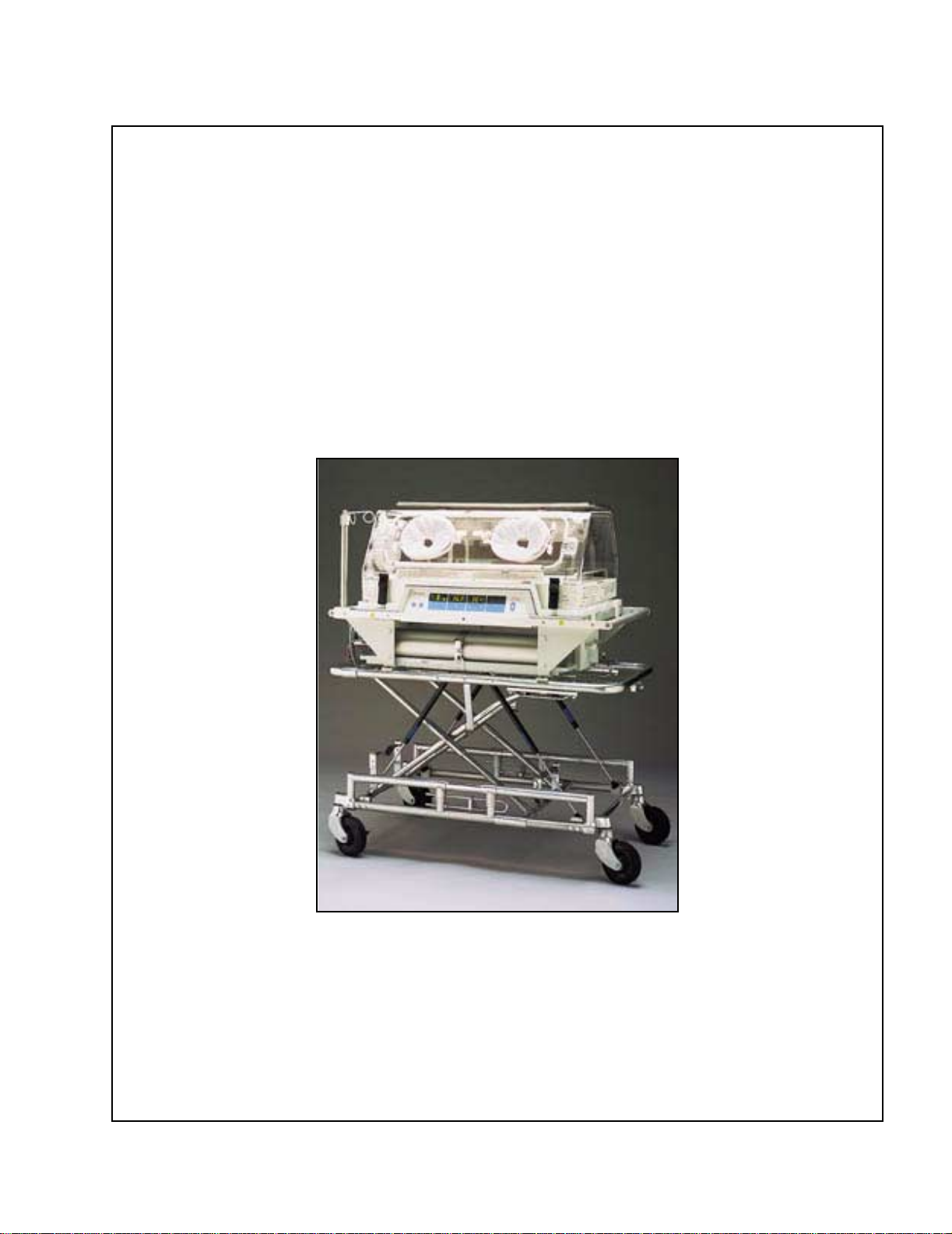
Transport
Incubator
From Hill-Rom Air-Shields
Product No. TI500/TI500-1/TI500-1E/TI500-1C
For Parts or Technical Assistance man188rc
USA (800) 445-3720 Canada (800) 267-2337 67 990 11-11
International: Contact your distributor.


Revisions
Transport Incubator
Service Manual
Revision Letter Pages Affected Date
Original Issue February, 1999
A v, 1-4, 3-3, 3-5, 4-3, 4-4,
6-1A, 6-3, 6-9, 6-39
B Front cover, Warranty, A,
B, 5-2
C All January, 2002
October, 1999
December, 1999
man188rc (67 990 11-11)
Transport Incubator Service Manual (man188rc) Page i

Revisions
© 2002 by Hill-Rom Services, Inc. ALL RIGHTS RESERVED.
No part of this text shall be reproduced or transmitted in any form or by any
means, electronic or mechanical, including photocopying, recording, or by any
information or retrieval system without written permission from
Hill-Rom Services, Inc. (Hill-Rom).
The information in this manual is confidential and may not be disclosed to
third parties without the prior written consent of Hill-Rom.
Fourth Edition
First Printing 1999
Printed in the USA
Air-Shields® is a registered trademark of Hill-Rom Services, Inc.
Bio-Tek® is a registered trademark of Bio-Tek Instruments, Inc.
Critter Covers® is a registered trademark of Hill-Rom Services, Inc.
FERNO® is a registered trademark of Ferno-Washington, Inc.
Fluke® is a registered trademark of Fluke Corporation.
Globe-Trotter™ is a trademark of Hill-Rom Services, Inc.
Hill-Rom Air-Shields™ is a trademark of Hill-Rom Services, Inc.
Hill-Rom® is a registered trademark of Hill-Rom Services, Inc.
Kleenaseptic® is a registered trademark of Predicted Environments, Inc.
Loctite® is a registered trademark of Loctite Corporation.
Molykote® is a registered trademark of Alpha Molykote Corporation.
Nylok® is a registered trademark of Nylok Fastener Corporation.
Oilite® is a registered trademark of Beemer Precision, Incorporated.
Plastite® is a registered trademark of Research Engineering & Manufacturing,
Inc.
Plexiglas® is a registered trademark of Rohm and Haas Company.
Page ii Transport Incubator Service Manual (man188rc)

Revisions
Teflon® is a registered trademark of E. I. du Pont and de Nemours and
Company.
Tektronix™ is a trademark of Tektronix, Inc.
Transzorb® is a registered trademark of General Semiconductor, Inc.
Variac® is a registered trademark of General Radio Company.
Velcro® is a registered trademark of Velcro Industries, BV (a Dutch
corporation).
The information contained in this manual is subject to change without notice.
Hill-Rom makes no commitment to update or keep current, the information
contained in this manual.
The only product warranty intended by Hill-Rom is the express, written
warranty accompanying the bill of sale to the original purchaser. Hill-Rom
makes no other warranty, express or implied, and in particular, makes no
warranty of merchantability or fitness for a particular purpose.
Additional copies of this manual can be obtained from Hill-Rom.
To order additional copies of this manual, call (800) 445-3720, and place a
parts order for part number man188rc (67 990 11-11).
Transport Incubator Service Manual (man188rc) Page iii

Revisions
NOTES:
Page iv Transport Incubator Service Manual (man188rc)

Table of Contents
Chapter 1: Introduction
Purpose . . . . . . . . . . . . . . . . . . . . . . . . . . . . . . . . . . . . . . . . . . . . . . . . . . . . . . . . . . 1 - 3
Audience. . . . . . . . . . . . . . . . . . . . . . . . . . . . . . . . . . . . . . . . . . . . . . . . . . . . . . . . . 1 - 3
Organization . . . . . . . . . . . . . . . . . . . . . . . . . . . . . . . . . . . . . . . . . . . . . . . . . . . . . . 1 - 3
Chapter 1: Introduction. . . . . . . . . . . . . . . . . . . . . . . . . . . . . . . . . . . . . . . . . . . 1 - 3
Chapter 2: Troubleshooting Procedures . . . . . . . . . . . . . . . . . . . . . . . . . . . . . . 1 - 3
Chapter 3: Theory of Operation . . . . . . . . . . . . . . . . . . . . . . . . . . . . . . . . . . . . 1 - 3
Chapter 4: Removal, Replacement, and Adjustment Procedures. . . . . . . . . . . 1 - 3
Chapter 5: Parts List . . . . . . . . . . . . . . . . . . . . . . . . . . . . . . . . . . . . . . . . . . . . . 1 - 4
Chapter 6: General Procedures . . . . . . . . . . . . . . . . . . . . . . . . . . . . . . . . . . . . . 1 - 4
Chapter 7: Accessories . . . . . . . . . . . . . . . . . . . . . . . . . . . . . . . . . . . . . . . . . . . 1 - 4
Typographical Conventions . . . . . . . . . . . . . . . . . . . . . . . . . . . . . . . . . . . . . . . . . . 1 - 5
Technical Definitions . . . . . . . . . . . . . . . . . . . . . . . . . . . . . . . . . . . . . . . . . . . . . . . 1 - 7
Introduction. . . . . . . . . . . . . . . . . . . . . . . . . . . . . . . . . . . . . . . . . . . . . . . . . . . . . . . 1 - 8
Overview. . . . . . . . . . . . . . . . . . . . . . . . . . . . . . . . . . . . . . . . . . . . . . . . . . . . . . 1 - 8
Operating Precautions. . . . . . . . . . . . . . . . . . . . . . . . . . . . . . . . . . . . . . . . . . . . 1 - 8
Features. . . . . . . . . . . . . . . . . . . . . . . . . . . . . . . . . . . . . . . . . . . . . . . . . . . . . . . 1 - 8
Temperature Control. . . . . . . . . . . . . . . . . . . . . . . . . . . . . . . . . . . . . . . . . . 1 - 8
Alarms. . . . . . . . . . . . . . . . . . . . . . . . . . . . . . . . . . . . . . . . . . . . . . . . . . . . . 1 - 9
Adjustable Stand Assembly (Accessory) . . . . . . . . . . . . . . . . . . . . . . . . . 1 - 10
Specifications . . . . . . . . . . . . . . . . . . . . . . . . . . . . . . . . . . . . . . . . . . . . . . . . . . . . 1 - 11
Physical Description . . . . . . . . . . . . . . . . . . . . . . . . . . . . . . . . . . . . . . . . . . . . 1 - 11
Environmental Description. . . . . . . . . . . . . . . . . . . . . . . . . . . . . . . . . . . . . . . 1 - 12
Electrical Description . . . . . . . . . . . . . . . . . . . . . . . . . . . . . . . . . . . . . . . . . . . 1 - 13
Regulations, Standards, and Codes. . . . . . . . . . . . . . . . . . . . . . . . . . . . . . . . . 1 - 13
Model Identification and Series Changes. . . . . . . . . . . . . . . . . . . . . . . . . . . . . . . 1 - 14
Safety Tips . . . . . . . . . . . . . . . . . . . . . . . . . . . . . . . . . . . . . . . . . . . . . . . . . . . . . . 1 - 15
Transport Incubator Service Manual (man188rc) Page v

Table of Contents
Warning and Caution Labels . . . . . . . . . . . . . . . . . . . . . . . . . . . . . . . . . . . . . . . . 1 - 20
Chapter 2: Troubleshooting Procedures
Getting Started . . . . . . . . . . . . . . . . . . . . . . . . . . . . . . . . . . . . . . . . . . . . . . . . . . . . 2 - 3
Initial Actions . . . . . . . . . . . . . . . . . . . . . . . . . . . . . . . . . . . . . . . . . . . . . . . . . . . . . 2 - 3
Function Checks and General Operation Checkout . . . . . . . . . . . . . . . . . . . . . . . . 2 - 4
Mechanical Checkout . . . . . . . . . . . . . . . . . . . . . . . . . . . . . . . . . . . . . . . . . . . . 2 - 9
Final Actions. . . . . . . . . . . . . . . . . . . . . . . . . . . . . . . . . . . . . . . . . . . . . . . . . . . . . 2 - 13
Power Distribution Does Not Operate Properly . . . . . . . . . . . . . . . . . . . . . . . . . . 2 - 14
The Auto-Test Function Does Not Operate Properly. . . . . . . . . . . . . . . . . . . . . . 2 - 20
The Air Temperature Display Does Not Function Properly. . . . . . . . . . . . . . . . . 2 - 21
The Sensor Alarm Does Not Activate . . . . . . . . . . . . . . . . . . . . . . . . . . . . . . . . . 2 - 22
The Baby Temperature Alarm Does Not Function Properly . . . . . . . . . . . . . . . . 2 - 23
The Power Failure Alarm Does Not Function Properly . . . . . . . . . . . . . . . . . . . . 2 - 24
The Set Temp Indicator Does Not Function Properly . . . . . . . . . . . . . . . . . . . . . 2 - 25
The High Temperature Alarm Does Not Function Properly . . . . . . . . . . . . . . . . 2 - 26
Chapter 3: Theory of Operation
Electrical System . . . . . . . . . . . . . . . . . . . . . . . . . . . . . . . . . . . . . . . . . . . . . . . . . . 3 - 3
Theory of Operation . . . . . . . . . . . . . . . . . . . . . . . . . . . . . . . . . . . . . . . . . . . . . . . . 3 - 6
Detailed Circuit Description. . . . . . . . . . . . . . . . . . . . . . . . . . . . . . . . . . . . . . . 3 - 6
Input Power Circuit Sources. . . . . . . . . . . . . . . . . . . . . . . . . . . . . . . . . . . . 3 - 6
Power Source Priority. . . . . . . . . . . . . . . . . . . . . . . . . . . . . . . . . . . . . . . . . 3 - 8
Battery Charger. . . . . . . . . . . . . . . . . . . . . . . . . . . . . . . . . . . . . . . . . . . . . . 3 - 9
Heater Drivers. . . . . . . . . . . . . . . . . . . . . . . . . . . . . . . . . . . . . . . . . . . . . . 3 - 10
Switching Power Supplies . . . . . . . . . . . . . . . . . . . . . . . . . . . . . . . . . . . . 3 - 10
Fault Protection. . . . . . . . . . . . . . . . . . . . . . . . . . . . . . . . . . . . . . . . . . . . . 3 - 11
Exam Lights . . . . . . . . . . . . . . . . . . . . . . . . . . . . . . . . . . . . . . . . . . . . . . . 3 - 11
Feed-Through Connections. . . . . . . . . . . . . . . . . . . . . . . . . . . . . . . . . . . . 3 - 11
Controller P.C. Board . . . . . . . . . . . . . . . . . . . . . . . . . . . . . . . . . . . . . . . . 3 - 12
Power On/Off Circuitry . . . . . . . . . . . . . . . . . . . . . . . . . . . . . . . . . . . . . . 3 - 12
Skin Temperature . . . . . . . . . . . . . . . . . . . . . . . . . . . . . . . . . . . . . . . . . . . 3 - 13
Air-Temperature-Monitoring Circuitry . . . . . . . . . . . . . . . . . . . . . . . . . . 3 - 14
Page vi Transport Incubator Service Manual (man188rc)

Table of Contents
Setpoint Circuitry . . . . . . . . . . . . . . . . . . . . . . . . . . . . . . . . . . . . . . . . . . . 3 - 16
Air-Temperature-Controlling Circuitry . . . . . . . . . . . . . . . . . . . . . . . . . . 3 - 19
Clock and Timing Circuitry . . . . . . . . . . . . . . . . . . . . . . . . . . . . . . . . . . . 3 - 20
Alarms. . . . . . . . . . . . . . . . . . . . . . . . . . . . . . . . . . . . . . . . . . . . . . . . . . . . 3 - 22
Alarm Indicators . . . . . . . . . . . . . . . . . . . . . . . . . . . . . . . . . . . . . . . . . . . . 3 - 26
Auto-Test Function. . . . . . . . . . . . . . . . . . . . . . . . . . . . . . . . . . . . . . . . . . 3 - 27
Chapter 4: Removal, Replacement, and Adjustment Procedures
Control Panel Assembly . . . . . . . . . . . . . . . . . . . . . . . . . . . . . . . . . . . . . . . . . . . . . 4 - 3
Removal . . . . . . . . . . . . . . . . . . . . . . . . . . . . . . . . . . . . . . . . . . . . . . . . . . . . . . 4 - 3
Replacement . . . . . . . . . . . . . . . . . . . . . . . . . . . . . . . . . . . . . . . . . . . . . . . . . . . 4 - 3
Power Chassis. . . . . . . . . . . . . . . . . . . . . . . . . . . . . . . . . . . . . . . . . . . . . . . . . . . . . 4 - 4
Removal . . . . . . . . . . . . . . . . . . . . . . . . . . . . . . . . . . . . . . . . . . . . . . . . . . . . . . 4 - 4
Replacement . . . . . . . . . . . . . . . . . . . . . . . . . . . . . . . . . . . . . . . . . . . . . . . . . . . 4 - 5
Battery Tray . . . . . . . . . . . . . . . . . . . . . . . . . . . . . . . . . . . . . . . . . . . . . . . . . . . . . . 4 - 6
Removal . . . . . . . . . . . . . . . . . . . . . . . . . . . . . . . . . . . . . . . . . . . . . . . . . . . . . . 4 - 6
Replacement . . . . . . . . . . . . . . . . . . . . . . . . . . . . . . . . . . . . . . . . . . . . . . . . . . . 4 - 8
Battery. . . . . . . . . . . . . . . . . . . . . . . . . . . . . . . . . . . . . . . . . . . . . . . . . . . . . . . . . . . 4 - 9
Removal . . . . . . . . . . . . . . . . . . . . . . . . . . . . . . . . . . . . . . . . . . . . . . . . . . . . . . 4 - 9
Replacement . . . . . . . . . . . . . . . . . . . . . . . . . . . . . . . . . . . . . . . . . . . . . . . . . . 4 - 10
Heater Assembly. . . . . . . . . . . . . . . . . . . . . . . . . . . . . . . . . . . . . . . . . . . . . . . . . . 4 - 11
Removal . . . . . . . . . . . . . . . . . . . . . . . . . . . . . . . . . . . . . . . . . . . . . . . . . . . . . 4 - 11
Replacement . . . . . . . . . . . . . . . . . . . . . . . . . . . . . . . . . . . . . . . . . . . . . . . . . . 4 - 11
Thermostat . . . . . . . . . . . . . . . . . . . . . . . . . . . . . . . . . . . . . . . . . . . . . . . . . . . . . . 4 - 14
Removal . . . . . . . . . . . . . . . . . . . . . . . . . . . . . . . . . . . . . . . . . . . . . . . . . . . . . 4 - 14
Replacement . . . . . . . . . . . . . . . . . . . . . . . . . . . . . . . . . . . . . . . . . . . . . . . . . . 4 - 14
Fan Motor . . . . . . . . . . . . . . . . . . . . . . . . . . . . . . . . . . . . . . . . . . . . . . . . . . . . . . . 4 - 15
Removal . . . . . . . . . . . . . . . . . . . . . . . . . . . . . . . . . . . . . . . . . . . . . . . . . . . . . 4 - 15
Replacement . . . . . . . . . . . . . . . . . . . . . . . . . . . . . . . . . . . . . . . . . . . . . . . . . . 4 - 17
Controller P.C. Board . . . . . . . . . . . . . . . . . . . . . . . . . . . . . . . . . . . . . . . . . . . . . . 4 - 19
Removal . . . . . . . . . . . . . . . . . . . . . . . . . . . . . . . . . . . . . . . . . . . . . . . . . . . . . 4 - 19
Replacement . . . . . . . . . . . . . . . . . . . . . . . . . . . . . . . . . . . . . . . . . . . . . . . . . . 4 - 19
Transport Incubator Service Manual (man188rc) Page vii

Table of Contents
Power P.C. Board . . . . . . . . . . . . . . . . . . . . . . . . . . . . . . . . . . . . . . . . . . . . . . . . . 4 - 21
Removal . . . . . . . . . . . . . . . . . . . . . . . . . . . . . . . . . . . . . . . . . . . . . . . . . . . . . 4 - 21
Replacement . . . . . . . . . . . . . . . . . . . . . . . . . . . . . . . . . . . . . . . . . . . . . . . . . . 4 - 21
Chapter 5: Parts List
Warranty . . . . . . . . . . . . . . . . . . . . . . . . . . . . . . . . . . . . . . . . . . . . . . . . . . . . . . . . . 5 - 3
Service Parts Ordering . . . . . . . . . . . . . . . . . . . . . . . . . . . . . . . . . . . . . . . . . . . . . . 5 - 5
Exchange Policy . . . . . . . . . . . . . . . . . . . . . . . . . . . . . . . . . . . . . . . . . . . . . . . . . . . 5 - 7
In-Warranty Exchanges . . . . . . . . . . . . . . . . . . . . . . . . . . . . . . . . . . . . . . . . . . 5 - 7
Out-of-Warranty Exchanges. . . . . . . . . . . . . . . . . . . . . . . . . . . . . . . . . . . . . . . 5 - 7
Recommended Spare Parts . . . . . . . . . . . . . . . . . . . . . . . . . . . . . . . . . . . . . . . . . . . 5 - 8
Transport Incubator. . . . . . . . . . . . . . . . . . . . . . . . . . . . . . . . . . . . . . . . . . . . . . . . 5 - 10
Base Assembly with Handrail—P/N 67 502 70 . . . . . . . . . . . . . . . . . . . . . . . . . . 5 - 14
Replacement Outer Hood Assembly—P/N 67 506 70-R and 67 908 60 . . . . . . . 5 - 20
Control Panel Assembly—P/N 67 503 70-R . . . . . . . . . . . . . . . . . . . . . . . . . . . . 5 - 24
Power Chassis Assembly—P/N 67 407 70-R and 67 407 80-R. . . . . . . . . . . . . . 5 - 26
Battery Tray Assembly—P/N 67 504 70 . . . . . . . . . . . . . . . . . . . . . . . . . . . . . . . 5 - 30
Battery Tray Cable Assembly—P/N 67 504 30 . . . . . . . . . . . . . . . . . . . . . . . . . . 5 - 32
Heater Assembly—P/N 67 502 55-R . . . . . . . . . . . . . . . . . . . . . . . . . . . . . . . . . . 5 - 33
Incandescent Lamp Assembly—P/N 67 505 70. . . . . . . . . . . . . . . . . . . . . . . . . . 5 - 34
Model HLS-101 Adjustable Stand—P/N 67 090 72 (Accessory) . . . . . . . . . . . . 5 - 36
IV Pole Assembly—P/N 67 091 80 (Accessory) . . . . . . . . . . . . . . . . . . . . . . . . . 5 - 40
Accessory Shelf Kit—P/N 67 503 30 and 67 515 00/01/02/03/04/05 and Mount
(Accessory). . . . . . . . . . . . . . . . . . . . . . . . . . . . . . . . . . . . . . . . . . . . . . . . . . . . . . 5 - 42
Controller P.C. Board Assembly (PCB1)—P/N 67 509 71 . . . . . . . . . . . . . . . . . 5 - 46
Power P.C. Board Assembly (PCB2)—P/N 67 508 70 . . . . . . . . . . . . . . . . . . . . 5 - 54
Chapter 6: General Procedures
Cleaning . . . . . . . . . . . . . . . . . . . . . . . . . . . . . . . . . . . . . . . . . . . . . . . . . . . . . . . . . 6 - 3
Steam Cleaning. . . . . . . . . . . . . . . . . . . . . . . . . . . . . . . . . . . . . . . . . . . . . . . . . 6 - 4
Cleaning Hard to Clean Spots. . . . . . . . . . . . . . . . . . . . . . . . . . . . . . . . . . . . . . 6 - 4
Disinfecting. . . . . . . . . . . . . . . . . . . . . . . . . . . . . . . . . . . . . . . . . . . . . . . . . . . . 6 - 4
Disassembly, Cleaning, and Assembly. . . . . . . . . . . . . . . . . . . . . . . . . . . . . . . . . . 6 - 5
Page viii Transport Incubator Service Manual (man188rc)

Table of Contents
Disassembly . . . . . . . . . . . . . . . . . . . . . . . . . . . . . . . . . . . . . . . . . . . . . . . . . . . 6 - 5
Cleaning . . . . . . . . . . . . . . . . . . . . . . . . . . . . . . . . . . . . . . . . . . . . . . . . . . . . . . 6 - 8
Assembly . . . . . . . . . . . . . . . . . . . . . . . . . . . . . . . . . . . . . . . . . . . . . . . . . . . . 6 - 10
Component Handling . . . . . . . . . . . . . . . . . . . . . . . . . . . . . . . . . . . . . . . . . . . . . . 6 - 12
P.C. Board. . . . . . . . . . . . . . . . . . . . . . . . . . . . . . . . . . . . . . . . . . . . . . . . . . . . 6 - 12
Lubrication Requirements. . . . . . . . . . . . . . . . . . . . . . . . . . . . . . . . . . . . . . . . . . . 6 - 13
Preventive Maintenance . . . . . . . . . . . . . . . . . . . . . . . . . . . . . . . . . . . . . . . . . . . . 6 - 14
Preventive Maintenance Schedule . . . . . . . . . . . . . . . . . . . . . . . . . . . . . . . . . 6 - 15
Preventive Maintenance Checklist . . . . . . . . . . . . . . . . . . . . . . . . . . . . . . . . . 6 - 16
Installation . . . . . . . . . . . . . . . . . . . . . . . . . . . . . . . . . . . . . . . . . . . . . . . . . . . . . . 6 - 17
Unpacking. . . . . . . . . . . . . . . . . . . . . . . . . . . . . . . . . . . . . . . . . . . . . . . . . . . . 6 - 17
Assembly . . . . . . . . . . . . . . . . . . . . . . . . . . . . . . . . . . . . . . . . . . . . . . . . . . . . 6 - 17
Battery Maintenance. . . . . . . . . . . . . . . . . . . . . . . . . . . . . . . . . . . . . . . . . . . . . . . 6 - 23
Calibration . . . . . . . . . . . . . . . . . . . . . . . . . . . . . . . . . . . . . . . . . . . . . . . . . . . . . . 6 - 24
Tool and Supply Requirements. . . . . . . . . . . . . . . . . . . . . . . . . . . . . . . . . . . . . . . 6 - 30
Chapter 7: Accessories
Accessories . . . . . . . . . . . . . . . . . . . . . . . . . . . . . . . . . . . . . . . . . . . . . . . . . . . . . . . 7 - 3
Transport Incubator Service Manual (man188rc) Page ix

Table of Contents
NOTES:
Page x Transport Incubator Service Manual (man188rc)

Chapter 1
Introduction
Chapter Contents
Purpose . . . . . . . . . . . . . . . . . . . . . . . . . . . . . . . . . . . . . . . . . . . . . . . . . . . . . . . . . . 1 - 3
Audience. . . . . . . . . . . . . . . . . . . . . . . . . . . . . . . . . . . . . . . . . . . . . . . . . . . . . . . . . 1 - 3
Organization . . . . . . . . . . . . . . . . . . . . . . . . . . . . . . . . . . . . . . . . . . . . . . . . . . . . . . 1 - 3
Chapter 1: Introduction. . . . . . . . . . . . . . . . . . . . . . . . . . . . . . . . . . . . . . . . . . . 1 - 3
Chapter 2: Troubleshooting Procedures . . . . . . . . . . . . . . . . . . . . . . . . . . . . . . 1 - 3
Chapter 3: Theory of Operation . . . . . . . . . . . . . . . . . . . . . . . . . . . . . . . . . . . . 1 - 3
Chapter 4: Removal, Replacement, and Adjustment Procedures. . . . . . . . . . . 1 - 3
1
Chapter 5: Parts List . . . . . . . . . . . . . . . . . . . . . . . . . . . . . . . . . . . . . . . . . . . . . 1 - 4
Chapter 6: General Procedures . . . . . . . . . . . . . . . . . . . . . . . . . . . . . . . . . . . . . 1 - 4
Chapter 7: Accessories . . . . . . . . . . . . . . . . . . . . . . . . . . . . . . . . . . . . . . . . . . . 1 - 4
Typographical Conventions . . . . . . . . . . . . . . . . . . . . . . . . . . . . . . . . . . . . . . . . . . 1 - 5
Technical Definitions . . . . . . . . . . . . . . . . . . . . . . . . . . . . . . . . . . . . . . . . . . . . . . . 1 - 7
Introduction. . . . . . . . . . . . . . . . . . . . . . . . . . . . . . . . . . . . . . . . . . . . . . . . . . . . . . . 1 - 8
Overview. . . . . . . . . . . . . . . . . . . . . . . . . . . . . . . . . . . . . . . . . . . . . . . . . . . . . . 1 - 8
Operating Precautions. . . . . . . . . . . . . . . . . . . . . . . . . . . . . . . . . . . . . . . . . . . . 1 - 8
Features. . . . . . . . . . . . . . . . . . . . . . . . . . . . . . . . . . . . . . . . . . . . . . . . . . . . . . . 1 - 8
Temperature Control. . . . . . . . . . . . . . . . . . . . . . . . . . . . . . . . . . . . . . . . . . 1 - 8
Alarms. . . . . . . . . . . . . . . . . . . . . . . . . . . . . . . . . . . . . . . . . . . . . . . . . . . . . 1 - 9
Adjustable Stand Assembly (Accessory) . . . . . . . . . . . . . . . . . . . . . . . . . 1 - 10
Specifications . . . . . . . . . . . . . . . . . . . . . . . . . . . . . . . . . . . . . . . . . . . . . . . . . . . . 1 - 11
Physical Description . . . . . . . . . . . . . . . . . . . . . . . . . . . . . . . . . . . . . . . . . . . . 1 - 11
Environmental Description. . . . . . . . . . . . . . . . . . . . . . . . . . . . . . . . . . . . . . . 1 - 12
Electrical Description . . . . . . . . . . . . . . . . . . . . . . . . . . . . . . . . . . . . . . . . . . . 1 - 13
Transport Incubator Service Manual (man188rc) Page 1 - 1

Chapter 1: Introduction
Regulations, Standards, and Codes. . . . . . . . . . . . . . . . . . . . . . . . . . . . . . . . . 1 - 13
Model Identification and Series Changes. . . . . . . . . . . . . . . . . . . . . . . . . . . . . . . 1 - 14
Safety Tips . . . . . . . . . . . . . . . . . . . . . . . . . . . . . . . . . . . . . . . . . . . . . . . . . . . . . . 1 - 15
Warning and Caution Labels . . . . . . . . . . . . . . . . . . . . . . . . . . . . . . . . . . . . . . . . 1 - 20
Page 1 - 2 Transport Incubator Service Manual (man188rc)

Purpose
This manual provides requirements for the Transport Incubator normal
operation and maintenance. It also includes parts lists (in chapter 5) for
ordering replacement components.
Audience
This manual is intended for use by only facility-authorized personnel. Failure
to observe this restriction can result in severe injury to people and serious
damage to equipment.
Organization
This manual contains seven chapters.
Purpose
Chapter 1: Introduction
1
Chapter 1: Introduction
In addition to a brief description of this service manual, chapter 1 also provides
a product overview.
Chapter 2: Troubleshooting Procedures
Repair analysis procedures are contained in this chapter. Use these procedures
to gather information, identify the maintenance need, and verify the
effectiveness of the repair.
Chapter 3: Theory of Operation
This chapter describes the application of the mechanical, electrical, and
hydraulic systems employed in this product.
Chapter 4: Removal, Replacement, and Adjustment Procedures
Chapter 4 contains the detailed maintenance procedures determined necessary
in chapter 2.
Transport Incubator Service Manual (man188rc) Page 1 - 3

Organization
Chapter 1: Introduction
Chapter 5: Parts List
This chapter contains the warranty, part-ordering procedure, and illustrated
parts lists.
Chapter 6: General Procedures
Cleaning, preventive maintenance, and other general procedures are described
in this chapter.
Chapter 7: Accessories
A list of additional products, that can be used in conjunction with the Transport
Incubator, is available in chapter 7. Installation procedures for these
accessories are also included.
Page 1 - 4 Transport Incubator Service Manual (man188rc)
Typographical Conventions
This manual contains different typefaces and icons designed to improve
readability and increase understanding of its content. Note the following
examples:
• Standard text—used for regular information.
• Boldface text—emphasizes a word or phrase.
• NOTE:—sets apart special information or important instruction
clarification.
• The symbol below highlights a WARNING or CAUTION:
Figure 1-1. Warning and Caution
– A WARNING identifies situations or actions that may affect
patient or user safety. Disregarding a warning could result in
patient or user injury.
Typographical Conventions
Chapter 1: Introduction
1
– A CAUTION points out special procedures or precautions that
personnel must follow to avoid equipment damage.
• The symbol below highlights a CAUGHT HAZARD WARNING:
Figure 1-2. Caught Hazard Warning
• The symbol below highlights a CHEMICAL HAZARD WARNING:
Figure 1-3. Chemical Hazard Warning
• The symbol below highlights an ELECTRICAL SHOCK HAZARD
WARNING:
Figure 1-4. Electrical Shock Hazard Warning
Transport Incubator Service Manual (man188rc) Page 1 - 5
Typographical Conventions
Chapter 1: Introduction
The Transport Incubator contains different icons designed to increase
understanding. Note the following examples:
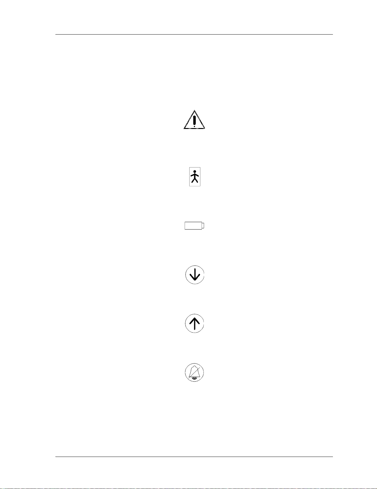
• The symbol below indicates “Attention, consult accompanying
documents:”
Figure 1-5. Attention, Consult Accompanying Documents
• The symbol below indicates “Type B equipment with an F-type isolated
(floating) applied part:”
Figure 1-6. Type B Equipment with an F-Type Isolated (Floating) Applied Part
• The symbol below indicates the Battery indicator:
Figure 1-7. Battery Indicator
• The symbol below indicates the Set Temperature Down arrow key:
Figure 1-8. Set Temperature Down Arrow Key
• The symbol below indicates the Set Temperature Up arrow key:
Figure 1-9. Set Temperature Up Arrow Key
• The symbol below indicates the Silence/Reset key:
Figure 1-10. Silence/Reset Key
Page 1 - 6 Transport Incubator Service Manual (man188rc)

Technical Definitions
This manual contains different technical terms. For the technical definitions of
these terms, see table 1-1 on page 1-7.
Term Definition
Setpoint The temperature of the incubator selected for
Incubator temperature The air temperature at a point 10 cm (4") above
Temperature
equilibrium
Temperature overshoot The amount by which the incubator’s temperature
Temperature rise time The time required for the incubator’s temperature
Temperature uniformity The amount by which the average temperature at
Technical Definitions
Chapter 1: Introduction
1
Table 1-1. Technical Definitions
operation during use.
and centered over the mattress surface.
The condition reached when the average incubator
temperature does not vary more than 0.2°C over a
period of one hour.
exceeds the average incubator temperature at
temperature equilibrium when the setpoint changes
from 30°C (86°F) to 34°C (93°F).
to rise to 34°C (93°F) from an ambient of 23°C
(73°F) with a 36°C (97°F) setpoint.
each of the four points 10 cm (4") above the
mattress surface differs from the average incubator
temperature at temperature equilibrium. The four
points are the centers of the four areas formed by
lines dividing the width and length of the mattress
surface evenly.
Temperature variability The variability of the incubator’s temperature
observed over a 1 hour period after temperature
equilibrium is reached.
Transport Incubator Service Manual (man188rc) Page 1 - 7

Introduction
Chapter 1: Introduction
Introduction
Overview
The Transport Incubator is for transport of high risk, premature, low birthweight or critically ill newborns. It provides a means to control air temperature
and oxygen concentrations, and adds relative humidity. A double-walled hood
provides full visibility and an effective thermal and sound barrier from the
environment. Arm ports and door panels provide front and head access, and the
mattress tray slides out of the head end for additional access. Tubing access
grommets are on both sides of the front access panel and at the left-hand, head
end panel. An observation lamp is also included.
The Transport Incubator operates from either a sine- or sq uare-wave AC power
source. In addition, it can operate from an external 12V DC or 28V DC source
or integral 12V batteries. The batteries automatically charge whenever the unit
is connected to an AC voltage source and the main Power switch is set to the
ON-1 position. A comprehensive visual and audible alarm system is included
with a test function to verify proper alarm operation. A Battery indicator is
also provided.
Operating Precautions
For additional operating precautions for the Transport Incubator and its
accessories, refer to the Transport Incubator (Model TI500) User Manual
(usr038).
Features
Temperature Control
A temperature sensor, located in the recirculation air path, and a proportional
control circuit, which determines the heater output to maintain the desired
incubator temperature, regulate the incubator temperature. The relative amount
of heat provided is indicated by the number of Heater indicators lit on the
control panel. The incubator temperature can be maintained at 38.0°C
(100.4°F) as selected by the temperature controls on the control panel. The
temperature, as sensed by a sensor located within the housing, is compared
with the setpoint. Control circuitry uses the information from this sensor to
proportion the heater output to maintain the setpoint. The temperature appears
on the front panel’s Temperature display.
Page 1 - 8 Transport Incubator Service Manual (man188rc)

Introduction
Chapter 1: Introduction
The initial setpoint is 36.0°C (96.8°F) ± 0.1°C. The incubator heats to this
temperature unless the setting is changed. To change the setpoint to a
prescribed temperature, use the Set Temp controls on the control panel. An
additional sensor within the housing serves as a backup to limit the incubator’s
maximum air temperature to 38.9°C (102.0°F) ± 0.5°C. At this limit, the High
Temp alarm activates, and the heater shuts off.
Alarms
Each time the unit turns on, it automatically activates a test sequence to verify
that the visual display and the audible alarm function. Each of the following six
alarms has an indicator on the display and an audible alarm.
High Temperature Alarm
When the incubator temperature is ≥38.9°C (102.0°F), a sensor located below
the deck sounds this alarm. A flashing High Temp indicator and an audible
tone indicate a High Temp alarm. Internally, the heater turns off. To silence
this alarm for 5 minutes, press the Silence/Reset key.
1
Sensor Alarm
Circuitry monitors the air temperature sensor and the air display sensor for
short- or open-circuits or skin temperature probe shorts. A flashing Sensor
indicator and an intermittent audible tone indicate a Sensor alarm. This alarm
resets itself.
High Heater Temperature Alarm
A flashing Heater Temp indicator and an intermittent audible tone indicate
that the heater temperature exceeds 77.0°C (170.6°F). When this occurs, the
heater and Heater indicators turn off. To silence this alarm for 5 minutes, press
the Silence/Reset key.
Airflow Alarm
A flashing Air Flow indicator and an intermittent audible alarm indicate that
the fan impeller is not rotating or is missing. When this occurs, the heater and
Heater indicators turn off. To silence this alarm for 5 minutes, press the
Silence/Reset key.
Low DC Alarm
A flashing Low DC indicator and an intermittent audible alarm indicate that
the incubator’s DC power source is below the minimum specification value.
Transport Incubator Service Manual (man188rc) Page 1 - 9

Introduction
Chapter 1: Introduction
Power Failure Alarm
A separate internal battery powers the Power Failure alarm. If AC power is
lost and no external DC power source or internal battery is present, the Power
Fail indicator lights, and a continuous tone sounds. If the power source
switches from an AC power source or a DC power source to an internal
battery, the Power Fail indicator lights, and an intermittent tone sounds. To
reset this alarm, press the Silence/Reset key.
Adjustable Stand Assembly (Accessory)
The adjustable stand assembly provides a convenient means of moving the
Transport Incubator. Each adjustable stand assembly adjusts to different height
positions and locks into the litter bar of an ambulance, such as a FERNO®1
Model 175 Series Cot Fastener System.
1. FERNO® is a registered trademark of Ferno-Washington, Inc.
Page 1 - 10 Transport Incubator Service Manual (man188rc)

Specifications
Physical Description
For Transport Incubator physical specifications, see table 1-2 on page 1-11.
Specifications
Chapter 1: Introduction
1
Table 1-2. Physical Specifications
Feature Dimension
Length (with accessory adjustable stand
assembly)
Width (with accessory adjustable stand
assembly)
Height (Model TI500 with accessory
adjustable stand assembly)
Height (Model TI500-1/1E/1C with
accessory adjustable stand assembly)
Weight (including accessory adjustable
stand assembly and one battery)
Battery tray weight with one battery 10.4 kg (22.9 lb)
Battery tray weight with two batteries 19.4 kg (42.8 lb)
T emperature setpoint range 21.5°C (70.7°F) ± 1.5°C (2.7°F)
Temperature rise time 30 minutes
Temperature variability ≤ 1.0°C (1.8°F)
Temperature overshoot ≤ 2.0°C (3.6°F)
102 cm (40")
56.5 cm (22.2")
81.3 cm (32.0") to 111.8 cm
(44.0")
85.73 cm (33¾") to 116.2 cm
(45¾")
72 kg (159 lb)
to 38.0°C (100.4°F) in 0.1°C
(0.2°F) increments
Temperature uniformity ≤ 1.0°C (1.8°F)
Correlation of the displayed incubator
temperature to the actual incubator
temperature at temperature equilibrium
Correlation of the displayed incubator
temperature to the setpoint at temperature
equilibrium (20°C to 30°C ambients)
Correlation of the displayed incubator
temperature to the setpoint at temperature
equilibrium (10°C to 20°C ambients)
Transport Incubator Service Manual (man188rc) Page 1 - 11
≤ 1.0°C (1.8°F)
≤ 1.5°C (2.7°F)
≤ 2.0°C (3.6°F)

Specifications
Chapter 1: Introduction
Observation light 376.7 lx (35.0 fc) at 10 cm (4")
Oxygen concentration range From 21% to at least 58%
Feature Dimension
above the center of the mattress
Carbon dioxide (CO2) level within the
hood
Noise level within the hood environment < 60 dBa with ambient noise of
Environmental Description
For Transport Incubator environmental specifications, see table 1-3 on page 1-
12.
Table 1-3. Environmental Specifications
Feature Dimension
Operating temperature Maintained at a differential of
Normal operating temperature range 10°C (50°F) to 30°C (86°F)
< 0.5% when a 4% mixture of
CO2 in the air is delivered at
750 ml/min at 10 cm (4") above
the center of the mattress
≤ 50 dBa
25°C between the ambient
temperature and the setpoint for
90 minutes per battery
Limited operating temperature range 0°C (32°F) to 40°C (104°F)
Relative humidity (RH) operating range 0% to 95%, non-condensing
Altitude operating range (non-pressurized
Sea level to 3 km (9843 ft)
ambient atmosphere)
Altitude operating range (pressurized
Sea level to 12 km (39370 ft)
ambient atmosphere)
Altitude shipment range Sea level to 12 km (39370 ft)
Page 1 - 12 Transport Incubator Service Manual (man188rc)

Electrical Description
For Transport Incubator electrical specifications, see table 1-4 on page 1-13.
Table 1-4. Electrical Specifications
Feature Dimension
Specifications
Chapter 1: Introduction
1
AC external power requirements
(100V/120V model only)
AC external power requirements
(220V/240V and CE mark models only)
DC external power requirements
(100V/120V model only)
Internal battery type Gel-type, vented, rechargeable
Internal battery voltage 12V DC nominal
Internal battery quantity One (or two, with the accessory
Internal battery capacity 24 ampere hours per battery
Internal battery charge time (from full
discharge)
Internal battery life expectancy 200 complete charge/discharge
100V/120V, 50/60/400 Hz,
270 W maximum, sine- or
square-wave
220V/240V, 50/60/400 Hz,
270 W maximum, sine- or
square-wave
11V to 13V, 200 W maximum
or 26V to 30V, 200 W
maximum typical aircraft
voltages
second battery option)
10 hours per battery
cycles
Chassis current leakage (100V/120V
model only)
Chassis current leakage (220V/240V and
CE mark models only)
≤ 300 µA
≤ 500 µA
Regulations, Standards, and Codes
The Transport Incubator is classified as International Electrotechnical
Commission (IEC) Class 1, internally-powered equipment.
Transport Incubator Service Manual (man188rc) Page 1 - 13

Model Identification and Series Changes
Chapter 1: Introduction
Model Identification and Series Changes
For Transport Incubator model identification and series changes, see table 1-5
on page 1-14.
Table 1-5. Model Identification and Series Changes
Model Number Description
TI500 Series 00 Transport Incubator original design
TI500 Series 01 Transport Incubator with increased spacing
between the control P.C. board and its chassis
TI500 Series 02 Transport Incubator with the resistor changed to
the monitor motor circuit on the control P.C. board
TI500-1/1E/1C Series 00220V/240V Transport Incubator original design
For Transport Incubator power chassis assembly model identification and
series changes, see table 1-6 on page 1-14.
Table 1-6. Chassis Assembly Model Identification and Series Changes
Model Number Description
TI500P-1/1E Series 00 Power chassis assembly original design
TI500P-1/1E Series 01 Power chassis assembly with reduced patient
current leakage
TI500P-1/1E Series 02 Power chassis assembly with added trickle charge
circuitry on the power P.C. board assembly
Page 1 - 14 Transport Incubator Service Manual (man188rc)

Safety Tips
Safety Tips
Chapter 1: Introduction
1
WARNING:
Only facility-authorized personnel should troubleshoot the Transport
Incubator . Troubleshooting by unauthorized personnel could result in
personal injury or equipment damage.
WARNING:
During removal and replacement, support the battery tray, and avoid
pinch points. Failure to do so could result in personal injury or
equipment damage.
WARNING:
Follow the product manufacturer’s instructions. Failure to do so could
result in personal injury or equipment damage.
WARNING:
When performing cleaning and maintenance procedures, ensure that
the oxygen supply to the incubator is turned off and that the incubator is
disconnected from the oxygen supply. A fire and explosion hazard
exists when cleaning and maintaining the incubator in an oxygenenriched environment.
WARNING:
The heater fins may be hot enough to burn. Do not touch the heater fins
until the unit has cooled for at least 30 minutes.
WARNING:
A dirty air intake filter may affect the oxygen concentrations or cause
carbon dioxide build-up. Check the air intake filter on a routine basis,
and change it at least every 3 months. Failure to do so could result in
infant injury.
WARNING:
Follow the product manufacturer’s instructions. Failure to do so could
result in infant injury or equipment damage.
Transport Incubator Service Manual (man188rc) Page 1 - 15

Safety Tips
Chapter 1: Introduction
WARNING:
After cleaning, install the impeller on the motor shaft. Failure to do so
could cause the heater to overheat and become disabled. If the impeller
is installed incorrectly, oxygen and temperature could be adversely
affected. Ensure that the impeller turns freely after inst allation.
WARNING:
Only facility-authorized personnel should perform preventive
maintenance on the Transport Incubator. Preventive maintenance
performed by unauthorized personnel could result in personal injury or
equipment damage.
WARNING:
To prevent personal injury, keep fingers clear of moving parts.
WARNING:
Tw o people should always handle the Transport Incubator. Failure to do
so could result in personal injury or equipment damage.
WARNING:
To ensure incubator stability, fully support the weight of the incubator
until the height adjustment latch firmly locks in the desired position.
Failure to do so could result in personal injury or equipment damage.
WARNING:
If the gas is released rapidly due to damage or another cause,
compressed gas cylinders, such as oxygen cylinders, can become
hazardous projectiles. To prevent movement or damage from shock or
impact to the adjustable stand assembly or incubator, securely fasten
the cylinders and tighten the clamp screw as required.
WARNING:
If not all indicators display or the alarm does not sound briefly at the end
of the Auto-Test cycle, do not use the incubator. Infant injury or
equipment damage could occur.
Page 1 - 16 Transport Incubator Service Manual (man188rc)

Safety Tips
Chapter 1: Introduction
WARNING:
To prevent accidental opening of the access panel, fully engage the
access panel latch. Failure to do so could result in infant injury or
equipment damage.
SHOCK HAZARD:
To prevent damage to the equipment, remove all power from the unit.
Failure to do so could result in personal injury or equipment damage.
SHOCK HAZARD:
Unplug the unit from its power source. Failure to do so could result in
personal injury or equipment damage.
SHOCK HAZARD:
To disconnect the batteries from the incubator, loosen the battery
compartment fastening knob, and slide the compartment out
approximately 5 cm (2"). Failure to do so could result in personal injury
or equipment damage.
1
SHOCK HAZARD:
Do not expose the unit to excessive moisture. Personal injury or
equipment damage could occur.
SHOCK HAZARD:
Before use, check the continuity of the ground between the chassis and
the AC plug grounding pin. Failure to do so could result in infant injury
or equipment damage.
SHOCK HAZARD:
To ensure grounding reliability, plug the AC power cord only into a
properly grounded, three-wire, hospital-grade or hospital-use outlet of
the proper voltage and frequency. Do not use extension cords.
Personal injury or equipment damage could occur.
Transport Incubator Service Manual (man188rc) Page 1 - 17

Safety Tips
Chapter 1: Introduction
SHOCK HAZARD:
For adequate external DC voltage, do not use a cigarette lighter as the
terminal point. Ensure that the ambulance wiring leading to the terminal
point is at least 10 gauge and as short as possible. Failure to do so
could result in infant injury or equipment damage.
SHOCK HAZARD:
Ensure that the building power source is compatible with the electrical
specifications shown on the unit. For proper grounding reliability, plug
the power cord only into a properly-marked, hospital-grade receptacle.
Do not use extension cords. If any doubt exists as to the grounding
connection, do not operate the equipment. Infant injury or equipment
damage could occur.
CAUTION:
When installing the impeller, do not place excessive axial force on the
motor shaft. Damage to the motor bearing could occur.
CAUTION:
Do not use harsh cleaners, solvents, or detergents. Equipment damage
could occur.
CAUTION:
Do not use alcohol, acetone, or any organic solvents for cleaning. They
could craze the clear acrylic hood.
CAUTION:
Do not expose the hood assembly to direct radiation from germicidal
lamps. Ultraviolet radiation from these sources could crack gaskets,
fade paint, and craze the clear acrylic hood.
CAUTION:
To avoid damage to the air temperature probe, exercise care when
lowering the upper shell onto the lower shell.
CAUTION:
To prevent component damage, ensure that your hands are clean, and
Page 1 - 18 Transport Incubator Service Manual (man188rc)
 Loading...