

Air-Shields SCITAIRE RADIANT WARMER User manual
È
a
+
x
SCITAIRE
TM
RADIANT
WARMER
=
i
odk
ro
no
A
Air-Shields
-
SERVICE
Vickers
Medical
MANUAL
LIMITED
The
product
year
from
All
Calibrations
During
customer.
This
warranty
1.
2.
3.
4.
This
warranty
for
incidental
from
breach
*The
Accreditation
least
annually
Testing
cians
through
being
the
date
consumable
are
the
warranty
There
will
is
rendered
Damage
The
customer
The
customer
Sale
or
service
is
in
or
consequential
of
warranty.
thereafter.
Compliance
our
described
of
shipment
and
disposable
considered
period
be
no
to
the
unit
fails
uses
is
lieu
of
all
Manual
To
Program
Product
in
this
manual
from
normal
any
defective
labor
charge
void
and
Air-Shields
is
incurred
to
maintain
any
parts,
performed
other
warranties,
damages
for
Hospitals
comply
Service
with
during
Group
WARRANTY
is
warranted
Air--Shields,
products
by a non-certified
the
are
maintenance
parts
other
for
replacing
cannot
as a result
the
unit
in a proper
accessories,
expressed
including
requires
this
warranty
each
standard,
and
authorized
against
Hatboro,
guaranteed
and
than
those
the
be
of
mishandling.
or
fittings
service/dealer
or
loss
of
piece
we
recommend
period.
defects
with
the
to
be
are
not
listed
parts
within
held
liable
manner.
not
specified
implied,
use,
property
of
equipment
This
service
dealers.
in
following
free
from
included
above
will
the
continental
for
conditions
agency.
and
Air-Shields
damage,
to
that
you
can
materials
exceptions:
defects
in
the 1 year
be
replaced
resultant
or
sold
by
shall
or
personal
be
tested
participate
be
performed
or
workmanship
upon
shipment
warranty.*
at
no
charge
U.S.
therefrom
Air-Shields.
in
no
event
injury
prior
to
initial
in
our
Accreditation
by
certified
for
one
only.
to
the
if:
be
liable
resulting
use
and
techni-
at
|
ο
For
optimal
Service
required
ry—authorized
CAT.
NO.
81
E123456789
A123456789
performance,
Group
instrumentation
maintenance
Air—Shields’
990
07-1
SERVICE
product
by
calling
distributor
service
specialists
800-523-2404.
should
for
service.
are
be
performed
located
Customers
throughout
outside
Air-Shields
330
Jacksonville
Road,
Hatboro,
only
the
the
V
by
qualified
United
U.S.
service
States
should
personnel.
and
are
contact
Vickers
medical
PA
19040
Product
dispatched
their local
for
facto-
PLEASE
READ
Please
Since
check
Air—Shields
improvements
the
printed
rear
on
each
shown
THIS
of
the
page
on
MANUAL
manuals.
manual
the
MODIFICATIONS
TO
MAINTAIN
CANNOT
ASSUME
OPERATION
OR
MODIFICATION.
NOTE
Some
parts
used
this
manual.
function
of
This
the
the A page
for
change
conducts a continuous
are
sometimes
or
of
text
When
under
is
indicated
incorporated
this
separate
right.
CONTAINS
SHOULD
YOUR
PROPRIETARY
BE
WARRANTY
RESPONSIBILITY
OF
THIS
EQUIPMENT
ON
in
your
sometimes
equipment.
REPLACEMENT
equipment
occurs
Order
information.
product
occurs,
changed
cover
by a vertical
PERFORMED
AND
FOR
WHICH
may
be
due
to
difficulty
the
part
listed
NOTE:
ALSO
improvement
into
equipment
material
in
the
form
bar
in
the
INFORMATION.
ONLY
BY
TO
AVOID
ANY
CONDITIONS
MAY
RESULT
different
in
SEE
than
in
the
parts
PAGE
program,
before
is
provided
of a change
margin
next
REPAIRS
QUALIFIED
CREATING
FROM
those
which
procurement,
Parts
List.
2.
circuit
they
can
be
on
separate
package.
to
the
Changed
changed
AND
SERVICE
SAFETY
AFFECTING
UNAUTHORIZED
PARTS
appear
but
and
component
incorporated
sheets
at
material
material,
AUTHORIZED
PERSONNEL
HAZARDS.
THE
PROPER
REPAIR
in
the
Parts
List
does
not
alter
into
the
as
WE
of
the

THERE
ARE
NO
MODIFICATIONS
AVAILABLE.
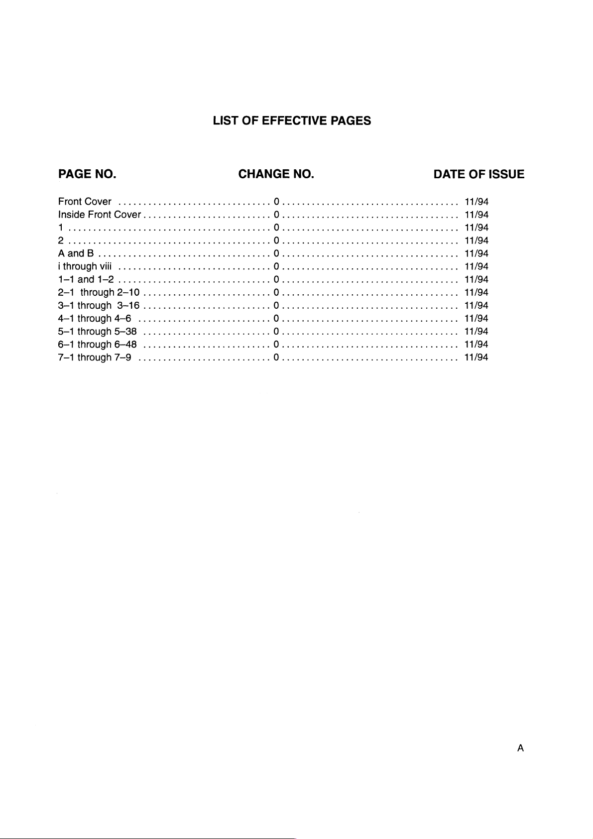
LIST
OF
EFFECTIVE
PAGES
PAGE
Front
Cover
Inside
T
2
А
апаВ
|
through
1-1
and
2-1
through
3—1
through
4—1
through
5—1
through
6--1
through
7—1
through
NO.
...............................
Front
Cover..........................
.............
viit
...............................
1—-2...............................
2-10
.......................... O aa
3-16
..........................
4-6
...........................
5-38
.......................... O aaa
6-48
.......................... O aa
7-9
...........................
еее
CHANGE
ениьнья
NO.
O
0....................................
가
O
O
ea
O
0....................................
0......
O....................................
O
O
ε
1...
ρω ω εν
aa
DATE
εν ον ο εν
aa
00000
OF
ον
ων
11/94
11/94
11/94
11/94
11/94
11/94
00 이 11/94
11/94
11/94
11/94
11/94
11/94
11/94
ISSUE

(This
page
is
intentionally
left
blank.)
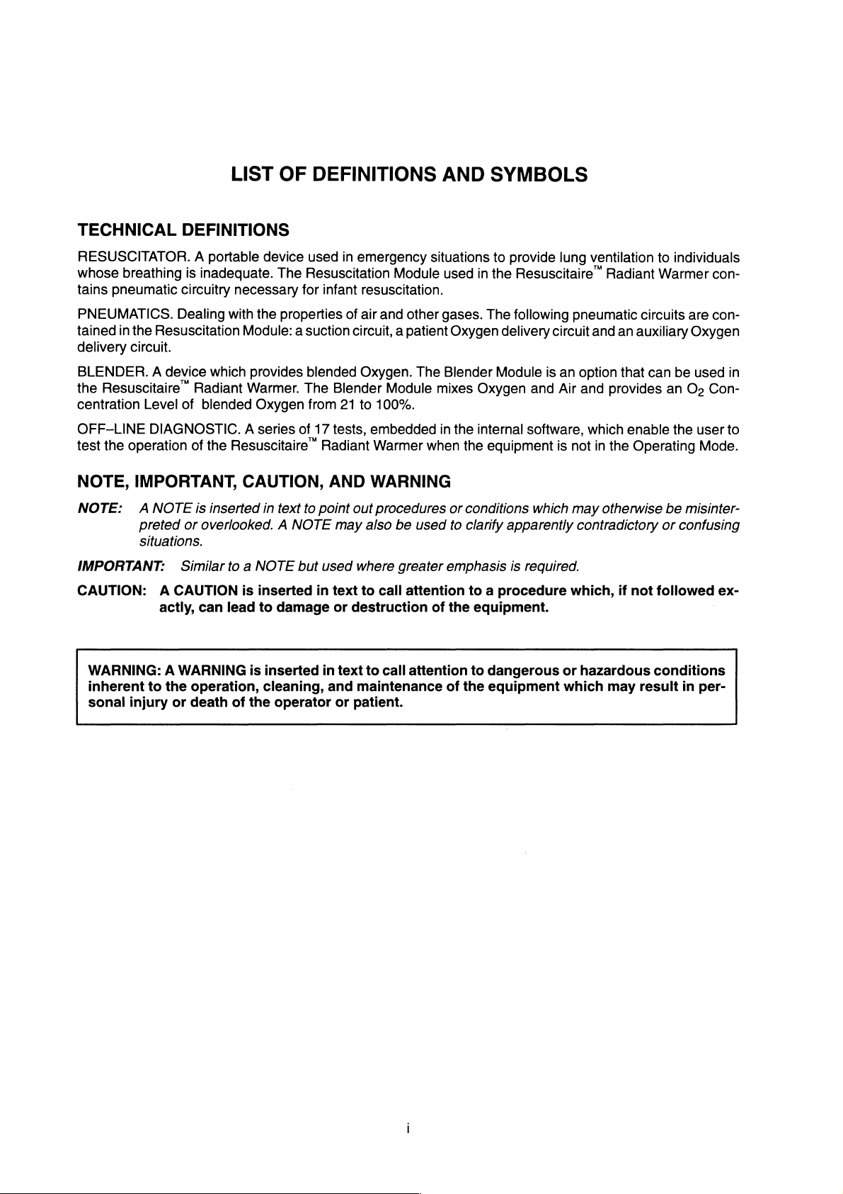
LIST
OF
DEFINITIONS
AND
SYMBOLS
TECHNICAL
RESUSCITATOR.
whose
tains
PNEUMATICS.
tained
delivery
breathing
pneumatic
in
the
circuit.
DEFINITIONS
A
is
inadequate.
circuitry
Dealing
Resuscitation
BLENDER. A device
the
Resuscitaire”
centration
OFF-LINE
test
the
operation
NOTE,
IMPORTANT,
NOTE: © A
preted
Level
DIAGNOSTIC.
NOTE
Radiant
of
blended
of
is
or
overlooked. A NOTE
situations.
IMPORTANT:
CAUTION:
Similar
A
CAUTION
actly,
can
portable
device
The
necessary
with
the
properties
Module: a suction
which
provides
Warmer.
Oxygen
A
series
the
Resuscitaire”
CAUTION,
inserted
in
to a NOTE
is
inserted
lead
to
text
damage
used
in
emergency
Resuscitation
for
infant
resuscitation.
of
air
circuit, a patient
blended
The
from
of
17
to
point
but
in
Oxygen.
Blender
21
to
tests,
Radiant
AND
out
may
used
where
text
to
or
destruction
100%.
embedded
Warmer
WARNING
procedures
also
Module
and
Module
be
greater
call
situations
used
other
gases.
Oxygen
The
Blender
mixes
in
the
when
or
used
to
emphasis
attention
of
the
to
provide
in
the
Resuscitaire”
The
following
delivery
Module
Oxygen
internal
the
equipment
conditions
clarify
to a procedure
and
software,
which
apparently
is
required.
equipment.
lung
ventilation
pneumatic
circuit
and
is
an
option
Air
and
which
is
not
in
may
otherwise
contradictory
which,
Radiant
circuits
an
auxiliary
that
can
provides
enable
the
Operating
if
not
to
individuals
Warmer
are
Oxygen
be
used
an
Os
Con-
the
user
Mode.
be
misinter-
or
confusing
followed
con-
con-
in
to
ex-
WARNING: A WARNING
inherent
sonal
to
injury
the
operation,
or
death
of
is
the
inserted
cleaning,
operator
in
and
text
or
patient.
to
call
attention
maintenance
of
the
to
dangerous
eguipment
or
hazardous
which
may
conditions
result
in
per-
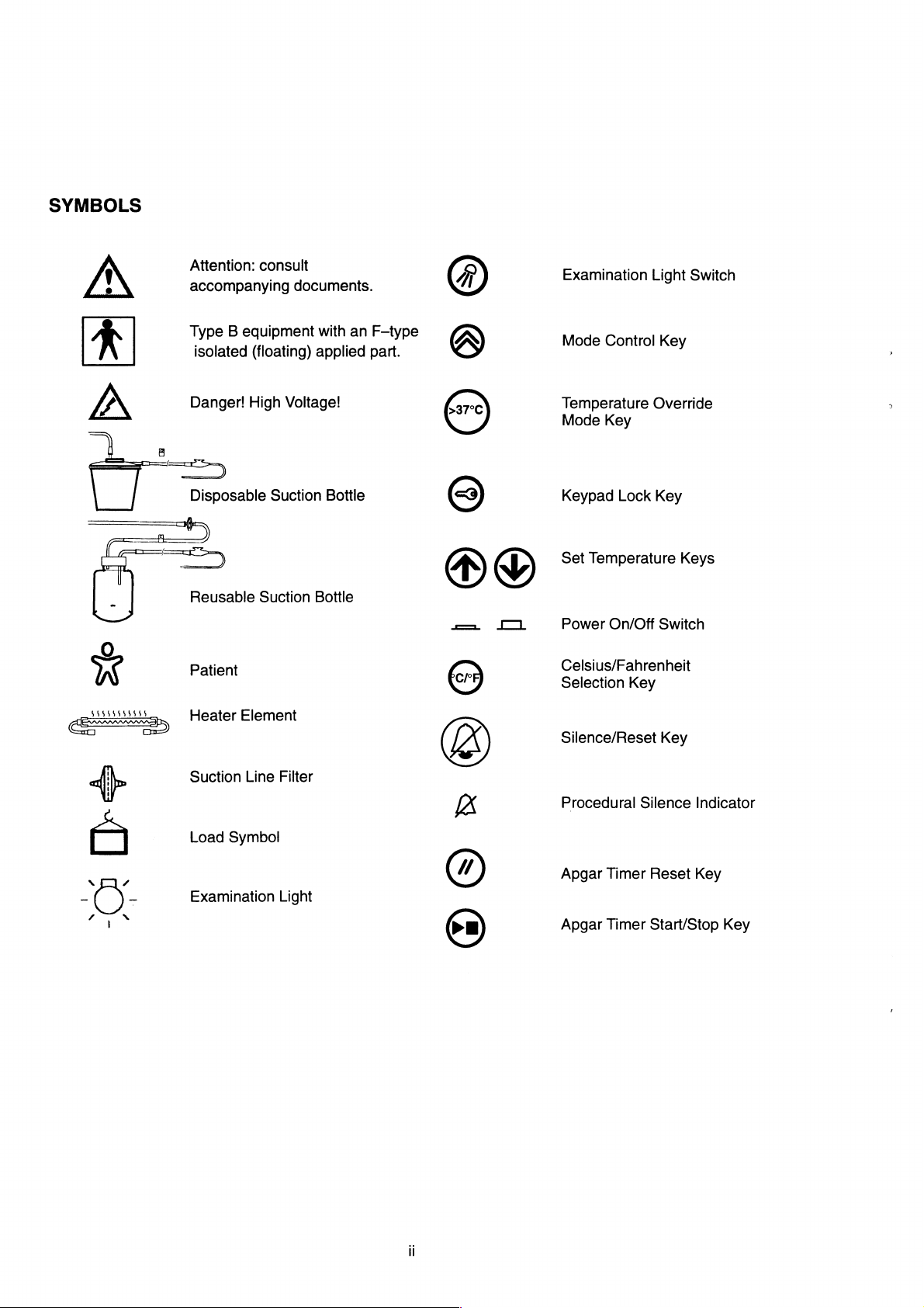
SYMBOLS
[>
>»
>
0
W
1408444584
diz
號
Attention:
accompanying
Type B equipment
isolated
Danger!
B
DI
Disposable
一 一 一
|
一
=
Reusable
Patient
Heater
Suction
Load
Symbol
consult
(floating)
High
Voltage!
Suction
Suction
Element
Line
Filter
documents.
with
an
applied
Bottle
Bottle
F-type
part.
©
©
À
©
®
1
©
©
&
Examination
Mode
Temperature
Mode
Keypad
Set
Temperature
Power
Celsius/Fahrenheit
Selection
Silence/Reset
Procedural
Light
Control
Override
Key
Lock
On/Off
Key
Silence
Key
Key
Keys
Switch
Key
Switch
Indicator
ー
N
O)
/
Apgar
Timer
Reset
Y
一
N
Examination
Light
©
Apgar
Timer
Key
Start/Stop
Key
®
TABLE
OF
CONTENTS
(cont.)
SECTION
5.8
TROUBLESHOOTING
5.8.1
5.8.2
5.8.3
5.8.4
5.9
REMOVAL
5.9.1
5.9.2
5.9.3
5.9.4
5.9.5
5.9.6
5.9.7
6
PARTSLIST
6.1
GENERAL
6.2 _ HEPLACEABLE
2
GENERAL
FOR
GENERAL
FORSYSTEMDIAGNOSTICCODES......................................
GENERAL
ГОН
GENERAL
FOR
AND
GENERAL
REMOVING
REMOVING
REMOVING
REMOVING
REMOVING
REMOVING
...
TROUBLESHOOTING
SYSTEM
ТНЕ
THE
ERROR
TROUBLESHOOTING
TROUBLESHOOTING
ВАОТАМТ
TROUBLESHOOTING
PNEUMATICHARDWARE
REPLACEMENT
...
cece
AND
REPLACING
THE
ELECTRICAL
AND
REPLACING
AND
REPLACING
AND
REPLACING
AND
REPLACING
PARTS,
DISPOSABLES
CODES
М/ААМЕН
PROCEDURES
GUIDELINES
..
ccc
GUIDELINES
GUIDELINES
.............
GUIDELINES
νωνωνωνωνο
.
THE
BACK
COVER
MODULE
THE
THE
THE
THE
AND
..................................
BLENDER
RESUSCITATION
GAS
SUPPLY
QUARTZ
ACCESSORIES
teen
νν
ων
ενω ο νεο
..........................
MODULE
MODULE
MODULE
HEATER
ELEMENT
ee
εν
εννοω
ων
dede
dieu
....................
..............
.................
............
eee eee
2
eee
2 2
PAGE
aaa
nee
εν
εν
εως
εν
εκ
εως
ων
ως
ue
ees
eens 6 一
ea
이이 2 이 이 이 0 이
5-28
5—28
5—29
5-31
5-32
5-34
5-34
5-34
5-35
5-35
5-36
5-37
5-37
1
6 一 1
6-1
7
DIAGRAMS
7.1
GENERAL
aaa
7
一 1
ーー 7 一
1
LIST
OF
TABLES
(cont.)
TABLES
6.14
RESUSCITAIRE™
W/O
6.1B
RESUSCITAIRE™
AUTOBREATH,
6.1C
RESUSCITAIRE™
AUTOBREATH,
6.1D
RESUSCITAIRE™
W/O
6.2
6.3
6.4
65
RESUSCITAIRE™
RESUSCITAIRE"
RESUSCITAIRE"
Oo
ASSEMBLY,
RESUSCITAIRE”
Os5/AIR
6.6
RESUSCITAIRE™
6.7.
RESUSCITAIRE”
ELECTRICAL
6.8
6.9
RESUSCITAIRE™
ASSEMBLY
PARTS
RESUSCITAIRE™
ASSEMBLY
PARTS
6.10
RESUSCITAIRE”
PARTS
6.11
RESUSCITAIRE”
PARTS
6.12
RESUSCITAIRE
PARTS
AUTOBREATH,
BLENDER
NO
AUTOBREATH,
PARTS
ASSEMBLY,
MODULE
WITHOUT
LIST
WITH
LIST
LIST
LIST
LIST
1
RADIANT
2...
RADIANT
eee
RADIANT
RADIANT
NO
BLENDER
RADIANT
RADIANT
BLENDER
RADIANT
BLENDER
RADIANT
RADIANT
RADIANT
LIST
RADIANT
PARTS
RADIANT
RADIANT
ASSEMBLY,
RADIANT
THE
RADIANT
THE
AUTOBREATH
--ἍἈ--...,
ccc
een
WARMER
PARTS
WARMER
PARTS
LIST
WARMER
PARTS
WARMER
PARTS
WARMER
WARMER
WARMER
WARMER
LIST
WARMER
WARMER
WARMER
AUTOBREATH
WARMER
WARMER
WARMER
WARMER
ASSEMBLY,
LIST
ASSEMBLY,
ASSEMBLY,
LIST
..............
ASSEMBLY,
LIST
CART
BASSINET
GAS
GAS
,,,,,,,,,
ASSEMBLY,
SUPPLY
SUPPLY
cece
BLENDER
PARTS
LIST
RESUSCITATION
INFANT
RESUSCITATION
INFANT
HEAD
PCB1
PCB2
RESUSCITATOR,
ASSEMBLY,
DISPLAY
POWER
eee...
PARTSLIST
SUB-ASSEMBLY,
cece
ccc
eee
ASSEMBLY,
RESUSCITATOR,
BOARD
AND
PARTS
MODULE
MODULE
ASSEMBLY,
CONTROL
|
nere
ω
ων
νερο
ον
ως ο ο
..................
PARTS
eee
LIST
eee
eee
eee
LIST
..............
M
BOARD
eee
ASSEMBLY,
eee
PAGE
reen
ον
ως
rene
.........
ーー
enna
eens
...,
ーー
see
6-5
6-8
6-11
6-13
6—17
6-21
6-23
6-27
6-31
6-33
6-37
6-39
6-42
6—45
6-47
Vili
RESUSCITAIRE”
GENERAL
RADIANT
INFORMATION
WARMER
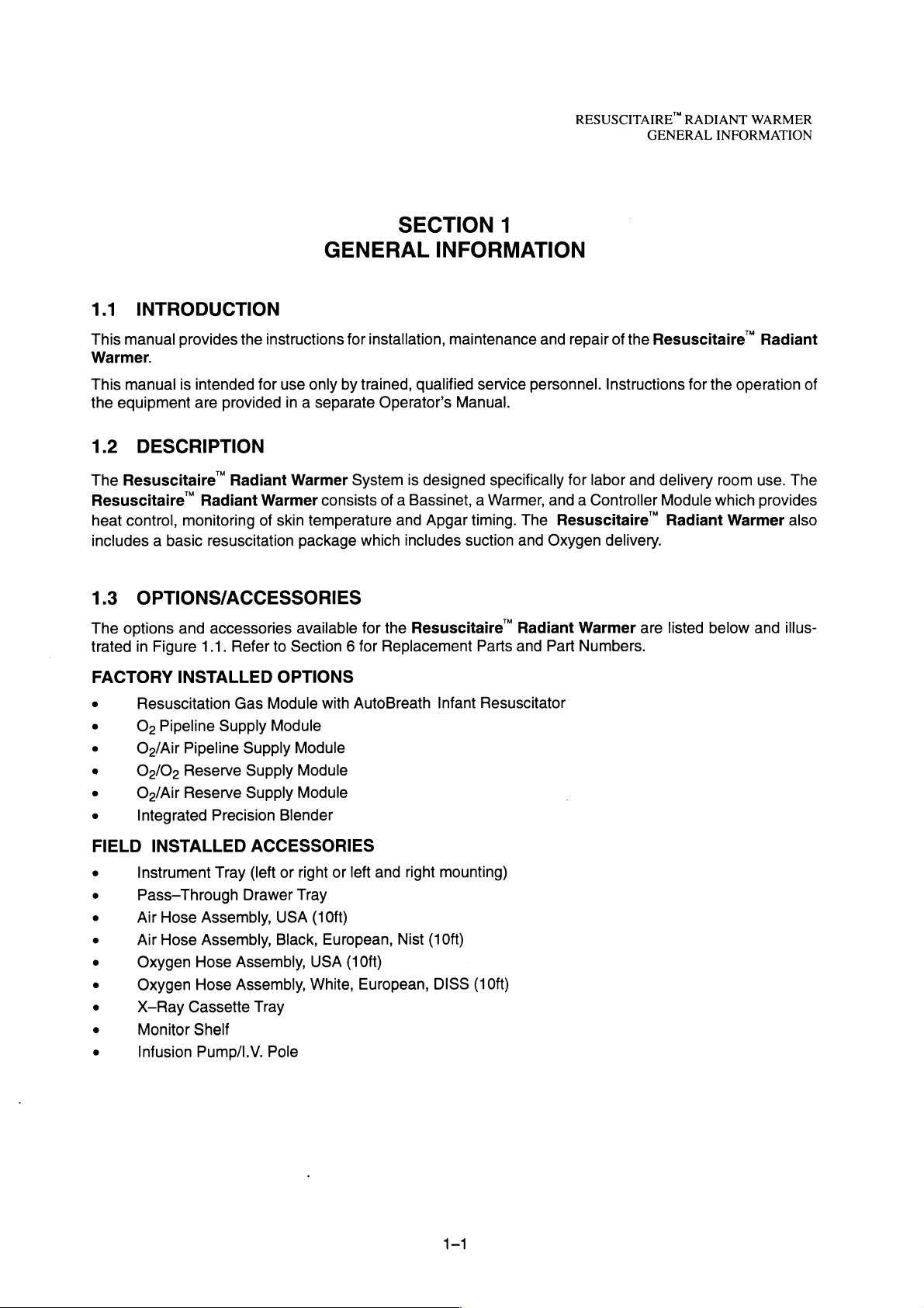
1.1
INTRODUCTION
This
manual
provides
Warmer.
This
manual
the
equipment
1.2
The
Resuscitaire”
Resuscitaire”
heat
control,
includes a basic
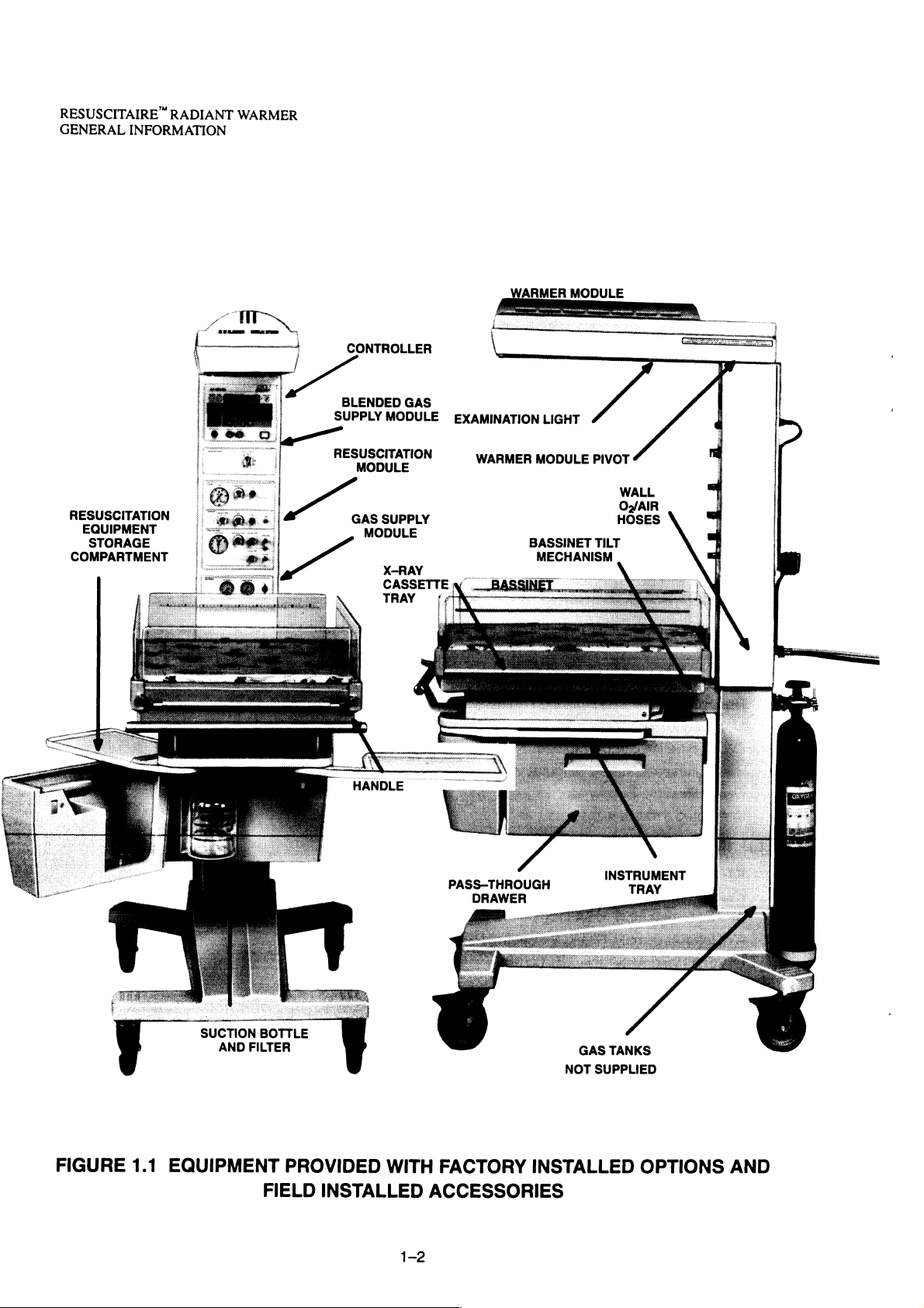
1.3
The
options
trated
is
intended
are
DESCRIPTION
Radiant
monitoring
resuscitation
OPTIONS/ACCESSORIES
and
accessories
in
Figure
1.1.
the
instructions
for
provided
Radiant
Warmer
of
Refer
GENERAL
use
only
by
in a separate
Warmer
consists
skin
temperature
package
available
to
Section 6 for
SECTION
INFORMATION
for
installation,
trained,
Operator’s
System
of a Bassinet, a Warmer,
and
which
for
the
Replacement
maintenance
qualified
Manual.
is
designed
Apgar
includes
suction
Resuscitaire”
1
service
timing.
Parts
personnel.
specifically
The
and
Radiant
and
and
repair
of
the
Instructions
for
labor
and
and a Controller
Resuscitaire”
Oxygen
Part
delivery.
Warmer
Numbers.
are
Resuscitaire “ Radiant
for
the
operation
delivery
Module
Radiant
listed
room
which
Warmer
below
use.
The
provides
also
and
illus-
of
FACTORY
9
Resuscitation
o
O»
‧
O»/Air
9
05/05
ο
O»/Air
o
Integrated
FIELD
o
Instrument
ο
Pass—Through
ο
Air
o
Air
ο
Oxygen
ο
Oxygen
o
X-Ray
o
Monitor
o
Infusion
INSTALLED
Pipeline
Pipeline
Reserve
Reserve
Precision
INSTALLED
Tray
Hose
Assembly,
Hose
Assembly,
Hose
Hose
Cassette
Shelf
Pump/I.V.
Gas
Module
Supply
Supply
Supply
Supply
ACCESSORIES
(left
Drawer
Assembly,
Assembly,
Tray
Pole
OPTIONS
Module
Module
Module
Module
Blender
or
right
Tray
USA
(10ft)
Black,
USA
White,
with
AutoBreath
or
left
and
European,
(1
Oft)
European,
right
Nist
Infant
mounting)
(10ft)
DISS
(1
Resuscitator
Oft)
1-1
RESUSCITAIRE
GENERAL
INFORMATION
RADIANT
WARMER
RESUSCITATION
EQUIPMENT
STORAGE
COMPARTMENT
CONTROLLER
BLENDED
SUPPLY
RESUSCITATION
USCITAT
GAS
GAS
MODULE
SUPPLY
MODULE
X-RAY
ARMER
EXAMINATION
WARMER
LIGHT
MODULE
BASSINET
MECHANISM
MODULE
PIVOT
TILT
WALL
Oz/AIR
HOSES
ολλ
AN I aaa
FIGURE
1.1
EQUIPMENT
SUCTION
AND
BOTTLE
FILTER
PROVIDED
FIELD
WITH
INSTALLED
PASS-THROUGH
DRAWER
FACTORY
ACCESSORIES
INSTRUMENT
GAS
TANKS
NOT
SUPPLIED
INSTALLED
TRAY
OPTIONS
AND
RESUSCITAIRE
RADIANT
INSTALLATION
WARMER
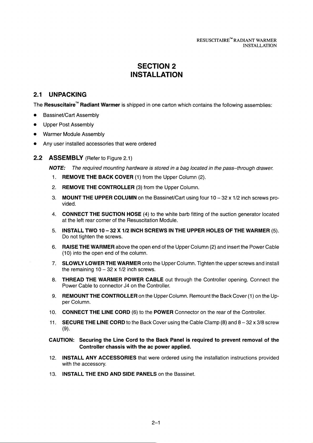
2.1
UNPACKING
The
Resuscitaire’
Bassinet/Cart
Upper
Warmer
Any
user
2.2
ASSEMBLY
NOTE:
1.
2.
3.
Post
Assembly
Module
installed
REMOVE
REMOVE
MOUNT
vided.
CONNECT
at
the
Radiant
Assembly
Assembly
accessories
(Refer
The
required
THE
THE
THE
left
rear
Warmer
to
mounting
BACK
CONTROLLER
UPPER
THE
SUCTION
corner
is
that
Figure
COVER
COLUMN
of
the
SECTION
INSTALLATION
shipped
were
2.1)
hardware
HOSE
Resuscitation
ordered
(1)
from
(3)
from
on
the
(4)
in
one
is
stored
the
the
Bassinet/Cart
to
the
2
carton
in a bag
Upper
Upper
white
Module.
which
located
Column
Column.
using
barb
fitting
contains
in
(2).
four
of
the
following
the
pass—through
10 — 32 x 1/2
the
suction
generator
assemblies:
drawer.
inch
screws
pro-
located
INSTALL
Do
RAISE
(10)
SLOWLY
the
THREAD
Power
REMOUNT
per
10.
CONNECT
11.
SECURE
(9).
CAUTION:
12.
INSTALL
with
13.
INSTALL
TWO
not
tighten
THE
into
the
LOWER
remaining
THE
Cable
Column.
THE
THE
Securing
Controller
ANY
the
accessory.
THE
10 — 32 X 1/2
the
screws.
WARMER
open
end
THE
10 — 32 x 1/2
WARMER
to
connector
THE
CONTROLLER
LINE
LINE
CORD
the
chassis
ACCESSORIES
END
AND
above
of
the
WARMER
J4 on
CORD
Line
SIDE
INCH
the
column.
inch
POWER
(6)
to
the
Cord
with
SCREWS
open
onto
screws.
CABLE
the
Controller.
on
the
to
the
Back
to
the
the
ac
that
were
PANELS
end
the
Upper
POWER
Cover
Back
power
on
IN
THE
of
the
Upper
Upper
out
through
Column.
Connector
using
Panel
applied.
ordered
the
Bassinet.
UPPER
Column
Column.
Remount
the
Cable
is
required
using
HOLES
(2)
Tighten
the
Controller
on the
Clamp
the
installation
the
the
to
OF
and
upper
Back
rear
(8)
prevent
insert
opening.
of
and 8 —
THE
WARMER
the
Power
screws
and
Connect
Cover
(1)
on
the
Controller.
32 x 3/8
removal
instructions
(5).
Cable
install
the
the
Up-
screw
of
the
provided
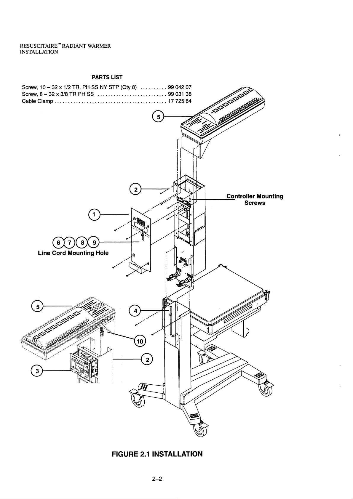
RESUSCITAIRE”
INSTALLATION
RADIANT
WARMER
PARTS
Screw,
10 — 32 x 1/2
Screw, 8 —
Cable
32 x 3/8
Clamp
..........................................
TR,
TR
PH
PHSS
SS
NY
..........................
000€
Line
Cord
Mounting
Hole
LIST
STP
(Qty
8)
..........
99
99
17
042
031
725
07
38
64
Controller
Mounting
Screws
FIGURE
2.1
INSTALLATION
2.3
OPERATIONAL
CHECKOUT
PROCEDURE
RESUSCITAIRE”
—
CONTROLLER
RADIANT
INSTALLATION
WARMER
WARNING:
CAUTION:
WARNING:
proved
tacle
1.
Box
2.
3.
The
HEAVY
cient
CONNECT
for
for
CHECK
Turn
the
ER.
NOTE:
CHECK
should
Warmer
EQUIPMENT - To
strength
THE
Connect
the
hospital—use
this
device.
THE
POWER
On
the
Power
audible
The
alarm
Unit
Circuitry
THE
SELF-TEST
be
initiated
should
are
AC
power
and
Switch
should
must
becomes
and
not
be
prevent
required
LINE
CORD
cord
of
the
correct
FAILURE
on
sound.
be
connected
active.
FUNCTION.
the
following
used
if
the
injury
to
adequately
TO
THE
only
to a properly
voltage.
ALARM.
the
Front
Turn
Off
to
should
Controller
or
POWER
DO
Turn
Panel.
the
the
ac
line
Turn
occur:
damage
control
grounded
NOT
Off
the
The
Power
for
at
On
the
fails
to
function
to
the
the
Warmer
CONNECTOR
use
extension
CIRCUIT
Power
Switch
least
Fail
and
three
Power
Warmer,
during
on
wall
receptacle
cords
BREAKER
Indicator
turn
on
minutes
Switch.
as
described
two
persons
transport.
the
Rear
or
on
should
the
CIRCUIT
before
The
Self—Test
Panel.
that
an
ac
the
Rear
come
the
below.
of
suffi-
is
ap-
Recep-
Panel.
on
and
BREAK-
Power
Fail
Function
4.
5.
e
Apgar
e
All
e
All
e
The > 37
e
All
e
The
e
The
e
The
‘When
Warm
CHECK
Power
(60%)
CHECK
Manual
Press
Arrow
the
Skin
Timer,
Alarm
Mode
ten
Indicators
Indicators
°C
segments
Procedural
Keypad
audible
the
Self-Test
Mode.
THE
PRE-WARM
Indicator
for
12
minutes,
THE
MANUAL
Indicator
the
Up
Arrow
key
until
all
Temp
Baby
Indicator
of
Silence
Lock
Switch
alarm
will
Function
should
then
should
Key
the
Heater
Probe
Connector,
Temperature
(with
the
exception
light.
lights.
the
Heater
Power
Indicator
lights.
sound a high
is
complete,
MODE.
display
MODE.
10
reduce
Select
segments
to 3 segments
light.
until
all
the
Power
the
and
Set
of
Indicator
lights.
pitch
tone, a low
the
The
Pre-Warm
(100%)
Manual
Heater
Power
Indicators
Baby
Temperature
Temperature
the
Power
light.
pitch
Controller
(30%).
Mode
are
Off.
should
Indicator
for
three
by
pressing
Display
Connect
Display
Digital
Fail
indicator)
tone,
should
minutes,
segments
the
Displays
then a beep—beep—beep.
begin
be
the
Mode
are
Skin
should
show
light.
operating
On
reduce
lit.
in
and
the
to 6 segments
Select
Press
Temperature
come
On.
all
the
eights.
the
Pre—
Heater
Key.
Down
Probe
The
to
Set
have
the
Heater
elapsed,
Power
the
Indicator
Chk
Patient
to
100%,
Indicator
all
segments
should
come
are
On
lit.
Wait
and
the
10
minutes.
audible
After
alarm
10
should
minutes
sound
RESUSCITAIRE"
INSTALLATION
RADIANT
one
time.
Wait
cond
intervals.
Power
audible
Indicators
alarm
Indicators.
CHECK
should
Press
Keypad
THE
light
the
Keypad
should
up.
WARMER
an
additional 5 minutes.
At
the
end
of 5 minutes
should
should
KEYPAD
The
be
enabled.
go
Mode
Lock
go
Off.
Off
and
LOCK.
Key,
Switch
Press
the
heater
Press
Up/Down
again.
During
this
(15
total),
the
Silence/Reset
should
the
Keypad
Arrow
The
Keypad
time
the
come
Keys
the
heater
Lock
and
Lock
audible
should
Key,
back
Switch.
the
Switch
alarm
the
On
along
°C/°F
shut
Chk
The
Key
light
should
down
Patient
with
the
Keypad
should
should
sound
at
and
the
Indicator
Heater
Lock
be
inoperative.
go
Off
30—se-
Heater
and
Power
Switch
and
the
2.4
CHECK
Indicator
Temp
Indicator
the
audible
CHECK
perature
Up
Arrow
Press
the
perature
CHECK
10.
11.
Probe
flash
CHECK
come
count
CHECK
should
Connector.
and
On
should
come
MECHANICAL
CHECK
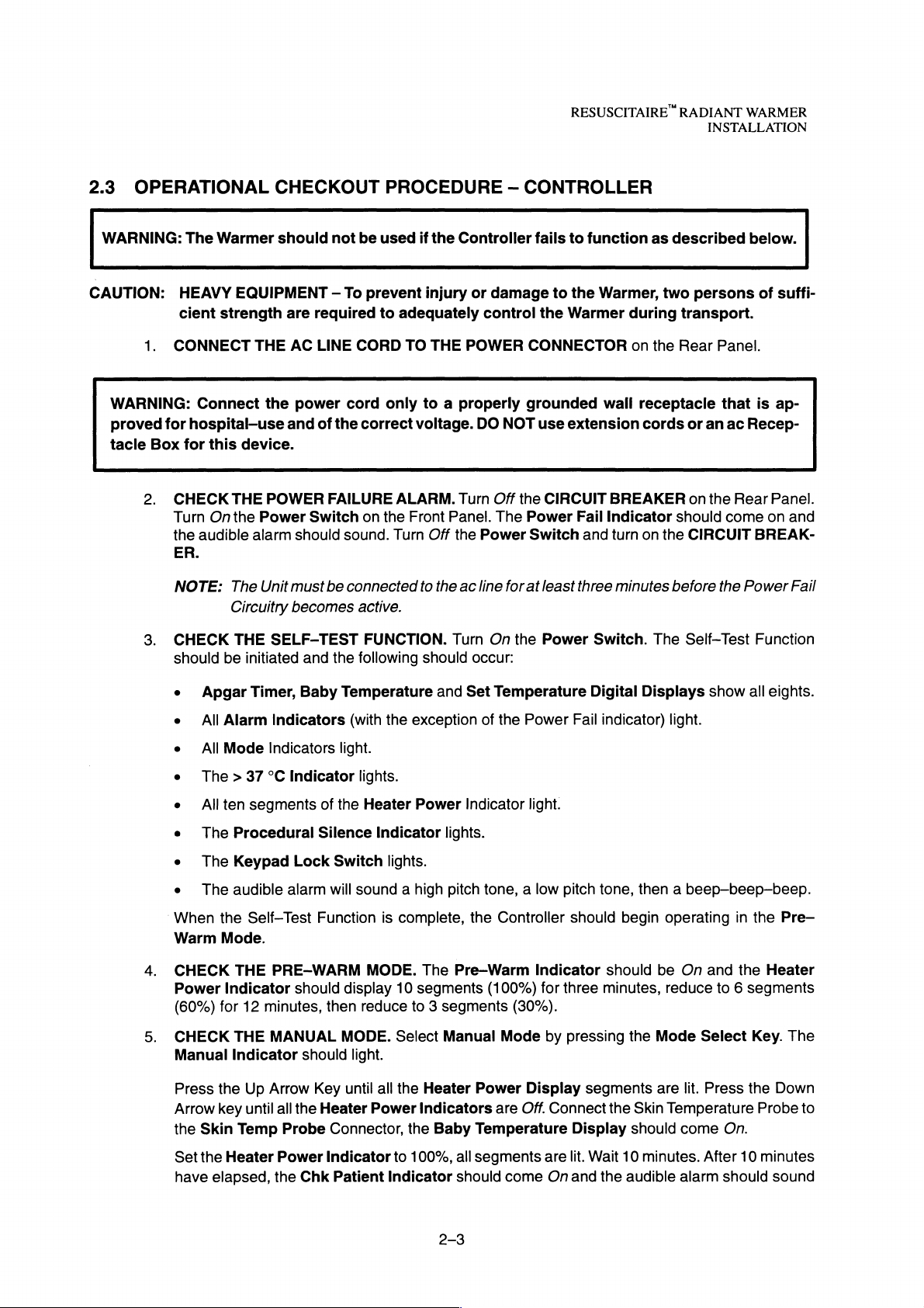
1.
bottom
Place
the
the
level
THE
BABY
should
light
should
alarm
should
TEMPERATURE
to
37.0
°C.
Key
again
Down
Arrow
falls
below
THE
PROBE
the
audible
THE
APGAR
and
begin
stop.
THE
EXAMINATION
on.
Press
CHECKOUT
THE
MATTRESS
rear
of
the
Bassinet
position.
MODE.
and
the
flash
go
OVERRIDE
Press
to
raise
Key
37.0
°C,
ALARM.
The
Baby
alarm
TIMER.
to
count
Press
the
the
TILT
Bassinet
in
the
5—degree
Select
Baby
Set
Temperature
and
the
audible
Off,
the
Baby
the
>37
°C
the
Set
Temperature
to
lower
the
the
>37
Disconnect
Temperature
should
sound.
Press
up
from
zero
Reset
Key,
LIGHT.
Exam
Light
CONTROL
while
supporting
and
Mode
Temp
MODE.
Key,
Set
°C
Indicator
the
Start
seconds.
the
Press
Switch
(Figure
then
by
pressing
Display
alarm
should
Indicator
Press
the
the
>37
°C
to
38.0
Temperature
should
the
Skin
Temperature
Display
should
/Stop
Press
Apgar
the
the
the
Timer
Exam
again,
2.2)
rear
lower
10—degree
the
should
sound.
should
Up
Arrow
Indicator
°C.
to
below
go
Off.
go
Off,
Key,
the
the
Start/Stop
Display
Light
Switch.
the
Examination
by
pulling
edge
tilt
position.
Mode
Select
activate.
Press
the
become
Key
should
37.0
°C.
Probe
the
Probe
Apgar
Timer
Key,
should
The
Light
up on
the
of
the
Bassinet
Return
Key.
The
In
addition,
the
Silence/Reset
steady
to
raise
come
When
from
the
On.
the
On.
the
Skin
Set
Press
Set
Indicator
Display
the
Apgar
go
Off.
Examination
should
lever,
located
with
the
Bassinet
go
the
Baby
Baby
Key,
Tem-
the
Tem-
Temp
should
should
Timer
Light
Off.
at
the
palm.
to
L
2—4
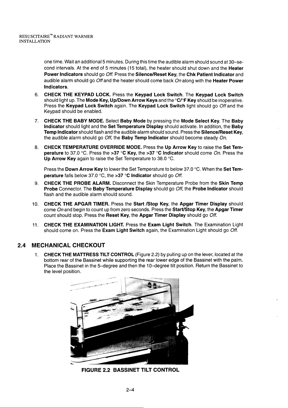
2.
CHECK
straight
engaged
THE
BASSINET
down.
to
confine
FIGURE
SIDE
Return
the
the
panel
infant.
2.3
CHECKING
PANELS
by
reversing
THE
(Figure
2.3)
the
procedure.
BASSINET
RESUSCITAIRE”
by
raising
Check
SIDE
PANELS
each
that
RADIANT
panel.
the
panel
WARMER
INSTALLATION
Pivot
it
to
hang
is
positively
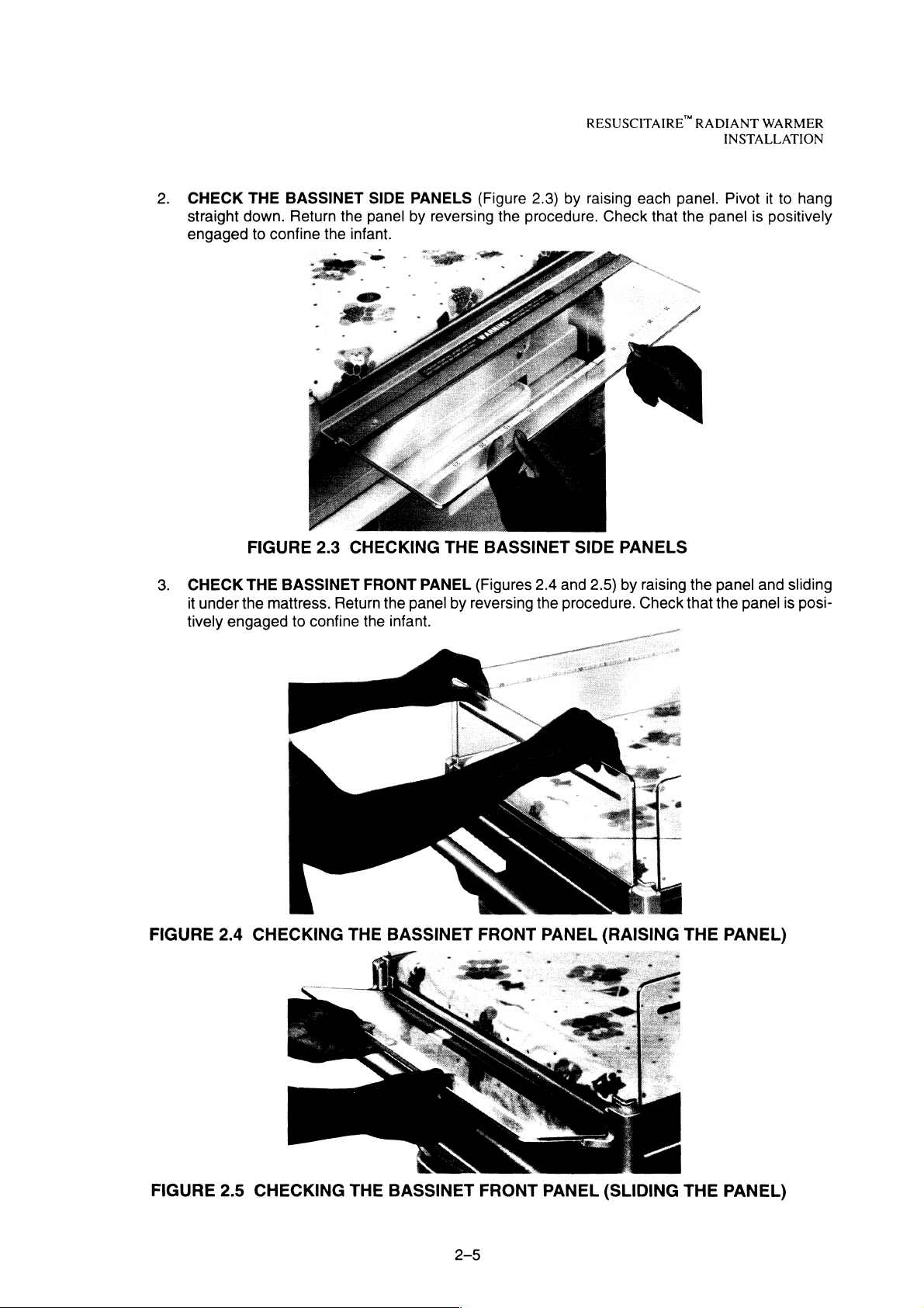
3.
CHECK
it
tively
FIGURE
under
engaged
2.4
THE
BASSINET
the
mattress.
to
confine
CHECKING
FRONT
Return
the
THE
PANEL
the
panel
infant.
BASSINET
(Figures
by
reversing
FRONT
2.4
and
the
procedure.
PANEL
2.5)
by
raising
Check
(RAISING
the
that
THE
panel
the
panel
PANEL)
and
sliding
is
posi-
FIGURE
2.5
CHECKING
THE
BASSINET
FRONT
ον
PANEL
(SLIDING
THE
PANEL)
RESUSCITAIRE”
INSTALLATION
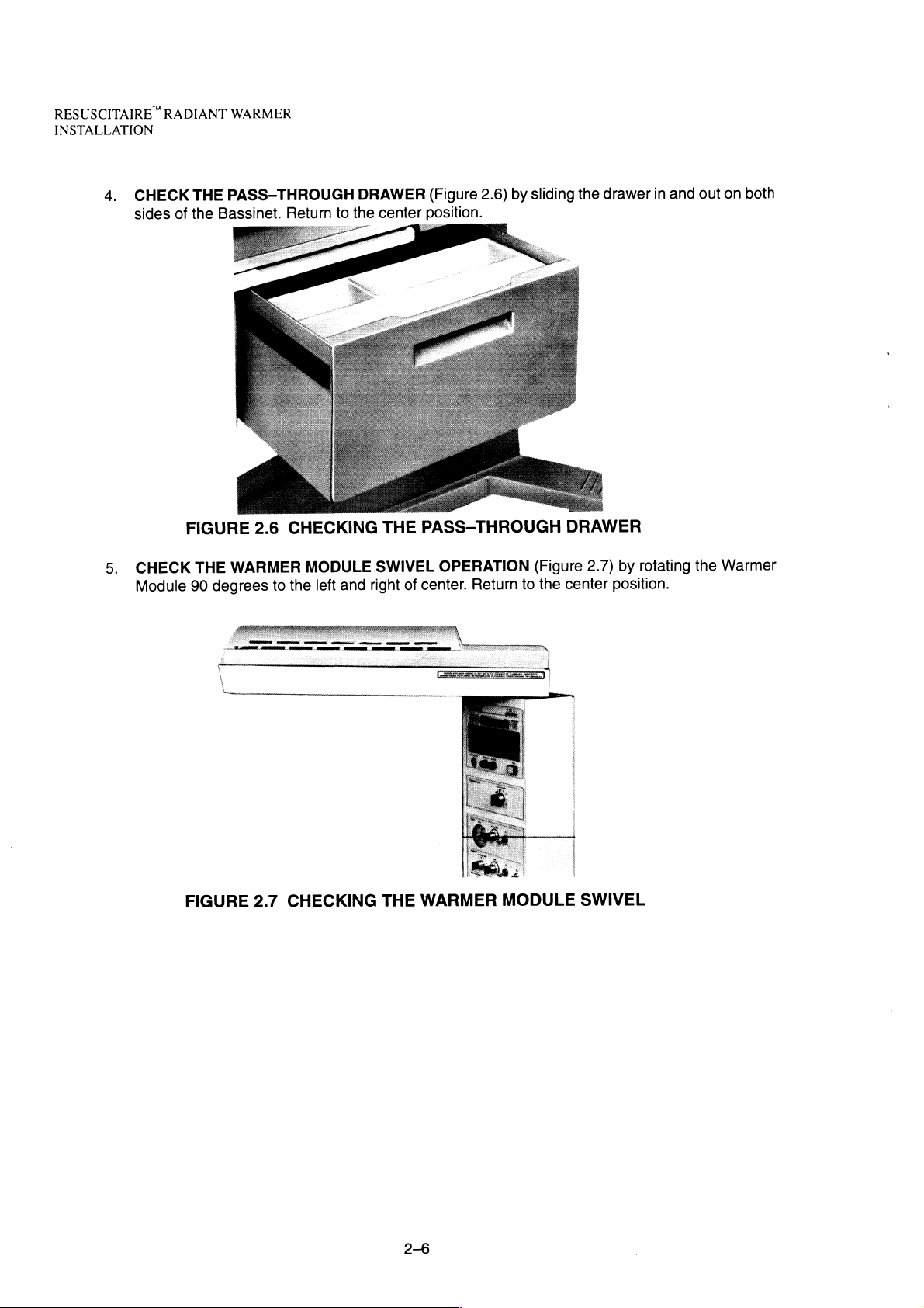
4.
RADIANT
CHECK
sides
of
THE
the
WARMER
PASS-THROUGH
Bassinet.
Return
to
the
NS
SS
DRAWER
center
ο
à
AS
(Figure
position.
2.6)
by
sliding
the
drawer
in
and
out
on
both
5.
CHECK
Module
FIGURE
THE
90
2.6
WARMER
degrees
FIGURE
2.7
CHECKING
MODULE
and
left
the
to
CHECKING
THE
SWIVEL
of
right
THE
PASS-THROUGH
OPERATION
center.
WARMER
Return
(Figure
the
to
MODULE
DRAWER
by
2.7)
center
position.
SWIVEL
rotating
the
Warmer
2-6
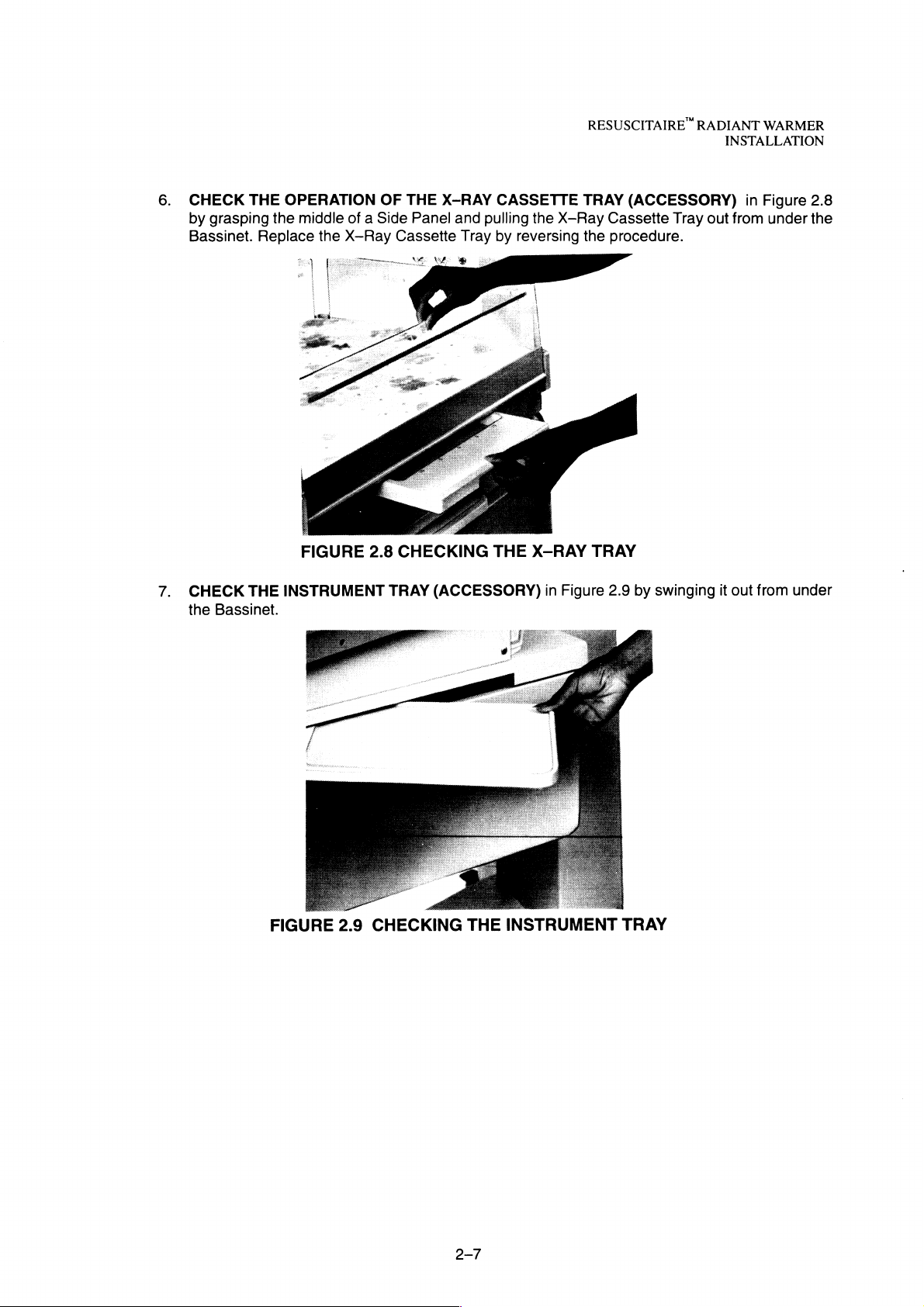
6.
CHECK
by
grasping
Bassinet.
THE
OPERATION
the
middle
Replace
the
FIGURE
OF
of a Side
X-Ray
2.8
THE
X-RAY
Panel
and
Cassette
CHECKING
pulling
Tray
CASSETTE
the
by
reversing
THE
X-RAY
RESUSCITAIRE
TRAY
X-Ray
the
TRAY
(ACCESSORY)
Cassette
procedure.
RADIANT
Tray
INSTALLATION
in
out
from
WARMER
Figure
under
2.8
the
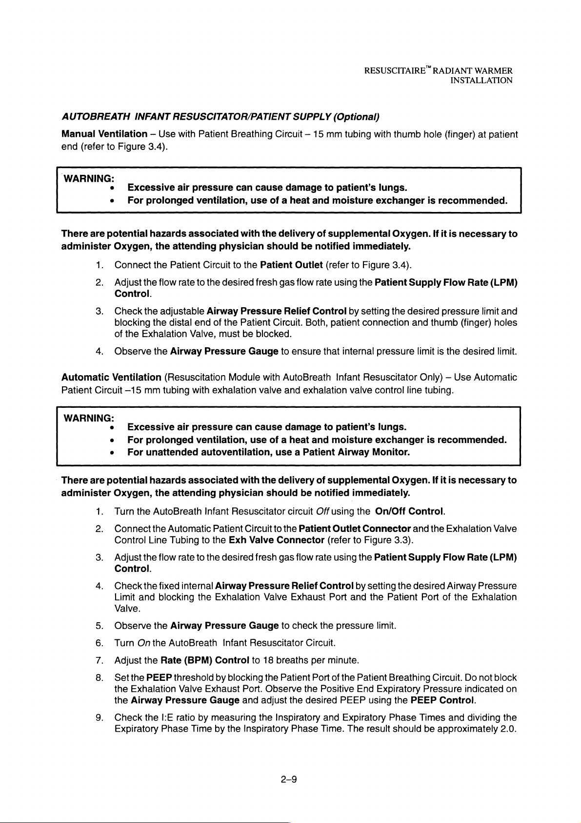
7.
CHECK
the
Bassinet.
THE
INSTRUMENT
TRAY
(ACCESSORY)
in
Figure
2.9
by
swinging
it
out
from
under

RESUSCITAIRE"
INSTALLATION
2.5
RESUSCITATION
RADIANT
WARMER
EQUIPMENT
PRE-USE
CHECKOUT/SET-UP
SUPPLY
If
using
PRESSURE
1.
Reserve
2.
3.
4.
BLENDED
1.
SUCTION
1.
2.
Ensure
the
Ensure
and
Examinethe
that a sufficient
Set
GAS
If
er
Check
connected
Ensure
nection
that
Oo
unit
and
that
Gas
Supply
that
cylinder(s)
that
the
cylinder
appropriate
the
Gas
Supply
SUPPLY
applicable,
Control
set
Knob.
that a clean
in
the
that a bacterial
to
the
(Optional)
reusable
Disposable
(and
AIR)
pipeline(s)
the
gas
supply
from
cylinders:
is(are)
valve
Cylinder
reserve
the
gas
On/Off
Precision
Suction
Resuscitation
filter
Suction
present
properly
located
Pressure
supply
Switch
Blender
Bottle
(reusable
Equipment
(reusable
Bottle.
are
secured
on
the
is
present.
to
the
to
Suction
securely
is
40
to
in
top
of
Gauges
On
position.
the
desired
or
disposable,
Storage
Bottle)
attached
75
psi.
the
the
cylinder
Oxygen % Concentration
Compartment
to
mounting
on
the
front
Figure
is
connected
appropriate
yokes
is
open.
of
the
2.10)
at
the
in-line
Reusable
fittings
on
the
Upper
is
installed
front
with
on
rear
of
Column
using
of
the
the
the
the
to
the
and
properly
Warmer.
supply
rear
Warmer
ensure
Blend-
con-
of
NOTE:
The
3.
4.
5.
6.
7.
/
disposable
Connect
the
free
of
the
Bassinet.
Turn
Onthe
Block
the
Min/Max
nitude
to
Turn
Offthe
Connect
2.10.
Extension
a
of
TZ
Suction
bottle
has a built-in
FIGURE
the
desired
end
of
Suction
Patient
Control
the
desired
Suction
the
desired
the
extension
Outlet
while
2.10
CHECKING
extension
On/Off
of
the
viewing
maximum
On/Off
suction
catheter
tubing
tubing
Switch.
Suction
the
suction
Switch.
Tube
Catheter
filter.
to
in
either
Bottle.
suction
to
the
THE
the
outlet
tubing
Adjust
level
pressure
distal
/
SUCTION
of
the
retaining
the
on
the
value.
end
of
BOTTLE
Suction
suction
Suction
the
extension
Extension
Tube
Bottle
slot
provided
magnitude
Gauge.
Outlet
Adjust
tubing
Suction
Port
on
the
using
the
as
shown
/
Catheter
and
secure
Front
Panel
the
Suction
suction
in
Figure
mag-
RESUSCITAIRE
RADIANT
INSTALLATION
WARMER
AUTOBREATH
Manual
end
(refer
WARNING:
There
are
administer
Automatic
Patient
Circuit
WARNING:
INFANT
Ventilation — Use
to
Figure
e
e
potential
Oxygen,
1.
Connect
2.
Adjust
3.4).
Excessive
For
prolonged
hazards
the
the
the
flow
Control.
3.
4.
Check
blocking
of
Observe
the
the
Exhalation
adjustable
the
the
Ventilation
—-15
mm
tubing
e
Excessive
e
For
prolonged
e
For
unattended
RESUSCITATOR/PATIENT
with
Patient
air
pressure
ventilation,
associated
attending
Patient
rate
to
distal
end
Valve,
Airway
(Resuscitation
with
air
pressure
ventilation,
Breathing
can
use
with
physician
Circuit
Airway
to
the
desired
of
the
must
Pressure
the
Pressure
Patient
be
Gauge
Module
exhalation
can
use
autoventilation,
Circuit — 15
cause
damage
of a heat
the
delivery
should
Patient
fresh
gas
Relief
Circuit.
blocked.
to
with
AutoBreath
valve
and
cause
damage
of a heat
use a Patient
SUPPLY
mm
to
and
of
be
notified
Outlet
flow
(refer
rate
Control
Both,
ensure
that
exhalation
to
and
(Optional)
tubing
with
patient’s
moisture
supplemental
exchanger
immediately.
to
Figure
using
the
Patient
by
setting
patient
connection
internal
Infant
Resuscitator
valve
pressure
control
patient’s
moisture
Airway
exchanger
Monitor.
thumb
lungs.
Oxygen.
3.4).
the
lungs.
hole
is
recommended.
If
Supply
desired
and
thumb
limit
is
Only) — Use
line
tubing.
is
recommended.
(finger)
it
is
necessary
Flow
Rate
pressure
(finger)
the
desired
Automatic
at
patient
(LPM)
limit
holes
to
and
limit.
There
are
administer
1.
2.
3.
4.
9.
potential
Oxygen,
Turn
the
Connectthe
Control
Adjust
Control.
Check
Limit
Valve.
Observe
M
Turn
Onthe
Adjust
NO
Set
the
O
the
Exhalation
the
Airway
Check
Expiratory
hazards
the
AutoBreath
Automatic
Line
Tubing
the
flow
the
fixed
and
blocking
the
AutoBreath
the
Rate
PEEP
Pressure
the
I:E
Phase
associated
attending
Infant
to
rate
to
the
internal
the
Airway
Pressure
(BPM)
threshold
Valve
Exhaust
ratio
by
Time
with
physician
Resuscitator
Patient
the
Circuit
Exh
desired
Airway
Exhalation
Infant
Control
by
blocking
Port.
Gauge
measuring
by
the
and
Inspiratory
the
delivery
should
circuit
to
the
Valve
Connector
fresh
gas
flow
Pressure
Gauge
Resuscitator
to
Valve
to
18
breaths
the
Patient
Relief
Exhaust
check
Observe
adjust
the
the
Inspiratory
Phase
of
be
notified
Off
Patient
rate
Control
the
Circuit.
per
Port
the
Positive
desired
and
Time.
supplemental
immediately.
using
the
On/Off
Outlet
(refer
Port
minute.
of
Connector
to
Figure
using
the
by
and
pressure
the
Patient
End
PEEP
Expiratory
The
Patient
setting
the
limit.
Expiratory
using
result
Oxygen.
Control.
and
3.3).
Supply
the
desired
Patient
Port
Breathing
Pressure
the
PEEP
Phase
should
Times
be
If it
is
necessary
the
Exhalation
Flow
Rate
Airway
of
the
Exhalation
Circuit.
Do
indicated
Control.
and
dividing
approximately
to
Valve
(LPM)
Pressure
not
block
on
the
2.0.
RESUSCITAIRE”
INSTALLATION
10.
RADIANT
Check
the
WARMER
desired
Breath
Rate
by
counting
the
number
of
breath
cycles
per
minute.
AUXILIARY
1.
2.
FLOW
Connect
nector.
Adjust
(provides
the
desired
the
desired
100%
Oxygen
device
Auxiliary
to
Flow
only)
be
supplied
using
the
by
Aux
the
Auxiliary
Flow
Flow
(LPM)
Circuit
Control
to
and
the
check
Aux
Outlet
for
flow.
Con-
2-10
RESUSCITAIRE
TECHNICAL
RADIANT
INFORMATION
WARMER
SECTION
TECHNICAL
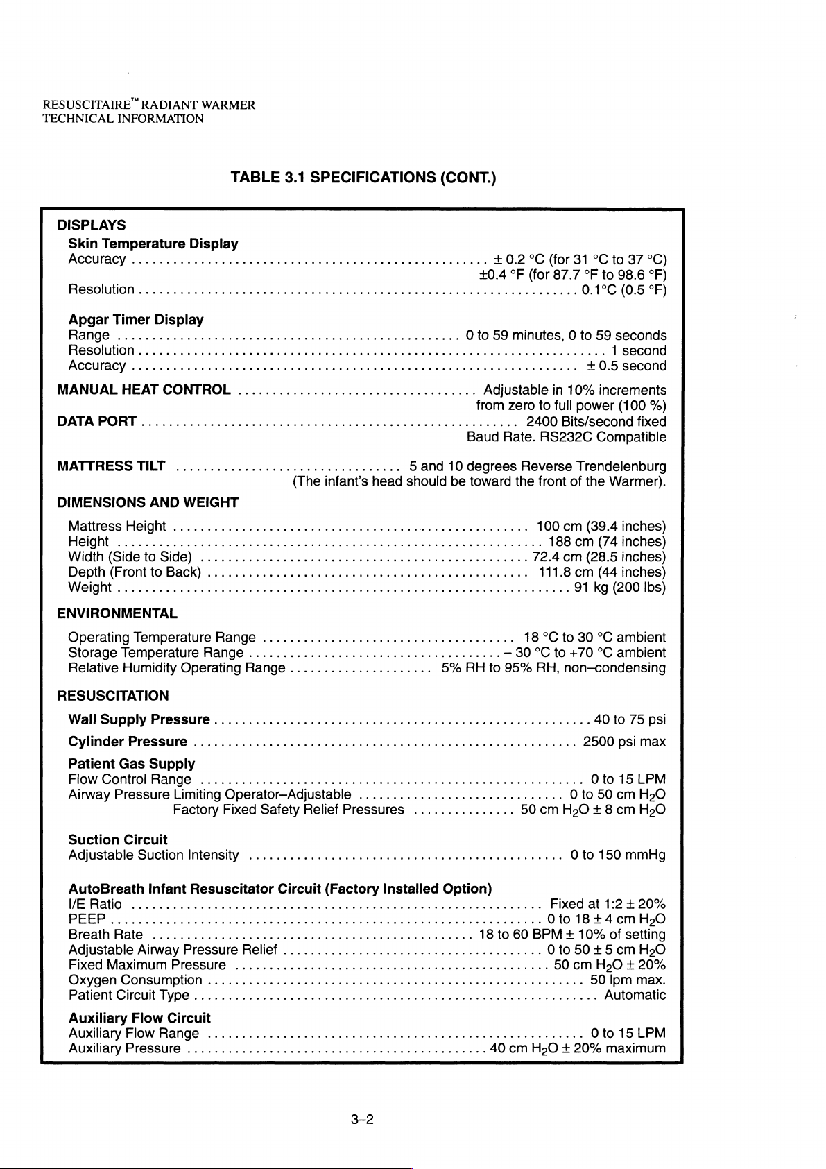
3.1
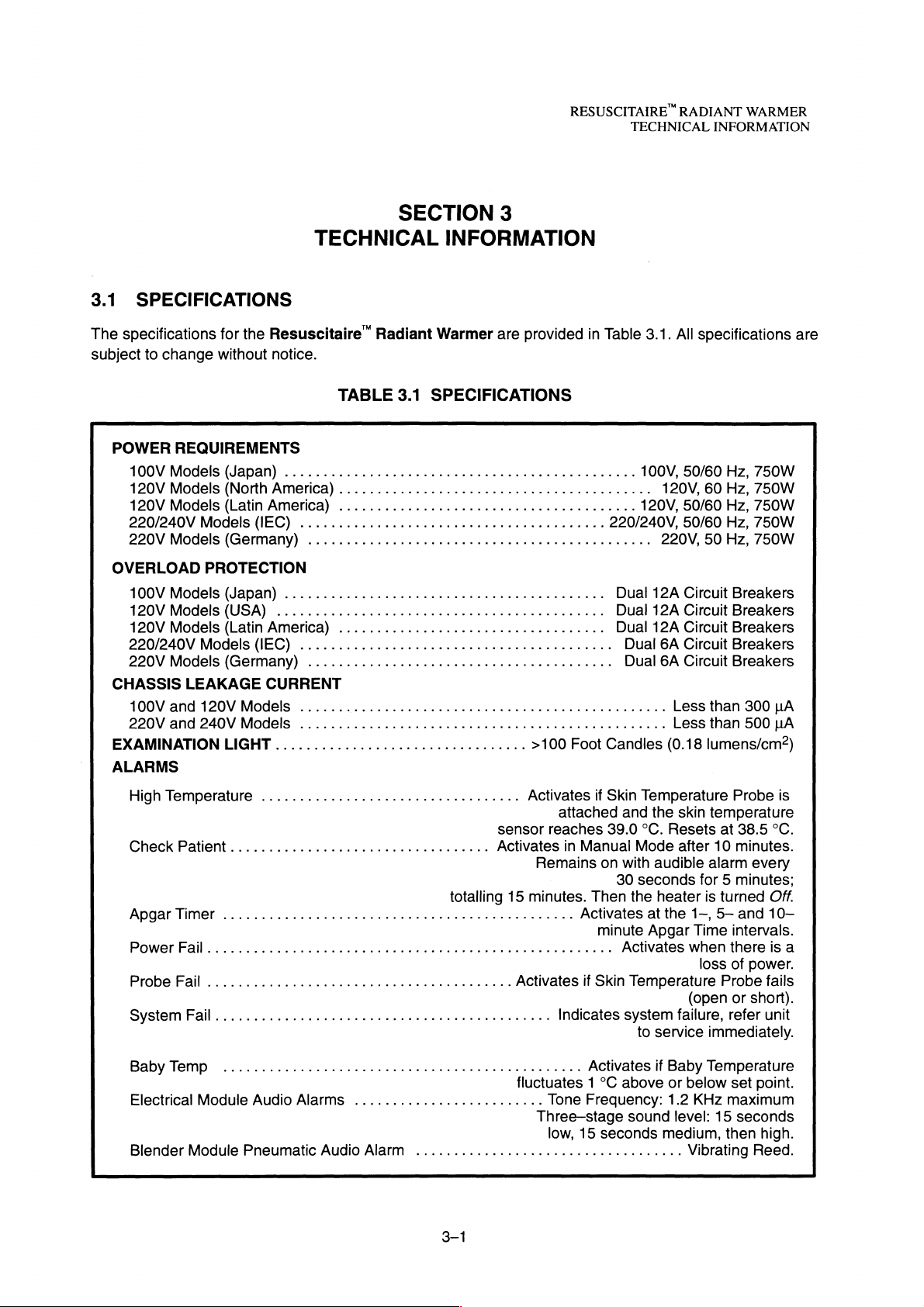
SPECIFICATIONS
The
specifications
subject
to
change
POWER
100V
Models
120V
Models
120V
Models
220/240VModels(!EC)
220VModels(Germany)
OVERLOAD
100V
Models
120VModels(USA)...........................
120V
Models
220/240V
220V
Models
CHASSIS
100V
and
220V
and
EXAMINAMONLIGHT.................................
ALARMS
for
the
without
REQUIREMENTS
(Japan)
(North
(Latin
PROTECTION
(Japan)
(Latin
Models
LEAKAGE
120V
240V
(IEC).
(Germany)
Models
Models
Resuscitaire”
notice.
America)
America)
.......................................
................................
.....................................,,...
America)
.
............
CURRENT
.......
Radiant
TABLE
.........................................
.......................................
...................................
aaa
Warmer
3.1
SPECIFICATIONS
ε
ενω
3
INFORMATION
are
provided
ενω
νε
κενο
νο
κενο
0.0
ων
ρω
εν
εν
ον
γεν ο ων
nen
>100
in
εν
εν ο ων
ーー
ος
ον
Foot
Table
3.1.
100V,
120V,
120V,
220/240V,
220V,
Dual
12A
Dual
12A
Dual
12A
Dual
6A
Dual
6A
ee
eens
Candles
All
specifications
50/60
60
50/60
Hz,
50/60
50
Hz,
Circuit
Circuit
Circuit
Circuit
Circuit
Less
than
Less
than
(0.18
lumens/cm?)
Hz,
750W
Hz,
750W
750W
Hz,
750W
750W
Breakers
Breakers
Breakers
Breakers
Breakers
300
uA
500
LA
are
High
Temperature
Check
ApgarTimer
Power
ProbeFail...................................
System
Babylemp
Electrical
Blender
Patient
Fl
Fail
............ooooooococrorrercnr
...........................
Module
Module
.................................
.
..............................
Audio
Alarms
Pneumatic
Audio
sensor
cee
eee
eee
eee
eee
Activates
totalling
erre
.........................
Alarm
.....
0...
15
ela
Activates
εν
e
fluctuates 1 °C
ccc
Activates
attached
reaches
in
Manual
Remains
minutes.
εως
Three—stage
eens
Then
Activates
이 이 Activates
if
Indicates
Activates
Tone
Frequency:
low,
15
if
Skin
and
39.0
on
with
30
the
minute
Skin
Temperature
system
above
sound
seconds
Temperature
the
skin
temperature
°C.
Resets
Mode
after
audible
seconds
heater
at
Apgar
to
service
if
alarm
for 5 minutes;
is
the
1—,
Time
when
loss
(open
failure,
immediately.
Baby
Temperature
or
below
1.2
KHz
level:
medium,
Vibrating
Probe
at
38.5
10
minutes.
every
turned
5—
and
intervals.
there
of
power.
Probe
or
short).
refer
set
point.
maximum
15
seconds
then
Reed.
is
°C.
Off.
10—
is
a
fails
unit
high.
RESUSCITAIRE"
TECHNICAL
RADIANT
INFORMATION
WARMER
3.2
3.2.1
This
of
3.2.2
THEORY
GENERAL
section
the
Resuscitaire
OVERALL
Instrument
Resuscitation
contains
Examination
Front
Push/Pull
Tray(s)
Equipment
OF
OPERATION
the
functional
Radiant
FUNCTIONAL
Radiant
。
Bassinet
Handle
Compartment
Base 一 一
Heater
Light
_
一 一 ____
description
Warmer
DESCRIPTION
———____—~
~
N
_
is
shown
SSS
and
in
=
detailed
Figure
|
t
|
q
OK
X
theory
3.1.
へ
X
X
of
operation
Warmer
Head
Electrical
Blender
Resuscitation
Gas
Supply
Module
X-Ray
Cassette
Pass-Thru
Drawer
of
the
equipment. A diagram
Module
Module
Tray
Warmer
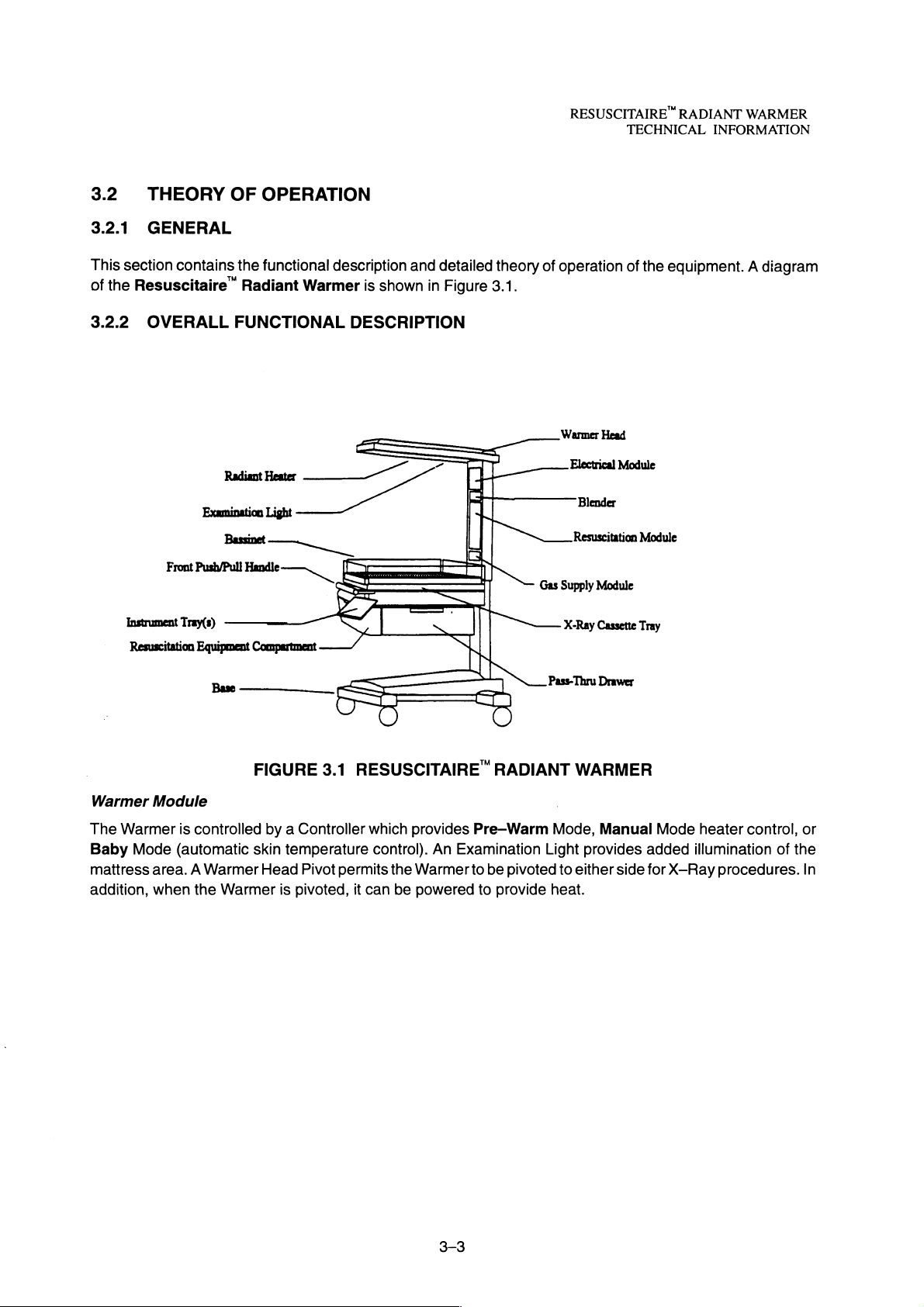
The
Warmer
Baby
Mode
mattress
addition,
Module
is
controlled
(automatic
area. A Warmer
when
the
Warmer
FIGURE
by a Controller
skin
Head
3.1
temperature
Pivot
is
pivoted,
RESUSCITAIRE
which
provides
control).
permits
it
can
the
be
Warmer
powered
Pre-Warm
An
Examination
to
to
RADIANT
be
pivoted
provide
WARMER
Mode,
Light
to
either
heat.
Manual
provides
side
Mode
added
for
X-Ray
heater
illumination
control,
procedures.
of
or
the
In
RESUSCITAIRE “ RADIANT
TECHNICAL
Bassinet
The
Bassinet
and
front
the
rear
optional
Controller
At
power-up,
firm
the
tone
is
routine
When
start
the
then
reduce
INFORMATION
is
designed
panels
at a 5
X-Ray
proper
sounded.
may
or
10
Cassette
the
operation
Also
procedures.
powered
heater
the
up,
at
heater
degree
microprocessor
the
100%
WARMER
to
provide
be
folded
angle.
Tray.
of
the
included
system
power
power
maximum
down
to
permit
Openings
within
system.
are
the
Controller
During
is a Procedural
initializes
and
to
30%.
in
the
maintain
that
function
maximum
provided
this
time,
Silence
Pre-Warm
setting
and
utility
to
aid
access
performs a series
all
Timer
for
to
on
each
displays
to
block
Mode.
three
the
infant.
side
and
out
In
the
minutes,
in
the
care
The
of
the
Bassinet
of
power-up
indicators
Baby
Pre—Warm
reduce
of
the
mattress
diagnostic
are
Temp
Mode,
to
60%
newborn.
may
for
the
lighted
audible
the
for
12
The
be
tilted
insertion
and
Alarms
tests
an
of
to
audible
during
Controller
minutes
side
up
in
the
con-
will
and
When
the
The
When
digitally
The
Also
The
The
operating
power.
10
Controller
After
Chk
Patient
Apgar
minutes
operated
displayed
Timer
have
input
Keypad
included
Resuscitation
e
Blended
Resuscitation
plays
for
the
Resuscitation
e
Suction — The
um
generator
tion
level
suction
suction
the
Controller
10
minutes
Alarm
in
and
Lock
is a Procedural
Module
Gas
module
of
within
displays
elapsed
the
Baby
the
preset
Key,
when
Supply
Module
are
Module
Suction
which
is
indicated
is
turned
level
to
On
—150
in
the
Manual
operation
the
since
Mode,
infant,
Set
Silence
(optional) — The
contains
located
consists
Circuit
provides a negative
on
the
and
in
the
the
next 5 minutes
elapsed
to
Temperature.
pressed,
time
the
timer
the
Controller
automatically
renders
Timer
pneumatic
above
and
of
the
(reusable
Suction
Off
using
the
Manual
was
Gauge.
mmHg.
Mode,
Mode, a Chk
will
and
sounds
activated.
utilizes a Skin
adjust
the
Up/Down
to
block
out
Blended
circuitry
to
the
rear
following
or
pressure
components:
disposable)
Suction
On/Off
Switch. A fixed
the
operator
cause
an
audible
the
heater
Baby
Gas
Supply
necessary
of
the
(vacuum)
may
Patient
the
heater
Temperature
output
Arrows
Temp
provides
Bassinet.
is
driven
for
be
can
adjust
Alarm
to
shut
dual
tone
of
and
Select
audible
for
infant
by a gas
suctioning
adjusted
internal
the
heater
occurs.
to
alert
Probe,
the
Failure
down.
the
connected
Warmer
Mode
alarms
blended
during
|
Oxygen
resuscitation.
powered
the
patient’s
using
the
relief
valve
power
operator
Module
Keys
inactive
routine
from
Controls
venturi
airway.
Suction
limits
from 0 to
to
acknowledge
that
1,5,
between
to
maintain
or
active.
procedures.
21
to
100%.
and
actuated
The
Control.
the
maximum
full
and
the
a
dis-
vacu-
suc-
The
3-4
 Loading...