

Air-Shields Resuscitaire RW82-1 User manual
RESUSCITAIRE®
MODEL
SERVICE
RW82-1
RADIANT
WARMER
5.9
5.9.1
The
Off-Line
the
user
Panel.
NOTE:
The
individual
ELECTRICAL
OFF-LINE
Diagnostic
can
sequence
The
number
Display,
ENTRY
with
test
functions
To'access
t
and | keys.
NOTE:
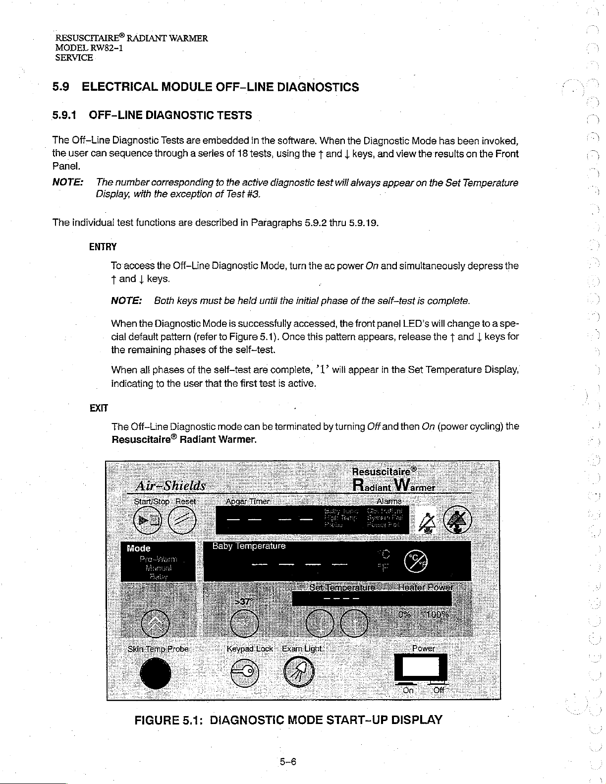
When
the
cial
default
the
remaining
When
indicating
MODULE
DIAGNOSTIC
Tests
are
through a series
corresponding
the
exception
are
the
Off-Line
Both
keys
Diagnostic
pattern
phases
all
phases
to
the
of
user
OFF-LINE
TESTS
embedded
of
to
the
of
Test
described
Diagnostic
must
be
Mode
(refer
to
of
the
the
self-test
that
the
in
the
18
tests,
active
diagnostic
#3.
in
Paragraphs
Mode,
held
until
is
successiully
Figure
5.1).
self-test.
are
complete,
first
test
DIAGNOSTICS
software.
using
turn
the
Once
is
active.
When
the t and | keys,
test
will
5.9.2
thru
the
ac
power
initial
phase
accessed,
this
pattern
’1”
will
the
the
Diagnostic
always
5.9.19.
On
of
the
front
appears,
appear
Mode
and
view
the
appear
and
self-test
panel
on
simultaneously
is
LED's
release
in
the
Set
has
been
invoked,
results
the
on
Set
Temperature
the
depress
complete.
will
change
to a spe-
the t and | keys
Temperature
Display,
Front
the
for
EXIT
The
Off-Line
Resuscitaire®
Diagnostic
Radiant
mode
can
Warmer.
be
terminated
by
turning
Offand
then
On
(power
cycling)
the
FIGURE
5.1:
DIAGNOSTIC
MODE
5-6
START-UP
DISPLAY
RESUSCITAIRE®
RADIANT
MODEL
WARMER
RW82-1
SERVICE
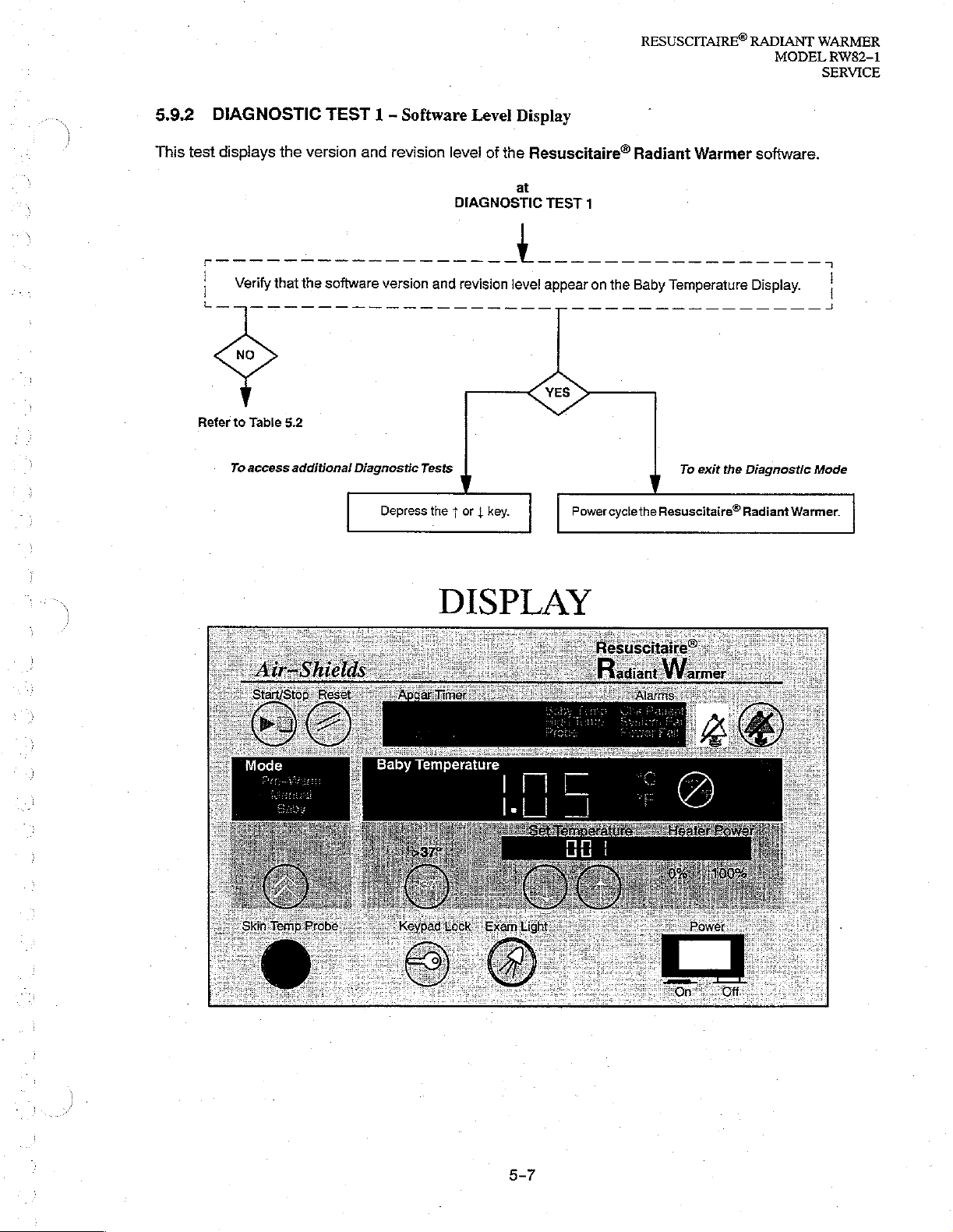
5.9.2
This
test
DIAGNOSTIC
displays
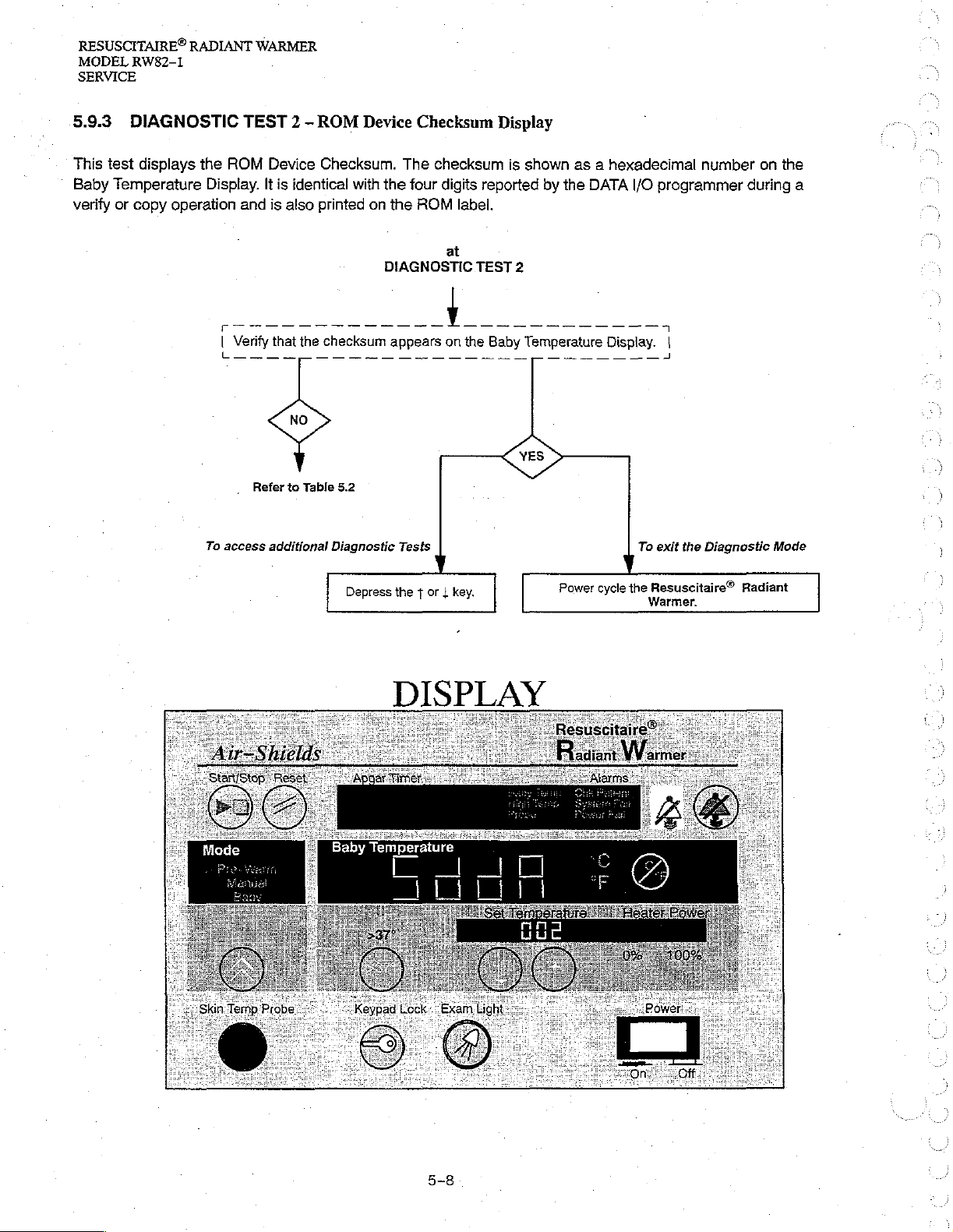
Refer
to
Table
To
access
TEST 1 -
the
version and
5.2
additional
revision
Diagnostic
Depress
Software
level
DIAGNOSTIC
Tests
the + or { key.
Level
of
the
Display
Resuscitaire®
at
TEST
1
Power
cycle
Radiant
To exit the
the
Resuscitaire®
Warmer
software.
Diagnostic
Radiant
Warmer.
Mode
DISPLAY
RESUSCITAIRE®
MODEL
SERVICE
RW82-1
RADIANT
WARMER
5.9.3
This
test
Baby
Temperature
verify
or
DIAGNOSTIC
displays
copy
the
Display.
operation
To
TEST
ROM
and
[
Verify
上
access
2 -
ROM
Device
Device
It
is
that
一 一 一
Refer
additional
is
identical
also
printed
the
一
to
Table
Checksum.
with
on
checksum
5.2
Diagnostic
Checksum
The
checksum
the
four
digits
the
ROM
at
DIAGNOSTIC
appears
Tests
on
Display
reported
label.
TEST
the
Baby
is
shown
by
the
2
Temperature
as a hexadecimal
DATA
I/O
programmer
Display.
To
1
exit
the
number
Diagnostic
on
during
the
a
Mode
Depress
key.
|
or
1
the
DISPLAY
Power
cycle
Resuscitaire®
the
Radiant
5-8
RESUSCITAIRE®
RADIANT
MODEL
WARMER
RW82-1
SERVICE
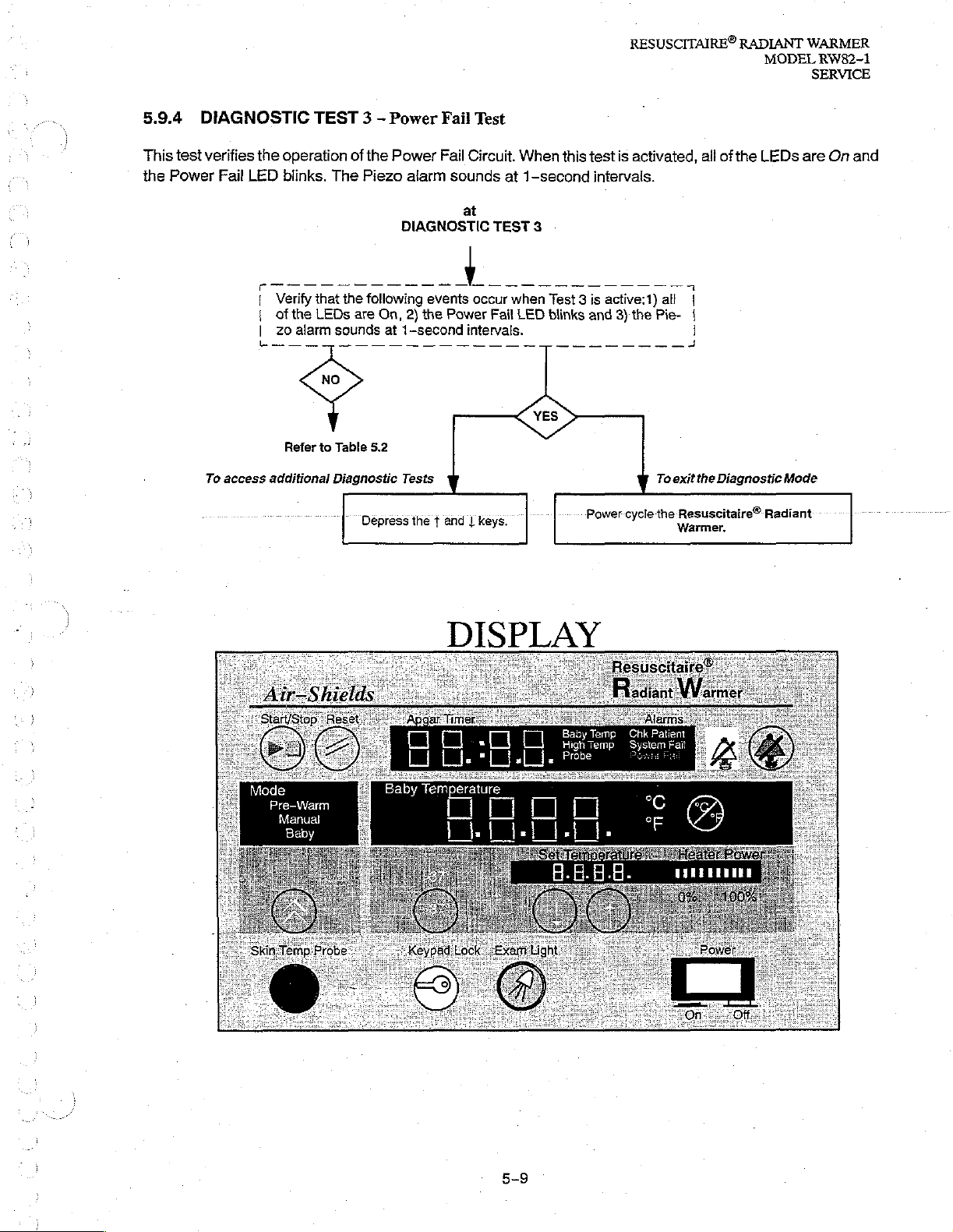
5.9.4
This
test
the
Power
DIAGNOSTIC
verifies
Fail
the
LED
M
1
Verify
1
ofthe
zo
|
蕊
To
access
additional
TEST 3 -
operation
blinks.
The
that
LEDs
alarm
一 一 一
Refer
sounds
一 一 一 一 一 一 一 一 一 一
to
Table
Diagnostic
of
the
Piezo
the
following
are
5.2
Depress
Power
Power
alarm
DIAGNOSTIC
On,
2)
at
1-second
Tests
the 1 and | keys.
Fail
Fail
sounds
events
the
Power
Test
Circuit.
at
When
at
TEST
p
occur
when
Fail
LED
intervals.
一 一 一 一 一 一
this
test
is
1-second
3
activated,
intervals.
all
of
the
LEDs
are
On
|
Test 3 is
blinks
active:1)
and
3)
the
一 一 一 一 一 一
Power-cycle
all
|
Pie-
|
|
a
To
exit the
the
Resuscitaire®
Warmer.
Diagnostic
Radiant
Mode
and
DISPLAY
5-9
RESUSCITAIRE®
MODEL
SERVICE
RW82-1
RADIANT
WARMER
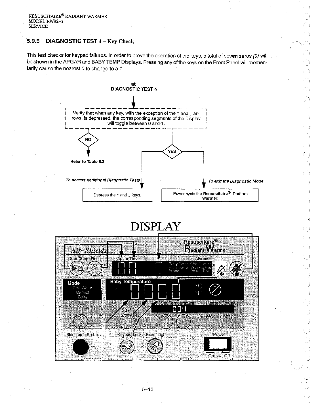
5.9.5
This
be
shown
tarily
DIAGNOSTIC
test
checks
in
the
cause
the
TEST 4 -
for
keypad
APGAR
nearest 0 to
To
Verify
rows,
Refer
access
and
that
is
to
Table
additional
Key
failures.
BABY
change
depressed,
In
TEMP
to a 7.
when
any
will
5.2
Diagnostic
Depress
the + and | keys
Check
order
to
Displays.
DIAGNOSTIC
the
toggle
at
key,
with
corresponding
between 0 and
Tests
prove
the
Pressing
TEST
the
exception
operation
4
segments
1.
of
the
any
of
the
keys
of
the t and | ar-
of
the
Display
keys, a total
on
the
Front
|
|
|
To
exit
of
the
seven
zeros
Panel
will
Diagnostic
(0)
will
momen-
Mode
Power
cycle
the
.
Resuscitaire®
Warmer.
Radiant
DISPLAY
RESUSCITAIRE®
RADIANT
MODEL
WARMER
RW82-1
SERVICE
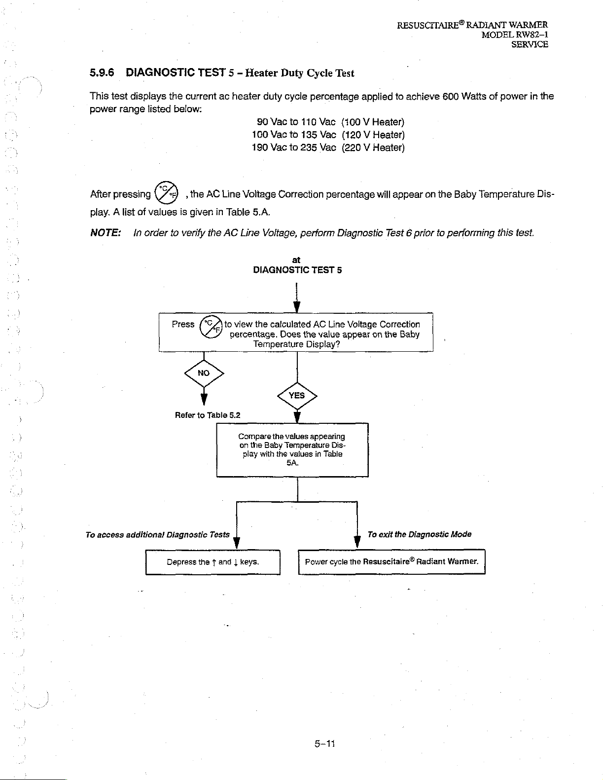
5.9.6
This
power
After
play. A list
DIAGNOSTIC
test
displays
range
pressing
of
NOTE: | In
TEST 5 -
the
current
listed
below:
,
the
AC
values
order
is
given
to
verify
the
Press
(805
Heater
ac
heater
Line
Voltage
in
Table
AC
Line
view
percentage.
Duty
duty
cycle
90
Vac
to
100
Vac
to
180
Vac
to
Correction
5.A.
Voltage,
at
DIAGNOSTIC
4
the
calculated
Does
Temperature
Cycle
Test
percentage
110
Vac
135
Vac
235
Vac
percentage
perform
TEST
AC
Line
the
value
Display?
applied
to
(100 V Heater}
(120 V Heater)
(220 V Heater)
will
appear
Diagnostic
Test 6 prior
5
Voltage
appear
Correction
on
the
achieve
Baby
600
on
the
to
performing
Watts
Baby
Temperature
of
this
power
test.
in
the
Dis-
To
access
Refer
to
Table
5.2
Compare
on
additional
Diagnostic
Depress
Tests
the $ and | keys.
the
play
Baby
with
the
the
values
appearing
Ternperature
values
in
BA.
Table
Power
Dis-
cycle
To exit the
the
Resuscitaire®
Diagnostic
Radiant
Mode
Warmer.
RESUSCITAIRE®
MODEL
RW82-1
SERVICE
RADIANT
WARMER
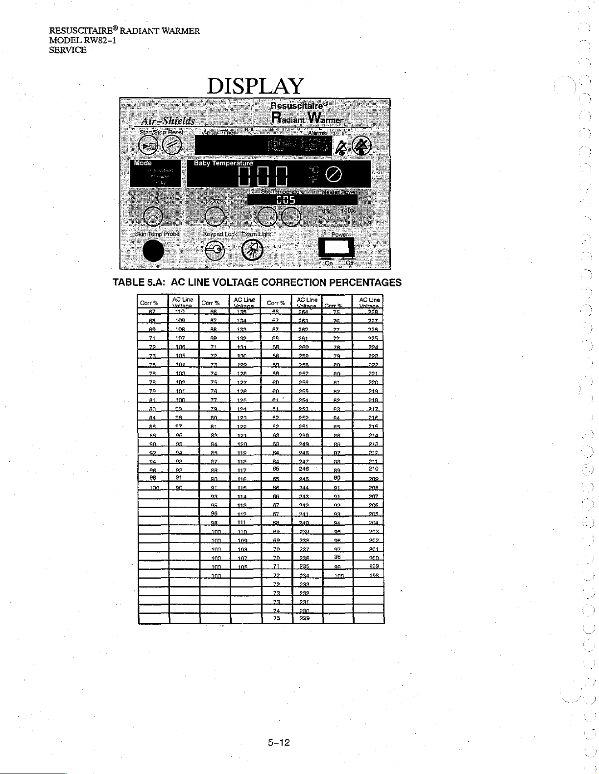
DISPLAY
TABLE
5.A:
Cor
AC
LINE
VOLTAGE
AC
Line
%
Corr % AC
CORRECTION
Line
Corr
PERCENTAGES
AC
Line
%
AC
Line
RESUSCITAIRE®
RADIANT
MODEL
WARMER
RW82-1
SERVICE
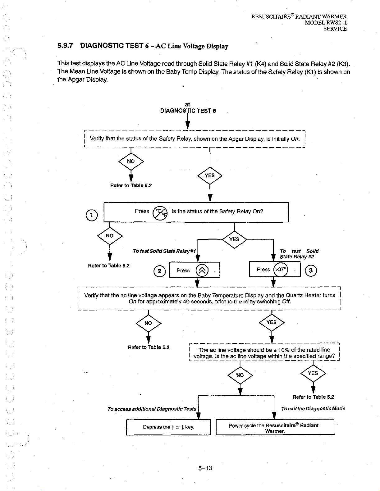
5.9.7
This
test
The
Mean
the
Apgar
DIAGNOSTIC
displays
Line
Display.
|
レーー ニ ーー
©
Voltage
Verify
the
that
ee
Refer
TEST 6 -
AC
Line
is
shown
the
status
a
to
Table
Press
Voltage
on
of
the
ee
5.2
AC
Line
read
through
the
Baby
DIAGNOSTIC
Safety
3
Is
Voltage
Temp
at
Relay,
po
a
the
status
Display
Solid
Display.
TEST
shown
on
a
of
the
State
The
6
the
Safety
Relay
status
Apgar
Relay
#1
(K4)
of
the
Display,
e
— — —
On?
and
Solid
Safety
is
initially
_
State
Relay
Off.
— — 一
(K1)
|
그
Relay
is
shown
#2
(K3).
on
|
Verify
|
Reter
°
to
Table
that
To
the
access
5.2
ac
line
On
Refer
To
test
Solid
(2)
voltage
for
approximately
to
Table
additional
Depress
State
Relay
Press
appears
5.2
Diagnostic
the
t
or
#1
Display
should
line
voltage
cycle
Press
switching
the
.
on
the
Baby
40
seconds,
|
|
Tests
|
key.
voltage.
Temperature
prior
to
the relay
The
ac
line
voltage
İs
the
ac
Power
To
State
©
and
the
Quartz
Off.
be « 10%
within
the
To
exit
Resuscitaire®
Warmer.
test
Refay
©
.
Heater
of
the
specified
Refer
the
Diagnostic
Radiant
Solid
#2
rated
range?
to
Table
turns
line
5.2
Mode
|
|
|
1
5-13
RESUSCITAIRE®
MODEL
SERVICE
RW82-1
RADIANT
WARMER
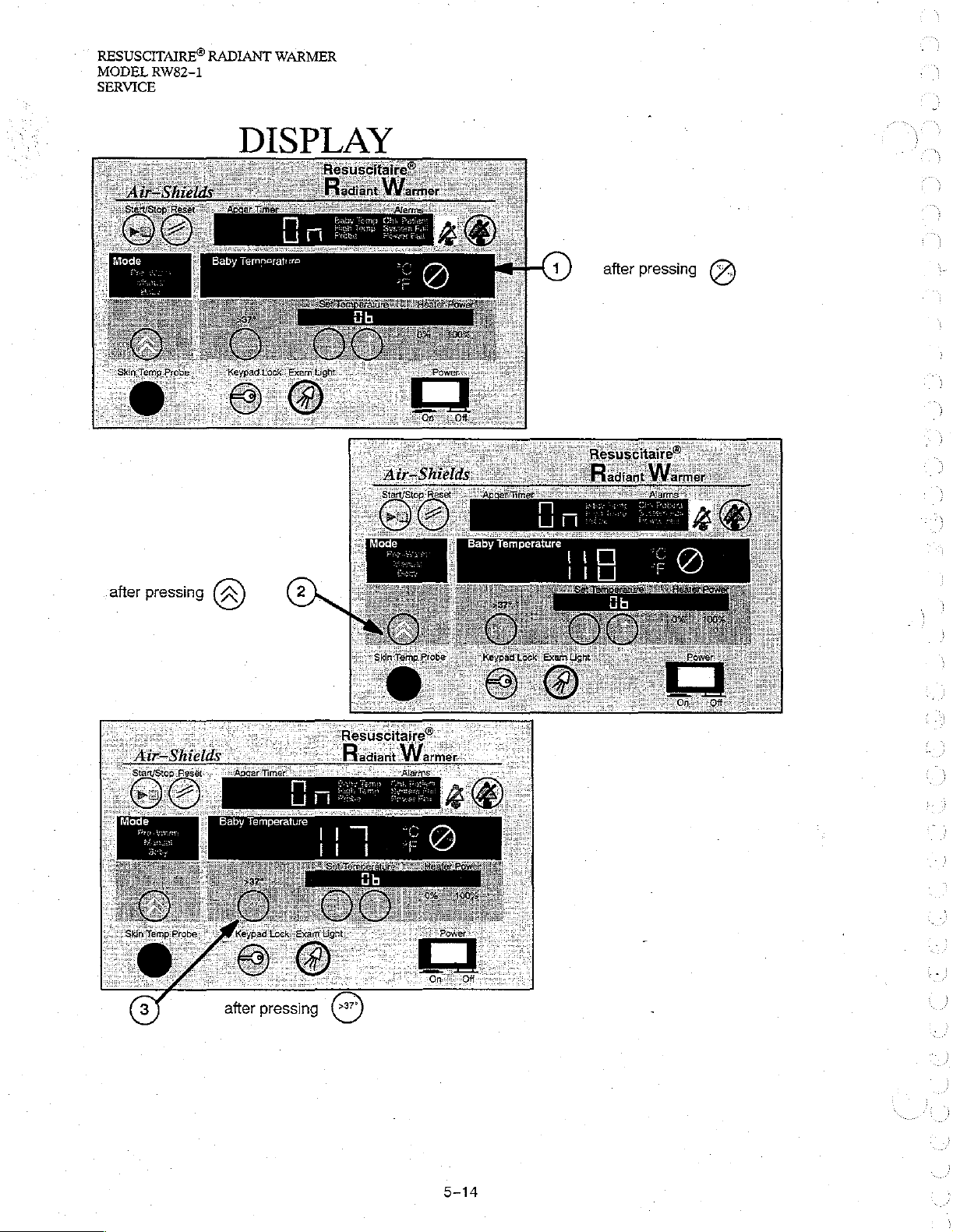
DISPLAY
|
-(1)
after
pressing
7
RESUSCITAIRE®
RADIANT
MODEL
WARMER
RW82-1
SERVICE
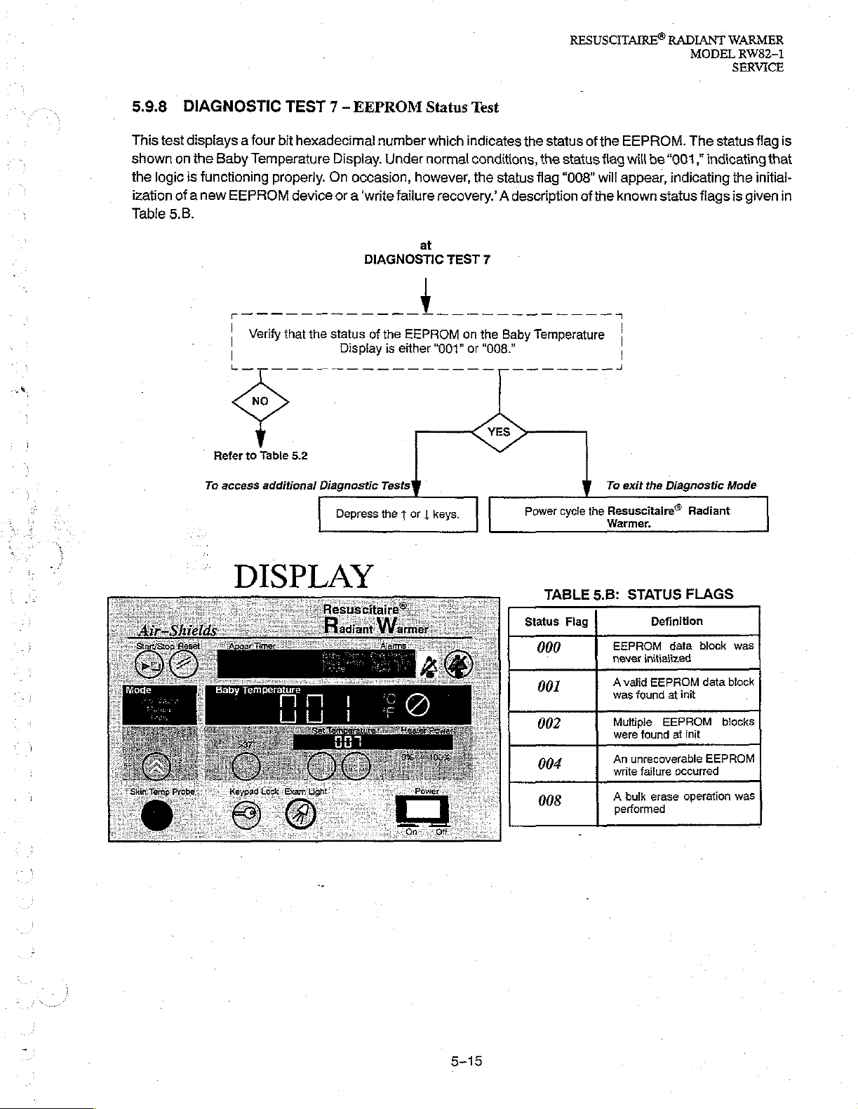
5.9.8
This
test
shown
the
ization
Table
on
logic
of
5.B.
DIAGNOSTIC
displays a four
the
Baby
Temperature
is
functioning
anew
EEPROM
Verify
|
Refer
to
Table
To
access
additional
TEST 7 -
bit
hexadecimal
properly.
that
On
device
the
status
5.2
Diagnostic
EEPROM
number
Display.
or a ‘write
Display
Depress
Under
occasion,
failure
DIAGNOSTIC
of
the
is
Tests
the t or | keys.
Status
which
normal
however,
at
EEPROM
either
Test
indicates
conditions,
the
status
recovery.’ A description
TEST
7
on
the
Baby
“001”
or
“008.”
the
status
the
status
flag
“008”
Temperature
Power
cycle
of
the
flag
will
of
the
To exit the
the
Resuscitaire®
Warmer.
EEPROM.
will
be
appear,
known
|
The
“001,”
indicating
indicating
status
flags
Diagnostic
Radiant
status
the
is
given
Mode
flag
is
that
initial-
in
DISPLAY
TABLE
Status
000
001
002
004
008
Flag
5.B:
STATUS
EEPROM
never
Avalid
was
Multiple
were
An
unrecoverable
write
A
bulk
performed
Definition
data
initialized
EEPROM
found
at
init
EEPROM
found
at
failure
occurred
erase
FLAGS
block
data
block
blocks
init
EEPROM
operation
was
was
5-15
RESUSCITAIRE®
MODEL
SERVICE
RW82-1
RADIANT
WARMER
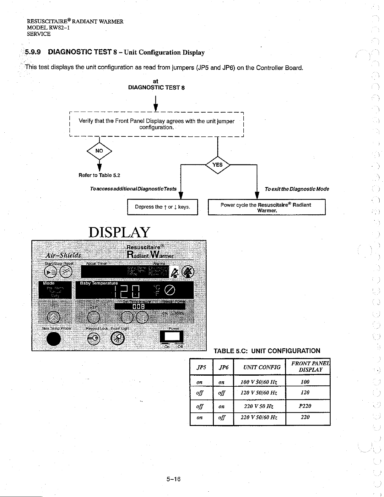
‘5.9.9
This
test
DIAGNOSTIC
displays
F
|
|
ln
the
デ ご
TEST 8 -
unit
configuration
デー
デー
デー
デー
デー デー デー
Verify
that
the
Refer
to
Table
Toaccessadditional
Unit
Front
5.2
Configuration
as
read
DIAGNOSTIC
デー
デー
ーー
Panel
Display
configuration.
DiagnosticTests
Depress
from
jumpers
at
TEST
8
ーー
デデデ
agrees
ea
the f or | keys
Display
(JP5
ーー
デーーーー
with
the
.
and
unit
JP6)
テ
ーー
jumper
Power
on
the
n
|
|
a
cycle
Controller
To
the
Resuscitaire®
Warmer,
exit
Board.
the
Diagnostic
Radiant
Mode
DISPLAY
x
TABLE
JPS | JP6
on on
off
off
on
off
on
off
5.C:
UNIT
UNİT
CONFIG | ”
100 V 50/60
120 V 50/60
220 V 50
220 V 50/60
CONFIGURATION
RO
Hz
Hz
Hz
Hz
100
120
P220
220
iY
|
RESUSCITAIRE®
RADIANT
MODEL
WARMER
RW82-1
SERVICE
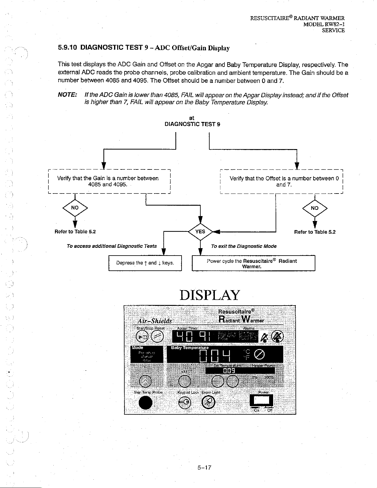
5.9.10
This
external
number
NOTE:
DIAGNOSTIC
test
displays
ADC
between
If
the
is
higher
the
reads
4085
ADC
ADC
the
and
Gain
than
TEST 9 -
probe
7,
|
Verify
that
the
Gain
is a number
4085
and
|
L
一
一 一 一 一 一
4095.
一 一 一 一 一 一 一
Gain
4095.
is
lower
FAIL
between
ADC
and
Offset
channels,
The
Offset
than
will
appear
一
一 一 一 上
Offset/Gain
on
the
probe
calibration
should
4085, FAIL
on
the
DIAGNOSTIC
|
I
at
Display
Apgar
will
Baby
and
and
be a number
appear
Temperature
TEST
9
Baby
ambient
between 0 and
on
the
|
Verify
|
一
一 一
Temperature
temperature. The
Apgar
Display
Display.
that
the
Offset
一 一 一 一 一
Display,
7.
instead;
is a number
and
7.
一 一 一 一 一
respectively.
Gain
should
and
if
the
Offset
between 0 |
一 一 一 一 一 a
The
be
4
a
|
Refer
to
To
Table
access
5.2
additional
Diagnostic
Depress
Tests
the t and | keys.
YES
DISPLAY
To
Power
exit
cycle
the
Diagnostic
the
Warmer.
Mode
Resuscitaire®
Radiant
Refer
to
Table
5.2
RESUSCITAIRE®
MODEL
SERVICE
RW82-1
RADIANT
WARMER
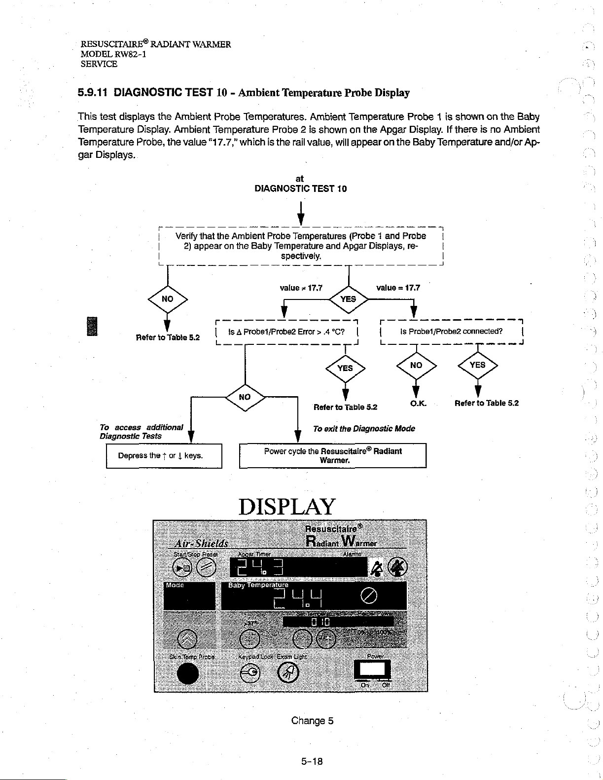
5.9.11
This
Temperature
Temperature
gar
DIAGNOSTIC
test
displays
Displays.
the
Display.
Probe,
Refer
|.
|
|
to
the
Table
TEST
Ambient
Ambient
value
Verify
2)
10 - Ambient
Probe
Temperatures.
Temperature
“17.7,”
that
appear
5.2
the
on
which
Ambient
the
Baby
Temperature
Probe 2 is
is
the
rail
at
DIAGNOSTIC
Probe
Temperatures
Temperature
spectively.
Ambient
shown
value,
TEST
and
Probe
Temperature
on
the
will
appear
10
(Probe 1 and
Apgar
Displays,
Display
Probe 1 is
Apgar
Display.
on
the
Probe
re-
K
Probe1/Probe2
ls
Baby
shown
If
there.is
Temperature
|
|
|
be1/Probe2
conne
on
the
no
and/or
ーー
cted?
Baby
Ambient
Ap-
ュ
1
To
access
Diagnostic
Depress
additional
Tests
the $ or | keys.
Refer
To
Power
cycle
the
DISPLAY
Table
to
exit
the
Diagnostic
+129
Resuscitaire
5.2
Radiant
Mode
Radi
Ok.
to
Refer
5.2
Table
Change
5
RESUSCITAIRE®
RADIANT
MODEL
WARMER
RW82-1
SERVICE
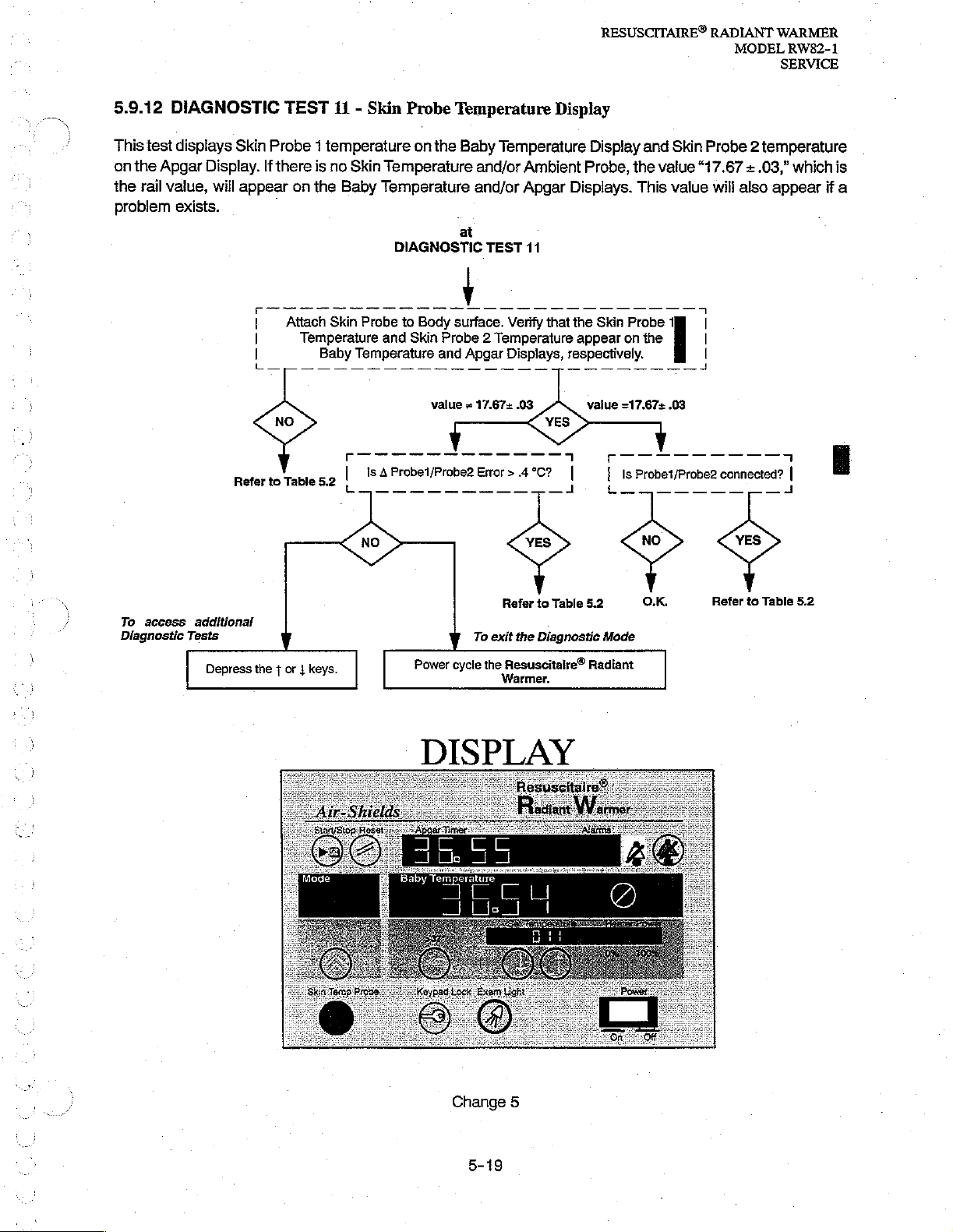
5.9.12
This
test
on
the
Apgar
the
rail
problem
DIAGNOSTIC
displays
value,
exists.
Skin
Display.
will
appear
TEST
11 - Skin
Probe 1 temperature
If
there
is
no
Skin
Temperature
on
the
Baby
Temperature
DIAGNOSTIC
Attach
Skin
Probe
Temperature
Baby
and
Temperature
Probe
Temperature
on
the
Baby
and/or
and/or
at
to
Body
surface.
Skin
Probe 2 Temperature
and
Apgar
Display
Temperature
Ambient
Apgar
TEST
11
Verify
that
Displays,
Display
Probe,
Displays.
the
appear
respectively.
Skin
and
the
This
Probe
on
the
Skin
Probe 2 temperature
value
“17.67 + .03,”
value
4
1
|
will
also
which
appear
is
if
a
To
access
Diagnostic
additional
Tests
Depress
th
the + or | keys.
keys.
Refer
to
Table
5.2
To
exit
the
Diagnostic
Power
cycle
the
Warmer.
OO
Resuscitalre®
Mode
paar
Radiant
Refer
to
Table
5.2
DISPLAY
À
Change
5
RESUSCITAIRE®
MODEL
SERVICE
RW82-1
RADIANT
WARMER
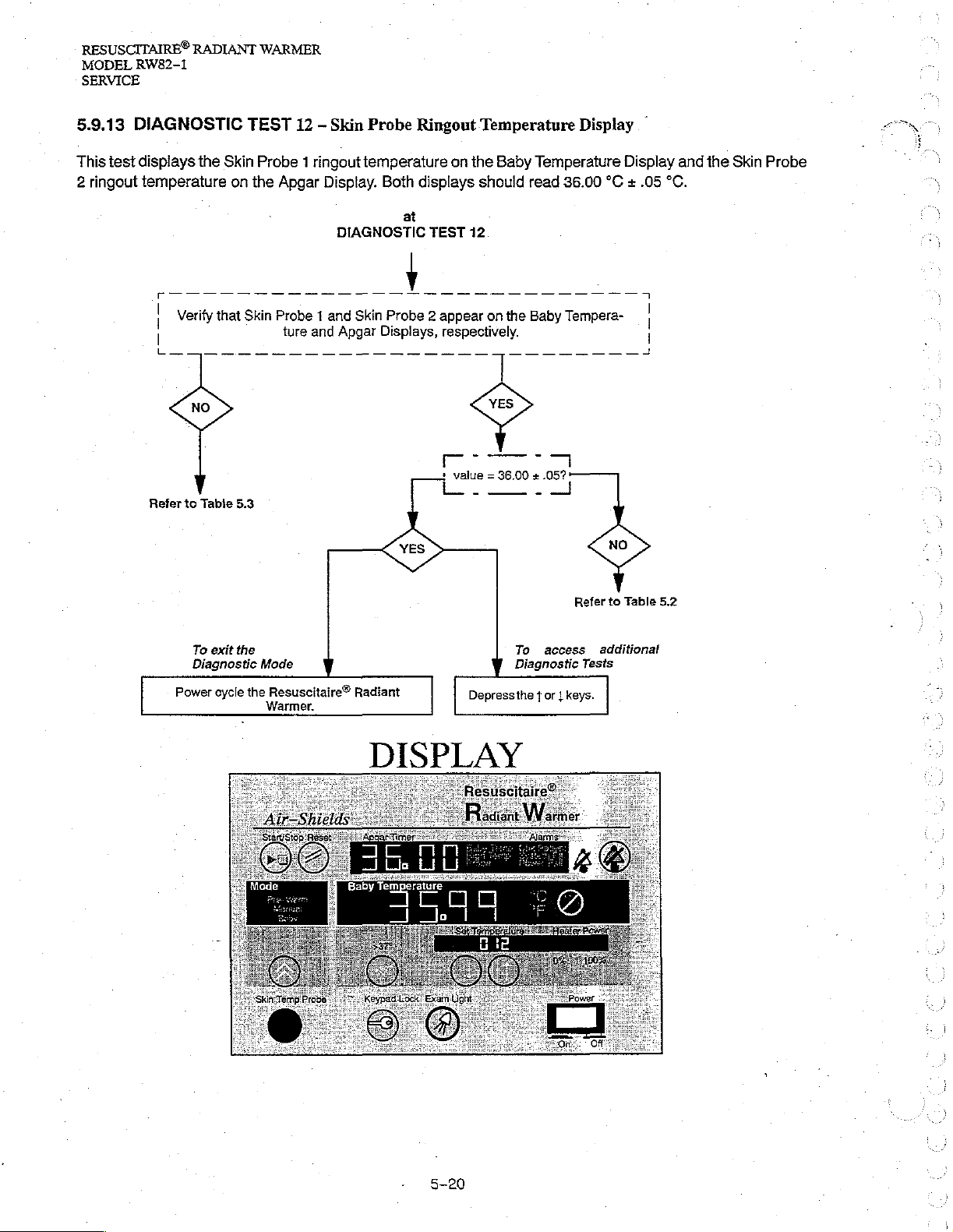
5.9.13
This
test
2
ringout
DIAGNOSTIC
displays
temperature
Refer
the
Verify
to
Table
TEST
Skin
Probe 1 ringout
on
the
Apgar
that
Skin
Probe 1 and
5.3
12 — Skin
Display.
ture
and
Probe
temperature
Both
at
DIAGNOSTIC
Skin
Probe 2 appear
Apgar
Displays,
Ringout
displays
TEST
Temperature
on
the
should
12
respectively.
+
value = 36.00 + .05?
tL
Baby
on
the
Display
Temperature
read
36.00
Baby
Tempera-
©
Display and
°C + .05
|
°C.
the
Skin
Probe
To
exit the
Diagnostic
Power
cycle
Mode
the
Resuscitaire“
Warmer.
Radiant
DISPLAY
Refer
To
access
Diagnostic
Depressthe $ or | keys.
Tests
to
Table
additional
5.2
5-20
 Loading...