

Air-Shields Mobile Infant Warmer User manual
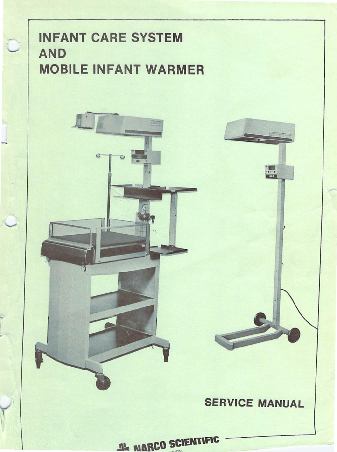
INFANT
AND
MOBILE
CARE
INFANT
SYSTEM
WARMER
SERVICE
ML
MARCO
SCIENTIFIC
MANUAL
The
product
reared
During
certified
no
charge,
This
resultant
This
described
dence
All
consumable
shipment
the
one
Air-Shietds
except
warranty
therefrom
1.
Damage
2.
The
customer
customer
The
3.
Air-Shields.
or
Sale
4.
warranty
We
NOTE:
Guardian
in
this
and
only.
year
is
to
service
is
suggest
Maintenance
disposable
warranty
dealer
labor
costs,
rendered
if:
the
unit
fails
uses
is
of
lieu
in
that
to
void
is
to
any
performed
all
insurance
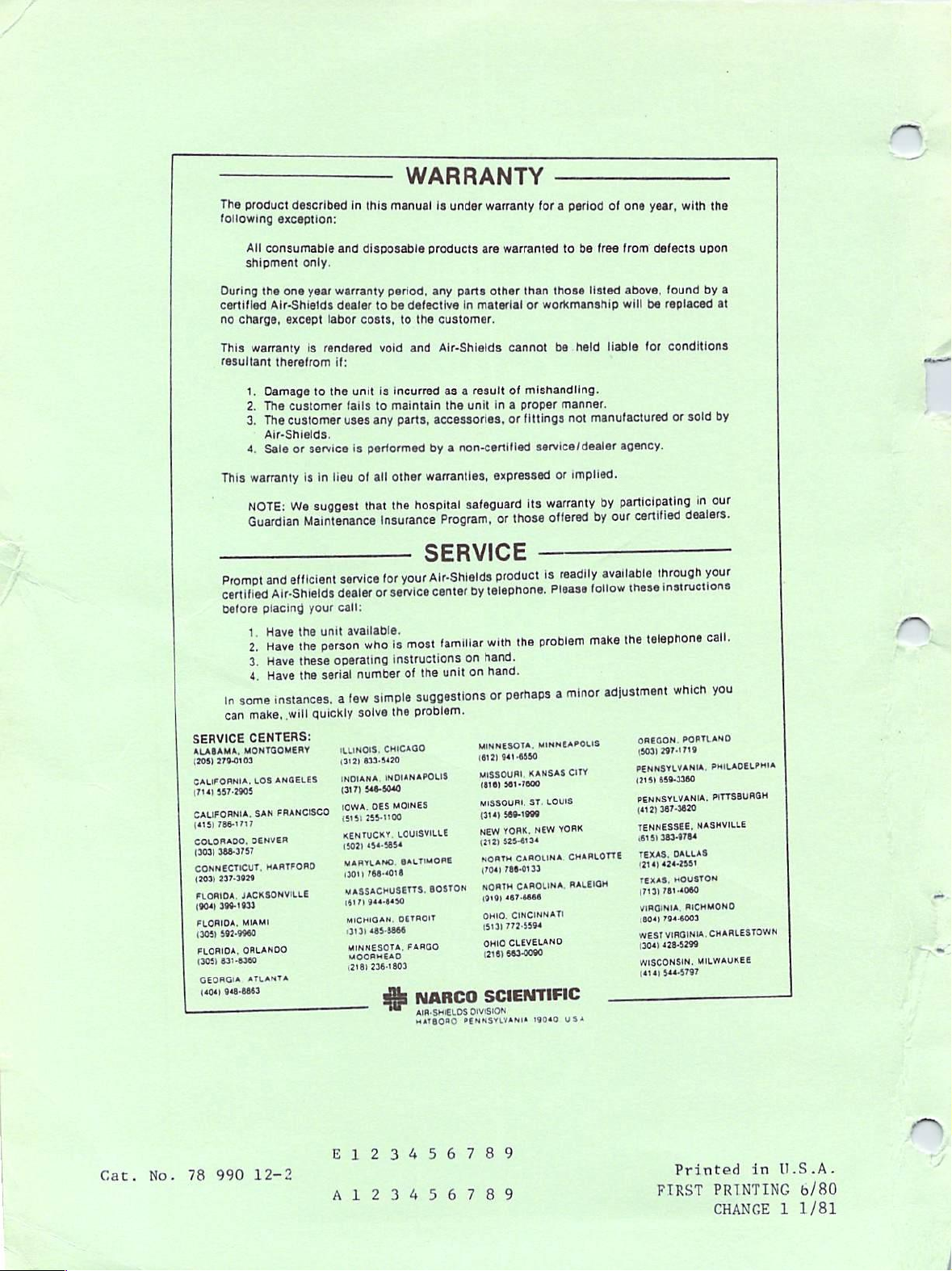
WARRANTY
manual
is
under
products
period,
any
be
defective
to
incurred
maintain
parts,
other
the
parts
the
customer.
and
Air-Shields
as a result
the
accessories,
non-certifled
a
by
warranties,
hospital
Program,
in
safeguard
warrant)
warranty
are
warranted
other
than
material
cannot
of
unit
in a proper
fittings
or
expressed
those
or
for a period
those
or
workmanship
be
mishandling.
service
or
warranty
its
offered
to
be
free
listed
held
manner.
manufactured
not
dealer
implied.
by
by
of
liable
our
one
from
above,
will
agency.
participating
certified
i
year,
with
defects
found
be
replaced
for
conditions
sold
or
dealers.
in
the
upon
by
a
at
by
our
Prompt
certified
before
SERVICE
ALABAMA,
279-0103
(208)
era
Fa
ο
placing
1.
Have
Have
2.
Have
3.
Have
4.
some
In
make,
can
CENTERS:
MONTGOMERY
a
Air-Shields
instances,
will
ο
efficient
and
e
qtroRD
A
E
SA
AS
JACKSONVILLE
FLORIDA,
CEAT
MIAMI
FLORIDA,
592-9960
(205)
ORLANDO
FLORIDA,
ECO
ATLANTA
GEORGIA
aras
Cai
service
dealer
your
call:
the
unit
available.
who
person
the
operating
these
the
ο
number
serial
few
a
solve
quickly
ILLINOIS,
633-5420,
(312)
δρ
sco
thr
10144.
arse
a
KENTUCKY,
5405854
[soar
MARYLAND.
koro
MASSACHUSETTS,
rao
sain
MICHIGAN.
1313)
MINNESOTA,
BESLE
(218)
or
simple
DES
485-8866
236-1909
SERVICE
Air-Shields
your
for
CHICAGO
center
service
familiar
most
is
instructions
the
unit
the
of
suggestions
problem.
πο
MOINES
ios
LOUISVILLE
SALTMORE
BOSTON
DETROIT
FARGO
NARCO
SÉ
AIR:SHIELOS
HATBORO
product
telephone.
by
with
hand.
on
hand.
on
or
MINNESOTA,
1612)
o
anion
ia)
MISSOURI,
öte
NEW
cara)
NORTH
NORTH
a
OM,
1513)
OHIO
me
SCIENTIFIC
DIVISION
PENNSYLVANIA
available
readily
is
follow
Please
problem
the
perhaps
MINNEAPOLIS
941-6550
ae
ST.
saptan
NE
YORK,
sesta
CAROLINA,
η
CAROLINA.
rae
CINCINNATI
772-5594
CLEVELAND
19040
make
adjustment
minor
a
O
LOUIS
YORK
CHARLOTTE.
RALEIGH
USA
your
through
instructions
these
telephone
the
OREGON,
1503)
ος
DCT
PENNSYLVANIA,
fura
TENNESSEE,
(615)
TOUS
Rates
i:
i
west
WISCONSIN,
scorsi
call.
you
which
PORTLAND
297-1719
367.620
3890754
Cet
ο
PITTSBURGH
NASHVILLE
DNS
ος.
ii
ina
CARL
MILWAUKEE
Cat.
No.
78
990
12-2
πο
A
ο
ο
27304567
ο
8
9
9)
Printed
FIRST
U.S.A.
in
PRINTING
CHANGE 1 1/81
6/80
PLEASE
READ
»
Please
of
Since
ment
incorporated
into
is
under
material
in
right.
check
this
manual.
Air-Shields,
program,
the
printed
provided
separate
on
the
margin
NOTE
Some
parts
which
occurs
not
in
appear
alter
the
because
Parts
for
circuit
into
on
separate
cover
each page
next
ON
used
the
in
in
the
of
function
List.
change
equipment
manuals.
information
Inc.
conducts a continuous
and
sheets
in
the
or
to
the
REPL.
your
equipment
Parts
difficulty
of
component
before
When
at
form
text
is
changed
List
in
the
of
equipment.
attached
improvements
they
can
this
occurs,
the
rear
of
of a change
indicated
material,
by a vertical
PARTS:
may
be
different
this
manual.
parts
procurement,
Order
to
the
product
are
be
incorporated
changed
the
manual
package.
as
shown
|
This
the
rear
improve-
sometimes
material
Changed
on
than
sometimes
but
does
part
cover
or
bar
the
those
listed
"
C
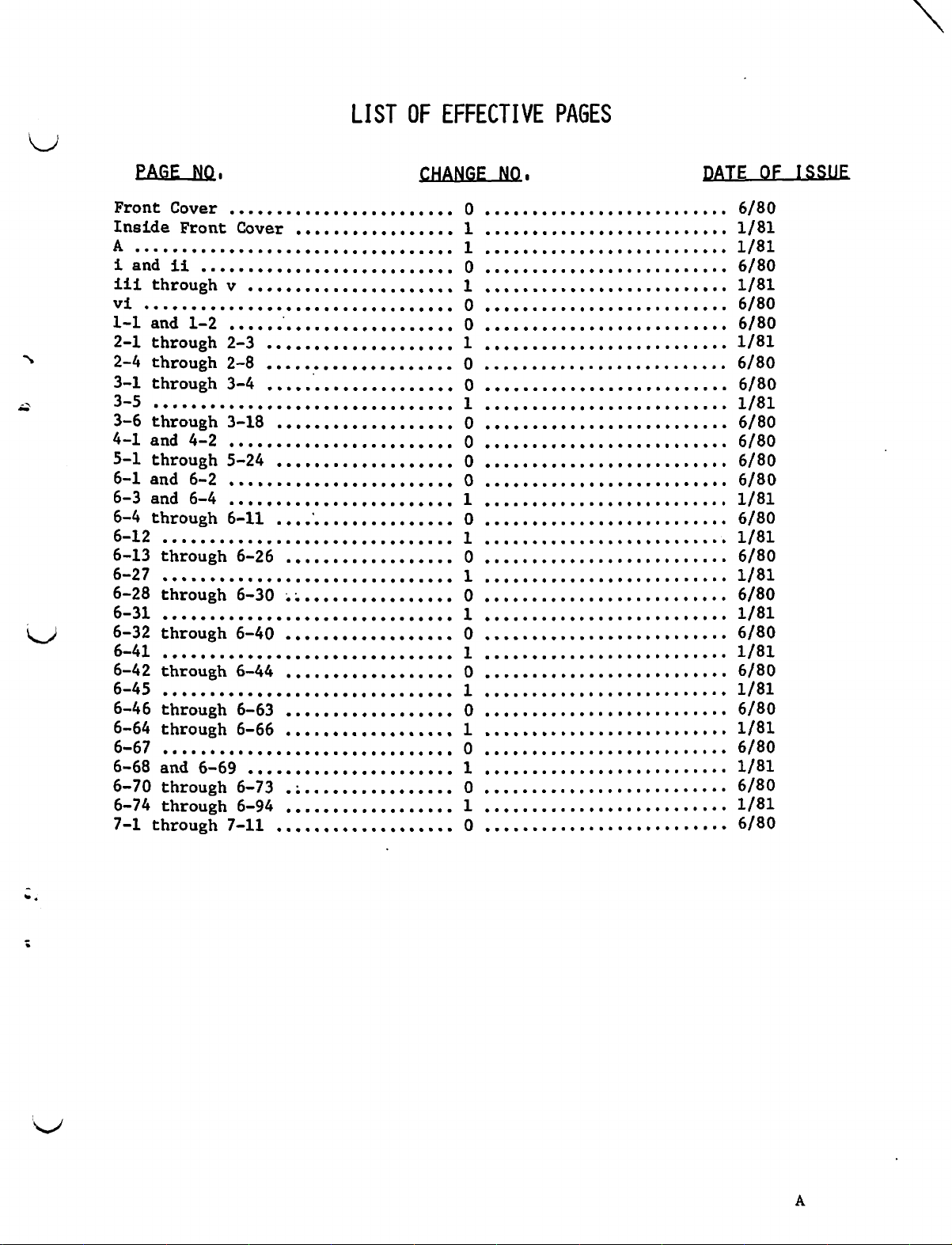
PAGE
NO,
LIST
OF
EFFECTIVE
CHANGE
NO.
PAGES
DATE
OF
ISSUE
b
Front
Inside
Ai
land
iii
through
VÍ
0...
1~1
and
2-1
through
2-4
through
3-1
through
a
3-6
through
4-1
and
5-1
through
6-1
and
6-3
and
6-4
through
6-12
6-13
6-27
6-28
6-31
6-32
6-41
6-42
>
6-46
6-64
6-67
6-68
6-70
6-74
7-1
through
Cover
Front Cover
di
.................4.00
through
..........ccccc<c.
through
............c.c..+....++*
,.....,,,..,......
....ooooocoooocomoooo.»»o
V
...ooooooomonomononoso
000000000
1-2
.oo
2-3
2-8
3-4
3-18
4-2
,...,.....,...........,.
5-24
6-2
...,,..,........,.......
6-4
..,..,...,......,........
6-11
6-26
0. 0 0 0 0000...
..............,.,.
..........,.........
,..,................
..,.................
,.,,,....,.........
..,................
.,...........,....
00.00.0000
6-30
...,..............
0000000.
................cc.c...c.000000s
through
6-40
..................
.oo..。
through
through
through
and
through
through
6-69
7-11
6-44
6-63
6-66
.,..,.............
........,.....,...
.......<<<<«444+++s
ΡΟ
eee
vere
...ooooonomooomom?o.»oso.
6-73
6-94
.:................
,....,............
,,,,,,,,,,,,,,,,,。。
の の の
ee
ο.
.6/80
PA
20000
0000000000000
αυ
ee
。。。。。
ororfroropororcI0Iro0o0ro0oororro
,vv
es
還
90000
OFOoOW4Oror
so。
.vv
on...
0000
0
...
1/81
80
1/81
80
0
6/80
1/81
80
0
80
0
80
1
0
0
1
συ
6/80
1
es . 6/80
1
0
1781
6/80
81
。6/80
1
TABLE
TCS
OF
CONTENTS
AND
MTW
y
SECTION
GENERAL
1.1
1.2
1.3
INSTALLATION
2.1
2.2
2.3
INFORMATION
Introduction
Description
Equipment
Installation
2.1.1
2.1.2
Cleaning
0
perational
2.
2
La Lo
2.
Lo
.
yn
2
2
2.
2.
2.
+3.
e
Warmer
Lo
Manual
Wo
La
Lo
SUN
Resuscitation
Lo
no
and
Infant
Mobile
TABLE
29070000.
Accessories
Procedure
Care
Infant
OF
200..
eos
ones
....oooooooonorcoroooccrrrmmssrrrr>?r?oo.
System
Warmer
.......................
Checkout
Standard
Intensive
Examination
Module
Controller
Servo
Servo
Controller
Controller
serene
Bassinet
Care
Bassinet
Light
.oo
and
(sc78-1)
(SC78-2)
Aspiration
CONTENTS
00500.
.......cccccccccccccccccecccevccces
....oooooonommorsrornssororoms..».
..............cc..s..0..“c.0.....s
.....ooooonoooporroromsommoorrosoo.
......oooooooooomoomoposmossconcos
®
0 0 0 0 で る る の 00
40...
0.0.0.
een
4000000000000
een
0040000
.0
etes
00.0
ea
oP
seere
.vv
0 0 5 0 を
0040660000
00
5 0 0
è
0590060000006
00
0 r
................+...0++.++*
............++++++++.++«
......
«σας
è» 0 0 0 8 0a
ve
0006
eee
...
ο
2-1
2-1
2-1
2-2
2-4
2-4
2-4
2-4
2-4
2-5
2-5
2-6
3.
TECHNICAL
3.1
3.2
PREVENTIVE
4.1
4.2
3
4.3
INFORMATION
Specifications
Theory
3.2.1
2
3
4
of
Operation
General
Warmer
Manual
Servo
5 | Servo
6.
Resuscitation/Aspiration
MAINTENANCE
General
Cleaning
4.2.1
4.2.2
Recommended
........
and
General
Sterilization
................
...........++..
OC
Module
Controller
Controller
Controller
Sterilization
Cleaning
Calibration
20.
o
DC
neces
............
LC
<=...
.....ccsccccrrcorarcesos
(5C78-1)
(SC78-2)
........00000000000
..........c...<<.<.<...+...ss
System
css.
........ 0 6.0
Schedule
を と ジテ と と と と と
.........
...........
.....
πο
concorrer
000000...
すす
すす
すす すす
すす
すす
000000.
Go
0 0
P.
002.00.
DA
sata
o a 4 0 é
ee
すす
すす
すす
すす
ミキ と と
rosas
contos
000000
........0000000000000
と ミ
ミニ
こと
osseuse
0.0...
ascende
0.0...
sr...
.........
nata
.....0..
すす
と
40
3-1
3-6
3-6
3-6
3-6
3-6
3-10
3-15
4-1
4-1
4-1
4-2
SERVICE
eno
5-1
5-1
5-1
5-1
5.1
5.2
General
Calibration
5.2.1
5.2.2
5.2.3
Test
Test
è @ è 6 è d
and
General
ed
os
6 0 0 0 0 0 0
Test
.,.....
.oo
Equipment
Point
and
BS
Procedures
Required
Adjustment
0D 4 50
....,.-.5
..........
059
00380
Locations
4000600
100
0000000000000
o...
002..
0
GP
2.0000...
.................
00900208:
a..
....
.........
ICS
TABLE
AND
OF
MIW
CONTENTS
SECTION
5.3
5.4
5.2.4
5.2.5
5.2.6
5.2.7
5.2.8
5.2.9
5.2.10
5.2.11
5.2.12
5.2.13
5.2.14
”Measuring
5.2.15°
5.2.16
5.2.17
.
hd
Un
.
2
fh
Un
e
12
un
N
Nh
.
.
La
D
Ur
43
rou
0
ON
Un
【
Me
ㆍ
o ο
U
epa
pa
Un
PTOS
+
ων
οἱ
Ee
.
Qu
.
Co
TABLE
Manual
Manual
Servo
Supply
Servo
Measuring
Servo
Circuit
©
Servo
Warm-Up
Servo
Angle
Servo
Servo
TestS
Servo
Frequency
Servo
Servo
Circuit
Servo
Control
Servo
Adjustment
O
Servo
ww
Resuscitation
Resuscitation
HO
Aspiration
Venturi
eshooting
FN
General
Test
r
and
General
Controllers
Venturi
Controller
Controller
Controller
Controller
Controller
Control
Controller
Controller
Controller
Controller
Controller
Controller
Controller
Controller
Equipment
Replacement
CONTENTS
OF
Controller
Controller
(CONTINUED)
Calibration
Leakage
(SC78-2)
..ooooooooopooroosorsrcncraronsrrsssn.»
TestS
+.
(SC78-1)
ο
Adjustment
ο
(SC78-1)
Calibration
L...00.000000
(SC78-1)
Lo-Alarm
Disable
(SC78-1)
Adjustment
(SC78-1)
(SC78-2)
+..ooooooo.o..
ュー
(SC78-2)
Test
............
(SC78-2)
Circuit
..
.vv..。
(SC78-2)
Calibration
.........
(SC78-2)
Adjustment
..,.........ssssesseseessosessssse
(SC78-2)
.........c.<<.+.*
(SC78-2)
System
System
with
without
System
ASpirator
........
........:,,.....
.......-..00000
人
Required
aaaoaoaoaoaosoosoeososeeseesssasessssese
Procedures
.vv
...........
Resuscitation/Aspiration
servrresreeorio
..........
Test
..........s.eseossese
Power
Temperature
Alarm
Initial
Test
.........++++++++++4+««
Phase
........
Leakage
Power
Supply
ee
Clock
PPE
Temperature
Alarm
s.s.s.
Phase
Alarm
Angle
Delay
Leakage
Tanks
.....,,........,....,.
Tanks
.........
soosossvsrsss
ο
000000000000
eee
ee
Test
..........+...
κ
Test
............«..
.................,
00000000000
000000000
cororsorronosrrrr.
ser
eric
ere
System
.............
κ.
ser
00
PAGE
52
572
5-2
5-4
DIG
5-5
İZİ
5-7
37
5-9
3-10
0
9-1
5-11
5-12
5713
5713
人
5-14
3-20
3720
9720
5-22
ii
PARTS
6.1
General
DIAGRAMS
7.1
General
LIST
............
....................
c.:
...
00...
7-1
TABLE
ICS
OF
CONTENTS
AND
N
MIW
LIST
OF
ILLUSTRATIONS
ILILE
Typical
Assembling
Installation
Assembling
Typical
Typical
Test
Servo
Controller
Test
5
Servo
PCB
Micro-Filter
Venturi
Infant
Covered
Manual
PCB
Servo
PCB
Diagram
PCB
Diagram
Servo
PCB
Diagram
PCB
Diagram
Standard
Diagram
Intensive
Intensive
Location
Mobile
Warmer
Intensive
Parts
Intensive
Parts
m
6.18
Resuscitation/Aspiration
Diagram
Venturi
Parts
6.19
6.20
Oxygen
Location
Oxygen
Parts
Infant
Resuscitation/Aspiration
Aspiration
Point
Controller
Point
Controller
Assembly
Removal
Care
in
Controller,
1,
Manual
Controller
1A,
Servo
........ о ь
2A,
Servo
.............++....“...0..00000000000040000000000400
Controller
1A,
Servo
.vv
2A,
Servo
Care
the
Infant
of
the
Mobile
and
Adjustment
Phase
and
Adjustment
Location
Removal
System
this
Section
Controller,
Controller
Controller
Controller
Controller
System
Care
Retaining
Infant
EK
System
Knob
Warmer
.....
esse...
.....ccccscccccccccccccccece
System
System
(SC78-1)
Conduction
(SC78-2)
............0...+..+.+......““.......“..00006
.vv
and
Parts
Model
оо
ооо
(SC78-2),
.......cccccecccccccccccecccccccececes
Locations
....
Locations
.........
Diagram
Mobile
..........
Location
Parts
SC78-1,
(SC78-1),
овово
(SC78-1),
Parts
(SC78-2),
(SC78-2),
ccc
Angle
................ccc+w.444«
Infant
Parts
PCB
cece
cc
..................
PCB
-0000000
Warmer
serer...
Diagram
Location
Location
Parts
ооо
новое
розовое
Parts
Location
Parts
Parts
.oo
Cart/Bassinet
........
Care
Cart
Care
Basic
Diagram
Infant
Module,
Care
Location
Care
Location
......
........00100
Warmer,
Parts
Bassinet
DiagraM
Bassinet
Diagram
0000000000000
Resuscitation/Aspiration
Location
Delivery
Diagram
Delivery
Location
Diagram
System
......oooooooooo»oooo».
System
DiagraM
Assembly,
すす
すす
すす
Assembly,
Weld
Cart
Parts
Location
(Part
たと
Parts
を
Parts
Assembly,
00000000
Location
DiagraM
No.
Location
と
とも
Location
00000000
Diagram
........».ooooooroonono»oso
78
140
.....oooooooooonoronocasonconranonornos
(Part
No.
78
140
.............«+..
Assembly
00000
Parts
た と すす
Assembly,
......ooooooooooroomoscsoncoroosonsso
with Tank
without
......ooooooo....
Provision
Tank
Provision
v.s.
a
as
sas
sas
sro
hd
dd
L
O"
cada
escocesa
............<<..c<<«cc««4
2A
ces
cccscecccecccnccucee
s.a.
2A
000..
...............
Diagram
...
Equipment
...............
Diagram
と
と
すす
..
.......
........
すす
000...
Location
ово
ово
ввоза
ооо
Location
0000006
Diagram
.............
Location
Location
……9
も も も も
Diagram
Parts
cc
nanrcoconioreone
...........+++.++.++.
70),
.....
"σα
と と ここ
sono.
71),
oo。
Location
を を
です
たと
と と ここ
Parts
s.s.s...
こと
s.s...
......
sus...
coo.
‘e.
すす
すす
ae
ro
....
..
.
.
.
.
6-60
(Change
1)
iii
IcS
TABLE
AND
MIW
OF
CONTENTS
6.21
6.22
6.23
6.24
6.25
6.26
6.27
6.28
6.29
+
Fu
ο
SO
ty
0.
SE
lo
E
.
SES
SE
la
.
JQ
0
“AEA
Examination
Location
Examination
Location
Monitor
Location
Monitor
Basic
Gas
(One
Gas
(Two
AC
Receptacle
Instrument
Bassinets),
Instrument
Care
o
I.V.
Functional
Functional
Functional
Schematic
Schematic
Schematic
Wiring
Schematic
LIST
Light
Diagram
Light
Diagram
Shelf
Diagram
Shelf
Weld
Cart
Delivery
Piece
Delivery
Piece
Bassinets),
Pole
Hose
Hose
Tray
Tray
Assembly,
Block
Block
Block
Diagram,
Diagram,
Diagram,
Diagram,
Diagram,
OF
.......
......
Assembly
(Standard
Assembly
Parts
Panel,
Assemblies)
Panel,
Assemblies)
Box,
(For
Parts
(For
Parts
Diagram,
Diagram,
Diagram,
Servo
ILLUSTRATIONS
TITLE
(Flexible
(with
Location
Parts
Parts
Parts
Use
Location
Use
Parts
Manual
Servo
Servo
Controller
Warmer
Extension),
e
Ore
Rigid
2.00...
(Single
and
(Single
Location
.......0.%.
Location
.........+.+.+.+.+.++*
Location
with
Diagram
with
Location
Location
Manual
Servo
Servo
Controller
Controller
Controller
Module
e
Extension),
0.00..
or
Intensive
or
Diagram
Standard
Intensive
Diagram
Controller
Controller
Controller
(CONTINUED)
Parts
rca
oo
Oss
o
as
Parts
.............
Double
Double
Diagram
Diagram
Diagram
...........+..++..
Diagram
(SC78-2)
..........
Tier),
Care
Carts)
Tier)
.....o.ooooooooonoonnonaso
すす
すす
すす
..........
...........
.....ccccesccccccecer
.,......,,.......s...
(SC78-1)
(SC78-2)
................
(SC78-1)
(SC78-2)
..............+.++.
...........
.................
00010000000
0000000000000
ron
-0.0
0...
Parts
...........
すす
すす
すす
すす
すす と すす
coooooooo...
sons.
PA
............
.......
0000000000
.......
すす で で と と
テテ
.....
PE
て
600.050
.....
で
6-70
6-72
6-74
6-76
6-78
6-82
6-86
6-88
6-90
6-92
7-3
7-5
7-6
7-7
7-9
7-10
7-11
(Change
1)
Iv

TABLE
ICS
OF
CONTNETS
AND
MIW
E
U
o
いひ
いひ
の
いい
の
ひひ
の
ひひ
の
いい
の
の
ひい
いい
ひひ
の
いひ
の
ひい
の
.
9
o
e
. e
Specifications
ps
Infant
po
Equipment
Manual
PCB
Servo
Bb
PCB1A,
U
PCB2A,
VNO
Servo
PCBIA,
PCB2A,
MOO
Standard
RH
No
Intensive
Parts
Mobile
Warmer
E
Intensive
Intensive
Resuscitation/Aspiration
OVA
Venturi
Oxygen
Oxygen
Examination
Examination
LINHO
Monitor
NNNNEPEHPEHHHHE
Parts
Monitor
Parts
Gas
Hose
Gas
Hose
AC
Instrument
Instrument
Parts
I.V.
.vv
Care
Controller,
1
for
Manual
Controller
Servo
Servo
Controller
Servo
Servo
Cart
Care
List
Infant
Module,
Care
Care
System
Covered
Controller
Controller
Controller
Controller
...........«.........s.«s
and
in
Parts
Controller,
Model
(SC78-2),
Assembly,
Bassinet
Warmer,
Parts
Bassinet,
Bassinet,
Resuscitation/Aspiration
Delivery
Delivery
Shelf
List,
Shelf
List,
Delivery
Assemblies)
Delivery
Assemblies)
Receptacle
List
and
Tree
Light
Light
Assembly
Standard
Assembly
Basic
Panel,
Panel,
Box,
Tray
Tray
μμ
Pole
System
System
(Flexible
(With
Weld
Parts
.oo
Parts
...,.........:
Parts
(For
(For
Assembly,
LIST
TITLE
Mobile
this
List
(SC78-1),
(SC78-1),
(SC78-1),
(SC78-2),
(SC78-2),
Parts
Basic
Parts
List
Parts
Parts
Assembly,
With
Without
Rigid
(Single
and
(Single
Cart
List
Use
With
Use
With
ο
OF
TABLES
Infant
Section
.................
Parts
Parts
List
Weld
List
....,.....ssesssssosssseusess
List
List
Tank
Tank
Extension),
Extension),
or
Intensive
or
......
List
List
(One
(Two
Warmer
.....ccecccccsccevccecceveees
v.s...
List
Parts
Parts
Parts
List
Parts
Parts
Cart
.....oooooooooooooooo.o.
Parts
Assembly,
Provision,
Double
Double
..................,....。
List
....................
LiSt
List
...ooooooooo
...oooooooooooooor.o.
............++..+++.
List
List
.............
Assembly,
すす
(Part
(Part
Provision,
Parts
............
...........sssssues
チチ
すす
ササ
で と
すす
No.
78
140
No.
78
140
List
............
Parts
Parts
Parts
List
Parts
List
List
List
Tier),
Care
Carts
....+.++++.+++.««.«
Tier)
νο
ος ος
«ος
č...
Piece
Piece
.ov
.....oo.o.o»....
Standard
Intensive
ο
ο
Parts
List
coronan
Bassinet),
Care
Bassinets),
sarro
ο
..........«««+++++.++.+..«..
ooo...
como...
cu.
ナド
すす
すす
s.s.s...
sese
>
70)
.......
71)
.......
..........
.........
List
...........
...........
s.s...
ere
rese
nonoor.s.
Parts
se
List
senna
すす
すす
の
coo...
......
..
rese
...
da
。
ın
(Change
1)
V
IcS
TABLE
AND
MIW
OF
CONTENTS
Manual
Servo
Servo
Controller
Controller
Controller
LIST
OF
FLOWCHARTS
TITLE
Troubleshooting
(SC78-1)
(SC78-2)
Troubleshooting
Troubleshooting
.......
Roses
........++.+.+.+«+«+««
sn
ue,
.......+++.++++++e+++«
PAGE
5-15
5-16
5-18
у
vi
m
GENERAL
ICS
AND
MIW
INFORMATION
SECTION
GENERAL
1,1
This
troubleshooting,
Air-Shields®
It
do
instructions
in
indicated
This
the
1.2
The
that
term
aspiration,
INTRODUCTION
manual
is
the
Section
manual
unit.
provides
Mobile
responsibility
in
5
of
must
should
DESCRIPTION
Air-Shields®
may
be
used
treatment
and
instructions
and
repair
Infant
this
manual,
this
manual
be
performed
be
Infant
immediately
of
infants
when
other
of
read
Care
of
the
Warmer.
the
and
are
only
thoroughly
System
after
requiring
special
INFORMATION
for
Air-Shields®
user
to
to
ensure
performed.
by
Air-Shields
is
birth,
access,
needs
1
installation,
Infant
operate
by
all
designed
during
are
the
that
the
Maintenance
certified
personnel
to
visability,
required.
use,
unit
maintenance
provide
special
operator
Care
System
in
accordance
requirements
service
who
will
an
integrated
procedures,
thermal
maintenance,
and
the
with
recommendations
so
representatives.
be
working
or
support
with
system
for
long
and/or
the
The
Air-Shields©
readily
The
Warmer
Infant
Controller
1.5
m
Since
factured
relating
representative.
moved
Infant
Care
Module,
Warmer
Module.
EQUIPMENT
manual
this
systems
to
Mobile
and
used
System
and
either a Manual
consists
PROVIDED
provides
as
equipment
typical
A
Infant
with
consists
of
well
provided
Warmer
bassinets
of a Cart/Bassinet,
the
Warmer
AND
maintenance
equipment
as
and
Infant
is
designed
currently
or
Servo
Module
in
Controller
and
the
ACCESSORIES
parts
and
longer
no
accessories
System
Care
manufactured,
should
is
to
provide warmth
use
in
oxygen
Module.
Manual
information
directed
be
shown
in
the
nursery.
delivery
or
Servo
for
all
Figure
and
system,
The
Mobile
‘
currently
questions
your
to
1.1.
to
be
manu-
sales
Ics
AND
GENERAL
MIW
INFORMATION
BASSINET
MODEL
EXAMINATION
LIGHT
INTENSIVE
BASSINET
NUMBER
IV,
CARE
POLE
WARMER
SERVO
CONTROLLER
CONTROLLER
MODEL
SERIAL
OXYGEN
SYSTEM
OXYGEN
MOUNTED
REAR
MODULE
AND
NUMBER
ODEL
ERIAL
OF
ANO
NUMBER
DELIVERY
TANKS
ON
CART
リリ
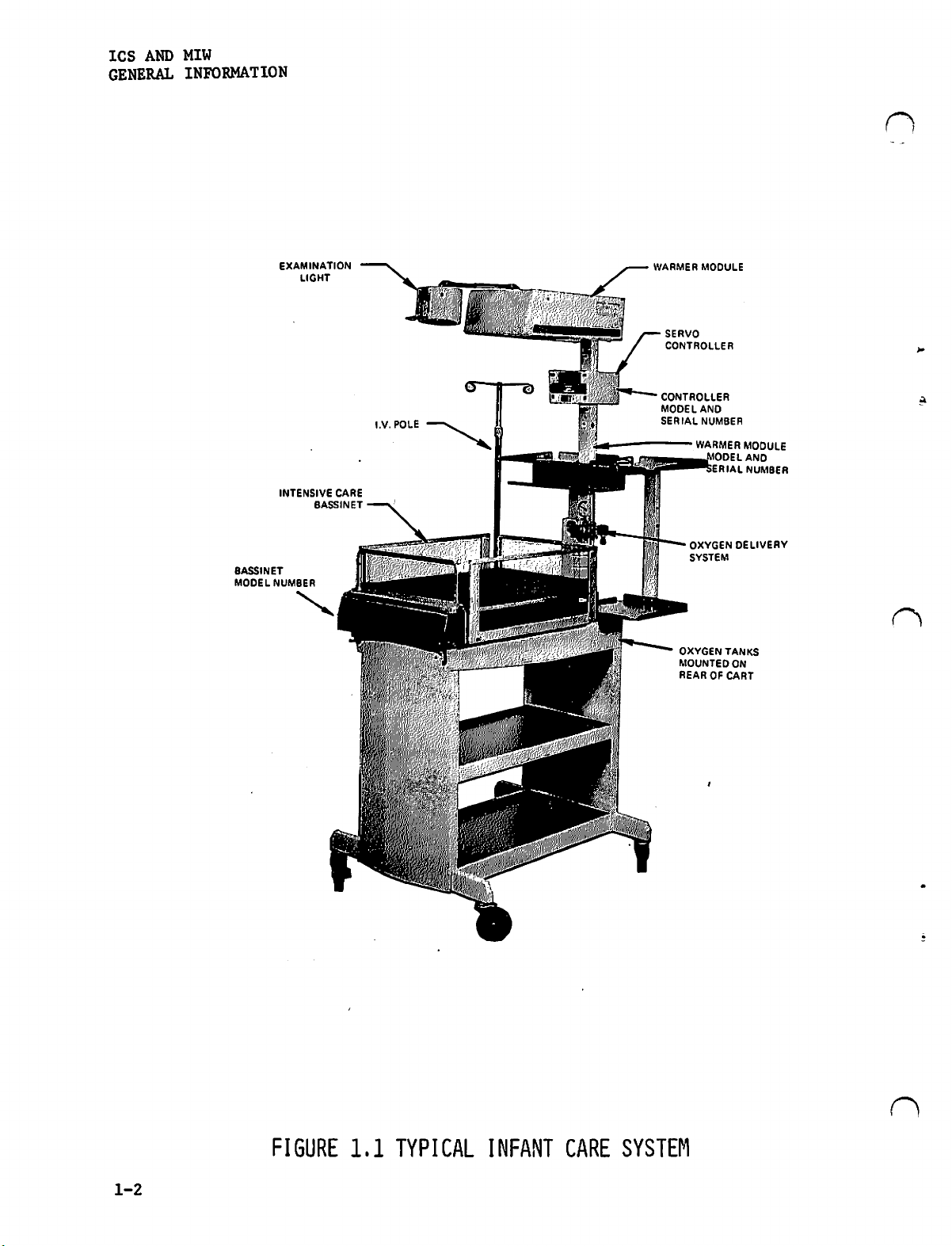
FIGURE
1.1
TYPICAL
INFANT
CARE
SYSTEM
ICS
AND MIW
INSTALLATION
すり
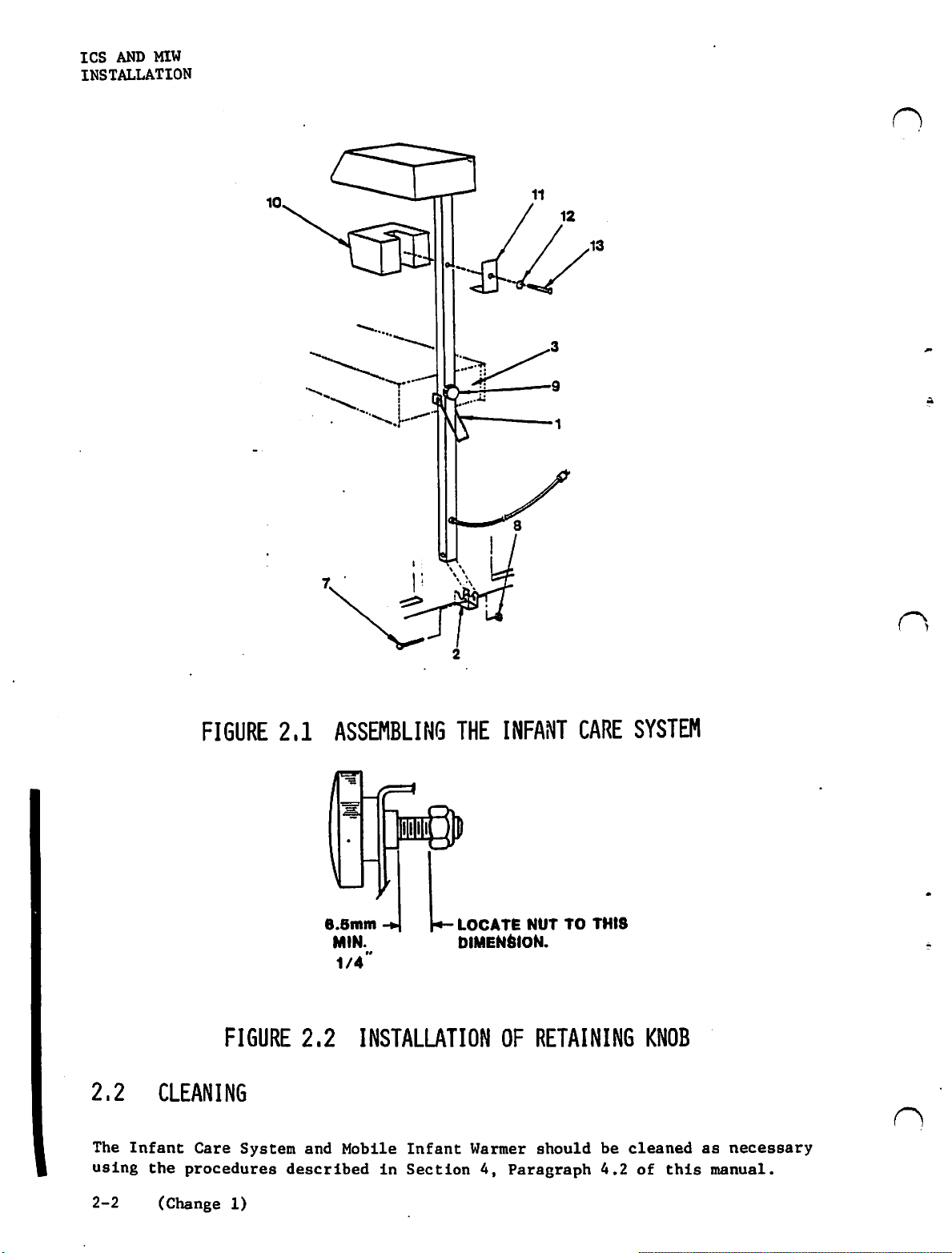
2.1
2.1.1
A.
The
Cart/Bassinet,
Assembly
Refer
(1),
Position
the
Assembly
Secure
Tilt
Plug
then
INSTALLATION
INFANT
Infant
then
Base
Knob
the
secure
Care
will
to
Figure
slide
the
Assembly.
with
the
Warmer
(6).
controller
it
bottom
PROCEDURE
CARE
Warmer
require
the
using
SYSTEM
System
2.1
and
the
Warmer
of
Secure
2-1/2"
Module
(7)
is
Module
no
the
the
SECTION
INSTALLATION
shipped
special
slide
Module
Warmer
the
long
Post
into
Bracket
broken
Post,
tools.
the
line
Post
Module
bottom
bolt
to
the
the
receptacle
(8),
and
and
Cart/Bassinet
2
down
Manual
cord
through
Post
of
the
"KEPS"
screw
to
or
through
the
over
Warmer
nut
on
the
(10),
four
assemblies.
Servo
the
Arm
the
Module
(4
and
Assembly,
Warmer
washer
and
Controller.
Arm
Catch
Catch
Assembly.
projection
Post
5).
using
Module
(9).
The
Assembly
(2)
to
the
the
Post,
on
Base
Before
Retaining
is:
Remove
Retaining
until
Install
Place
the
center
Cart.
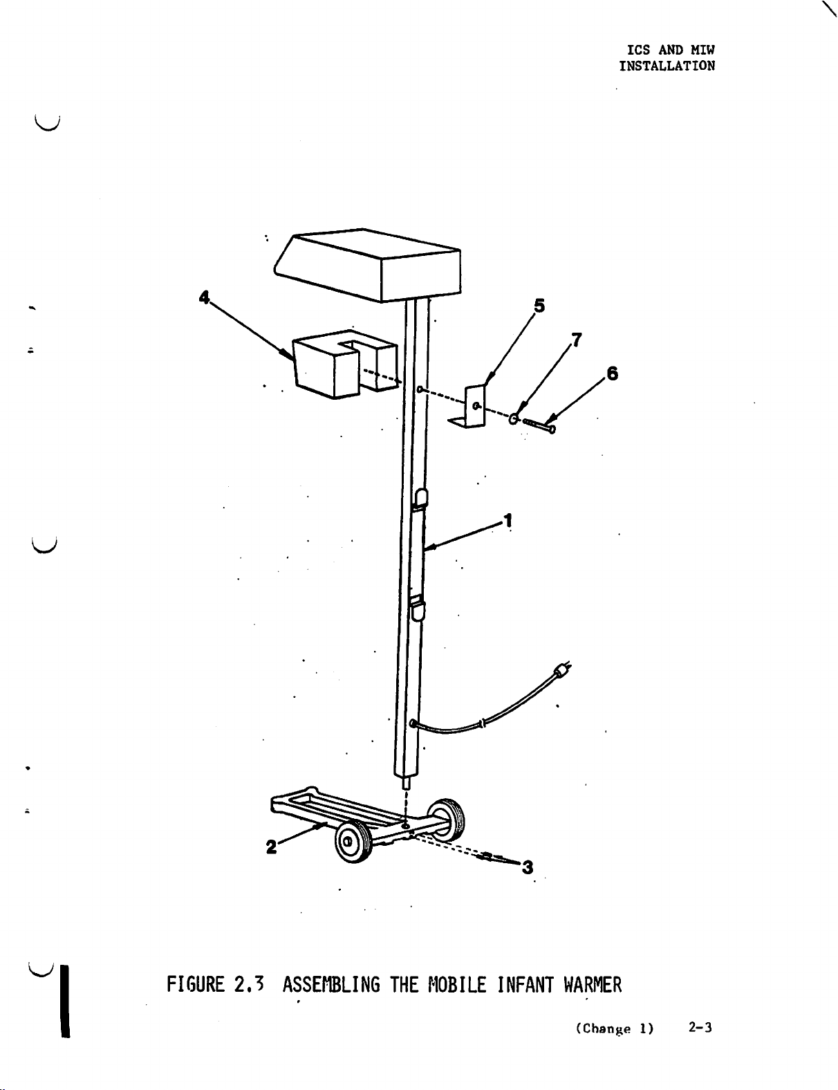
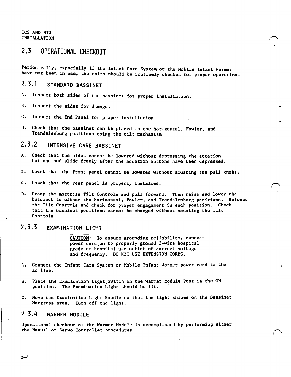
2.1.2
м
A.
The
Base
will
Refer
Assembly
the
the
Knob must
contained
the
Knob
the
knob
the
the
Adjustment
Cart
Adjustment
of
each side
MOBILE
Mobile
Assembly,
require
to
Figure
(2).
two
allen
Bassinet
in a plastic
Bassinet
into
is
contacting
locknut
INFANT
Infant
Warmer
no
special
2.2
Secure
screws
Warmer
is
placed
be
installed
bag
and
Retaining
the
hole
provided
Control
Bracket.
of
the
WARMER
is
Module
tools.
and
Mount
the
Warmer Module
(3).
on
the
on
in
the
Knob
located
the
panel.
on
the
of
the
Grasp
Bassinet,
shipped
Post,
the
Warmer
Infant
the
Bassinet.
Bassinet
from
on
the
Retaining
Bassinet
the
Release
pull
broken
and
Manual
Module
Post
Care
shipping
the
carton.
center
Knob
in
the
Mechanisms
outward,
down
to
or
Pose
to
the
System,
The
of
rear
as
illustrated
center
and
three
Servo
(1)
Base
the
Rear
Retaining
carton.
Screw
lower
assemblies.
Controller.
on
Assembly
of
the
slot
under
it
the
the
Panel
Knob
black
Bassinet
in
of
the
on
the
Assembly
Base
using
Figure
The
2.2.
Plug
secure
the
controller
it
using
the
(4)
into
Bracket
the
(6),
receptacle
screw
(6),
on
and
the
Warmer
washer
Module
(7).
(Change
Pose,
1)
then
2-1
ICS
AND
MIW
INSTALLATION
6.5mm
MIN.
1/4
=
te)!
Li
|
DIMENSION.
NUT
TO
THIS
2.2
The
Infant
using
2-2
FIGURE
CLEANING
Care
System
the
procedures
(Change
1)
2,2
and
Mobile
described
INSTALLATION
Infant
in
Section
OF
Warmer
4,
Paragraph
RETAINING
should
be
4.2
KNOB
cleaned
of
this
|
as
necessary
manual.
ICS
AND
MIW
INSTALLATION
|
FIGURE
2.3
ASSEMBLING
THE
MOBILE
INFANT
WARMER
(Change
1)
2-3
IcS
AND
MIW
INSTALLATION
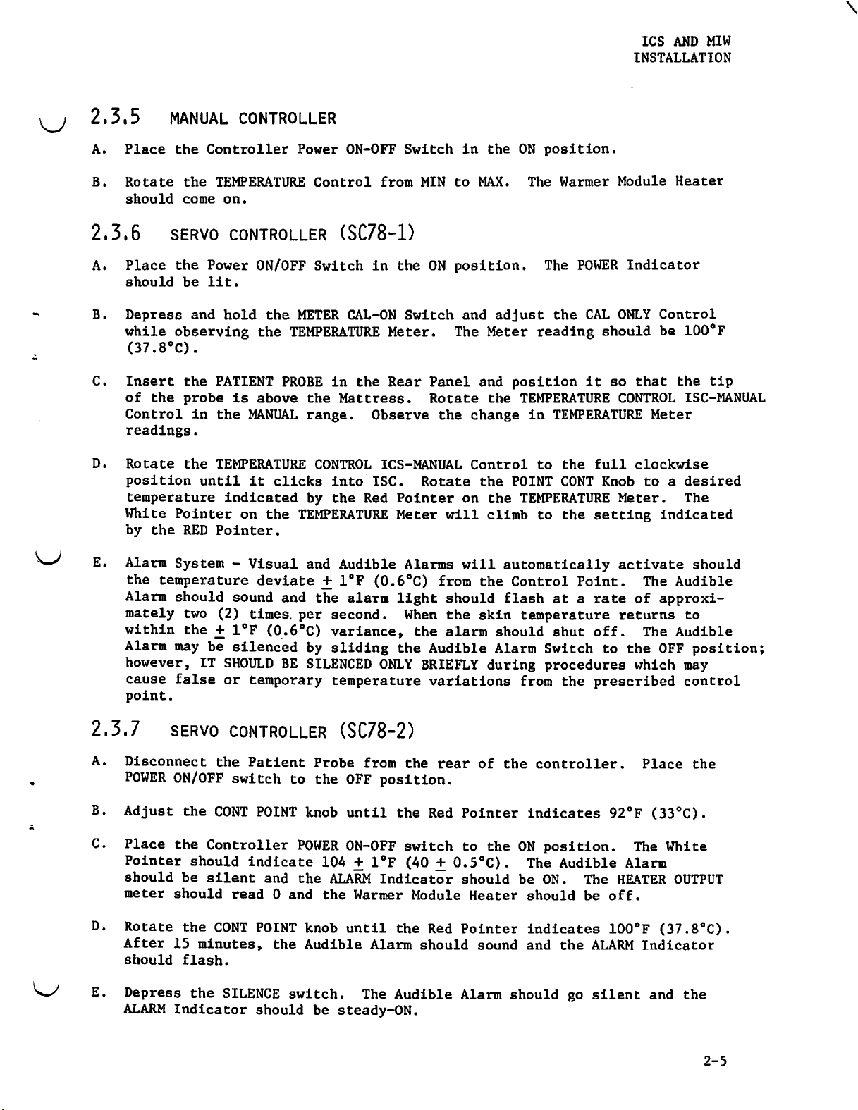
2,5
Periodically,
have
OPERATIONAL
not
been
2.3.1
A.
Inspect
B.
Inspect
C.
Inspect
D.
Check
Trendelenburg
2.5.2
A.
Check
buttons
B.
Check
C.
Check
especially
in
use,
STANDARD
both
sides
the
sides
the
End
Panel
that
the
bassinet
positions
INTENSIVE
that
the
sides
and
slide
that
the
front
that
the
rear
CHECKOUT
if
the
the
units
BASSINET
of
the
bassinet
for
damage.
for
proper
can
using
CARE
freely
BASSINET
cannot
after
panel
panel
is
Infant
should
be
placed
the
be
lowered
the
cannot
properly
Care
System
be
routinely
for
proper
installation.
in
the
tilt
mechanism.
without
acuation
be
lowered
installed.
or
the
checked
installation.
horizontal,
depressing
buttons
without
have
Mobile
for
Fowler,
the
been
acuating
Infant
proper
and
acuation
depressed.
the
Warmer
operation.
pull
knobs.
D.
Grasp
bassinet
the
that
Controls.
2.3.3
A.
Connect
ac
line.
B.
Place
position.
C.
Move
Mattress
2.3.4
Operational
the
Manual
the
mattress
to
either
Tilt
Controls
the
bassinet
-
EXAMINATION
CAUTION:
power
grade
and
the
Infant
the
Examination
The
the
Examination
area.
WARMER
checkout
or
MODULE
Servo
Tilt
the
horizontal,
and
check
positions
LIGHT
cord
or
hospital
frequency.
Care
Light
Examination
Light
Turn
off
of
the
Controller
Controls
for
cannot
To
ensure
on
to
DO
System
Switch
Light
Handle
the
light.
Warmer
procedures.
and
Fowler,
proper
be
grounding
properly
use
outlet
NOT
or
Mobile
on
should
so
Module
pull
forward.
and
engagement
changed
ground
of
USE
EXTENSION
Infant
the
Warmer
be
lit.
that
the
is
accomplished
Then
Trendelenburg
in
each
without
reliability,
3-wire
correct
CORDS.
Warmer
Module
light
shines
raise
position.
acuating
connect
hospital
voltage
power
Post
'
on
by
performing
and
lower
positions.
the
Tilt
cord
to
in
the
ON
the
Bassinet
either
the
Release
Check
the
2-4
ICS
AND
MIW
INSTALLATION
2.3.5
Place
A.
Rotate
B.
should
2,3,6
Place
A.
should
Depress
while
(37.8°C).
Insert
of
Control
readings.
Rotate
position
temperature
White
by
MANUAL
the
the
come
SERVO
the
be
observing
the
the
probe
the
Pointer
the
RED
CONTROLLER
Controller
TEMPERATURE
on.
CONTROLLER
Power
lit.
and
hold
PATIENT
is
in
the
MANUAL
TEMPERATURE
until
it
indicated
on
Pointer.
ON/OFF
the
the
TEMPERATURE
PROBE
above
clicks
the
Power
ON-OFF
Control
(SC78-1)
Switch
METER
TEMPERATURE
CAL-ON Switch
in
the
Mattress.
range.
CONTROL
into
by
the
the
Switch
from
in
the
Meter.
Rear
Observe
ICS-MANUAL
ISC.
Red
Pointer
Meter
MIN
to
ON
position.
The
Panel
Rotate
the
Rotate
will
in
the
MAX.
and
Meter
and
the
change
Control
the
on
the
climb
ON
The
adjust
reading
position
TEMPERATURE
in
to
POINT
TEMPERATURE
to
position.
Warmer
The
POWER
the
CAL
should
it so
TEMPERATURE
the
full
CONT
Knob
the
setting
Module Heater
Indicator
ONLY
Control
be
100°F
that
the tip
CONTROL
ISC-MANUAL
Meter
clockwise
to a desired
Meter.
The
indicated
Alarm
the
Alarm
mately
within
Alarm
however,
cause
point.
2.5.7
A.
Disconnect
POWER
Adjust
Place
Pointer
should
meter
Rotate
After
should
System - Visual
temperature
should
two
sound
(2)
times.
the + 1°F
may
be
silenced
IT
SHOULD
false
SERVO
ON/OFF
the
should
15
the
Controller
should
be
silent
the
CONT
minutes,
flash.
or
temporary
CONTROLLER
the
Patient
switch
CONT
indicate
read 0 and
POINT
and
Audible
deviate + 1°F
and
the
alarm
per
second.
(0.6°C)
BE
variance,
by
sliding
SILENCED
temperature
(SC78-2)
Probe
to
the
OFF
POINT
and
the
knob
POWER
104
the
ALARM
the
knob
Audible
until
ON-OFF
+
Warmer
until
Alarms
(0.6°C)
light
When
the
ONLY
from
the
position.
the
switch
1°F
(40
Indicator
the
Alarm
from
should
the
the
alarm
Audible
BRIEFLY
variations
rear
Red
+
0.5°C).
Module
Red
should
will
automatically
the
flash
skin
should
Alarm
during
of
the
Pointer
to
the
should
Heater
Pointer
sound
Control
at a rate
temperature
shut
Switch
procedures
from
the
controller.
indicates
ON
position.
The
Audible
be
ON.
should
indicates
and
the
activate
Point.
returns
off.
to
the
prescribed
92°F
Alarm
The
HEATER
be
off.
100°F
ALARM
The
Audible
of
approxi-
The
Audible
OFF
which
Place
(33°C).
The
White
OUTPUT
(37.8°C).
Indicator
should
to
position;
may
control
the
Depress
ALARM
the
SILENCE
Indicator
should
switch.
be
The
Audible
steady-ON.
Alarm
should
go
silent
and
the
2-5
ICS
AND
MIW
INSTALLATION
F.
Rotate
White
meter
G.
Rotate
sounds.
the
White
Module
H.
Depress
ALARM
the
CONT
Pointer.
should
the
CONT
The
Pointer.
Heater
the
SILENCE
Indicator
read
Red
should
POINT
The
ALARM
1/2
POINT
Pointer
The
switch.
should
knob
or
knob
be
be
until
Indicator
greater
slowly
should
HEATER
OFF.
The
steady-ON.
the
Red
Pointer
should
and
the
Warmer
counterclockwise
indicate
OUTPUT
Audible
2°
meter
Alarm
go
OFF.
+
0.8°F
should
is
Module
until
read
should
lined
The
Heater
(1.0
go
up
HEATER
the
+
0.4°C)
0
and
silent
with
the
OUTPUT
should
Audible
less
the
Warmer
and
be
Alarm
the
ON.
than
Insert
INPUT
ambient
depress
ONLY
to
METER
(full
2.5.8
IN-0-VAC
А.
Suction
tanks
open
gauge
be
Infant
the
Temperature
on
the
rear
temperature
the
METER
indicate
CAL
Switch.
left
on
meter).
RESUSCITATION
Check - If
attached
and
the
reads
sure that
Care
between
System
Probe
of
the
(full
CAL
Switch
a
100°F
The
White
WARNING:
vapors,
cyclopropane
plosion
the
presence
the
to
the
tanks
the
are
200
pressure
0,
(not
unit.
left
on
and
(37.8°C)
Pointer
AND
ASPIRATION
Since
such
as
may
hazard
of
source
Infant
not
depleted
and
is
inlet
attached
The
White
meter).
hold
reading
on
mixtures
alcohol,
explode
exists
these
of
oxygen
Care
2500
psi.
50 + 5
fitting
to
Pointer
To
it
in
(red
the
of
ether,
if
if
the
gasses.
System,
by
observing
If
psi
are
an
calibrate
this
position
line
meter
oxygen
ignited,
units
to
drive
be
the
and
that
open.
infant)
on
the
on
should
and
ethylene,
are
the
sure
that
that
source
the
into
meter
the
temperature
while
the
meter).
read
flammable
and
an
ex-
used
suction
the
the
of
oxygen
valves
the
PATIENT
should
adjusting
ambient
in
generator
tank
tank
leading
read
meter,
Release
temperature
valve
pressure
is
the
to
PROBE
CAL
the
is
is
wall,
the
Open
the
suction
suction
is
in
B.
Oxygen
operation
RESUSCITATION
suction
inlet
gauge.
good
Delivery
is
PACKAGE
control
tube,
If
the
condition.
Check - Open
satisfactory
WARNING:
vapors,
cyclopropane
plosion
the
presence
and
knob
observe
suction
through
Since
such
hazard
fully
the
mixtures
as
alcohol,
may
exists
of
these
counterclockwise,
that
at
least
reading
flowmeter
the
is
full
of
ether,
explode
if
if
the
gasses.
300
low,
recheck
flow
range
oxygen
ethylene,
ignited,
units
mm
Hg
control
of
flows.
and
an
are
occlude
is
registered
that
the
and
check
flammable
and
ex-
used
in
the
jar
metal
washer
that
on
the
ICS
AND
MIW
INSTALLATION
Before
indicated.
©
@
©
proceeding,
Valves
valve
Vacuum
@Vacuum
A.
Using
the
of
200
B.
Close
knob
C.
Close
D.
Attach a high
Safety
INPUT
E.
Set
flow
ASPTRATION
on
oxygen
on
flowmeter
Control
Control
the
green
psi.
the
slightly
both
System)
FROM
the
flowmeter
is
determined
PACKAGE
place
cylinders
turned
(needle
(venturi)
wrench,
gauge
cylinder
cylinder
WALL
open
on
the
valve
counterclockwise.
pressure
fitting
OXYGEN.
to
by
the
following
turned
fully
valve)
turned
the
cylinder
resuscitation
and
valves.
hose
from a source
the
desired
reading
fully
clockwise
turned
fully
relieve
Repeat
(50 + 5
level
the top
valves
and
counterclockwise
fully
clockwise
clockwise
valve
post;
the
by
the
pressure
step 1 using
psig)
with a male
of
oxygen
by
turning
of
the
controls
turning
reading
to
float
clockwise.
by
turning
the
DISS
the
connection
the
knob.
in
the
in
the
should
other
flowmeter.
position
Observe
be a minimum
the
flowmeter
cylinder.
(Diameter
labeled
The
rate
Index
of
A.
Attach
vacuum
B.
Occlude
valve
VENTURI
A.
Turn
B.
Occlude
valve
the
wall
vacuum
gauge.
the
patient
and
observe
RESUSCITATION/ASPIRATION
WARNING:
vapors,
cyclopropane
plosion
in
on
oxygen
the
patient
and
observe
end
the
vacuum
hazard
the
presence
from
either a cylinder
end
the
vacuum
tubing
of
Since
such
of
to
the
aspiration
gauge
PACKAGE
mixtures
as
alcohol,
may
explode
exists
of
the
aspiration
gauge
the
and
if
these
and
wall
vacuum
tubing.
determine
of
oxygen
ether,
if
ignited,
the
gasses.
or
wall
tubing.
determine
ethylene,
units
source.
fitting
Adjust
if a vacuum
and
an
are
Adjust
underneath
the
flammable
and
ex-
used
the
if a vacuum
the
vacuum
is
needle
present.
vacuum needle
is
present.
2-7
ICS
AND
MIW
INSTALLATION
2-8
(This
page
intentionally
left
blank.)
TECHNICAL
.
ICS
AND
INFORMATION
MIW
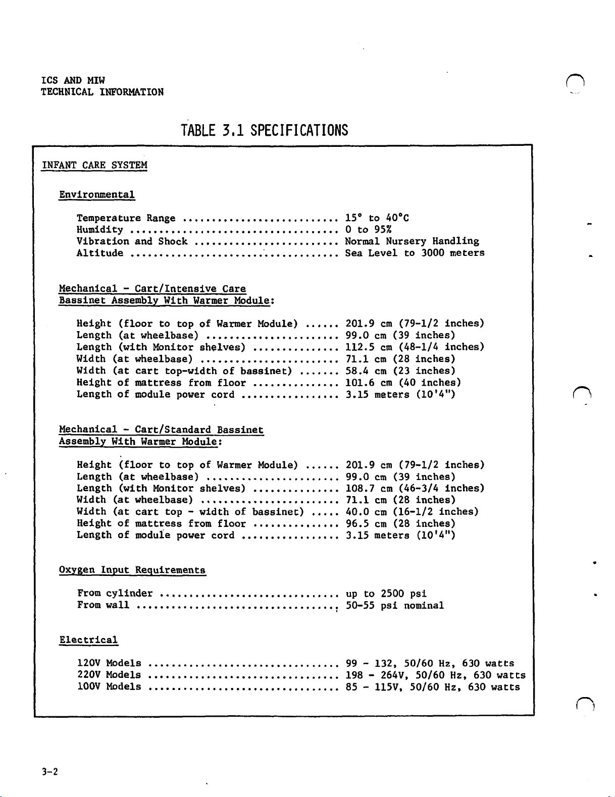
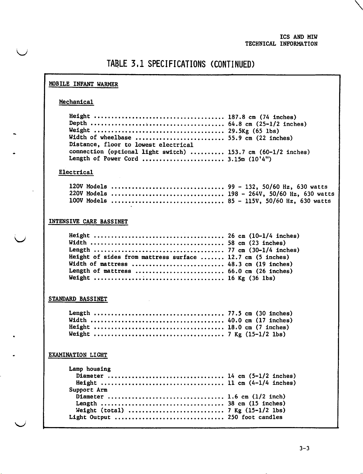
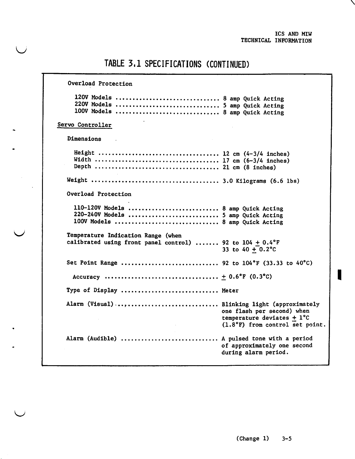
3,1
Specifications
are
SPECIFICATIONS
provided
in
for
Table
the
Air-Shields®
3.1.
SECTION
TECHNICAL
INFORMATICN
Infant
3
Care
>
System
and
Mobile
Infant
Warmer
3-1
ICS
AND
TECHNICAL
MIW
INFORMATION
INFANT
CARE
SYSTEM
Environmental
Temperature
Humidity
Vibration
Altitude
Mechanical - Cart/Intensive
Bassinet
Height
Length
Length
Width
Width
Height
Length
.oo。。
and
.....0
Assembly
(floor
(at
wheelbase)
(with
(at
wheelbase)
(at
cart
of
mattress
of
module
TABLE
Range
Monitor
........0000000
Shock
1000000000000,
With
to
top
top-width
power
3.1
SPECIFICATIONS
..........
Care
Warmer
of
Warmer
........
shelves)
......,......,....
of
from
floor
cord
sors
sos...
Module:
Module)
.vv
...........
bassinet)
...............
........
00000000000
κ... 0 to
«...
......
....
.......
.......
coco.
000.
15°
Normal
Sea
Level
201.9
99.0
112.5
71.1
58.4
101.6
3.15
to
40°C
954
Nursery
to
cm
(79-1/2
cm
(39
inches)
cm
(48-1/4 inches)
cm
(28
inches)
em
(23
inches)
cm
(40
meters
(10'4")
Handling
3000
meters
inches)
inches)
Mechanical - Cart/Standard
Assembly
Height
Length
Length
Width
Width
Height
Length
Oxygen
From
From
Electrical
120V
220V
100V
With
(floor
(at
(with
(at
(at
of
of
Input
cylinder
wall
Models
Models
Models
Warmer
to
wheelbase)
Monitor
wheelbase)
cart
top - width
mattress
module
Requirements
................4.+.+4
....................
...,.........
.............
...........
Module:
top
of
............
shelves)
.............
from
power
cord
sos.
Bassinet
Warmer
floor
ee
correa
Module)
ㄴㄴ,
...............
corses...
of
bassinet)
.......,.,..,..
....,.......,....
css
„сень...
.......
......
.....
0000...
see,
ㆍ,
201.9
,
99.0
108.7
71.1
40.0
96.5
3.15
Up
50-55
99 - 132,
198 - 264V,
85 - 115V,
cm
cm
см
cm
cm
cm
meters
to
2500
psi
(79-1/2
(39
inches)
(46-3/4
(28
inches)
(16-1/2
(28
inches)
(10'4")
psi
nominal
50/60
50/60
50/60
inches)
inches)
inches)
Hz,
630
Hz,
630
Hz,
630
watts
watts
watts
TECHNICAL
ICS
AND
MIW
INFORMATION
MOBILE
Mechanical
Electrical
INTENSIVE
INFANT
Height
Depth
Weight
Width
Distance,
connection
Length
120V
220V
100V
Height
Width
Length
Height
Width
Length
Weight
...............0%0.0.00
of
Models
Models
Models
CARE
..........2.
of
TABLE
WARMER
......00000
..........c
wheelbase
floor
(optional
of
Power
................
0008955690
.................%.cc...«..........
BASSINET
......oooooooooooorororosoroccroso
..........
of
sides
mattress
of
mattres8
......
3,1
SPECIFICATIONS
0001000000000
c...
to
Cord
0.0.0..
0...
from
....oooooooooomoomoomooooos
0...
...............
lowest
....oooooooooomosorrroos»
electrical
light
........,.............,
.......0c.
mattress
switch)
06000505
......0
と と すす
000000000
sss...
essere
..........
cc..
..«.“..“00......
se
000
0...
surface
(CONTINUED)
すす
すす
の
.
187.8
00
64.8
..
29.5Kg
-
55.9
153.7
.
3.15m
99 - 132,
če
oe
198 - 264V,
85 - 115V,
....
26
soso.
eco.
.......
00s
ee
oe
58
77
12.7
48.3
66.0
16
cm
(74
cm
(25-1/2 inches)
(65
lbs)
em
(22
inches)
em
(60-1/2
(10'4")
50/60
50/60
50/60
cm
(10-1/4 inches)
cm
(23
inches)
cm
(30-1/4 inches)
cm
(5
inches)
cm
(19
inches)
cm
(26
inches)
Kg
(36
lbs)
inches)
inches)
Hz,
Hz,
Hz,
630
630
630
watts
watts
watts
STANDARD
EXAMINATION
BASSINET
Length
Width
Height
Welght
Lamp
Diameter
Height
Support
Diameter
Length
Weight
Light
...o.ooooomomooororms<o
.........040.0.0.
„......
.ov
LIGHT
housing
® の の の
Arm
.oo。。...。。。
(total)
Output
со
600000900000
の の の の の
.....ccccccccrrseraccos
....oooooooo.o»o.
すす と チチ と すす と すす
00.0..
еооониино
の è è è se s è è è 6 è è è è € è
,..。........。.............。
00.0 00..
нос
ьа
ооо
00000042
v.s...
0000
ово
0 0
0 6 è e
.......
вене»
すす
0...
d
+ €
006€
.....
77.5
40.0
18.0
7
Kg
14
11
1.6
38
7
Kg
250
cm
cm
cm
(15-1/2
cm
(5-1/2
cm
(4-1/4
cm
cm
(15
(15-1/2
foot
(30
(17
(7
(1/2
inches)
candles
inches)
inches)
inches)
lbs)
inches)
inches)
inch)
lbs)
3-3

ICS
AND
TECHNICAL
MIW
INFORMATION
WARMER
RECEPTICAL
GAS
CONSOLE
MODULE
Warmer
Length
Width
Height
Length
Width
Height
Weight
Voltage
Width
Depth
Height
TABLE
(EXCLUDING
Housing
tons
る と の の の る の の の の eo の の の の の の の の る の の る の の の の の の の の の を の の の
ee
も の の の
BOX
(120
офъю
® 0 0 è 00
ess.
る
ee
eo
eres
.0
0.0.0000
(Including
€ 0 60000
のち
Vac)
ооо
06 0 0
se
らち
оо
3,1
SPECIFICATIONS
SUPPORT
の の
ep の あの の ちら
ооо о ооо
00
6 è e の の の 0 の の の の の の の の の を の らら
оо
ооо
cone
too
00
2020090000050
Outlet
0
e の も
の の è €
POST)
00m
もち
の る の の の る
во
ооо
ооо
ооо
0a 0 0
Fittings)
00 の è € a è è e è è è 0
950.0
あら の らら の の の の の の の
ов
оо
ооо
ооо
оо
оо
O...
0a
q
000:
0:0 0:0 cc:
.........
(CONTINUED)
56
27
の
15
る の の を
....
ce
39
4.5
9
3
Kg
120
30
9
10
cm
em
соо
ооо
ee
cm
(22
cm
(10-1/2
cm
(6
inches)
cm
(15-1/2
cm
(1-3/4
(3-1/2
(6-3/4
Vac @ 10
cm
(12
(3-1/2
cm
(4
inches)
inches)
inches)
inches)
inches)
inches)
lbs)
amp
inches)
inches)
max.
Inputs
OXYgen
Air
Suction
Color
Output
Input
ooonoorocccosomoncrrrasonsosssa
sense
CC
Code
.....0010000%%
..2
0000000002000:
Hoses
во
2000000
CONTROLLERS
Manual
Controller
Length
Width
Height
Weight
® 0
00006
®
06 0 0 0 0
....
...
®
0008808600
086
00006
sn
ооо
ооо соо
0:
00000000
00
08 è 0 è 0 è è è 0
0 0
04
08
00e
0500000:
-00
è
000
604066400
ооо
осо
G:
0000000:
00400000000
00€ © 000000
ооо
00:
..........
55
psi
(maximum)
55
psi
(maximum)
ооо
.....
ec
noc.
c:
1
atmosphere
Inlet
Yellow-Air,
White-Suction
Pneumatic
with
1.5
with
9.6
15.6
9.1
0.61
Hoses
check
or
3.1m
or
without
cm
(3-3/4
cm
(6
cm
(3-1/2
Kilograms
and
Green-0,,
-
DISS
valves
(5
inches)
inches)
inches)
Front Panel
fittings
or
10
feet)
DISS
fittings
(1-1/2
1bs)
3-4
TECHNICAL
ICS
AND
MIW
INFORMATION
TABLE
Overload
Servo
Dimensions
Weight
Overload
120V
220V
100V
Controller
Height
Width
Depth
110-120V
220-240V
100V
Protection
Models
Models
Models
oe
ооо
0000000...
ns
Protection
Models
Models
Models
3.1
SPECIFICATIONS
............
......
.............
の の る
る の の
ооо
ох
оо
ce
® è 00 00
......
ce.
ss
の
ооо
“oco
0000880608
o..e.n..
nn.
+...
<
0006 è 09004809000
se
0040000606080
999
もち の の る の る の の るる る の
(CONTINUED)
porn.
once...
eus
ON
oe
..o
@
8
5
8
12
17
21
3.0
8
5
8
amp
Quick
amp
Quick
amp
Quick
cm
(4-3/4
cm
(6-3/4
cm
(8
Kilograms
amp
Quick
amp
Quick
amp
Quick
Acting
Acting
Acting
inches)
inches)
inches)
(6.6
Acting
Acting
Acting
lbs)
Temperature
calibrated
Set
Point Range
ACCUTACY
Type
of
Alarm
Alarm
(Visual).。。
(Audible)
Indication
using
«ο»
Display
front
......
666665.
ооо
Range
panel
10000000
6..ς
оо
ооо
vs。
(when
control)
000000000000
se
фо о ооо
осс
.......
る
を る と っ の る か
92
to
104 + 0.4°F
33
to
40 + 0.2°C
92
to
104°F
+
0.6°F
Meter
Blinking
one
temperature
(1.8°F)
À
pulsed
of
approximately
during
(0.3°C)
light
flash
from
tone
alarm
(33.33
per
deviates + 1°C
control
with a period
period.
to
(approximately
second)
set
one
second
40°C)
when
point.
(Change
1)
3-5
ICS
AND
TECHNICAL
MIW
INFORMATION
3,2
3,2,1
This
THEORY
section
Warmer
Manual
Servo
Servo
OF
GENERAL
contains
Module
Controller
Controller
Controller
OPERATION
Resuscitation/Aspiration
3,2,2
The
theory
each
3,2,3
The
Manual
trigger
and
C2
vide
of
the
WARMER
of
controller.
MANUAL
Controller
which
provide
maximum
high
frequency
MODULE
operation
CONTROLLER
sets a consistant
the
to
minimum
functional
(SC78-1)
(SC78-2)
of
controls
variable
heater
harmonics
descriptions
System
(REFER
the
Warmer
(REFER
the
trigger
phase
output.
produced
TO
FIGURE
Module
TO
Warmer
is
FIGURES
Module
level
within a half
Li
and
by
the
the
of
7,8)
explained
Heater.
for
Triac
line
C3
provide
switching
following
in
7,1
AND
Q1
(2.
cycle
to
effective
Triac
components:
conjunction
with
7.4)
is a bidirectional
RI,
R2, R3,
fire
Q2.
Ql
CI,
and
to
attenuation
..
pro-
3.2.4
Servo
Control
Manual
to
sense
panel
The
skin
skin
of
approximately
ISC
Mode
sense
meter
The
control
physician.
proportionally
maintain
The
unit
ature
occurs,
skin
The
audible
SERVO
Controller
(ISC)
Mode
the
meter.
temperature
temperature
utilizes a skin
the
which
a
is
deviations
the
temperature
CONTROLLER
(SC78-1)
mode.
utilizes a skin
skin
skin
contains
point
The
stable
equipped
audible
alarm
temperature.
is
prescribed
1°F
above
temperature.
a
is
adjustable
sensed
increases
skin
with a visual
of + 1°F
alarm
returns
can
be
(SC78-1)
functions
temperature
manually
by
the
the
control
temperature
The
temperature
skin
temperature
or
decreases
temperature.
(0.6°C)
will
sound
to
within + 1°F
silenced
in
The
skin
adjustable
attending
probe
skin
temperature
control
to
the
the
and
from
and
while
(REFER
either a manual
probe
To
which
temperature
with a front
physician
point
temperature
audible
the
setting.
which
point
is
relayed
Warmer Module
is
indicator.
alarm
control
the
alarm
(0.6°C),
special
procedures
is
prescribed
to
point.
light
the
FIGURES
or
an
Infant
is
attached
is
displayed
panel
with a maximum
attached
displayed
the
system
alarm
to
controller
heater output
which senses
When
will
system
are
7.2
AND
Servo
to
the
on a front
control
the
infant
on a front
by
the
attending
which
the
deviation
flash.
will
performed.
7.5)
infant
to
the
temperature
to
panel
to
temper-
When
the
reset.
The
initial
until
The
theory
PCB
JA
PCB
1A
control
a
decrease
of
contains
circuits.
warm-up
in
operation
the
alarm
temperature
power
(while
on
a
supply,
PCB
below
of
0.4°C
basis
alarm
the
low
is
sensed
is
described
driver,
alarm
triac
point)
by
the
in
control,
TECHNICAL
may
probe.
the
following
be
and
manual
ICS
AND
MIW
INFORMATION
disabled
paragraphs.
POWER
Power
of
across
C5
an
SUPPLY
for the
Tl.
each
and
C6
output
regulator
A
+7.8
Volts
ALARM
The
TRIAC
The
MANUAL
The
PcB
DRIVER
alarm
CONTROL
triac
CONTROL CIRCUIT
manual
2A
The
secondary
half
is
voltage
with
driver
control
control
electronics
of
the
+20
and
of
an
output
dc
supply
CIRCUITS
circuits
CIRCUIT
circuit
circuit
of
Tl
secondary.
-20
Volts
+11.3
voltage
voltage
are
is
is
supplied
is
Volts
described
described
is
described
center
dc.
dc
of
is
generated
through
tapped
The
011
+
10%.
-11.3
under
under
under
P2,
with
rectified
800
CR16
(12
Volts
by
R60,
PCB
PCB
PCB
Fl,
and
approximately
filtered
provide
and
CRI7
dc
+
10%.
CR18,
2A
High-Low
2A
Phase-Angle
2A
Phase-Angle
Sl
to
de
voltages
a
series
provide
CR19,
Alarm
the
primary
15
V
regulator
a
series
and
CR23.
Circuits.
Control
Control
rms
across
with
Circuits.
Circuit.
PCB
2A
contains
Initial
TEMPERATURE
The
used
R85,
(1C2,
92°F
ICl
R5
to
IC2
control,
output
and
Warm-up
infant's
in
conjunction
R95,
and
to
104°F
is
an
and
R7.
the
initial
is
an
at
HI-LO
MEASURING
and
fed
operational
The
op-amp
R14.
pin 6 of
alarm
the
Temperature
Low
Alarm
CIRCULT
temperature
with a bridge
R100.
to
(33.3°C
output
warm-up
The
circuit,
the
temperature
used
gain
IC2
The
amplifier
in
Disable
is
voltage
to
40°C).
at
pin 6 of
LO-alarm
the
range
is
applied
and
Measuring
Circuit
sensed
circuit
output
meter,
with a gain
disable
inverting
is
30-40
to
the
temperature
Circuit,
and
using a temperature
consisting
of
the
displaying
of
ICl
is
applied
circuit
mode
with
determined
the
temperature
record
High-Low
the
Phase-Angle
bridge
a
5.
This
to
via
an
by
temperature
R65.
adjustable
circuit.
probe.
of
R1
is
amplified
gain
the
input
R11,
meter,
Alarm
Control
The
through
range
is
determined
of
front
R13,
and
phase-angle
Circuit,
Circuit.
probe
R4,
R84,
by
1С1,
of
IC2
and
panel
R14.
control
is
by
also
gain
The
IcS
AND
MIW
TECHNICAL
voltage
The
being
(33.3°C
sensed
to
output/input
per
°C).
R15
and
R16
is
applied
INFORMATION
6
pin
at
the
by
ratio
the
of
40°C),
divide
to
the
input
IC2
of
temperature
voltage
millivolts
400
this
0-4.8 volts
of
IC3.
will
level
linearly
be
probe.
will
de
The
Over
be
°F
per
down
output
proportional
display
the
0-4.8
of
volts
temperature
to a Zero
of
IC3
is
the
to
range
This
dc.
(716
to 1 volt
not
used.
temperature
92-104°F
of
gives
millivolts
de
level
an
which
R17 and R88
When
The
by
full
35,
the
scale
output
depending
is
negative
The
output
probe)
R86
is
checked
bridge
HIGH-LOW
The
HI-LO
The
HI-LO
control
face
R20
(Red
provides a voltage
(33.3°C
IC4,
IC6.
IC8,
mately
The
The
the
334
Therefore,
output
dc
to
+10
(Q8
and
pulse
The
approximately
audible
provide current
voltage
reading
voltage
assuming
upon
over
voltage
is
typically
switched
to
produce
offset
ALARM
alarm
alarms
point
Pointer),
to
40°C).
output
output
LO
alarm
millivolts.
when
of
IC8,
volts
Q9),
alarm
of
35
the
the
into
to
prevent
CIRCUITS
circuit
are
setting.
of
of
the
the
dc.
which
limiting
pin 6 of
of
104°F
at
pin 6 of
is
the
setting
(40°C)
gain
of
IC2
ICI
of
R14.
is
IC2.
displayed temperature
of
the
+320
the
sufficient
consists
set
The
and
control
of
This
voltage
IC4
and
IC6
is
voltage
voltage
LO
alarm
This
drives
two
(2)
may
be
bridge
to
bridge
the
to
0-4.8
applied
comparator.
This
voltage
the
deactivated
circuit's
+300
millivolts
via
offset
temperature
of
activate
control
is
volts
of
the
output
is
equivalent
at
pin 6 of
comparator,
will
visual
times
per
to
the 1 milliampere
4.8
volts
on
the
will
be
This gain
The
polarity
534
when
for
IC4,
at
+1°F
point
provided
dc
0-4.8
of
to
IC7,
R45 and R46
IC6
will
turn
and
second
using
dc,
R88
meter.
the
output
may
of
the
range
left
of
leg
92-104°F
(RI,
for a temperature
meter
calibration
100°F meter
meter
IC6,
when
volts
IC7,
or
setting
by
the
IC2
are
the
from
-1°F
R20
dc
HI
hitting
IC8,
is
and
control
is
fed
alarm
generate a voltage
to a temperature
is
-334
millivolts
switch
on
audible
(0.3
010,
alarms
second
from
starting
$2.
full
scale
is
adjusted
voltage
vary
voltage
of
between
at
(33.3°C
R3,
and
range
is
deflection.
the
left
Q7,
08,
09,
(0.55°C)
indicated
R19.
also
to a comparator
voltage
through
ON,
relative
on
The
wiper
point
at
is
the
comparator,
of
1°F
or
approximately
a
multivibrator
Q7.
and
0.2
meter.
to
give
1C2
divided
30
and
pin 6 of
to
R100
and
of
required
R87
provides
meter
and
the
meter
set
output
amplifier,
of
(0.55°C).
greater,
The
second
a
40
IC1
40°C).
the
92-104°F.
or
stop.
Q10.
to
the
arm
of
for
92-104°F
pin 6 of
and
approxi-
the
-10
volts
alarms
OFF).
a
te
When
alarm
again
temperature
than
the
will
+334
activating
voltage
be
at
activated.
millivolts,
returns
the
the
the
alarms.
to
within
output
When
output
of
the
The
+
IC6
of
alarms
1°F
is
voltage
IC7
will
(0.55°C)
within
at
the
switch
are
automatically
of
-334
output
the
to
from
set
+334
of
IC6
-10
reset
control
millivolts,
becomes
to
+10
volts
when
point.
no
greater
de,
the
TECHNICAL
ICS
AND
MIW
INFORMATION
output
The
control
circuit.
switched
effect
In
reaches
INITIAL
One
the
IC11,
The
amplified
1°F
WARM-UP
function
initial
and
output
pin 6 of
temperature
sensed
phase
IC10,
IC9
for a long
emitter
This
(output
actually
The
maximum
temperature
is
C9,
decreases
of
stored
of
stored
peak
IC7,
of
This
on.
turns
it
(0.55°C)
LOW-ALARM
of
the
warm-up
013
through
voltage
by
IC9.
IC9
while
probe.
proceeding,
013,
and
from
period
Q14.
temperature
IC9)
are
the
real-time
voltage
voltage
HI
the
When
+10
disables
power
off
higher
controller
of
the
021.
of
101
The
fixed
at
77°F
The
output
of
77°F - 104°F
the
Ql4
are
any
maximum
of
time,
voltage
fed
voltage
is
attenuated
level
volts
the
to
than
comparator
de
trigger
the
the
CIRCUIT
alarm
DISABLE
provides
infant.
and a fixed
bias
is
(25°C)
simulated
voltage
maximum
used
positive
in a configuration
positive
and
this
(Q14
to a voltage
which
through
reached
is
is
present
circuit
for
circuits
bias
when
point
disabling
voltage
heater
control
The
adjusted
temperature
of
IC9
(25 - 40°C).
voltage
voltage,
stored
voltage
emitter)
comparator
is
changing
R70
and
during
the
also
at
the
which
the
setting
which
from
to
give a +2
will
be
While
reached
such
this
level
and
the
IC1l.
relative
R71,
warm-up
into
fed
output
feeds
measured
the
LO-alarm
do
this
R63
is
+2
to
the
will
that
peak
is
actual
The
to
and
is
cycle.
phase
the
of
IC7,
triac,
the
temperature
on
the
are
is
summed
volts
dc
provided
+8
Volts
initial
be
if
the
voltage
available
temperature
output
the
sensed
equal
04
meter.
during
IC9,
and
output
for
de
warm-up
stored
output
is
stored
at
of
IC9
to
95%
angle
is
Q6.
IC10,
at
the
for
a
on
C9.
of
the
voltage
is
temperature.
of
the
As
long
as
maximum
dc
keeps
peak
comparator,
When
the
has
come
Q15
to
turn
its
normal
016
is
driven
memory
With
that
During
+10
warm-up
control
by
Q16
is
Q17
017
the
volts
020,
is
subsequently
period
point,
which
disable.
the
real-time
stored
Q15
turned
thereby
initial
to
mode.
within
off.
warm-up
With
from a flip-flop
initially
on,
Q16
is
is
initially
initial
dc.
This
is
over.
IC3's
in
turn
voltage
voltage,
on,
which
disabling
period
1°F
(0.55°C)
Q15
set
with
off,
allowing
turned
warm-up,
voltage
As
output
resets
switched
the
in
the
has
of
off,
this
(Q17
Q17
on
by
IC8,
is
sensed
the
temperature
switches
the
on,
(temperature)
output
turn
of
grounds
alarm.
been
completed
the
control
allows
and
Q18)
turned
Q15
to
on
disable
producing
the
LO
alarm
by
Q20
to
-10
flip-flop,
which
disables
is
IC11
is
the
point,
the
LO-alarm
which
when
power
the
an
initialization
comparator,
to
determine
reaches
volts
turning
the
greater
+10
output
and
Q16
serves
is
LO-alarm.
within
dc.
on
function
than
Volts
the
dc,
of
IC8,
sensed
is
switched
circuit
as a memory.
applied
output
when
1°F
This
voltage
018,
and
of
95%
of
This
the
LO-alarm
temperature
to
operate
to
the
Q19
assures
pulse
the
at
voltage
initial
(0.55°C)
is
turning
the
LO-alarm
the
+10
volts
on
causing
in
This
controller.
power-up.
is
of
the
sensed
off
017.
ICS
AND
TECHNICAL
MIW
INFORMATION
However,
activated
temperature
If
the
output
of
IC1l
will
the
output
ature
returns
remainder
One
other
alarms
are
disables
disable
feature
PHASE-ANGLE
Power
output
to
from
difference
setting
R22,
the
is
and
triac,
an
additional
if
the
sensed
sensed
during
voltage
switch
voltage
of
the
point
to
the
initial
relative
of
disabled.
the
alarms
after
CONTROL CIRCUIT
the
heating
IC2
and
in
input
amplified
R89.
This
Q6.
feature
temperature
the
of
IC9
to
-10
IC8
(+10
stored
warm-up
to
021,
while
021
calibration
element
the
output
voltage
by a gain
bias
voltage
initial
falls
volts
level,
the
022,
and
is
from
of
the
ever
below
DC,
turning
Volts
dc)
the
period.
alarms;
and
023
023
completed.
is
controlled
from
IC4
the
real-time
of
5. A bias
sets
overall
falls
warm-up
95%
to
LO-alarm
during
do
this
insure
through
are
the
initial
circuit
below
period.
of
the
off
Q15.
activate
again
meter
in
the
correct
fed
differentially
temperature
voltage
conduction
allows
0.4ºC
stored
of
voltage,
This
the
alarm.
becomes
calibration
conjunction
operation
IC5,
Q3,
Q4,
and
is
also
LO-alarm
the
maximum
the
immediately
If
the
disabled
using
with
S3B.
of
Q5,
and
into
IC5.
the
control
generated
phase-angle
to
be
output
allows
temper-
for
S3,
the
Q6.
by
for
M
peak
the
the
022
LO-alarm
The
This
point
R21,
The
output
several
warm
the
Volts
capacitor,
When
the
pulse
Q4
of
done
de at
the
unijunction
transformer
and
Q5
the
by
(36.7°C)
band
The
(90%)
and
The
source
Cl
is
10%
manual
which
different
at
3.2.5
voltage
volts
either
infant.
the
Cl.
voltage
are
used
input
voltage
setting
temperature.
width
applied
power
when
control
may
SERVO
at
pin 6 of
direction,
This
output
emitter
level
of
on
transistor
T2,
which
to
reset
(60
Hz).
the
control
R22
the
the
the
of
varied
thereby
of
sensed
control
when
be
rates
CONTROLLER
IC5
voltage
Q2
controls
the
capacitor
will
triggers
the
Initial
point
adjusted
is
phase-angle
the
sensed
temperature
heater
through
changing
(SC78-2)
is
approximately
depending
and a fixed
the
trigger
the
charge
on
setup
to
98°F
to
temperature
provided
is
R28.
the
upon
amount
reaches
and
discharge
triac
Cl at
of
(36.7°C)
50%
a
set
is
is
+0.25°F
is
by
The
various
conduction
(REFER
+9
volts
the
amount
voltage
of
current
approximately
the
into
conduction.
the
beginning
the
conduction
and
simulating a 98°F
conduction
gain
the
by
-0.5°F
Ql.
(.27°C)
from
This
levels
phase-angle
To
FIGURES
dc
and
of
power
of
approximately
which
+6.8
capacitor
of
each
phase-angle
of
for
IC5.
angle
from
set
the
constant
a
is
of
current
7,3,
will
required
charges
volts
into
half
the
Full
set
point.
the
of
7.6,
change
+8.5
the
de
the
cycle
is
triac.
power
point,
current
charge
triac.
AND
to
o
7.7)
The
to
ature
3-10
SC78-2
the
is
Servo
infant,
displayed
Controller
to
sense
on a front
utilizes a skin
the
skin
temperature
panel
meter
temperature
of
the
which
contains
probe
infant.
a
which
The
skin
temperature
is
attached
temper-
control
A
 Loading...