

SERVICE
Isolette®
MANUAL
Infant
From
Hill-Rom
Incubator
Air-Shields
For
Parts
USA
International:
(800)
or
Technical
445-3720
Canada
Contact
Product
Assistance
(800)
your
distributor.
No.
C2000
267-2337
man223rf

lsolette®
Infant
Incubator
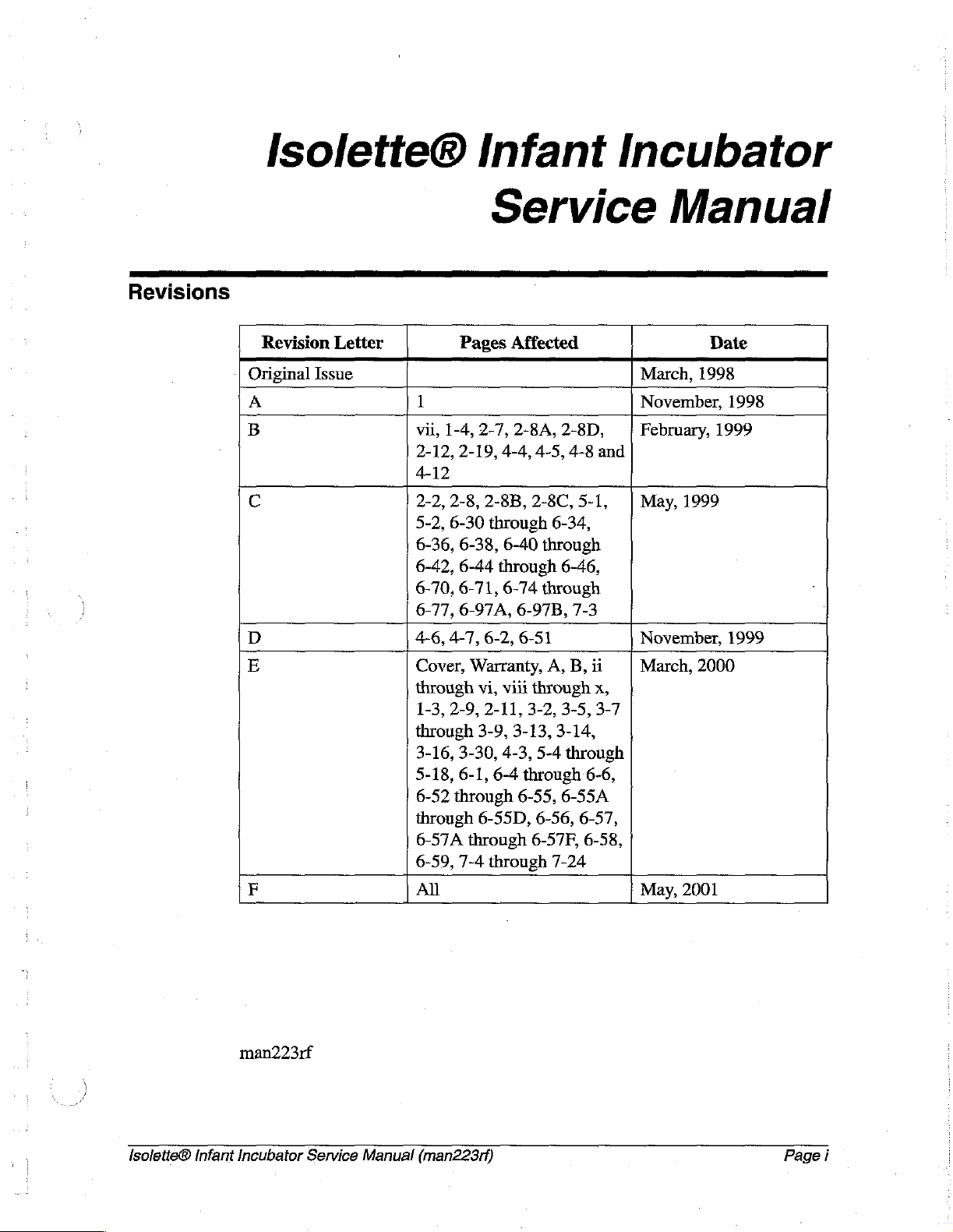
Revisions
Service
Revision
Original
A
B
ο
o
E
F
Letter
Issue
Pages
1
vii,
1-4,
2-12,
2-19,
4-12
2-2,
2-8,
5-2,
6-30
6-36,
6-38,
6-42,
6-44
6-70,
6-71,
6-77,
6-97A,
4-6,
4-7,
Cover,
through
1-3,
2-9,
through
3-16,
3-30,
5-18,
6-1,
6-52
through
through
6-57A
6-59, 7-4
All
through
Affected
2-7,
2-8A, 2-8D,
4-4,
2-8B,
2-8C,
through
6-40
through
6-74
6-97B,
6-2,
6-51
Warranty,
vi,
viii
through
2-11,
3-2,
3-9,
3-13, 3-14,
4-3,
6-4
through
6-55,
6-55D,
6-57F,
through
4-5,
5-4
6-56, 6-57,
4-8
and
5-1, | May,
6-34,
through
6-46,
through
7-3
A,
B,
ii
x,
3-5,3-7
through
6-6,
6-55A
6-58,
7-24
Manual
Date
March,
November,
February,
November,
March,
May,
1998
1998
1999
1999
1999
2000
2001
lsoletie®
Infant
man223rf
Incubator
Service
Manual
(man223rf)
Page
i
Revisions
©
2001
by
Hill-Rom
No
part
of
this
means,
electronic
information
Hill-Rom
Seventh
First
Services,
Edition
Printing
text
shall
or
or
retrieval
1998
Services,
be
reproduced
mechanical,
system
Inc.
(Hill-Rom).
Inc.
ALL
including
without
RIGHTS
or
transmitted
photocopying,
written
permission
RESERVED.
in
any
recording,
from
form
or
by
or
any
by
any
Printed
Air-Shields®
Critter
Hill-Rom
Hill-Rom®
Isolette®
in
the
USA
is a registered
Covers®
Air-Shields™
is a registered
is a registered
Kleenaseptic®
Loctite®
Motorola®
Oilite®
Teflon®
is a
registered
is a
is a
registered
is a
registered
Company.
trademark
is a registered
is a
trademark
trademark
trademark
is a
registered
trademark
registered
trademark
trademark
trademark
of
trademark
of
of
of
Hill-Rom
trademark
of
Loctite
of
of
Beemer
of
E.
I.
Hill-Rom
of
Hill-Rom
Hill-Rom
Hill-Rom
Services,
of
Metrex
Corporation.
Motorola,
Precision,
du
Pont
Services,
Services,
Services,
Services,
Inc.
Research
Inc.
Incorporated.
and
de
Nemours
Inc.
Inc.
Inc.
Inc.
Corporation.
and
Page
ii
Velcro®
is a registered
corporation).
The
information
Hill-Rom
contained
The
warranty
makes
warranty
makes
in
only
product
accompanying
no
other
of
merchantability
this
trademark
contained
no
commitment
manual.
warranty
the
warranty,
in
this
intended
bill
of
express
or
fitness
Isoleite®
of
Velcro
manual
to
update
by
sale
or
implied,
Industries,
is
subject
or
Hill-Rom
to
the
for a particular
Infant
Incubator
to
keep
current,
is
the
original
and
purchaser.
in
particular,
purpose.
Service
BV
(a
Dutch
change
the
express,
Manual
without
notice.
information
written
Hill-Rom
makes
no
(man223rf)

Revisions
Additional
To
order
parts
copies
additional
order
for
of
part
this
manual
copies
number
can
of
this
manual,
man223rf.
be
obtained
call
from
(800)
Hill-Rom.
445-3720,
and
place
a
lsoletie®
Infant
Incubator
Service
Manual
(man223rf)
'
Page
iii

Revisions
NOTES:
Page
iv
Isoletie®
Infant
Incubator
Service
Manual
(man223rf)

Table
of
Contents
Chapter
1:
Introduction
Purpose
AUdience............
Organijization
Chapter
Chapter
Chapter
Chapter
..
1:
Introduction.
2:
Troubleshooting
3:
Theory
4:
Removal,
ChapterS:Partslist...............
Chapter
Chapter
Typographical
Technical
Introduction.
6:
General
7:
Accessories . .............................:............
Conventions
Definitions
......,..................,,,..444444
OvervieW
4.0000
aussi
nerenin
..........................................
Procedures
of
Operation
Replacement,
Procedures
..........................................
...............................................
....................................
.....................................
..............................
and
Adjustment
1...
eseri
Procedures...........
0 0 enter e nee
K
ннання
n
nee
1-3
1-3
1-3
1-3
1-3
1-3
1-3
1-4
1-4
1-4
1-5
1-6
1-8
1-8
Operating
Features.
Oval
Mattress
Pedestal
Oxygen
Humidity
Weighing
Specifications
Physical
Electrical
Oxygen
lsolette®
Infant
Precautions.
Access
Tilt
Stand
Control
System
Platform
......................................,4...........
Description.
Description
Control
Incubator
...........................................
Doors
Mechanism
...........................................
...............................:
Assembly
System
(Optional).
(OptionaD
................
(Optional)
...................................
..............................
.
eserin
ων
ων
ωω
κε νε
.....................,,...............,....
...........................................
Description.
Service
.....................................
Manual
(man223rf)
erekes
нь.
ενω
ρω νε ων ων
1-8
1-8
1-8
1-8
1-8
1-8
1-8
1-9
1-10
1-10
1-11
1-12
Page
v

Table
of
Contents
Regulations,Standards,andCodes.................................
Model
ldentificationandSeriesChanges...............................
SafetiyTlips.................
Warning
Chapter
GettingStarted...............
Initial
Function
Final
Alarms..............
System
Diagnostic
and
Caution
2:
Troubleshooting
Labels
Procedures
Actions
Checks
..
Actions.................
ea
High
and
Low
Air
and Skin
Alarm
Messages に に に に に に に に
Failure
Messages
Menus
...........................................
.................................................
EnteringtheDiagnosticMenus............................
emer
し
に
にし に に に に に に に に に に に に
0.
неона
öneren
Temperature
ーー ト に に に レレ
eee
eee
кения
Alarms
ーー
トト に に
に に
トト
ee
トト に トト に トー
ene
eet
eee
ニー
ence
.....................
トト
レート
トト
ーー
トト
トー
レレレ
ーー
00.
バー バー
на
nense
ene
トーーーーー
1-12
1-13
1-15
1-20
2-3
2-3
2-4
2-14
2-15
2-15
2-16
2-24
2-25
2-25
Variable
Low
Oxygen
Oxygen
Chapter
Controller
Variable
Hood/Shell
Theory
Diagnostic
System
Key
Check
Data
Information
Test
Display....................................,........
Summary
Height
Set
Temperature
Concentration
Concentration
3:
Theory
Assembly.
Height
Assembly
of
Operation
Electrical
Sensor
System
Module
Menu.
....................................
Menu
Adjustable
of
..................................,..........
Menu
...................,.......................
Pedestal/Stand
Alarm
is
is
Low
High
Activated
.......................................
...........................,...........
Will
Not
Move
Up
or
....................,..,........
Operation
.....................,.....................,...
Adjustable
Pedestal/Stand
Assembly.
.....................
.....................,...........,,.,..........
κε
νεο ρ ρω
に に に に に に に に に に に に に に に
ーー に トト
トト
トト
トト
トー トー
....................................,........
Down
ων
トー
......
εν
ων ων ων
トー
バー
2-27
2-28
2-31
2-32
2-34
2-36
2-38
2-41
3-3
3-7
3-8
3-12
3-12
3-12
Page
vi
Controller
..............
Isolette®
Infant
Incubator
een
Service
Manual
3-16
(man223rf)
Table
of
Contents
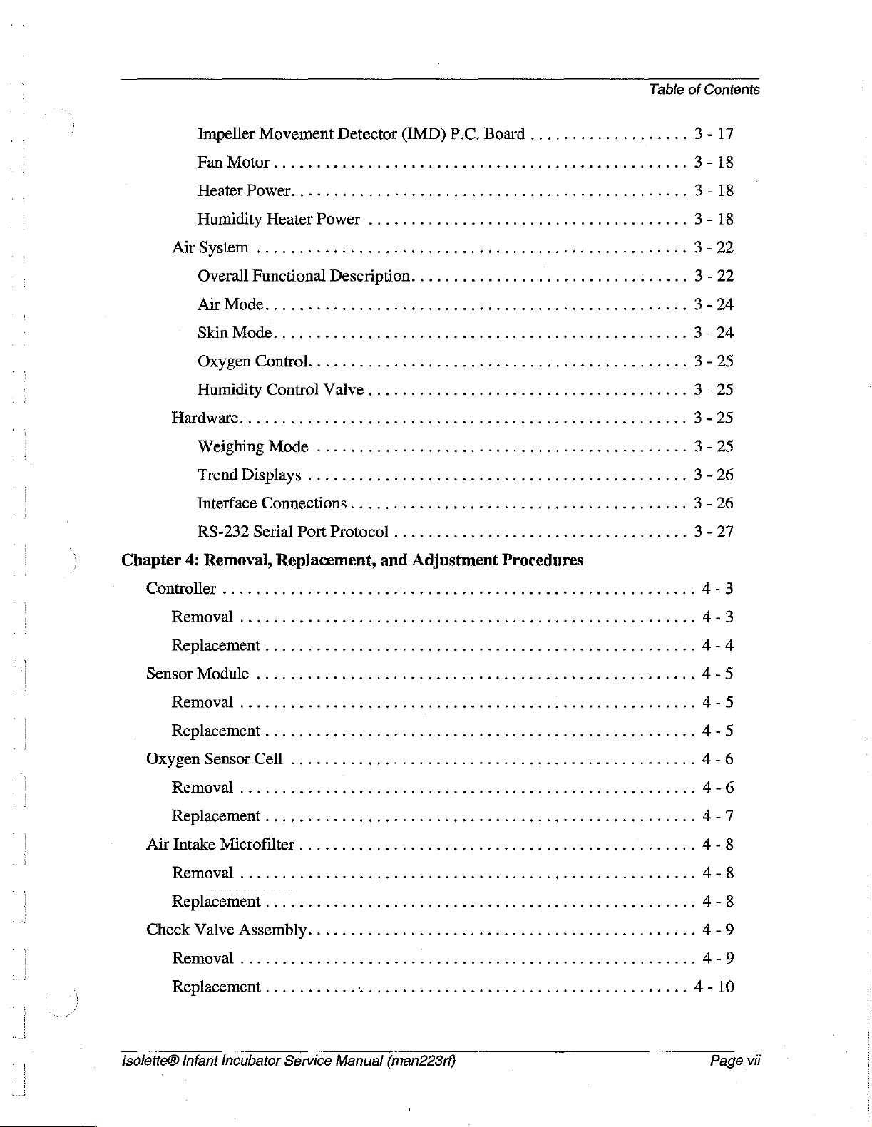
Impeller
Fan
Heater
Humidity
Air
System
Overall
ArMode.......................
SkinMode..........................
Oxygen
Movement
Detector
Motor..............
Power.
........,..........................,.....422..
Heater
Power
........,.........,.............,.....
.
Functional
Description.
Control. に に に に に し に に
(IMD)
P.C.
Board
...................
4444444444440
veverrenese
..........................:.....
een
rr
に に に に
レレ
ーーー に に
ーー に に に に に スレ に トト
トー
HumidityControlValve......................................
HardWarg,
Weighing
Trend
Interface
RS-232
Mode
Displays
Connections
Serial
Port
.............................................
......................,,..........,.....
Protocol
...................................
トート
eee
k
ーー
バー
kseee
eens
k
3-17
3-18
3-18
3-18
3-22
3-22
3-24
3-24
3-25
3-25
3-25
3-25
3 - 26
3-26
3-27
Chapter
4:
Controller
Removal
Replacement.................
SensorModule
Removal
Replacement...................
Oxygen
Removal
Replacement....................
Air
Intake
Removal
Replacement..
Check
Removal
Removal,
Replacement,
..
...................,......,,.,...4
........................
..................
Sensor
Cell
.....................,........,,.....
Microfilter
Valve
Assembiy...........................
..
..
..
and
Adjustment
0
44.44.4400
een
eee
0.
ia
ies
eee
ecran
Procedures
44e
k
essuie
ia
eee
esse
esse
4-3
4-3
4-4
4-5
K
инь
4-5
4-5
keneee
4-6
4-6
4-7
arananı 4-8
o
4-8
EEE
4-8
4-9
ann
4-9
Replacement...........
Isolette®
Infant
Incubator
Service
R
Manual
(man223rf)
ken
4-10
Page
vii


High
Dual
Model
High
Dual
Model
High
Front
Model
High
Front
Model
Access
Only)
Access
Only)
Access
Only)
Access
Only)
Table
Hood
に に に に に
Hood
Assembly
に
Assembly
with
with
Two
Two
Access
Access
Doors
Doors
(“00”
Series
иниининнинни т 5-34
(“01”
Series
..........................,.,..........,........,,....
Hood
Hood
Assembly
Assembly
with
with
Four
Four
Access
Access
Doors
Doors
ses
(“00”
(“01”
Series
Series
erkee 5 -
k
of
Contents
5-38
5-42
46
Access
Access
Access
Access
Shell
Shell
Top
Controller
Enclosure
Front
Interface/Power
Sensor
Pedestal
Pedestal
Variable
Panel
Front
Panel
Panel
Panel
Assembly
Assembly
Shell
Front
Rear
Rear
(“00”,
(“03?
Assembly
Assembly
Assembly
Panel
Assembly
Supply
Module
Stand
Stand
Assembly...................
Assembly
Assembly
Height Adjustable
Assembly
Assembly
Assembly
Assembly
“01”,
Series
(“03”
Series
(Model
(Model
(Model
Assembly
(“00”
(“01”
(“00"
(“01"
(“00"
(“01"
and
Model
Series
Series
“02”
On
Model
C2C-2
C2C-2
Only).........................,....
C2C-2
(Model
Series
Series
Pedestal
Series
Series
Model
Model
Model
Model
Series
Only)
Oniy}
Only)
.............,....
................
...................
Only)...................
Models
Only)................
Only)..........................
Only)
Stand
..............,.............. 5 -
Only)
Model
............................
C2C-2
and
Higher
Assembly.
Onlÿ)...................
0.
Only)
Models
......................
eee
Only)............
....................
...
κ
ων
5-50
5-52
5-54
5-56
5-58
5-62
5-64
68
5-70
5-72
5-74
5-76
5-78
5-82
5-86
Hood/Shell
Foot
Foot
Check
Scale
Sensor
Scale
Impeller
IV
Pole
isolette®
and
Switch
Switch
Valve
Pedestal Stand
Assembly,
Assembly,
Assembly.
Front
Rear
Assembly
........................................
Attachment
....................
.........................,..............
ννννωωω
ων
ενω
ρε ω ο
Assembly....................................,..............
Module
P.C.
Movement
Assembly
Infant
P.C.
Board
Assembly—P/N
(Accessory)..............,.........,..........
Incubator
Board
Assembly—P/N
Detector
Service
Manual
P.C.
83
600
70...........................
Board
Assembly—P/N
(man223rf)
83
005
70.....,.........,....
83
103
70........ 5 -
ων
εν ον
5 - 102
...
5-108
5-90
5 - 92
5-93
5-94
5-96
5-98
106
Page
ix
Table
of
High
Contents
Monitor
Shelf
Assembly
(Accessorÿ)
..................,.........
5-110
Swivel
Humidity
Humidity
Evaporator
Oxygen
Ventilator
Oxygen
Chapter
Drawer
System
System
System
Tank
6:
General
Reservoir
Tube
Cleaning に にし に に に し
General
Steam
Cleaning
Cleaning,
CleaningHardtoCleanSpots.........................
Disinfecting....................
Using
Cleaning
Skin
Temperature
Assembly
(Accessory)
(Accessory)
(Accessorÿ).
Support
Bracket
(Accessory).....................,..........
.........................,..,.........
(“02”
Assembly
Series
(“02"
Model
Series
Model
Onlÿ)
.................
Only)................
......,.....................,,.........
(Accessory}................,.,.,,...........
(Accessory).....................
Procedures
ュー
トト
レレレ
ーー
トー に レト トー
トト
トレ トト
トー
レレ
ーーーーーーー
.......................,.........,,,...........
ilen
Agents........,..................................
Probe . ...............................,......
ela
2
A
5-112
5-114
5-118
5-12
5 - 124
5 - 127
5-128
nnennes
6-3
6-3
6-4
6-4
6-4
6-4
6-4
Access
Humidity
Controller,
Hood,
Heater
Mattress
Air
Disassembly
Assembly
Component
P.C.
Воаг4.......
Lubricaton
Preventive
Preventive
Preventive
Door
Gaskets
Tray
Reservoir
Shell,
Sensor
Module,
Radiator
Tray,
Main
Intake
Microfilter
..
renerne
........................
Handling
.......................................,,...2.
and
Tubing
Access
...,......................,...........
and
Pedestal
and
and
Fan
Deck,
...................................,.....
Stand
Inner
Walls
Impeller.
Heater/Impeller
...............................
.................,...,.......
eee
неее
Reguiremenis....................
Maintenance
Maintenance
Maintenance
............................................
Schedule
Checklist
....................,............
.................................
Ports
.....................
...........................
Cover,
еее
ини
and
ен
Mattress
Tilt
нннна
einen
6-4
6-5
6-5
6-5
6-7
Bars 6 -
6-7
6-7
ων
6-13
6-15
6-15
6-16
6-17
6-18
6-19
7
Page
x
Isolette®
Infant
Incubator
Service
Manual
(man223rf)
Table
of
Contents
InstaHlation
and
Set-uD
し
に に に に に に に
Unpacking.....................
Assembling
Setting
Oxygen
Room
10066
Sensor
................,.......................,..,.4.02.
Up........
Calibration.
Ar 一 21%
.........................................
Oxygen
し
し に し よし に に
ΟΣΥΡΕΠ..
OxygenConcentrationTest................
Weighing
Scale
Cahbration
し
よし
CurrentleakageTest....................
SetrUp.
Procedure
Tool
Chapter
eee
and
Supply
7:
Accessories
に
に に に に に に に に に に に に
Requirements.
ーー トト に に
...........................,,.........
Accessories
ーー・ ト に
レー に ーー
トト
トー
トー
トー
トト トト
ーー
レー
0.0.
ee
に に に
ュー
ニー
に に
トト
レー に に に トト
users
e
ttre e nee 6 -
εκ
トー
トト
esse
0
iin
に 이 이 이
トト
ーー
0000
トト
トト
ニレ
eee
レト
トト
トト
ーー
トト
スィ
reserveres
トー バー
6-20
6-20
κο
εως
ος
6-2
6-24
ーーー 6 -
6-
6-27
이 이 아 이 다 6 - 28
6-29
aaa
ーー
ここ
ーー
6-29
6-29
6 - 30
20
24
25
7-3
Weighing
Installation
Removal
Охудеп
Зубет.
Installation
100%
Removal
Humidity
Installation
Removal
Humidity
Jnstallation
Removal
Scale.
еее
еее
cece
етики
eee
...................................,,,......2..2,20
Calibration
...................
System
Fixture
(“00”
Installation.
and
“01”
...............................
000
eee
SeriesModelsOnly)....................
....................,.,...........44444444e
........................,,..,.44444
System
(“02"
..
een
Series
Model
Only)
............................
0
0
ann
ous
K
eee
sseee
а
nk
7-4
7-4
7-5
7-6
7-6
7-9
7-10
7-11
7-11
7-14
7-15
7-15
7-18
Isolette@
Infant
Incubator
Service
Manual
(man223rf)
Page
xi

Table
of
NOTES:
Contenis
Page
xii
Isolette®
Infant
Incubator
Service
Manual
(man223rf)
Chapter
Contents
Chapter
Introduction
1
Purpose
Audience..
Organjization
Chapter
Chapter
Chapter
Chapter
Chapter
Chapter
Chapter
Typographical
Technical
Introduction.
Overview.
Operating
に に に
l:Introducüon........................
2:
3:
4:
5:
6:
7:
Definitions
ileri
Precautions.................................,..........
レー に し
Troubleshooting
Theory
Removal,
Parts
General
Accessories
Conventions
に に に に に
トー
トト トー
トト
トト
トー
トト
トト トト
トト
トト
トト トレ
トー
トト
cee
cee
tee
enn
erne
0
Procedures
of
Operation
Replacement,
List............................,................
Procedures
..........................:................
................................,......,..
...............................................
....................................
.................................,...
..............................
and
Adjustment
eneret
Procedures.
トット ト トー て
iie
eee
てこ
tener
rr
..........
rare
ここ
ーー
ones
1-3
1-3
1-3
1-3
1-3
1-3
1-3
1-4
1-4
1-4
1-5
1-6
1-8
1-8
1-8
Features...,.........................,.......4.444.
Oval
Mattress
Pedestal
Oxygen
Humidity
WeighingPlatform(Optiona)
Specificaflong
lsolette®
infant
AccessDoors...................
Tilt
Stand
Control
System
,
Incubator
Mechanism
Assembly
System
(Optional).
Service
Manual
......................................
......................................
(Optional)
............................,......
...........................
(man223rf)
44e
00
eee
..............................
eres
rsenee
1-8
1-8
1-8
1-8
1-8
1-8
1-9
1-10
Page
1-1
Chapter
1:
Introduction
Physical
Electrical
Oxygen
Regulations,
Model
Safety
Warning
Identification
TiDS
and
Description.
....................................,,.....
Description . ..........................................
Control
.
Caution
Description.
Standards,
and
Series
Labels
.....................................
and
Codes..
Changes
ili
aaa
...............................
eus.
........................................
1-10
1-11
1-12
1-12
1-13
1-15
1-20
Page 1 -2
Isolette®
Infant
Incubator
Service
Manual
(man223rf)
Purpose
This
operation
ordering
Audience
This
to
damage
Organization
This
manual
and
replacement
manual
observe
to
manual
provides
maintenance.
is
intended
this
restriction
equipment.
contains
requirements
It
also
components.
for
use by
can
result
seven
chapters.
for
the
Isolette®
includes
only
in
parts
lists
facility-authorized
severe
injury
Chapter
Infant
(in
chapter
to
people
1:
introduction
Incubator
personnel.
and
normal
5)
for
serious
Purpose
Failure
Chapter
Chapter
Chapter
Chapter
1:
In
addition
a
product
2:
Repair
to
gather
effectiveness
3:
This
chapter
hydraulic
4:
Procedures
Chapter 4 contains
in
chapter
Introduction
to a brief
overview.
description
Troubleshooting
analysis
information,
Theory
Removal,
procedures
of
the
describes
systems
2.
identify
repair.
of
Operation
the
application
employed
Replacement,
the
detailed
of
this
Procedures
are
contained
the
maintenance
in
this
product.
maintenance
service
in
this
of
the
mechanical,
and
procedures
manual,
chapter.
need,
chapter 1 also
Use
and
verify
electrical,
Adjustment
determined
these
the
provides
procedures
and
necessary
lsolette®
Infant
Incubator Service
Manual
(man223rf)
'
Page
1-3

Organization
Chapter
1:
Introduction
Chapier
This
parts
Chapter
Cleaning,
in
Chapter
A
Infant
accessories
5:
Parts
chapter
lists.
6:
General
preventive
this
chapter.
7:
Accessories
list
of
additional
Incubator,
List
contains
products,
is
are
also
the
warranty,
Procedures
maintenance,
that
available
included.
in
chapter
part-ordering
and
other
can
be
used
7.
Installation
procedure,
general
in
procedures
conjunction
procedures
and
illustrated
are
with
the
for
described
Isolette®
these
Page
1-4
{solette®
Infant
Incubator
Service
Manual
(man223rf)
Typographical
This
readability
examples:
+
*
*
*
Conventions
manual
Standard
Boldface
NOTE:—sets
clarification.
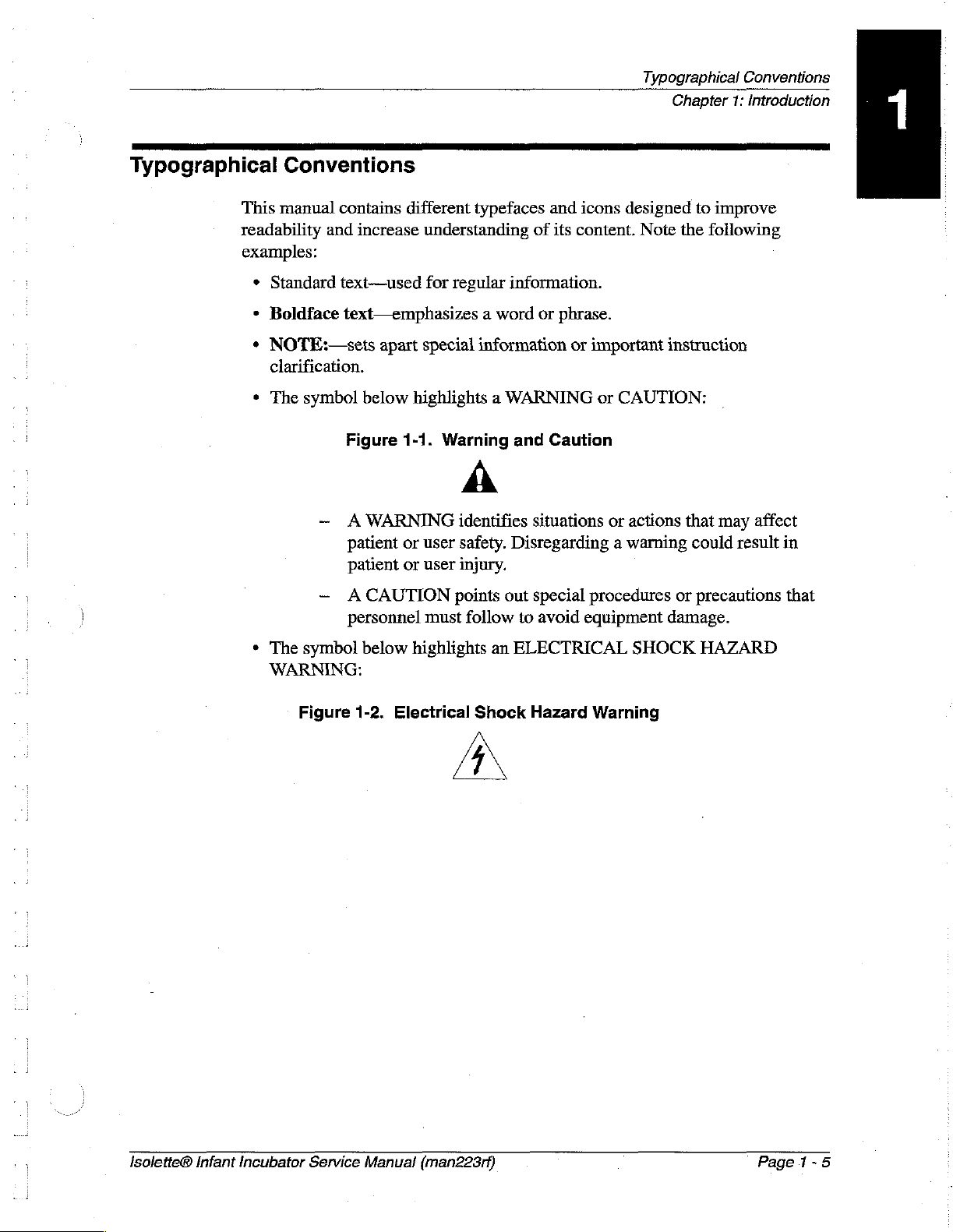
The
contains
and
increase
text—used
text—emphasizes a word
apart
symbol
below
different
understanding
for
special
highlights a WARNING
typefaces
regular
information.
information
of
or
and
icons
its
content.
phrase.
or
important
Typographical
designed
Note
or
CAUTION:
Conventions
Chapter
the
1:
Introduction
to
improve
following
instruction
+
The
WARNING:
Figure
Figure
— A WARNING
patient
patient
—
ACAUTION
personnel must
symbol
below
1-2.
1-1.
Warning
A
identifies
or
user
safety.
or
user
injury.
points
follow
highlights
Electrical
Shock
AN
and
Caution
situations
Disregarding a warning
out
special
to
avoid
an
ELECTRICAL
Hazard
or
actions
procedures
equipment
SHOCK
Warning
that
may
could
or
precautions
damage.
HAZARD
affect
result
in
that
Isolette©
Infant
Incubator
Service
Manual
(man223rf)
Page
1-5

Technical
Chapter
Definitions
1:
Introduction
Technical
Definitions
This
manual
Incubator
and
centered
Control
the
user.
Average
minimum
equilibrium.
Incubator
average
of
90°F
Temperature
of
the
Temperature
to
(12°C)
incubator
one
hour.
(32°C)
each
of
average
rise
20°F
above
contains
different
temperature—The
over
the
mattress
temperature—The
incubator
incubator
temperature
These
and
four
incubator
(11°C),
the
temperature—The
temperatures
equilibrium-—The
temperature
measurements
97°F
(36°C).
uniformity—The
points
4"
(10
temperature
rise
time—The
when
the
ambient
temperature.
technical
terms.
air
temperature
surface.
temperature
achieved
does
not
are
taken
amount
cm)
above
at
incubator
time
required
air
control
Note
the
following
at a point
controller’s
average
vary
by
the
of
the
during
temperature
condition
more
than
at
the
control
which
the
mattress
temperature
for the
incubator
surface
temperature
4"
(10
set
point
maximum
reached
1°C
over a period
temperatures
average
differs
equilibrium.
temperature
is
at
least
definitions:
cm)
above
selected
by
and
when
the
of
temperature
from
22°F
Temperature
overshoot—The
exceeds average
equilibrium
the
incubator
result
Temperature
temperature—The
temperature
Temperature
temperature—The
incubator
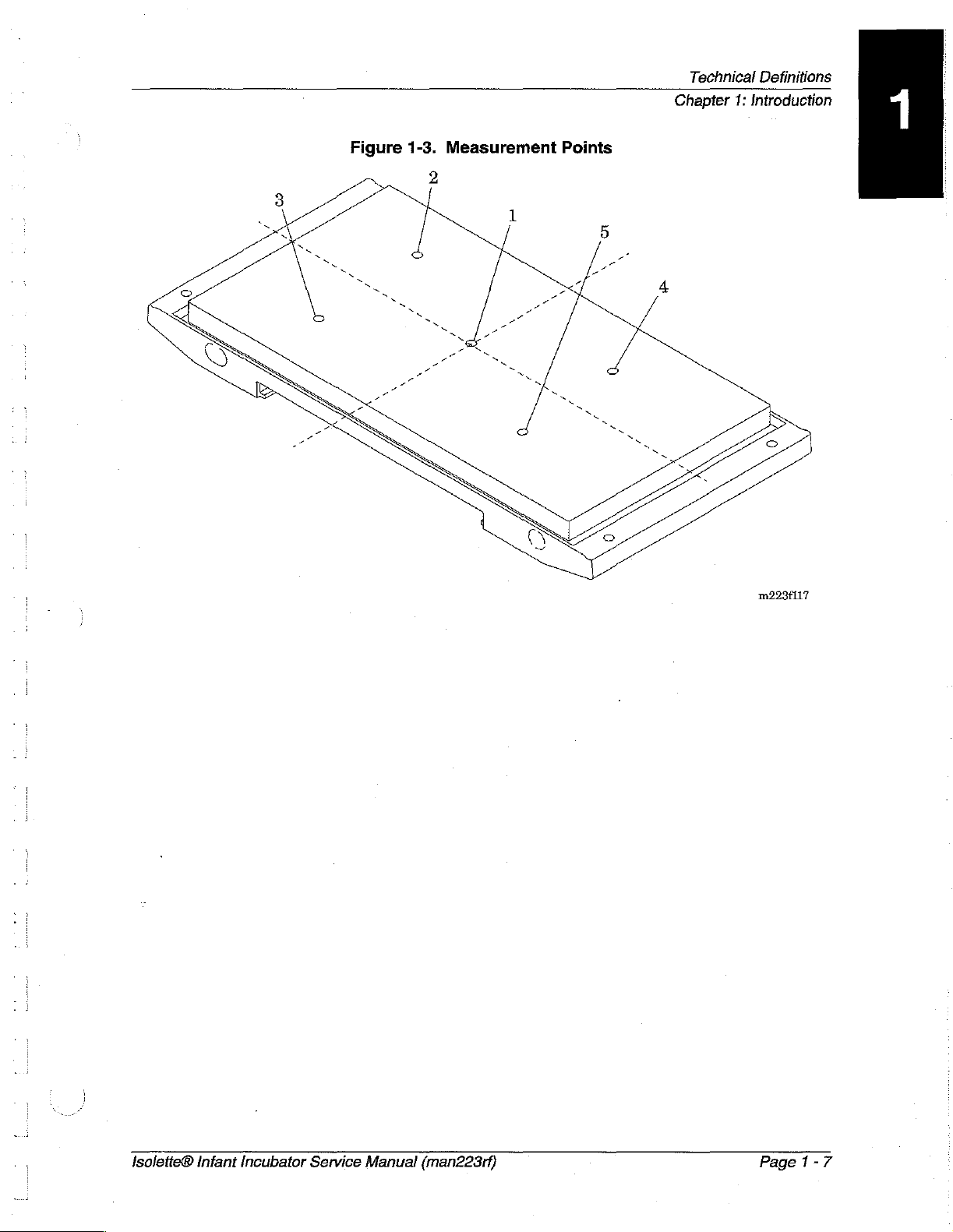
Measurement
parallel
page
1-7).
remaining
divide
as a result
temperature
of
an
increase
equilibrium
temperature
to
and
One
four
both
the
correlation:
correlation:
points-—Measurements
4"
point
points
width
incubator
temperature
of an
equilibrium
in
control
Incubator
amount
differs
Temperature
amount
equilibrium
(10
cm)
above
is
4"
(10
are
the
and
length
amount
increase
in
temperature
the
air
temperature
from
the
the
air
temperature
differs
the
mattress
cm)
above
centers
into
of
two
by
which
at
incubator
control
shall
incubator
temperature.
be
restored within
value.
temperature
indicator
control
temperature.
indicator
indicator
from
the
are
taken
at
surface
the
center
four
areas
parts.
temperature
temperature
Additionally,
versus
versus
control
five
(see
of the
formed
control
at
incubator
control
in
air
temperature.
points
figure
mattress;
by
lines
15
min
as
mode
at
in a plane
1-5
on
the
that
a
Page
1-6
Isolette®
Infant
Incubator
Service
Manual
(man2283rf)
Technical
Chapter
Definitions
1:
Introduction
Figure
1-3.
Measurement
Points
m223f117
Isolette®
Infant
Incubator
Service
Manual
(man223rf)
Page
1-7
Introduction
Chapter
1:
Introduction
Introduction
Overview
On
the
Isolette®
a
front
panel
temperature, a Trend
heater
Optional
also
power
Trend
available. A comprehensive
Infant
key.
Instrumentation
display
with
user-selectable
displays
Incubator,
skin
includes
of
two
intervals
of
oxygen
concentration,
visual
or
air
temperature
digital
skin
temperatures,
of
and
audible
displays
2,
4,
weight,
air
8,
12,
alarm
control
temperature,
and
and
system
for
air
24
humidity
is
selected
and
hours.
is
by
skin
and
are
provided.
Operating
For
additional
accessories,
Features
Oval
Dual
Mattress
A
mattress
12°
from
Pedestai Stand
The
pedestal
variable
Oxygen
Precautions
operating
refer
to
Access
access
height
Doors
doors
Tilt
Mechanism
tilt
mechanism
either
end.
stand
adjustable.
Control
are
Assembly
assembly
System
precautions
the
Isolette®
provided
is
for
the
Infant
Incubator
with a quiet
provided,
is
available
and
(Optional)
Isolette®
latch.
is
continuously
in
two
models:
Infant
User
Incubator
Manual.
variable
fixed
height
.
and
from
and
its
0°
to
Page
1-8
The
oxygen
level
within
Humidity
The
humidity
incubator
control
the
incubator
System
system
hood
environment.
system
monitors
hood
(Optional)
monitors
and
Isolette®
and
controls
environment.
controls
Infant
the
Incubator
the
oxygen
humidity
Service
concentration
level
within
Manual
the
(man223rf)

Chapter
Introduction
1:
Introduction
Weighing
A
weighing
infant.
Platform
platform
(Optional)
located
under
the
mattress
measures
the
weight
of
the
Isoletie®
Infant
Incubator
Service
Manual
(man223rf)
Page
1-9
Specifications
Chapier
1:
Introduction
a
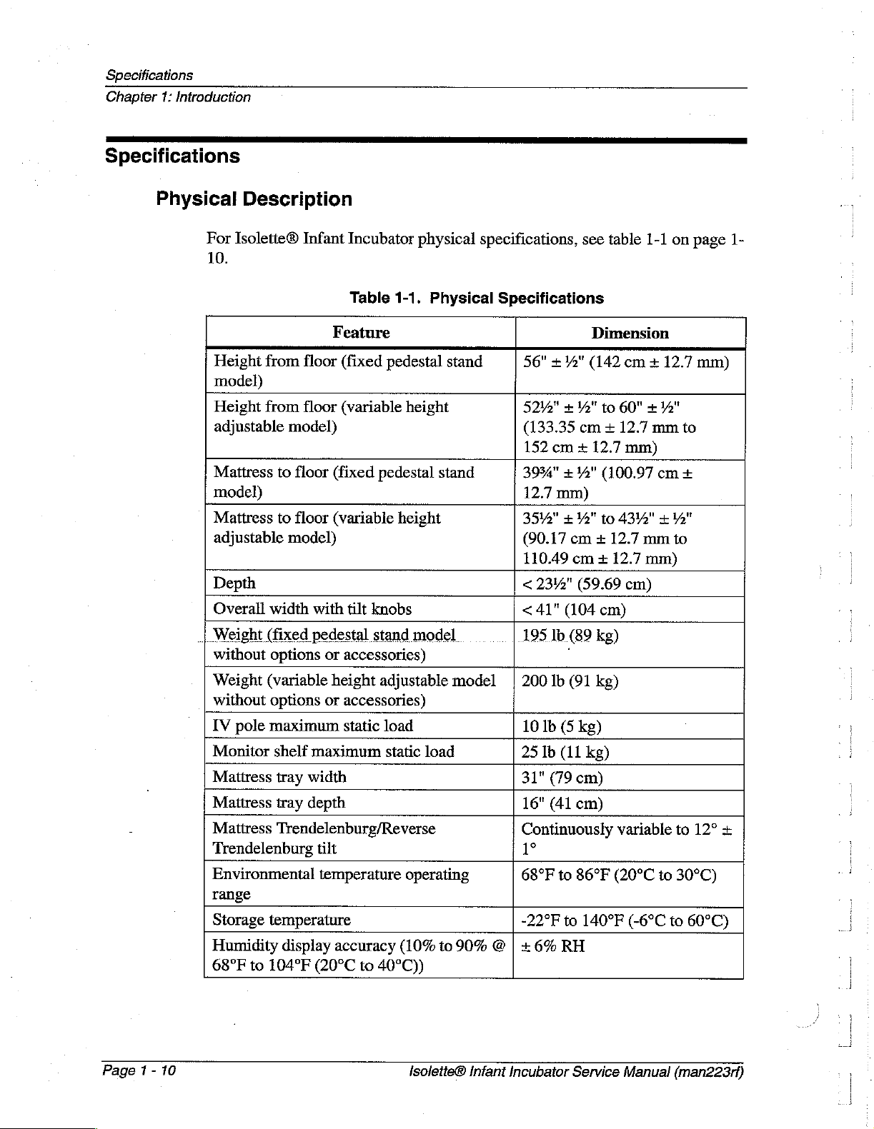
Specifications
Physical
Description
For
Isolette®
10.
Height
model)
Height
adjustable
Mattress
model)
Mattress
adjustable
Depth
Overall
+
Weight
without
Weight
without
IV
pole
Monitor
Mattress
Mattress
Mattress
Trendelenburg
Environmental
range
Storage
Humidity
68°F
Infant
from
floor
from
floor
model)
to
floor
to
floor
model)
width
(fixed
options
(variable
options
maximum
shelf
tray
tray
Trendelenburg/Reverse
temperature
display
to
104°F
Incubator
Table
Feature
(fixed
(variable
(fixed
(variable
with
pedestal
or
height
or
maximum
width
depth
tilt
temperature
accuracy
(20°C
pedestal
tilt
knobs
stand
accessories)
adjustable
accessories)
static
to
40°C))
load
physical
1-1.
Physical
pedestal
height
height
model
static
load
operating
(10%
specifications,
Specifications
stand
stand
model |
to
90% © | + 6%
see table
Dimension
56"
+72"
(142
5242" + Ya"
(133.35
152
cm + 12.7
3934"
12.7
mm)
3542" + 4"
(90.17
110.49
<
23%"
<
41"
195
1b
200
lb
10
lb (5
25
lb
31"
(79
16"
(41
Continuously
1°
68°F
to
-22°F
to
cm + 12.7
+12"
(100.97
to
cm + 12.7
cm + 12.7
(59.69
(104
cm)
(89
kg)
(91
kg)
kg)
(11
kg)
cm)
cm)
86°F
to
140°F
RH
1-1
cm + 12.7
60" x W"
mm
mm)
cm
4342" + 12"
mm
mm)
cm)
variable
(20°C
to
(-6°C
on
page
mm)
to
+
to
to
12°
30°C)
to
60°C)
|
1-
+
Page 1 -
10
Isolette®
Infant
Incubator
Service
Manual
(man223rf)
Chapter
Specifications
1:
Introduction
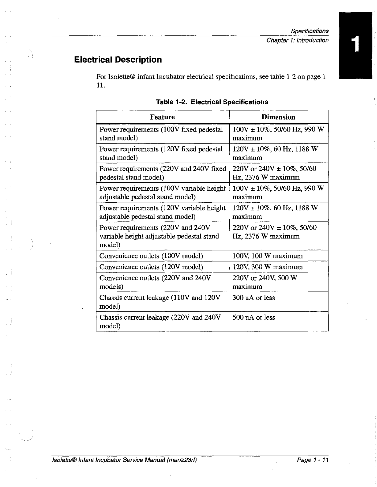
Electrical
For
Isolette®
11.
Power
stand
Power
stand
Power
pedestal
Power
adjustable
Power
adjustable
Power
variable
model)
Convenience
Convenience
Convenience
models)
Chassis
model)
Chassis
model)
Description
Infant
requirements
model)
requirements
model)
requirements
stand
requirements
pedestal
requirements
pedestal
requirements
height
current
current
Incubator
Table
Feature
model)
stand
stand
adjustable
outlets
outlets
outlets
leakage
leakage
1-2.
(100V
(120V
(220V
(100V
model)
(120V
model)
(220V
(100V
(120V
(220V
(110V
(220V
electrical
Electrical
fixed
pedestal
fixed
pedestal
and
240V
variable
variable
and
240V
pedestal
model)
model)
and
stand
240V
and
120V | 300
and
240V | 500
specifications,
Specifications
100V + 10%,
maximum
120V + 10%,
maximum
fixed
height
height
220V
Hz,
2376 W maximum
100V + 10%,
maximum
120V + 10%,
maximum
220V
Hz,
2376 W maximum
100V,
120V,
220V
maximum
uA
uA
see
table
1-2
Dimension
50/60
Hz,
60
Hz,
or
240V + 10%,
50/60
60
or
240V + 10%,
100 W maximum
300 W maximum
or
240V,
or
less
or
less
Hz,
500
Hz,
W
on
page
990
1188
50/60
990
1188
50/60
1-
W
W
W
W
Isolette®
Infant
Incubator
Service
Manual
(man223rf)
Page
1-11
Specifications
Chapter
1:
Introduction
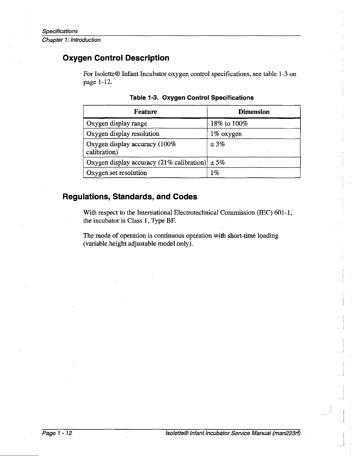
Oxygen
Control
For
Isolette®
page
1-12.
Oxygen
Oxygen
Oxygen
calibration)
Oxygen
Oxygen
display
display
display
display
set
Regulations,
With
respect
the
incubator
Description
Infant
resolution
Incubator
Table
1-3.
Feature
range
resolution
accuracy
accuracy
Standards,
to
the
International
is
Class
1,
Type
oxygen
Oxygen
(100%
(21%
and
BF.
control
Control
calibration); + 5%
specifications,
Specifications
18%
1%
+
3%
1%
Codes
Electrotechnical
Dimension
to
100%
oxygen
Commission
see
(IEC)
table
601-1,
1-3
on
The
mode
(variable
height
of
operation
adjustable
is
continuous
model
operation
only).
with
short-time
loading
Page
1-12
Isolette®
Infant
Incubator
Service
Manual
(man223rf)
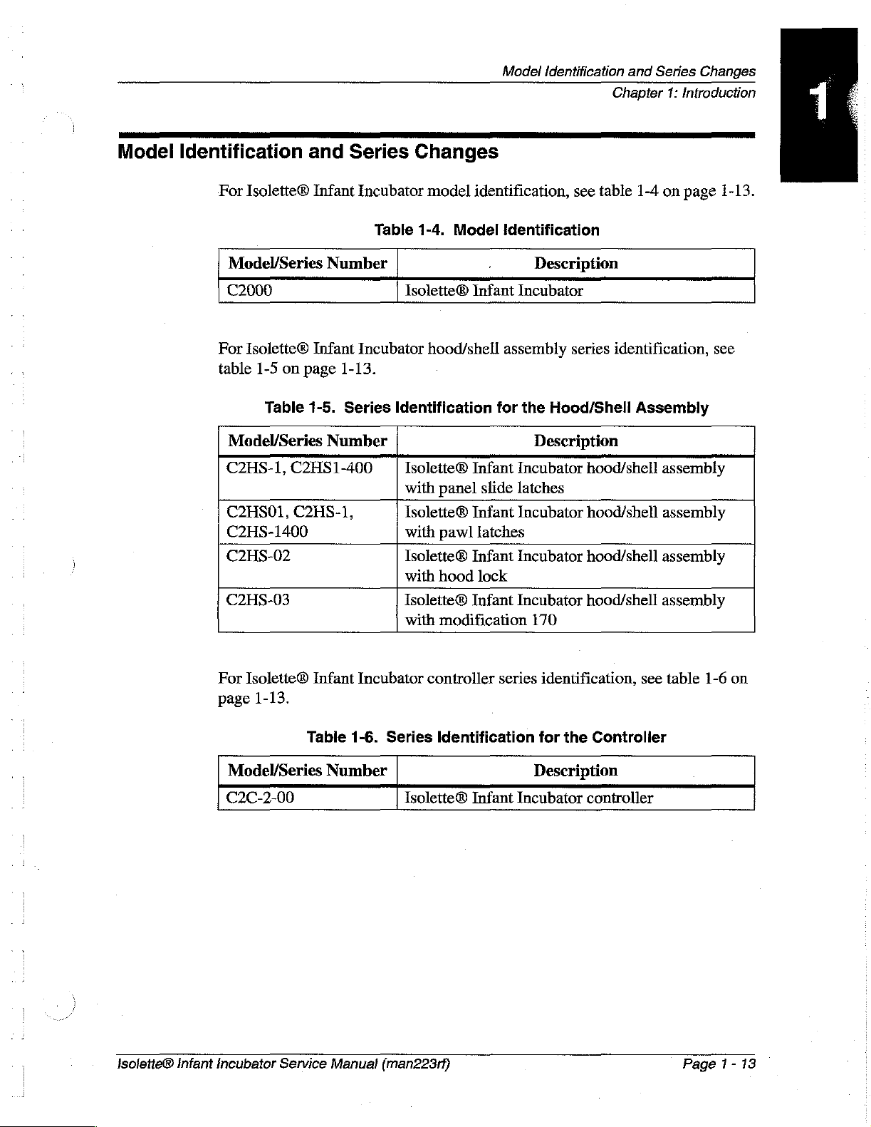
Model
Identification
For
Isolette®
and
Infant
Series
Incubator
Changes
model
identification,
Model
Identification
see
and
Chapter
table
Series
1-4
Changes
1:
Introduction
on
page
1-13.
Model/Series
C2000
For
Isolette®
table
1-5
on
page
Table
Model/Series
C2HS-1,
C2HS01,
C2HS-1400
C2HS-02
C2HS-03
C2HS1-400
C2HS-1,
Number
Infant
1-13.
1-5.
Series
Number
Table
Incubator
1-4.
Isolette®
Identification
Isolette®
with
Isolette®
with
Isolette®
with
Isolette®
with
Model
Identification
.
Infant
hood/shell
panel
pawl
hood
modification
assembly
for
Infant
slide
Infant
latches
Infant
lock
Infant
Description
Incubator
series
the
Hood/Shell
Description
Incubator
hood/shell
latches
Incubator
Incubator
Incubator
170
hood/shell
hood/shell
hood/shell
identification,
Assembly
assembly
assembly
assembly
assembly
see
Isolette®
Infant
For
Isolette®
page
1-13.
Model/Series
C2C-2-00
Incubator
Service
Infant
Table
Number
Manual
Incubator
1-6.
Series
Isolette®
(man223rf)
controller
Identification
series
Infant
identification,
for
the
Controller
Description
Incubator
controller
see
table
Page 1 -
1-6
on
13
Model
Identification
Chapter
1:
Introduction
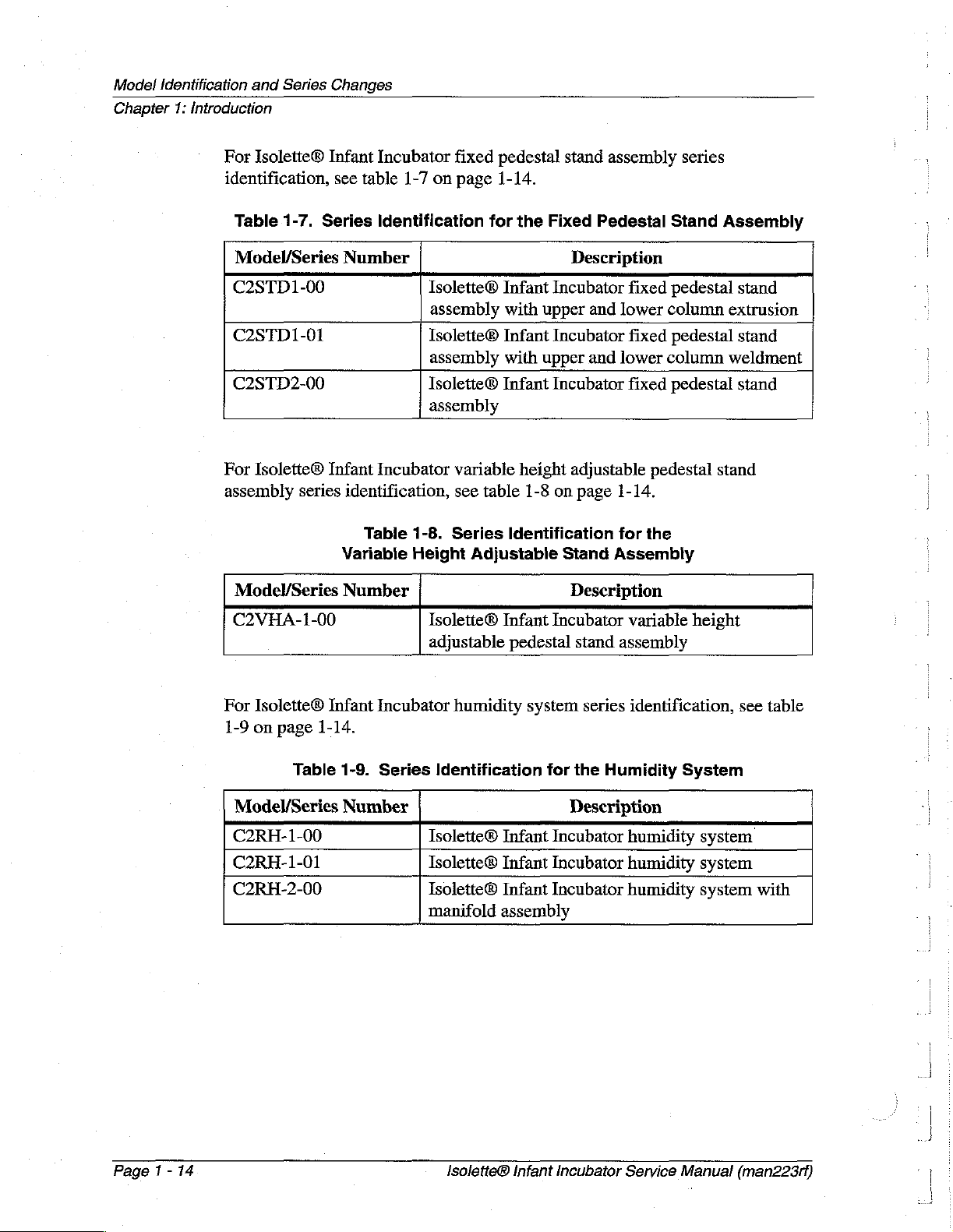
For
identification,
and
Series
Isolette®
Changes
Infant
see
table
Incubator
1-7
on
fixed
page
pedestal
1-14.
stand
assembly
series
Table
Model/Series
C2STD1-00
C2STD1-01
C2STD2-00
For
assembly
Model/Series
C2VHA-1-00
1-7.
Isolette®
series
Series
identification
Number
Infant
Incubator
identification,
Tabie
Variable
Number
1-8.
Height
for
Isolette®
assembly
Isolette®
assembly
Isolette®
assembly
variable
see
Series
Isolette®
adjustable
Infant
with
Infant
with
Infant
table
Identification
Adjustable
Infant
pedestal
the
Fixed
Incubator
upper
Incubator
upper
Incubator
height
1-8
on
Incubator
Pedestal
Description
fixed
and
lower
fixed
and
lower
fixed
adjustable
page
1-14.
for
Stand
Assembly
Description
variable
stand
assembly
Stand
pedestal
column
pedestal
column
pedestal
pedestal
the
height
Assembly
stand
extrusion
stand
weldment
stand
stand
Page
1-14
For
Isolette®
1-9
on
page
Table
Model/Series
C2RH-1-00
C2RH-1-01
C2RH-2-00
Infant
1-14.
1-9.
Number
Incubator
Series
Identification
Isolette®
Isolette®
Isolette®
manifold
Isolette®
humidity
Infant
Infant
Infant
assembly
Infant
system
series
for
the
Description
Incubator
Incubator
Incubator
Incubator
identification,
Humidity
humidity
humidity
humidity
Service
System
system
system
system
Manual
see
table
with
(man223rf)

Safety
Tips
Chapter
Safety
1:
Introduction
Tips
A
A
WARNING:
Only
facility-authorized
Infant
result
Incubator.
in
personal
WARNING:
To
prevent
stand
adequately
when
injury
transporting,
control
WARNING:
Do
not
use
the
incubator
qualified
equipment
personnel.
damage.
WARNING:
A
dirty
air
intake
cause
change
carbon
at
least
dioxide
personnel
Troubleshooting
injury
or
or
damage
equipment
to
the
employ a person
the
incubator.
if it
fails
Failure
microfilter
every 3 months.
to
do
may
build-up.
Check
should
by
unauthorized
damage.
variable
to
function
so
could
affect
oxygen
the
troubleshoot
the
personnel
height
of
properly.
result
adjustable
sufficient
Refer
in
personal
concentrations
filter
on a routine basis
Isolette®
could
pedestal
strength
service
injury
and/or
to
to
or
and
Isolette®
WARNING:
The
procedure.
WARNING:
sound
WARNING:
Infant
Incubator
heater
heater
If
the
Heater
probe.
Follow
result
in
radiator
radiator
to
cool
Failed
within 5 min,
Failure
the
personal
Service
to
do
product
injury
Manual
manufacturer’s
can
be
for
at
message
turn
off
so
can
or
equipment
(man223rf}
sufficiently
least
does
the
power
result
20
min
not
in
damage
hot
appear
switch,
instructions.
damage.
to
cause
before
and
and
to
the
Failure
burns.
Permit
attempting
the
alarm
replace
the
incubator.
to
do
'
this
does
airflow
so
could
Page
the
not
1-15

Safety
Chapter
Tips
1:
Introduction
A
A
WARNING:
Make
the
cleaning
in
sure
that
the
incubator
is
procedures. A fire
an
oxygen-enriched
WARNING:
A
dirty
inlet
filter
dioxide
commensurate
used
may
build-up.
in
an
unusually
be
necessary.
with
WARNING:
The
heater
touching
minutes.
can
the
heater
WARNING:
Only
facility-authorized
maintenance
performed
equipment
on
by
unauthorized
damage.
oxygen
supply
disconnected
and
environment.
may
affect
Be
sure
local
dusty
be
sufficiently
until
oxygen
the
conditions.
environment,
the
unit
personnel
the
Isolette©
personnel
to
from
the
explosion
concentration
filter
is
hot
to
has
should
infant
Incubator.
the
incubator
oxygen
supply
hazard
checked
Particularly,
cause
been
on a routine
more
frequent
burns.
switched
perform
Preventive
could
result
is
turned
exists
and/or
when
when
cause
off
performing
basis
if
the
incubator
replacements
Avoid
removing
off
for
at
preventive
maintenance
in
personal
and
that
cleaning
carbon
is
or
least
45
injury
or
Page
1-16
WARNING:
The
administration
within
the
incubator.
WARNING:
Make
the
sure
that
incubator
maintenance
performing
maintenance
environment.
of
oxygen
the
oxygen
is
disconnected
procedures. A fire
may
supply
from
and
procedures
{solette®
increase
to
the
incubator
the
oxygen
explosion
in
an
Infant
Incubator
the
noise
supply
hazard
level
is
turned
when
exists
for
oxygen-enriched
Service
Manual
the
baby
off
and
that
performing
when
(man223rf)

Chapter
Safety
1:
Introduction
Tips
A
A
A
AN
WARNING:
The
incubator
provided.
the
pedestal
must
Failure
siand
WARNING:
To
keep
the
incubator
pedestai/stand
and
locked.
front
WARNING:
Oxygen
concentration
continuously
so
SHOCK
Make
electrical
variable
reliability,
hospital-grade
could
sure
flow
rates
in
monitored
result
in
HAZARD:
that
specifications
height
connect
or
be
attached
to
do
so
could
if
sufficiently
from
locking
cannot
an
incubator.
be
with a calibrated
personal
the
building
shown
adjustable
the
pedestal
power
hospital-use
to
the
result
tilted,
sliding
when
casters
used
as
Oxygen
injury
or
power
on
source
the
stand.
cord
only
receptacle.
pedestal
in
the
stand
incubator
particularly
parked
must
be
facing
an
accurate
concentrations
oxygen
equipment
right
damage.
is
compatible
side
of
For
proper
to a properly
Do
not
using
separating
with
the
on an
incline,
down
the
indication
must
analyzer.
with
the
incubator
grounding
marked
use
extension
the
bolts
from
hood
open.
the
incline
of
oxygen
be
Failure
to
the
and
three-wire
cords.
do
the
AN
A
Isolette©
SHOCK
Unplug
personal
个
SHOCK
Do
equipment
CAUTION:
When
the
stability.
infant
Incubator
HAZARD:
the
unit
injury
HAZARD:
not
expose
damage
using
the
incubator
Service
from
or
equipment
the
unit
variable
to
its
lowest
Manual
its
power
to
excessive
could
occur.
height
position
(man223rf)
source.
damage.
moisture.
adjustable
prior
Failure
to
Personal
pedestal
to
transport
do
so
stand,
for
could
result
injury
or
always
optimum
Page
in
lower
1-17

Safety
Chapter
Tips
1:
Introduction
A
A
CAUTION:
When
module
and
reconnecting
cable
not
the
CAUTION:
Replace
could
CAUTION:
Do
could
CAUTION:
Some
residue
conductive.
components.
surfaces.
both
result
not
use
occur.
chemical
that
harsh
the
rear
connector
RS-232
oxygen
in
equipment
connector.
sensor
cleaners,
cleaning
may
permit a build-up
Do
not
permit
Do
not
spray
panel
is
connected
cells
damage.
solvents,
agents
cleaning
cleaning
connectors,
to
the
at
the
same
or
detergents.
may
be
conductive
of
dust
agents
solutions
sensor
or
dirt,
to
contact
onto
make
module
|
time.
Equipment
and/or
which
any
sure
the
sensor
connector,
Failure
to
do
damage
leave
may
be
electrical
of
these
so
a
CAUTION:
When
prevent
cleaning
liquids
damage
CAUTION:
Alcohol
for
can
cleaning.
CAUTION:
Do
not
expose
lamps.
Ultraviolet
gaskets,
from
could
occur.
cause
fading
the
interior
entering
crazing
the
hood
radiation
of
paint,
of
the
the
of
the
assembly
from
these
and
crazing
incubator
motor
clear
to
direct
shaft
acrylic
sources
of
the
shell,
care
opening.
hood.
Do
radiation
can
cause
clear
acrylic
must
be
Equipment
not
use
from
germicidal
cracking
hood.
taken
to
alcohol
of
Page
1-18
Isolette®
Infant
Incubator
Service
Manual
(man223rf)

Chapter
Safety
1:
Introduction
Tips
A
CAUTION:
Failure
sufficient
control
CAUTION:
>
Before
accessories
the
raised
CAUTION:
>
To
prevent
only
handle
CAUTION:
When
to
handling
do
so
to
clean
lint
build-up
and
cause
lifting
the
have
hood.
component
the
could
result
the
heater
to
reduce
high
oxygen
incubator
been
removed
damage,
P.C.
board
electronic
components,
in
component
radiator
hood
and
airflow,
concentrations.
for
cleaning,
to
prevent
ensure
by
its
edges.
damage.
fan
impeller
which
that
wear
could
will
affect
ensure
possible
your
hands
an
antistatic
result
temperature
that
all
interference
are
strap.
in
mounted
with
clean,
Failure
and
CAUTION:
For
shipping
protective
CAUTION:
> > >
Do
not
and
storage,
bag.
Equipment
use
silicone-based
place
the
removed
damage
lubricants.
can
Equipment
P.C.
occur.
board
damage
in
an
antistatic
could
occur.
Isolette®
Infant
Incubator
Service
Manual
(man223rf)
Page
1-19

Warning
Chapter
and
1:
Warning
Caution
Labels
Introduction
and
Caution
Labels
Figure
X
OXYGEN
OXYGEN
OXYGEN
OXYGEN
CONCENTRATIONS
MUST
BE
CONTINUOUSLY
WARNING:
+
IMPROPER
SIDE
EFFECTS.
PERSONNEL
*
THE
OXYGEN
DETERMINE
SHOULD
THE
ATTENDING
°
FIRE
HAZARD - KEEP
iN
WHICH
BUAN
WITH
+
USE
OF
ANESTHETIC
CONCENTRATION
SUPPLY
3
LPM
6
LPM
9
LPM
12
LPM
15
LPM
ALLOW
OXYGEN
FLOW
RATES
CAN
USE
OF
SUPPLEMENTAL
OXYGEN
UNDER
THE
CONCENTRATION
THE
PARTIAL
BE
MEASURED
PHYSICIAN.
MATCHES
OXYGEN
18
JN
GREAT
INTENSITY
AGENTS
CONCENTRATIONS
WARNING:
NOT
IN
AN
MONITORED
INLET
1
SHOULD
DIRECTION
PRESSURE
BY
AN
ACCEPTED
AND
USE.
COMBUSTIBLE
IN
CAN
DANGER:EXPLOSION
‘THE
PRESENCE
Y
1-4.
APPROX.
3045
40-60
45-75
50-85
6090
TO
BE
USED
AS AN
INCUBATOR.
4
ONLY
INSPIRED
OXYGEN
ACCURATE
OXYGEN
WITH A CALIBRATED
OXYGEN
MAY
BE
ADMINISTERED
OF A QUALIFIED
BY AN
OF
OXYGEN
GLINICAL
OTHER
SOURCES
MATERIALS
ENRICHED
INTERFERE
WITH
HAZARD
OF
FLAMMABLE ANESTHETICS
Warning
GUIDE
OXYGEN
%
STABILIZE
INDICATION
CONCENTRATIONS
OXYGEN
BE
ASSOCIATED
SY
ATTENDING
INFANT
DOES
(p02)
IN
THE
TECHNIQUE
OF
IGNITION
ARE
AIR.
OXYGEN
DO
NOT
USE
Itt
OF
ANALYZER
WITH
SERIOUS
PROPERLY
PHYSICIAN.
NOT
ACCURATELY
BLOOD.
THE
WHEN
ADVISED
OUT
OF
EASILY
IGNITED
ANALYZER
ACCURACY.
and
TRAINED
202
BY
ROOM
AND
Caution
IMPORTANT:
INSPECT
AIR
DURING
CLEANING
REPLACE
IF
NECESSARY
A
IMPORTANT:
DO
NOT
TO
INLET 1 AND
SIMULTANEOUSLY.
OXYGEN
MAX.
PRESSURE
(10.55
MİN.
Labels
FILTER
APPLY
OXYGEN
CONTROLLER
150 PSI
Kolena)
FLOW:
30
LEM
INLET
2
INLET
2
Page
1-20
-
CAUTION
-
MAXIMUM 2 LBS
WEIGHT
-
CAUTION
(91
Kg)
-
MAXIMUM 5 LBS
WEIGHT
-
CAUTION
MAXIMUM
WEIGHT
(2.2
Kg)
-
10
LBS
(4.5
Kg)
{solette®
Infant
Incubator
Service
Manual
m2231091
(man223rf)

Chapter
2
Troubleshooting
Chapter
Getting
Initial
FuncüonChecks....................
nalActlong
Alarms
System
Diagnostic
Contents
Started し し
Actions
High
and
Alarm
Entering
Messages
Failure
Menus
よー
..
Low
Air
and
Skin
...............................................
Messages
.................................................
the
Diagnostic
...........................................
Menus.
Procedures
cee
0...
keen
Temperature
...................................
Alarms
rr
skeerne
.....................
rro
aramaz
kr
skne
2-3
2-3
2-4
2-14
2-15
2-15
2-
16
2-24
2-25
2-25
Diagnostic
System
KeyCheckbDisplay.....................
Data
Variable
Low
Set
Oxygen
Oxygen
Concentration
Concentration
Information
Test
Menu
Summary
Height
Temperature
Menu
Adjustable
Menu.
...................,............,.,...........
...............................,...........
Alarm
is
Low
is
High
....................................
Pedestal/Stand
Activated.....................
.......................................
.......................................
Will
0...
Not
Move
νε
Up
κών
ων
or
Down...
eee
κε ο ον ον
....
2-27
2 - 28
2-31
2-32
2-34
2-36
2-38
2-41
Isolette®.Infant
Incubator
Service
Manual
(man223rf)
Page
2-1

Chapter
NOTES:
2:
Troubleshooting
Procedures
Page
2-2
Isolette®
Infant
Incubator
Service
Manual
(man223rf)

Getting
Started
Chapter
2:
Troubleshooting
Getting
Procedures
Started
A
WARNING:
Only
facility-authorized
Infant
result
Begin
(each
normal
the
analysis
component
To
To
corrective
perform
To
If
Technical
incubator.
in
personal
each
procedure
step
assumes
operation
statement.
begin
isolate
verify
troubleshooting
Your
procedure
is
listed,
gathering
or
identify a problem
action
the
the
(replacing
Function
repair,
Support
personnel
Troubleshooting
injury
the
of
response
(RAP),
information
procedures
at
or
in
this
previous
the
product
or a component
replace
Checks.
perform
(800)
445-3720
equipment
chapter
step
can
will
lead
them
in
about
and
or
adjusting a part,
the
Final
do
not
should
by
troubleshoot
unauthorized
damage.
with
step
has
been
completed).
be
confirmed
to
another
replacement.
the
given
order.
the
problem,
to
verify
Actions
isolate
for
the
the
assistance.
the
|solette®
personnel
1.
Follow
step
repair
seating a connector,
after
probiem,
the
by
answering
in
the
İf
start
with
after
the
Function
sequence
In
each
Yes
procedure, a repair
more
than
Initial
completing
call
Hill-Rom
could
outlined
step,
the
or
No
one
Actions.
each
etc.),
Checks.
to
initial
Isolette
Actions
Infant
To
gather
Infant
information
Incubator,
concerning
identify
1.
the
Someone
Yes
No
y
2.
Ask
that
duplicated.
Yes
3.
The
Incubator
No
y
problem
Service
use
the
problem
probable
who
can
>
Go
to
person
—
Goto
is a
Manual
from
operators
Initial
Actions.
that the
cause.
explain
“Function
to
demonstrate
“Function
result
of
(man223rf)
concerning
Note
operator
the
problem
Checks”
or
explain
Checks”
improper
symptoms
describes.
is
available.
on
page
the
problem.
on
page
operator
action.
problems
or
other
This
information
2-4.
2-4.
with
the
information
The
problem
Isolette®
helps
can
be
Page 2 -
3

Function
Chapter
Checks
2:
Troubleshooting
Procedures
Function
A
Yes
4.
Instruct
Incubator
y
No
—
the
Incubator,
Checks
Before
cleaning
WARNING:
Do
to
SHOCK
Make
electrical
variable
reliability,
the
incubator
or
maintenance,
not
use
the
qualified
personnel.
HAZARD:
sure
that
specifications
height
connect
hospital-grade
Go
to
“Function
operator
User
Manual.
perform
incubator
is
the
building
the
first
adjustable
the
or
hospital-use
Checks”
to
refer
to
To
ensure
“Function
placed
perform
if
it
fails
power
shown
pedestal
power
cord
on
page
the
procedures
proper
Checks”
into
Function
to
function
source
on
the
stand.
only
receptacle.
operation
on
service,
Checks.
is
right
For
to a properly
Do
2-4.
in
the
Isolette®
of
page
2-4.
and
after
as
described.
compatible
side
of
the
proper
marked,
not
use
Infant
the
Isolette®
any
disassembly
Refer
with
the
incubator
grounding
three-wire,
extension
Infant
for
service
and
the
cords.
Page
2-4
WARNING:
To
prevent
stand
when
adequately
CAUTION:
When
the
using
incubator
stability.
1.
Initial
Yes
2.
Connect
a.
{$
Connect
Actions
No
>
injury
or
damage
transporting,
contro]
the
the
the
variable
to
its
lowest
have been
Goto
“Initial
pedestal
the
pedestal
incubator.
height
stand
to
the
variable
employ a person
adjustable
position
performed.
Actions”
AC
stand
Isolette®
prior
on
power
power
Infant
to
page
cord,
cord
Incubator
height
of
pedestal
transport
adjustable
sufficient
stand,
for
2-3.
and
apply
to
an
AC
source.
Service
strength
always
optimum
power:
Manual
pedestal
to
lower
(man223rf)

3.
b.
Press
c.
Press
unit
All
indicator
Yes
y
Check
cord
from
Power
Yes
y
the
the
Power
Power
switch
switch
performs a self-test
No
—
the
Fail
No
—
If
of the
Module
Power
its
There
The
lamps
the
on
power
indicator
light,
unit
following
Display
Failure.
Failure
source.
is
no
Power
and
fails
#1:
alarm
on
the
power,
switch
on
the
pedestal
on
the
incubator.
indicated
the
audible
the
self-test,
messages
Controller
Refer
the
by
unplugging
The
Power
controller
and
the
is
not
on.
Chapter
by
the
appear
Fail,
unit
Failure
lights.
Power
Press
stand.
When
the
flashing
alarm
alarm
in
EEPROM
to
service.
Failure
the
2:
Troubleshooting
initially
is
pulsed.
sounds,
place
the
pedestal
alarm
alarm
Power
Function
turned
hourglass.
and
of
the
Trend
Fail,
or
stand
sounds,
is
not
switch.
Checks
Procedures
on, the
one
or
more
display
Sensor
power
and
the
activated.
4.
5.
Perform
a.
Connect
into
b.
After
95°F
Check
the
Turn
b.
Use
pedestal
maximum
the
following:
the
the
wall
the
self-test,
(35°C).
variable
on
the
your
foot
stand,
height
power
stand
Allow
height
main
to
press
front,
cord.
and
incubator
Display
the
adjustable
power
the
up/down
(see
figure
Make
#1
appears.
unit
to
switch.
Up
arrow
switch
2-1
sure
the
power
receptacles.
Set
the
operate
while
pedestal/stand
of
the
variable
(X)
to
raise
on
page
2-6).
cord
is
air
set
temperature
checking
if
so
equipped.
height
the
stand
fully
plugged
the
hood/shell.
adjustable
to
to
the
Isolette®
infant
Incubator
Service
Manual
(man223rf)
Page 2 -
5

Function
Chapter
Checks
2:
Troubleshooting
Procedures
Figure
2-1.
Variable
Height
Adjustable
Pedestal/Stand
Up/Down
Switch
112234072
6.
c.
„Press
pedestal
height.
d.
Repeat
The
stand
Yes
No
L © >
Check
a.
b.
d.
e.
The
Yes
the
Disconnect
Slowly
Close
e
Connect
Connect
hood
No
|
and
hold
stand
using
the
operates
GotoRAP22.
hood
(A)
the
tilt
the
the
hood
the
cables
the
weighing
operates
—
Replace
the
Down
up/down
rear
switch
up/down
smoothly
operation
weighing
hood
(A)
back
(A).
on
the
scale
correctly.
the
hood.
arrow
and
adjusts
(see
scale
cable
until
sensor
cable
of
the
(X)
to
switch
to
figure
(B)
the
module
(B)
variable
lower
the
(X).
the
desired
2-2
on
page
from
hood
(A)
(C).
on
the
sensor
height
stand
height.
2-7).
the
sensor
comes
module
adjustable
to
the
minimum
module
to
rest.
(C).
(C).
一
o
i
Page
2-6
Isolette®
Infant
Incubator
Service
Manual
(man228rf)
13

Chapter
2:
Troubleshooting
Function
Checks
Procedures
Figure
2-2.
Hood/Shell
Assembly
Operation
Isolette®
Infant
Incubator
Service
Manual
(man223rf)
m223f038
'
Page2-7

Function
Chapter
Checks
2:
Troubleshooting
7.
For
following:
a.
b.
c.
d.
The
Yes
y
Procedures
hoods
Disconnect
Slowly
Release
the
Connect
(A)
tilt
the
right
equipped
the
the
hood
rear
the
self-locking
No
>
Replace
with a self-locking
weighing
hood
(A)
(A) by
hinge
weighing
(E)
mechanism
the
self-locking
scale
back
pulling
while
scale
cable
and
cable
until the
on
and
closing
(B)
knob
(D)
mechanism
mechanism,
(B)
from
hood
(A)
holding
the
hood
on
the
sensor
operate
and
perform
the
sensor
locks
in
the
knob
(D)
(A).
module
correctly.
knob
(D).
the
module
place.
located
(C).
(C).
on
Check
a.
the
Ona
panel
b.
On
all
open
c.
Pivot
down).
d.
Check
e.
Close
The
latches
panel(s)
Yes
Check
The
Yes
L
+
No
—
the
iris
No
—
(H)
access
“00”
Series
(F).
hoods
the
access
the
access
the
rear
the
access panel
(G)
(F).
Replace
iris
entry
opens
Replace
panel
hood,
other
panel
panel
access
are
properly
the
ports
and
the
(F).
slide
than
“00”
(F).
(F)
panel
(F).
access
(H) by
closes
iris
entry
the
blue
Series,
to
the
(F),
if
secured
panel
rotating
as
rotation
port
slide
rotate
full-open
so
to
(F)
(H)
position
equipped.
avoid
accidental
(refer
the
outer
is
continued
sleeve
latches,
the
paw!
to
procedure
ring
through
(refer
and
open
latches
(hanging
opening
4.7).
of the
to
iris
360°.
procedure
the
access
(G),
and
straight
of
the
port
(H).
4.8).
Page 2 -
8
10.
Check
a.
Press
swings
Yes
y
b.
Close
access
the
the
No
—
access
door
open.
Replace
the
doors
door
(1)
door
(I)
release
the
(I),
gaskets
latches
(J)
of
door
release
and
check
are
Isolette®
and
each
(J).
for
placed
infant
gaskets.
access door
proper
properly
latching
on
Incubator
(I).
The
and
the
inner and
Service
access
door
quietness.
outer
Manual
(man223rf)
(1)
The
walls.

Chapter
2:
Troubleshooting
Function
Checks
Procedures
11.
Yes
12.
knob
is
Yes
13.
Rotate
The
Yes
14.
Turn
the
Yes
Yes
y
Check
(F).
The
y
Check
at a 12°
y
mattress
y
the
mattress
y
No
—>
Replace
that
the
inner
front
and
rear
No
-5
Replace
the
mattress
(K)
counterclockwise
angle.
No
—
Replace
the
right
mattress
(L)
is
No
—>
Replace
left
mattress
(L)
is
at a 12°
No
>
Replace
the
access
walls
inner
the
inner
(L)
elevators.
the
mattress
tilt
level.
the
mattress
tilt
mechanism
the
mattress
door
(1)
are
properly
walls
are
wall.
Rotate
until
it
stops.
elevator.
mechanism
elevator.
angle.
elevator.
gasket.
latched.
properly
the
right
The
knob
knob
(K)
Open
the
latched.
mattress
right
end
of the
(K)
clockwise
clockwise.
access
tilt
mechanism
mattress
until
The
left
panel(s)
(L)
it
stops.
end
of
15.
Turn
mattress
Yes
y
16.
Check
b.
c.
The
Yes
17.
Check
the
left
(L)
No
—>
the
Slide
out
Carefully
supported
Return
mattress
No
小
—>
the
mattress
is
level.
Replace
mattress
the
mattress
lean
on
to
provide a firm
the
mattress
tray
(M)
Replace
air
intake
tilt
mechanism
the
mattress
tray
(M)
operation.
tray
(M)
the
mattress
infant
(L),
and
is a
firm
platform
the
mattress
microfilter
(N)
knob
elevator.
to
the
fully-extended
tray
(M)
platform.
close
the
for an
tray
(M).
(see
figure
(K)
counterclockwise.
to
make
sure
access
panel
(F).
infant.
2-3
on
page
The
position.
it
is
properly
2-10).
Isolette®
Infant
Incubator
Service
Manual
(man223rf)
Page
2-9

Function
Chapter
Checks
2:
Troubleshooting
Procedures
A
WARNING:
A
dirty
air
cause
at
carbon
least
every 3 months.
a.
Loosen
remove
b.
Inspect
The
microfilter
Yes
y
18.
Check
a.
Introduce a carefully
connector
b.
Using a calibrated
(A).
intake
dioxide
the
the
the
No
>
Replace
the
air/oxygen
microfilter
may
build-up.
two
thumbscrews
cover
microfilter
(Q).
(P).
(N) has no
the
microfilter
system.
measured 9 lpm
oxygen
(N).
affect
Check
(O)
visible
analyzer,
oxygen
the
on
dirt.
(N)
filter
the
air
(refer
to
of
oxygen
monitor
concentrations
routinely,
intake
procedure
the
filter
into
the
levels
and/or
and
change
cover
4.4).
oxygen
within
m223f039
(P),
input
the
hood
it
and
Page
2-10
{sofette®
Infant
Incubator
Service
Manual
(man223rf)

The
incubator
Yes
$
19.
Check
ray
Yes No
4
20.
If
installed,
a.
b.
c.
levels
tray
Pull
Check
Push
No
—
the
(R).
—
the
the
reach
(9
Ipm
Go
to
x-ray
tray
The
Replace
check
sensor
that
the
sensor
the
predicted
in
equals
RAP
(R).
x-ray
the
the
module
sensor
module
50%
2.4.
Open
tray
x-ray
sensor
lock
module
level
to
the
(R)
operates
tray
module
(S)
lock
as
70%)
access
(R).
down.
(C)
(S)
up.
Chapter
indicated
(see
panel
correctly.
lock
(S).
slides
in
2:
Troubleshooting
on
the
figure
(F),
and
2-2
and
out
Function
rear
panel
on
page
withdraw
of
the
hood
Checks
Procedures
(F)
of
the
2-7).
the
x-
(A).
When
Yes
21.
Check
warm
Yes
22.
When
remains
Yes
23.
Check
a.
b.
Yes
the
sensor
(C)
is
locked
No
y
Air
up
No
\
the
>
Replace
Mode.
to
>
Goto
Air
securely.
the
Temperature
within
No
4
—
GotoRAP
the
air
Set
Open
the
access
In
approximately 5 min,
Temperature
sounds.
No
y
>
Goto
module
the
sensor
With
all
air
set
temperature
RAP
2.1.
0.5°C
of
the
2.1.
Temperature
panel
message
RAP
2.1.
lock
(S)
module
access
display
set
(F).
the
appears
is
in
the
up
lock
(S).
openings
of
95°F
closed,
(35°C).
has stabilized,
temperature
alarm.
alarm
indicators
on
the
Trend
position,
allow
It
takes
the
for
15
min.
activates,
display,
the
sensor
the
incubator
less
digital
the
and
an
module
to
than 1 hour.
display
Low
Air
alarm
Isolette®
Infant
c.
Close
24.
Check
a.
Connect
Incubator
the
Skin
Service
access
Mode.
the
skin
Manual
panel
(F).
probe
(man223rf)
to
skin
connector
#1
on
the
sensor
module
Page
(C).
2-
11

Function
Chapter
Checks
2:
Troubleshooting
b.
c.
d.
In
Temperature
sounds.
Yes
ψ
NOTE:
The
sensor
second
sounds,
the
second
the
two
25.
Check
Procedures
Place
the
skin
probe
Set
the
skin
set
temperature
When
the
temperature
approximately 5 min,
No
—
module
skin
and
skin
Goto
probe
the
message
probe,
message
RAP
is
is
connected
appears
2.1.
equipped
Remove
first
temperatures.
the
Connect
Skin 1 Probe
4"
(10
cm)
to
stabilizes,
the
alarm
in
to
accept
to
the
Skin 2 Probe
select
Air
above
95°F
(35°C).
open
the
the
indicators
place
of the
two
skin
sensor
Mode,
module
and
alarm.
center
access
activate,
Trend
of
panel
the
display,
probes.
in
Skin
appears.
then
In
the
controller
the
mattress.
(F).
Low
Skin
and
However,
Mode,
order
to
the
alarm
when
the
an
alarm
connect
displays
a.
Remove
b.
Select
c.
Disconnect
sounds,
d.
The
e.
Press
Connect a skin
Yes
No
4
26.
Check
a.
the
Connect a skin
and a temperature
b.
Place
c.
Allow
d. If
the
The
incubator’s
the
Air
Yes
No
y
the
skin
Skin
Mode.
the
skin
and
the
message
the
Connect
Silence/Reset
probe.
—
Сою
ВАР
maximum
probe
the
skin
probe
the
incubator
Skin
Temperature
temperature
Temperature
>
Goto
RAP
probe
Skin
#2
probe
Temperature
Skin 1 Probe
key.
The
incubator
2.1.
air
temperature.
to
the
of
greater
sensor
to
heat.
display.
2.1.
from
#1
from
The
sensor
than
outside
alarm
stays
the
sensor
the
display
alarm
returns
module
99°F
the
sounds,
below
module
sensor
module
goes
appears.
goes
silent
to
normal
(C),
(37°C).
incubator.
press
the
103.8°F
(39.9°C)
(C).
(C).
The
blank.
for 5 min.
operation.
and
select
Skin
Silence/Reset
as
indicated
alarm
Mode
key.
by
Page 2 -
12
Isolette®
infant
Incubator
Service
Manual
(man223rf)

27.
Check
a.
Ensure
Reverse
b.
If
you
on
c.
If
necessary,
the
d.
Select
e.
Press
The
Weight
Yes
+
28.
Place a weight
weight
filled), a beep
Yes
y
the
weighing
that
the
mattress
system
Trendelenburg
desire a pounds/ounces
page
6-20.
Zero
softkey.
Display
the
Zero
display
No
—
Goto
is
displayed.
sounds
No
ー
Go
remove
RAP
of
known
to
RAP
any
2,
and
press
softkey
reads
2.1.
value
When
and
2.1.
accessory
(L)
is
(see
figure
display,
objects
the
twice
in
zero,
and
(less
the
Weight
the
weight
Chapter
(if
level,
2-2
from
Weigh
succession.
the
Weight
than
Sample
is
locked
2:
Troubleshooting
applicable).
i.e.,
not
in
Trendelenburg
on
page
2-7).
refer
to
“Installation
the
mattress
softkey.
Sample
15
Ib (7
kg)) on
bar
stops
into the
Function
(L)
before
bar
is
the
mattress.
searching
Weight
Checks
Procedures
or
and
Set-up”
pressing
searching.
The
(bar
display.
29.
Press
the
Home
30.
Yes
Remove
b.
display
y
check
a.
c.
d.
again
No
—
the
the
oxygen
Place a calibrated
the
mattress
On
Display
Turn
on
Set
the
Within 5 minutes,
+5%.
Yes
31.
Within 5 minutes,
+
y
5%.
No
—
key
to
displays
Goto
RAP
weight from
system
(L).
1,
press
Oxygen
oxygen
control.
setpoint
the
The
oxygen
the
return
the
to
value
Display
of
2.1.
the
mattress
accessory
oxygen
oxygen
oxygen
analyzer
the
Oxygen
to
45%.
analyzer
concentration
analyzer
2.
Press
the
weight
(L),
press
(if
applicable).
inside
softkey.
and
the
level
is
and
the
the
on
the
the
the
hood
Oxygen
too
low.
Oxygen
Weigh
mattress
Home
softkey,
(A)
at
display
Go
to
display
softkey.
The
(L).
and
the
center
reads
RAP
2.4.
reads
of
45%
45%
Isolette®
Infant
Incubator
Service
Manual
(man223rf)
Page 2 -
13

Final
Actions
Chapter
2:
Troubleshooting
Procedures
Final
32.
33.
Actions
1.
Yes
Check
a.
b.
d.
e.
y
Fill
the
Pre-warm
On
Turn
Within
No
->
The
the
humidity
the
reservoir,
hood
Display
on
30
50% + 6%.
Yes
Go
Complete
"Preventive
y
No
to
“Final
>
GotoRAP
the
oxygen
concentration
system
and
(A)
at
the
center
the
incubator
1,
press
the
the
humidity.
min
to
60
2.1.
Actions”
required
Maintenance
on
preventive
accessory
place
the
mattress
to
95°F
Humidity
Set
the
humidity
min,
the
hygrometer
page
2-14.
Checklist”
level
is
too
(if
applicable).
probe
of a calibrated
(L).
(35°C).
softkey.
setpoint
and
maintenance
on
page
6-8.
high.
Go
to
hygrometer
to
50%.
Humidity
procedures.
RAP
display
See
2,5.
inside
reads
|
| |
2.
Complete
all
required
administrative
tasks.
Page
2-14
Isolette®
infant
Incubator
Service
Manual
(man223r1)

Alarms
Chapter
2:
Troubleshooting
Alarms
Procedures
High
and
Low
The
high
and
temperature
*
Skin
temperature—+
*
Air
temperature
NOTE:
The
skin
temperature
and
Set-up”
A
temperature
Temperature
alarm,
the
Skin
and a high
The
alarm
alarm
skin
activation
15-min
remain
corrected
flashing
air
or
skin
Temperature
temperature
high
and
condition
indicators
temperature
of
audible
on
until the
within
Air
and
low
air
or
fluctuates
from
—1.59C,
limits
on
page
6-20.
below
or
Low
the
Skin
indicators,
set
temperature
in
the
low
air
or
is
corrected,
are
turned
alarms
other
audible
alarm
silence.
alarm
15
min,
Skin
Temperature
skin
temperature
the
set
1.0°C
-2.5°C
may
air
or
skin
Temperature
and a low
is
indicated
message
reading.
skin
temperature
the
alarm
off.
The
can
be
silenced
and
visual
When
condition
the
audible
alarms
temperature
also
be
set
set
temperature
in
the
temperature
by
center,
an
alarms
is
automatically
audible
by
alarms
the
alarm
is
corrected.
alarm
Alarms
are
actuated
as
follows:
to
+0.5°C.
message
reading. A temperature
High
audible
are
portion
pressing
are
not
is
If
is
activated.
Refer
is
indicated
center,
Air
Temperature
tone,
flashing
self-resetting;
silenced
of
the
high
the
Silence/Reset
affected
silenced,
the
the
alarm condition
if
the
skin
or
to
“Installation
by
Low
an
audible
above
or
High
indicators,
that
is,
and
the
visual
and
low
air
key;
by
use
of
the
alarm
indicators
is
air
Air
if
the
or
the
not
Isolette®
In
or
temperature
after
current
As a general
temperature,
the
Alternately,
operator
Silence
Infant
Incubator
addition,
low)
if
after
alarms
the
operator
temperature.
new
set
temperature
before
may
Mode.
Service
it
is
desired
the
incubator
raises
rule,
the
the
longer
changing
press
In
Procedural
Manual
to
change
is
in
operation,
are
automatically
or
lowers
greater
the
alarm
after
the
the
the
the
Silence/Reset
Silence
(man223rf)
the
air
silenced
the
air
change
remains
specified
current
air
key
Mode,
or
skin
the
high
for a specific
or
skin
set
from
the
silent.
to
time,
or
skin
place
the
If
the
low
set
temperature
temperature
amount
temperature
current
set
the
incubator
the
incubator
alarm
sounds.
temperature,
unit
in
Procedural
temperature
(either
and
low
from
fails
the
alarm
Page
of
the
time
to
reach
is
high
2-15

Alarms
Chapter
2:
Troubleshooting
Procedures
Alarm
silenced
Temperature,
for
up
to
Airflow,
Messages
The
alarm
oxygen
presented
2-20,
22.
In
the
other,
total
For
an
Power
Motor
EEPROM
Heater
Controller
through
and
system
and
humidity
in
table
table
2-4 on
event
that
the
messages
of
five
messages
explanation
Alarm
Failure
Failed
failed
failure 1 and
failure
14
two
15
min.
prompt
displays
2-1
on
page
or
that
can
of
system
2
1
Procedural
or
Probe
messages
during
page
2-16,
2-21,
table
more
alarms
describe
be
posted.
alarms,
Table
A
flashing
continuous
power
unplugged
alarm
Plug
source.
A
flashing
continuous
malfunction.
from
A
flashing
continuous
malfunction.
from
A
flashing
continuous
malfunction.
from
A
flashing
continuous
malfunction.
from
Silence
alarm
an
table
2-5
occur
the
alarms
refer
2-1.
System
to
the
for
15
the
power
service
service.
service.
service
Mode
occurs.
that
replace
alarm
on
alarm
audible
incubator
from
min,
alarm
audible
Turn
(refer
alarm
audible
Turn
alarm
audible
Turn
alarm
audible
Turn
(refer
condition
2-2
on
page
2-21,
simultaneously,
will
be
to
table
Alarms
Description
indicator
alarm
its
power
press
cord
into
indicator
alarm
the
to
indicator
alarm
the
indicator
alarm
the
indicator
alarm
the
to
is
terminated
the
Trend
page
2-18,
and
presented
2-1
on
appears
to
indicate
fails,
or
source.
the
Silence/Reset
an
appropriate
appears
to
indicate a motor
incubator
procedure
appears
to
indicate
incubator
appears
to
indicate a heater
incubator
appears
to
indicate
incubator
procedure
Display
or
procedure
table
table
2-6
or
one
in
page
2-16.
with
the
power
To
with
off,
and
4.6).
with
off,
and
with
off,
and
with
off,
and
4.1).
if a High
or
are
2-3
on
page
on
page
after the
sequence.
a
that
primary
cord
silence
an
an
this
key.
power
a
remove
a
internal
remove
a
remove
a
internal
remove
the
2-
A
is
it
it
it
it
Page 2 -
16
Isolette®
Infant
Incubator
Service
Manual
(man223rf)

Key
Air
Low
Sensor
Sensor
Alarm
Sensor
Alarm
stuck
probe
failed
airflow
module
out
of
indicator
disconnected
failure | An
position | The
Chapter
An
audible
appear
(refer
Air
probe
A
flashing
continuous
circulation
failed.
4.6).
audible
appear
malfunctions
(refer
sensor
perform
procedure
A
flashing
alarm
experienced
An
audible
appear
experienced
incubator
procedure
alarm
to
indicate a controller
to
procedure
malfunction.
alarm
audible
within
Replace
to
to
procedure
calibration
to
indicate
to
the
alarm
indicate
or
is
module
4.2).
alarm
as
alarm
alarm
indicate
an
communications
off,
and
4.2).
2:
Troubleshooting
Description
and
flashing
4.1).
indicator
alarm
the
fan
and
that the
not
4.2).
is
or
indicator
that
and
that the
remove
appears
to
incubator.
motor
flashing
sensor
connected
not
in
continue
appears
the
incubator
condition.
flashing
sensor
it
alarm
key
indicate a lack
(refer
alarm
the
alarm
from
indicators
malfunction
with
The
fan
to
procedure
indicators
module
to
the
correct
operation
with
has
indicators
module
failure.
service
Alarms
Procedures
a
of
air
motor
incubator
position
an
Turn
has
(refer
audible
has
the
(refer
to
to
to
IsoletteO
Infant
Incubator
Service
Manual
(man228rf)
Page
2-17

Alarms
Chapter
2:
Troubleshooting
For
an
Procedures
explanation
of
temperature
alarms,
refer
to
table
2-2
on
page
2-18.
Table
Low
High
Skin
Low
High
High
High
out
Alarm
air
temperature
air
temperature
mode
disabled
skin
temperature
skin
temperature
skin 1 temperature
temperature
cut
2-2.
Temperature
This
message
flashing
incubator
temperature.
press
This
flashing
incubator
temperature.
To
Silence/Reset
This
flashing
Mode
This
flashing
skin
temperature
skin
min,
This
flashing
skin
temperature
skin
min,
This
flashing
air
103.1°F
tors
99.5°F
(37°C)
>
99°F
alarm
air
temperature
To
the
Silence/Reset
message
alarm
air
temperature
Additionally,
silence
temperature
only).
this
message
has
message
temperature
set
press
message
temperature
set
press
message
(37.5°C)
and
(37°C).
appears
alarm
been
appears
alarm
probe
temperature.
the
appears
alarm
probe
temperature.
the
appears
alarm
(39.5°C)
All
103.1°F
Alarms
Description
appears
indicators
appears
indicators
alarm
key.
indicators
disabled.
indicators
Silence/Reset
indicators
Silence/Reset
indicators
has
other
with
silence
being
being
for
this
with
for
with
with
monitored
#1
is
To
with
monitored
#1
is
To
with
reached
(American
incubators
set
temperatures < 99°F
(39.5°C)
key.
an
audible
to
indicate
is
2.5°C
an
to
is
the
15
an
to
indicate
Activate
an
to
indicate
1°C
silence
an
to
indicate
1°C
silence
an
to
indicate
below
alarm
for
Go
to
audible
indicate
1.5°C
above
heater
min,
press
audible
Skin
audible
by
(or
0.5°C)
this
key.
Go
audible
by
(or
0.5°C)
this
key.
audible
approximately
and
Canadian
will
for
set
alarm
that
15
RAP
alarm
that
is
alarm
that
alarm
that
skin
alarm
to
alarm
that the
skin
alarm
alarm
that
alarm
temperatures
and
the
the
air
min,
2.3.
and
the
the
air
turned
the
Mode.
the
below
RAP
above
off.
and
Skin
and
baby’s
the
for
15
2.3.
and
baby’s
the
for
15
and
incubator
incuba-
at
set
set
Page 2 -
18
Isolette®
Infant
Incubator
Service
Manual
(man223rf)

Remove
Skin 1 probe
Skin
Connect
Skin
Alarm
skin 2 probe
probe
Mode
disconnect | This
skin 1 probe
disabled
fail
Chapter
This
message
flashing
skin
probe
operating
probe,
remove
This
flashing
skin
in
Skin
Skin
This
flashing
temperature
this
flashing
temperature
the
attempt
This
flashing
temperature
sensor
This
flashing
Mode
select
alarm
probe
Air
Mode
Mode.
Probe
message
alarm
message
sensor
message
module
message
has
appears
alarm
the
alarm
alarm
alarm
has
alarm
alarm
indicators
is
connected
in
Skin
Air
skin
also
indicators
is
connected
and
To
#2,
appears
indicators
probe 1 has
for 5 min,
appears
indicators
probe | has
module
been
appears
indicators
probe 1 is
while
appears
indicators
been
probe.
appears
enter
and
disabled.
2:
Troubleshooting
Description
with
to
to
the
Mode.
Mode
an
made
To
first.
with
to
to
the
attempt
Skin
Mode,
press
the
with
to
malfunctioned.
press
the
with
to
been
when
in
to
enter
with
to
disconnected
sw
Skin
with
to
Enable
an
audible
indicate
sensor
connect a second
To
an
indicate
sensor
has
been
Silence/Reset
an
audible
indicate
Silence/Reset
an
audible
indicate
disconnected
Air
Mode
Skin
an
audible
indicate
Mode.
an
audible
indicate
alarm
that a second
module
silence
audible
that a second
module
made
must
alarm
that
alarm
that
and
Mode.
that
from
that
Skin
Mode.
Alarms
Procedures
and
when
skin
this
alarm,
alarm
when
to
enter
remove
key.
and
skin
To
silence
key.
and
skin
from
an
alarm
and
skin
the
alarm
and
Skin
and
.
lsolette®
Infant
Incubator
Service
Manual
(man223rf)
Page
2-19

Alarms
Chapter
2:
Troubleshooting
For
Procedures
an
explanation
of
oxygen
alarms,
refer
to
table
2-3
on
page
2-20.
Low
High
Oxygen
required
Oxygen
Oxygen
Alarm
oxygen
oxygen
%
%
calibration
cell
different
solenoid
fail
Table
2-3.
Oxygen
This
message
alarm
the
ment
alarm
Silence/Reset
This
alarm
the
ment
alarm
Silence/Reset
This
alarm
the
This
the
system
This
alarm
the
This
oxygen
This
solenoid
and
oxygen
has
may
message
and
oxygen
has risen
may
message
and
oxygen
alarm
Silence/Reset
(refer
message
and
oxygen
condition
message
is
flashing
concentration
fallen
be
silenced
key.
is
flashing
concentration
above
be
silenced
key.
is
flashing
control
may
to
is
flashing
cell
can
control
informs
has
failed.
Alarms
Description
displayed
alarm
below
be
procedure
readings
system
the
for 4 min
Go
to
displayed
alarm
the
for 4 min
Go
to
displayed
alarm
system
silenced
key.
Calibrate
displayed
alarm
often
be
(refer
the
along
with
indicators
within
oxygen
RAP
indicators
within
oxygen
RAP
indicators
indicators
differ
user
the
set
by
2.4.
along
with
the
set
by
2.5.
along
with
requires
for 5 min
the
6.2).
along
with
by
greater
fixed
by
to
procedure
that
an
audible
to
indicate
hood
point.
pressing
an
to
indicate
hood
point.
pressing
an
to
indicate
calibration.
by
oxygen
an
to
indicate
calibrating
the
oxygen
that
environ-
This
the
audible
that
environ-
This
the
audible
that
pressing
control
audible
that
than
3%.
the
6.2).
Page 2 -
20
Isolette®
Infant
Incubator
Service
Manual
(man223rf)

For
an
explanation
of
humidity
alarms,
Chapter
refer
to
table
2:
Troubleshooting
2-4
on
page
2-21.
Alarms
Procedures
x
|
Low
Humidity
For
Too
Scale
Clear
Alarm
humidity
an
explanation
Alarm
much
disconnected
mattress
heater
weight
Table
failure ) This
of
weighing
Table
2-4.
This
flashing
humidity
5
min
reservoir.
system
2-5.
This
flashing
weight
When
excess
or
higher,
Silence
Silence/Reset
This
scale
Connect
module.
This
the
mattress.
the
mattress.
Humidity
message
alarm
tray
by
pressing
message
has
malfunctioned.
scale
alarms,
Weighing
message
alarm
on
the
zeroing,
of 2 Ib
7.7
this
alarm
message
and
the
the
cable
message
Alarms
Description
appears
indicator
is
empty.
the
Silence/Reset
informs
refer
Scale
Description
appears
indicators
mattress
this
message
(1
kg)
or,
lb
(3.5
kg),
for 5 min
key.
Remove
appears
sensor
appears
Remove
module
between
with
an
audible
to
indicate
Silence
the
user
to
table
Alarms
with
an
audible
to
indicate
is
in
excess
appears
with
software
is
on
by
the
if
the
cable
is
the
if
extraneous
any
extraneous
alarm
that the
this
alarm
for
key.
Refill
that
the
humidity
2-5
on
page
alarm
that
the
of
15
1b (7
if a weight
version
the
mattress.
pressing
excess
between
disconnected.
scale
the
weight.
the
and
the
objects
objects
and
the
2-21.
and
kg).
in
2.5
sensor
are
on
from
Isolette®
Infant
Incubator
Service
Manual
(man223rf)
-
Page
2-21

Alarms
Chapter
2:
Troubleshooting
For
Procedures
an
explanation
of
system
prompt
messages,
refer
to
table
2-6
on
page
2-22.
Table
Prompt
Power-On
Progress
21%
Cal
100%
Cal
Pass
Fail
Cal
Procedural
Slide
Slide
Not
Installed
Cal
Out
In
Sensor
Message
Test
in
Silence
Sensor
2-6.
System
This
message
performing
This
message
system
procedure.
This
message
system
procedure.
This
message
system
This
message
system
calibration
the
system
to
qualified
This
message
Silence
temperature
15
min.
silences
This
message
sensor
This
message
module
This
message
oxygen
Install
“Humidity
Only)”
Series
oxygen
page
7-6.
Prompt
indicates
the
power-up
indicates
is
performing
indicates
is
performing
indicates
is
successfully
indicates
has
failed
procedure
fails
to
service
indicates
is
active.
alarms
The
Low
for 4 min.
informs
module
inside
systems
the
on
Model
system
from
informs
the
informs
are
humidity
System
page
7-11
Only)”
according
Messages
Description
the
the
calibrated.
to
calibrate.
(refer
calibrate a second
personnel.
During
are
Oxygen % alarm
the
the
the
hood.
the
not
system according
(“00”
or
on
that the
that the
that the
that
that
that
this
automatically
hood.
activated
“Humidity
page
controller
test.
oxygen
21%
calibration
oxygen
100%
and
calibration
the
oxygen
the
oxygen
Repeat
to
procedure
the 5 min Procedural
time,
user
to
user
to
user
that the
“01”
7-15 and/or
to
“Oxygen
control
control
control
control
the
time,
low
skin
silenced
automatically
withdraw
return
or
the
humidity
installed.
to
Series
System
System”
is
6.2).
If
refer
and
for
the
sensor
Models
(“02”
the
it
air
or
」
on
Page 2 -
22
Isolette®
Infant
Incubator
Service
Manual
(man223rf)

For
an
explanation
of
Silence/Reset
Chapter
key
functions,
2:
Troubleshooting
refer
to
table
2-7
Alarms
Procedures
on
page
2-
23.
Low
temperature
High
temperature
Humidity
Power
Skin 1 probe
Skin
High
out
Oxygen
Oxygen
Oxygen
required
Oxygen
High
out
Sensor
Power
Alarm
air/skin
air/skin
low
failure
failure
probe
disconnect | Silence
temperature
high
%
low
%
calibration
cell
different
temperature
module
fail
failure | Resets
Table
cut
cut
2-7.
Silence/Reset
Silence
Silence
Silence
Silence
Silence
Silence
Silence
Silence
Silence
Silence
Resets
condition
condition
Resets
condition
Silence/Reset
the
alarm
the
alarm
the
alarm
the
alarm
for a period
the
alarm
the
alarm
the
alarm
the
alarm
for a period
the
alarm
the
alarm
the
alarm
the
alarm
(cancels
no
longer
the
alarm
(cancels
no
longer
the
alarm
no
(cancels
longer
Key
Functions
Key
Function
for a period
for a period
for a period
for a period
for a period
for a period
for a period
for a period
for a period
exists).
exists).
exists).
of
of
of
of
of 5 min.
of 5 min.
of 5 min.
of 4 min.
of 4 min.
of 4 min.
of 4 min.
the
alarm
the
alarm
the
alarm
15
15
15
15
min.
min.
min.
min.
if
the
if
the
if
the
alarm
alarm
alarm
Isolette©
Infant
incubator
Service
Manual
(man223rf)
Page 2 -
23

System
Chapter
Failure
System
Messages
2:
Troubleshooting
Failure
In
the
controller
causes,
Procedures
Messages
event
of a system
screen.
are
presented
The
failure,
system
below
an
appropriate
failure
messages,
message
along
with
appears
their
on
the
possible
Message
Controller
Controller
Controller
Controller
Controller
Controller
Controller
Controller
Controller
Controller
Controller
Controller
Heater
Heater
Humidity
failure
Motor
Sensor
Sensor
tion
Stuck
Check
failure 1 |
failure 3 |
failure
failure
failure 6 External
failure
failure
failure 9 Real
failure
failure
failure
failure
failed
failed
heater
failed
disconnect
out
of
key
settings
Table
4
5
7
8
10
11
13
14
1
2
posi-
| Sensor
2-8.
System
EEPROM
Ambient
Controller
Display
Power
RAM
Watchdog
Relay
Heater
for 5 s
ing
power
Low
Heater
Heater
Humidity
With
exceeds + 450
the
fan
Communications
controller
Stuck
Non-volatile
circuitry
air
probe
cooling
test
failure
serial
port
supply
test
time
test
circuit
or
heater
voltage
failure
clock
timer
failure
failure
currents
up
current
thermocouple
thermocouple
heater
software
motor
module
key
version
rpm.
speed
detected
memory
Failure
Cause
failure
failure
fan
failure
loop-back
failure
failure
failure
detected
are
above
detected
voltage
wires
draws
not
too
2.06,
With
exceeds + 200
failure
in
hood
(NVM)
Messages
test
after
the
maximum
exceeds
are
open
much
the
fan
previous
between
or
calibration
integrity
failure
all
relays
+40
or
shorted
current
」
motor
software
rpm
sensor
module
test
are off
limits
dur-
mV
speed
versions,
and
position
failure
Page 2 -
24
lsolette®
Infant
Incubator Service
Manual
(man223rf)

2.1
Chapter
2:
Troubleshooting
Diagnostic
Menus
Procedures
2.1
Z
ῃ > 87°C
Diagnostic
To
aid
diagnostic
Diagnostic
Entering
the
1.
Enter
2.
Tum
3.
Press
controller
page
Humidity
Oxygen
Oxygen
Skin
Temp
Skin
Control
Language
Weight
Units
Air
Set
Temp
Altitude
VuLink
Menus
in
troubleshooting,
menus.
Menus”
To
Diagnostic
the
set-up
off
the
controller
the
Silence/Reset
power
2-25).
Figure
SYSTEM
Option
Option
Cal
Level
Alarm
CONFIGURATION
Limit
Mode
access
on
page
menu.
switch.
2-4.
YES
NO
21%
1.0°C
YES
English
Kg
35°C
10,000
NO
the
Isolette®
the
diagnostic
2-25.
Menus
power
ft
switch.
key
(A)
The
Diagnostic
Diagnostic
(3048 cm)
Infant
while
Incubator
menus,
simultaneously
Menu
Menu
Hard
Diag
refer
appears
Defaut | 1
Info
|
ON
has a series
to
“Entering
turning
(see
Γι
|
on
figure
of
the
the
2-4
on
CD
I
ПЕ
Isolette®
4.
Infant
Incubator
After
а.
To
2-26,
Service
viewing
return
the
press
Manual
the
current
menu
the
Hard
settings,
to
the
Default
(man223rf)
perform
original
settings,
key.
one
of
the
shown
following:
in
table
2-9
112234107
on
page
Page 2 -
25

2.1
Diagnostic
Chapter
Menus
2:
Troubleshooting
Procedures
Table
Temperature
Air
set
Skin
Humidity
Humidity
Oxygen
Oxygen
Temperature
Weight
Trend
Language
Altitude
temperature
set
temperature
control
calibration
units
b.
To
Information
2-9.
control
control
set
value
units
call
up
System
Feature
mode
mode
mode
level
the
Diagnostic
key.
Configuration
Information
Go
to
“Diagnostic
Factory
Air
95.0°F
97.7°F
OFF
50%
OFF
21%
°C
kg
Air, 2 hours
English
<
menu,
Information
Default
mode
(35.0°C)
(36.5°C)
RH
10000'
press
Settings
Setting
(304800
the
Diagnostic
Menu”
cm)
on
page
2-27.
c.
Enter
Display
the
desired
1,
press
system
the
configuration
Silence/Reset
settings
key.
and
return
to
Main
Page
2-26
Isolette®
Infant
Incubator
Service
Manual
(man223rf)

2.1
Chapter
2:
Troubleshooting
Diagnostic
Menus
Procedures
Diagnostic
BE
出 37°C
Software
Sensor
Firmware
ROM
Checksum
Fan
Speed
Total
Unit
Ambient
Ambient
Information
Figure
Version
Module
Part
Runtime
Temp
Temp
2-5.
DIAGNOSTIC
Firmware
Number
1
2
Menu
Diagnostic
0.34
1.06
2001-0098
AD298B11
1500
APM
000010
Hr
21.1°C,
70°F
21.1°C,
70°F
Information
INFO
Menu
System
Test
Data
Summary
Home
トン
OM
o
<
|
After
viewing
following:
a.
To
call
“System
b.
To
call
ο.
To
return
the
up
Test
up
to
the
the
current
System
Menu”
Data
the
Main
diagnostic
Test
on
Summary
Operating
information,
screen,
page
press
2-28.
screen,
press
Display
perform
the
System
the
1,
press
Data
the
one
of the
Test
Summary
Home
key.
key.
m223f108
Go
to
key.
Isolette®
Infant
Incubator
Service
Manual
(man223rf)
Page 2 -
27

2.1
Diagnostic
Chapter
Menus
2:
Troubleshooting
Procedures
(>
な
37°C
System
Test
O,
Monitor
O,
Control
Humidity
Scale
Skin
Skin
Hood
Humidifier
RTC
Sensor
Probe
1
Probe
Door
Battery
Menu
Figure
System
Cell
Cell
2
2-6.
System
Test
Installed
Installed
Installed
Connected
Connected
Not
Connected
Close
OFF
PASS
(1
of
Test
3)
Menu
(1
of
3)
Checksum | EA
System
RAM
||
Display
splay
Home
—
RAN
Ey
5
CI
1.
After
a
To
b.
To
P
To
P
To
key.
To
the
viewing
check
check
check
call
return
Diagnostic
Go
up
to
the
the
the
the
the
step
to
current
system
system
display
System
a.
the
Diagnostic
Menus”
system
checksum,
RAM,
RAM,
Test
on
test
press
press
screen
menu,
page
results,
press
the
the
System
the
Display
(2
of
press
2-25.
perform
Checksum
RAM
3),
press
the
Home
RAM
the
one
of
key.
key.
key.
Display
key.
Go
m223f109
the
following:
Selection
to
“Entering
Page 2 -
28
lsolette®
Infant
Incubator
Service
Manual
(man223rf)

2.1
Chapter
2:
Troubleshooting
Diagnostic
Menus
Procedures
A
[| » 87°C
05
—
Sensor
Humidity
Sensor
Sensor
Sensor
Scale
Scale
Scale
Figure
System
PCB
Connected
EPROM
Module
Fan
Module
A/D
Module
RAM
Load
Cell
A/D
Communications
2-7.
Test
OK
OK
OK
OK
OK
OK
OK
OK
System
(2
of
Test
3)
Menu
(2
of
Key
Test
Display
LEDT
est
Home
3)
LA
Test
||
|
ON
LN
5
I
m223f110
2.
Perform
а.
a.
a.
a.
a.
one
of
To
call
up
the
“Key
Check
To
light
all
segments
To
initiate
succession.
To
call
key.
Toreturn
the
Diagnostic
Go
up
to
the
the
step
to
the
following:
Check
Display”
LED
System
a.
the
Diagnostic
Menus”
Key
on
of the
test,
press
Test
on
check
page
2-31.
display,
the
screen
menu,
page
display,
press
LED
Test
(3
of
3),
press
the
2-25.
press
the
Display
key.
press
Home
the
All
the
Key
Test
Test
LEDs
Display
key.
Go
key.
Go
key.
will
light
Selection
:
to
“Entering
to
in
{solette®
Infant
Incubator
Service
Manual
(man223rf)
Page
2-29

2.1
Diagnostic
Chapter
Menus
2:
Troubleshooting
Procedures
SE
ῃ » 87°C
|=
Figure
System
Door
Fan
Speed
Long
Probe 9.66V
Short
Probe 9.44V
Air
Flow
Status
2-8.
Test
Close
1500
Good
System
(3
of
RPM
Test
3)
Menu
(3
of
3)
Audio
Test
Watchdog
Air
Flow
H
ome
||-
||]
Г
|
ON
(
/\
O
m223f111
3.
Perform
a.
To
initiate
b.
To
test
c.
To
test
d.
To
call
key.
one
Go
of the
the
the
watchdog,
the
airflow,
up
the
to
step
following:
audio
test,
press
press
System
a.
Test
press
the
the
Airflow
screen
the
Audio
Watchdog
key.
(1
of
3),
Test
key.
press
key.
the
Display
Selection
Page 2 -
30
Isolette®
Infant
Incubator
Service
Manual
(man223rf)

2.1
Key
Check
Display
Chapter
2:
Troubleshooting
Diagnostic
Menus
Procedures
の
[>
37°C
LD
Figure
Hold
the
AKey
口
2-9.
Key
for 3 sec
Check
to
exit.
Display
оО
O
oO
О
圖
DE
|.
ON
©
A
o
€
1.
2.
Press
each
lights.
To
exit,
key
press
in
succession.
the
Up
arrow
If
key
the
key
for 3 s.
is
functional,
the
appropriate box
lsolette®
Infant
Incubator
Service
Manual
(man223rf)
Page 2 -
31

2.1
Diagnostic
Chapter
Menus
2:
Troubleshooting
Procedures
Data
Z
ῃ » 87°C
TED
cu
Summary
Oxygen
Humidity
Weight
Skin 1 Temp
Skin 2 Temp
Ambient
Ambient
Contro!
Ternp
Temp
Fan
Menu
Figure
Data
1
2
Speed
2-10.
Data
Summary
0
254
0
1560
4062
3260
3257
2470
RPM
Summary
(1
of
2)
Screen
Home
(1
of
2)
LA
|
|
[|
ON
CD
=
1.
To
return
Diagnostic
2.
To
call
key.
Go
to
up
to
the
Diagnostic
Menus”
the
Data
step
3.
on
page
Summary
menu,
2-25.
screen
press
(2
the
of
2),
Home
press
key.
the
Go
to
“Entering
Display
m223f113
the
Selection
Page 2 -
32
Isolette®
Infant
Incubator
Service
Manual
(man223rf)

2.1
Chapter
2:
Troubleshooting
Diagnostic
Menus
Procedures
ll » 87°C
lD=
Low
Short
AC
Current
Heater
Oz
Solenoid
Figure
Air
Flow
Sensor
Air
Flow
Thermocouple
Voltage
Data
Sensor
2-11.
Data
Summary
1992
1796
1
2122
2910
Summary
(2
of
7.66V
6.94V
0.360
A
3mV
11.25V
2)
Screen
Home
(2
of
2)
m223f114
3.
To
Diagnostic
4.
To
key.
return
call
up
Go
to
to
the
Menus”
the
step
Data
Diagnostic
on
page
Summary
1.
menu,
2-25.
screen
press
(1
the
of
2),
Home
press
key.
the
Go
to
“Entering
Display
the
Selection
lsolette®
Infant
Incubator
Service
Manual
(man223rf)
Page 2 -
33

2.2
Variable
Chapter
Height
2:
Troubleshooting
Adjustable
Pedestal/Stand
Procedures
Will
Not
Move
Up
or
Down
2.2
Variable
or
Down
1.
Check
a.
Figure
Height
the
Turn
on
2-12.
Adjustable
variable height
the
main
power
Variable
Height
Pedestal/Stand
adjustable
switch
Adjustable
pedestal
(A)
(see
figure
Pedestal/Stand
stand.
Will
2-1
Not
on
page
Move
2-6).
Up
Page 2 -
34
b.
c.
d.
2.
3.
Use
the
Press
stand
Repeat
The
variable
adjusts
Yes
Go
Inspect
$}
No
to
“Final
your
foot
stand
to
and hold
to
the
using
height
to
the
—
Go
Actions”
the
main
to
press
the
maximum
the
minimum
the
rear
adjustable
desired
to
step
power
the
Down
height.
up/down
height.
3.
on
page
switch
Isolette®
Up
arrow
height.
arrow
pedestal/stand
2-14.
(A).
of
of the
switch
Infant
Incubator
the
up/down
(B).
up/down
switch
operates
Service
switch
(B)
to
smoothly
Manual
m223f073
(B)
to
raise
lower
the
and
(man223rf)

The
Yes
y
2.2
main
No
—
Variable
power
Turn
go
to
Height
switch
on
the
“Final
Adjustable
(A)
is
ON.
main
power
Actions”
Pedestal/Stand
Chapter
switch
on
page
(A).
2-14.
Will
Not
Move
2:
Troubleshooting
If
this
solves
Otherwise,
go
the
to
Up
or
Down
Procedures
problem,
step
4.
4.
5.
Inspect
The
unit
Yes
No
y
Call
Hill-Rom
the
power
is
plugged
>
Plug
problem,
Hill-Rom
cord
(C).
into
an
the
unit into
go
to
Technical
Technical
appropriate
an
appropriate
“Final
Actions”
Support
Support
at
power
at
(800)
source.
power
on
(800)
source.
page
445-3720
445-3720
If
2-14.
Otherwise,
for
for
assistance.
this
solves
call
assistance
the
Isolette®
Infant
Incubator
Service
Manual
(man223rf)
Page 2 -
35

2.3
Low
Chapter
Set
Temperature
2:
Troubleshooting
Alarm
Activated
Procedures
2.3
Low
Set
Temperature
1.
Check
2-36).
Figure
all
access
2-13.
Alarm
doors
Access
Activated
(A)
and
Doors
iris
entry ports
and
Iris
(B)
Entry
(see
Ports
figure
2-13
on
page
Page 2 -
36
2.
3.
All
access
Yes
y
Check
The
unit
Yes
y
Check
The
skin
doors
No
—
Close
the
to
step
the
unit’s
is
in
Skin
No
—
Call
assistance.
the
skin
probe
(A)
and
all
access
problem,
2.
mode
of
Mode.
Hill-Rom
probe.
is
properly
iris
entry
doors
(A)
go
to
“Final
operation.
Technical
secured
lsolette®
ports
(B)
and
Actions”
Support
to
the
infant’s
Infant
Incubator
are
closed.
iris
entry ports
on
at
(800)
page
2-14.
445-3720
skin.
Service
(B).
If
this
Otherwise,
for
Manual
112238043
solves
go
(man223rf)

2.3
Low
Set
Chapter
Temperature
2:
Troubleshooting
Alarm
Procedures
Activated
4.
Yes
y
Call
No
—
Properly
the
Hill-Rom
Hill-Rom
secure
problem,
Technical
Technical
the
go
to
“Final
Support
skin
probe
Actions”
Support
at
(800)
to
the
on
at
(800)
445-3720
infant’s
page
skin.
2-14.
445-3720
for
assistance.
If
this
solves
Otherwise,
for
assistance.
call
lsolette®
Infant
Incubator
Service
Manual
(man223rf)
Page 2 -
37

2.4
Oxygen
Chapter
Concentration
2:
Troubleshooting
is
Low
Procedures
2.4
Oxygen
1.
2.
Concentration
The
oxygen
Yes
J
Check
2-38).
Figure
No
—
all
source
Connect
go
to
access
2-14.
“Final
doors
Access
is
Low
is
connected
the
oxygen
Actions”
(A)
Doors
and
to
the
to
the
on
iris
entry
and
incubator.
incubator.
page
2-14.
ports
Iris
Entry
If
this
solves
Otherwise,
(B)
(see
figure
Ports
the
go
2-14
problem,
to
step
on
2.
page
Page 2 -38
3.
All
access
Yes
J
Check
All
iris
doors
No
—
Close
the
to
all
iris
entry
(A)
all
problem,
step
3.
entry
port
port
(B)
and
iris
entry
access doors
go
to
“Final
(B)
sleeves.
sleeves
are
lsolette®
ports
(B)
(A)
and
iris
Actions”
properly
Infant
Incubator
are
closed.
entry
ports
on
page
installed.
Service
(B). If
2-14.
Manual
m2231043
this
solves
Otherwise,
(man223rf)
go

2.4
Chapter
Oxygen
2:
Troubleshooting
Concentration
Procedures
is
Low
4.
5.
Yes
y
Check
The
tubing
Yes
y
Check
No
—
the
tubing
No
—
the
filter
Figure
Properly
4.8).
If
this
2-14.
Otherwise,
access
access
ports
Properly
cover
2-15.
install
the
solves
ports.
are
properly
install
(C)
the
(see
Filter
iris
entry
the
problem,
go
to
step
4.
installed.
tubing access
figure
and
2-15
Filter
port
(B)
go
ports.
on
Cover
sleeve
to
“Final
page
(refer
Actions”
2-39).
to
procedure
on
page
Isolette®
Infant
The
Yes
$
6.
Check
A
filter
Incubator
filter
cover
No
—
Secure
the
filter
(D)
Service
(C)
the
(D).
is
installed.
Manual
is
properly
filter
cover
(man223rf)
secured.
(C).
112238044
Page 2 -
39

2.4
Oxygen
Chapter
Concentration
2:
Troubleshooting
is
Low
Procedures
7.
Yes
L
Call
No
+
Install a filter
problem,
Hill-Rom
Hill-Rom
(D)
(refer
go
to
“Final
Technical
Support
Technical Support
to
procedure
Actions”
at
at
(800)
4.4).
on
page
(800)
445-3720
445-3720
If
this
2-14.
Otherwise,
for
assistance.
solves
for
the
assistance.
call
Page 2 -
40
Isolette
Infant
Incubator
Service
Manual
(man223rf)

Chapter
System
2:
Troubleshooting
Failure
Procedures
Messages
2.5
Oxygen
Concentration
1.
Check
the
Figure
2-16.
air
intake
Air
is
High
microfilter
Intake
Microfilter
(A)
(see
and
figure
Fan
Impeller
2-16
on
page
2-41).
2.
3.
The
air
Yes
L
Check
The
fan
Yes
|
Call
intake
No
>
Replace
this
Otherwise,
the
fan
impeller
No
—
Clean
(B).
2-14.
(800)
Hill-Rom
microfilter
solves
impeller
(B)
the fan
If
this
Otherwise,
445-3720
Technical
the
air
the
go
(B).
is
clean.
solves
(A)
problem,
to
impeller
Support
is
clean.
intake
microfilter
step
2.
(B).
the
problem,
call
Hill-Rom
for
assistance.
at
go
to
If
necessary,
(800)
(A)
(refer
“Final
Actions”
go
to
“Final
Technical
445-3720
to
procedure
on
replace
Actions”
Support
for
assistance.
page
the
fan
on
at
m223f045
4.4).
If
2-14.
impeller
page
1
Isolette®
Infant
Incubator
Service
Manual
(man223rf)
Page 2 -
41

System
Chapter
NOTES:
Failure
2:
Messages
Troubleshooting
Procedures
Page 2 -
42
lsolette®
Infant
Incubator
Service
Manual
(man223rf)

Chapter
3
Chapter
Controller
Variable
Hood/Shell
Theory
Electrical
Theory
Contents
Assembly.
Height Adjustable
Assembjy.
of
Operation
System
Sensor
Controller
ImpellerMovementDetector
Fan
Heater
Module
Motor
Power,
......................,,.............,.........
Pedestal/Stand Assembly.
........................,...........,..........
..............................................
....................................,........
...................
..........................,..,.........,.....4...
し
し に に に し に
of
.....................
10.
IMD)P.C.Board...................
ーー に に
ーー に ーー に ー・ ト て
Operation
ea
トト
トト
トー
トー
イー
トー
トー
3-3
3-7
3-8
3-12
3-12
3-12
3-16
3-17
3-18
3-18
HumidityHeaterPower
Air
System
Overall
Ar
SkinMode............
Oxygen
Humidity
Hardware
WeighingMode
Trend
Interface
RS-232
..................
Functional
Mode..
Control.
Control
Displays
Connectons
Serial
Port
..........................
0
Description.
...........................,,..........4....
Valve.
...................
.............................................
.....................................
Protocol
................................
1.
eee
に
に に
...................................
een
レス に に に に
に に に に レート
トト
essere
een
トト に レト
iie
기 기 이
レー
レー トー ニー
senereee
에에 가 기 이 이
バー
ké
아아
3-18
3-22
3-22
3-24
3-24
3-25
3-25
3-25
3-25
3-26
3-26
3-27
Isolette©
Infant
Incubator
Service
Manual
(man223rf)
Page
3-1

Chapter
NOTES:
3:
Theory
of
Operation
Page
3-2
lsoletie®
Infant
Incubator
Service
Manual
(man223rf)
İ
i
i
i
1
q

RE
Controller
Assembly
Chapter
Controller
3:
Theory
Assembly
of
Operation
一
:
Displ
"splay
spo.
module
o
To
sensor
module
一
To
RS-232
Figure
3-1.
.
Displa:
play
driver
|_|
SpO,
module
interface
Sensor
„module
interface
一
port | interface
.RS-232
Power
switch
Controller
|
LJ
一
Central
|]
Processing
|!
Watchd
arenes
Analo
interface
—
Assembly
-
5
Block
li
—
=
Diagram
Keypad
YP:
interface
LED
interface
Audible
alarm
||
OL|
.
Ц
l
To
To
fan
solenoid
driver
Fan
driver
00
LEDs
Speaker
oxygen
solenoid
motor
Isolette®
Infant
Ambient
Incubator
temper-
ature
sensors
Airflow
sensor
Power
supply
Service
Manual
(man223rf)
E
AC
power
drivers
|
“一
一 一 一 一
To
humidifier
i
To
heater
一
10231042
Page3-3

Controller
Chapter
Assembly
3:
Theory
of
Operation
Figure
Refer
3-2.
to
fold-out
Controller
FO
3-1
Power
at
the
Supply
rear
of
this
Schematic
manual.
Diagram
Page
3-4
Isolette®
Infant
Incubator
Service
Manual
(man223rf)

Chapter
Controller
3:
Theory
Assembly
of
Operation
Figure
Refer
3-3.
to
Interface
fold-out
FO
P.C.
3-2
Board
at
the
Schematic
rear
of
this
Diagram
manual.
Isoletie
Infant
Incubator
Service
Manual
(man223ri)
Page
3-5

Controller
Chapter
3:
Assembly
Theory
of
Operation
Figure
3-4.
Central
Refer
Processing
to
fold-out
FO
Unit
3-3
at
P.C.
the
Board
rear
Schematic
of
this
Diagram
manual.
Page 3 -
6
Isolette®
Infant
Incubator
Service
Manual
(man223rf)

Variable
Height
Adjustable
Variable
Pedestal/Stand
Height
Adjustable
Chapter
Assembly
Pedestal/Stand
3:
Theory
of
Assembly
Operation
Figure
1
ACH
brown}
3-5.
Variable
120/220
white/brown
(14.5"(36.8
9
#18
(hot
11_#18
hit
a.
$
#18
22|
12
(2)
C
(Dual
21 6 11
|
ACN
6
moo,
white/brown
#18
white/black
breaker
Ground
green/
Ji
yenow
Clamped
.
一
AC
Height
feed)
cm))
em)
Chassis
safety
cord
Adjustable
Front
switches
Bİ
22
TAS
wbite/orange
(14.5"(36.8
(green)
Bottom
2
15
amp
Ground
Pedestal/Stand
.
1
+18
white/black
Up
Top
wo)
(green)
Bottom
(NC)
(red) (red)
white/brown
(14.5"(86.8
4,
21
-
Down
(NO)
no
(red)
cm))
5
#18 #18
white/yéllow
1743:
Pl
#18
Dİ
Chassis
ground
.
Assembly
(17"(43
2
#18
cm))
и
22
#18
3
(14.5
πα
white/ | s"
brown
orange
U
O
NA
HA
22
(motor
#18
red
に
Actuator
plug
cm))
мо
(green)
Bottom
(NC)
-
white/red
(86.8
white/brown
Down
(ΝΟ)
(green)
Bottom
(NO
(red)
(motor
Wiring
Up
Top
em))
A
down)
up)
Diagram
Rear
switches
В
|91
U
p
Isolette®
black
Infant
Incubator
Service
Manual
(man223rf)
m223f104
Page
3-7

Hood/Shell
Chapter
Assembly
3:
Theory
Hood/Shell
of
Operation
Assembly
Figure
Refer
3-6.
to
fold-out
Sensor Module
FO
3-4
at
the
Functional
rear
of
this
Block
manual.
Diagram
Page
3-8
lsolette®
infant
Incubator
Service
Manual
(man223rf)

Chapter
Hood/Shell
3:
Theory
Assembly
of
Operation
Figure
Refer
3-7.
to
fold-out
Sensor
FO
Module
3-5
at
P.C.
the
Board
rear
of
Schematic
this
manual.
Diagram
lsolette®
Infant
Incubator
Service
Manual
(man223rf}
Page 3 -
9

Hood/Shell
Chapter
3:
Assembly
Theory
of
Operation
Refer
Figure
to
fold-out
3-8.
Scale
FO
P.C.
3-6.at
Board
the
rear
Schematic
of
this
manual.
Diagram
Page
3-10
Isolette®
Infant
Incubator
Service
Manual
(man223r1)

Chapter
Hood/Shell
3:
Theory
Assembly
of
Operation
Figure
3-9.
impeller
Refer
to
Movement
fold-out
Detector
FO
3-7
at
P.C.
the
Board
rear
of
Schematic
this
manual.
Diagram
lsolette®
Infant
Incubator
Service
Manual
(man223rf)
Page
3-11

Theory
Chapter
of
Operation
3:
Theory
of
Operation
Theory
Electrical
of
Operation
Sensor
The
incubator
reads
and
information
upon
The
is
performed
provide
oxygen
All
signals
The
parameters
operation.
System
Module
sensor
weight
sensor
sensor
module
requirements
and
processes
information
is
request.
module
safe
information
are
module
required
P.C.
board provides
that the
the
following
collected
periodically
P.C.
board
automatically
monitoring
have
and
redundant
transmitted
is
connected
for the
infant
parameters:
from
updated
does
not require
and
periodically
control,
through
serial
to a sensor
system:
the
interface
incubator
external
and
is
transmitted
during
both
the
circuitry
to
data
P.C.
air
temperature,
from
the
must
support.
temperature,
sensors
manual
normal
temperature
prevent
oxygen,
and
cables.
to
the
main
calibration.
operation.
information
single-fault
communication.
board
which
oxygen,
humidity,
patient
The
module
humidity,
This
controller
Calibration
failures.
has
some
and
To
and
of
and
the
fan
Power
Power
providing
and
provides a precision
Sensor
Hall
sensors
U16
The
south
Remote
DSI
by a positive
Suppl
to
the
+12V
U15,
providing
Position
effect
and
output
U9
U22
pole
Light
sensors
and
is
magnetic
provides
sensor
AC
module
for
+5V,
+5V
Detection
are
U12
are
are
used
normally
field
Alarm
signal
an
alarm
Indicator
(RMLITE)
P.C.
board
use
in
this
digital
source
used
used
to
determine
high.
is
+5V
to
to.
sense
to
determine
These
applied
indication
at
is
provided
system.
be
and
used
Voltages
analog
in
magnets
the
the
hood
position
devices
to
provide a /ow
their
surface.
with a high
the
gate
of
transistor
through
are
regulated
-5V,
respectively.
analog
in
calibration
the
signal
slide
mechanism.
position.
during
output
field
of
view
Q3.
connector
by
J4,
U21,
U20
conversions.
The
Sensors
normal
operation.
if a significant
and
is
illuminated
U19
Page 3 -
12
Isolette®
Infant
Incubator
Service
Manual
(man223rf)

Chapter
Seale
Interface
Theory
3:
Theory
of
Operation
of
Operation
Connector
module
scale
The
scale
Fan
To
FANON
and
for
The
sample
operates
signal
converter
function
Temperature
supports
communication
signal
is
not
Control/Feedback
drive
the
at a 50%
to
increase
42
msec,
pulse
detection
the
as a differentiator,
is
then
as
of
J3
provides
serial
CDATA
is
connected.
DC
fan
on
duty
fan
life.
and
the
fan
is
current
spikes
rectified
signal
the
Measurement
FANPUL.
fan
rotation.
the
interface
data
communication.
only
and
bi-directional
Circuit
the
sensor
cycle
at
and
is
normally
and
board,
approximately
Every 4 seconds
pulse
detection
handled
from
by
the
U1A,
fan
providing
and
filtered
by
This
effectively
power
The
high
is
normally
O1
is
the
microcontroller
begins.
which
produced
high
gain
D1
and
for the
when
pulsed
48
scale
signal
the
in
the
on
Hz
to
maintain
module.
SCCLK
scale
its
is
is
disconnected.
low
state
gate by signal
proper
asserts
through
across
for
C16
resistors
R1.
the
current
and
then
R3
The
amplifier
spikes.
fed
to
provides a semi-DC
The
used
when
FANON
and
This
the
A/D
level
scale
for
the
speed
R7
as
a
The
temperature
U5, each
selection
MSELI,
signal
multiplexer
amplification
analog
channel
Resistor
as
it
by a factor
To
provide
aging
These
allowing
is
accomplished
and
MSEL2.
TMISEL
is
temperature
every
R14
gets
selected
of
automatic
drifts),
values
multiplexers
offset
errors
120.87°F
of
(49.37°C)
calibration.
data
acquisition
an 8 to 1 signal
Each
or
TM2SEL,
active
under
at a time).
control,
selector.
21
milliseconds.
provides
the
from
2.1083,
and
calibration
precise
are
and
calibration
provided
are
used
each
multiplexer/amplifier
and
from
the
multiplexer
depending
With
this
The
constant
the
appropriate
then
sent
by
R44
in
software
72.72°F
circuit
starts
switching.
The
with
microcontroller
output
each
data
acquisition
microcontroller
voltage
multiplexer.
to
the
of
the
circuit
values
and
are
R45,
processing
(22.62°C),
can
on
the
multiplexer
multiplexer
drive
A/D
converter
(and
introduced
which
combination.
which
analog
multiplexer
multiplexer
by
the
signals
be
inhibited
(only
output
can
then
be
selects a new
required
This
for
voltage
as
signal
eliminate
into
each
are
read
through
to
eliminate
These
allows
for
U6
channel
MSELO,
by
either
one
into
the
viewed
each
temperature
the
values
precise
as
16
temperature
thermistor
is
amplified
TCOM.
multiplexer.
the
gain
and
equate
circuit
and
the
to
and
1
to
lsolette®
Infant
incubator
Service
Manual
(man223rf)
Page
3-
13

Theory
Chapter
of
Operation
3:
Theory
of
Operation
Resistor
simulating
The
signals
J2-8.
which
The
support
thermistors
a
common
inductor
that
used
Humidity
Humidity
board,
is a
net
is
connected
sensor
threshold
teaches
R19
through
R30.
point
the
output
R43
98.57°F
sensor
module
AIRTE,
These
provide
skin
temperature
two
are
connector
networks
is
input
by
the
Measurement
measurement
connected
capacitive
range
of
capacitance
voltage
the
threshold,
and
R28)
R20,
The
capacitor
the
comparators
humidity
as a function
is
an
additional
(36.99°C).
supports
AIRTC
thermistors
analog
probes,
connected
to
the
microcontroller
to
type,
capacitances
to
amplifier
which
until
to
start
and
AIRTM.
are
then
signal
probes
which
LN1
at
AGND.
and
can
to
SKNTXM
LN2.
multiplexers.
to
originates
J2-5
and
which
is
changes
is
from
U7A/U8A,
allowed
established
capacitor
turns on
it
reaches
voltage
goes
output
charging
of
capacitance,
check
three
to
the
air
temperature
These
routed
processing
contain
determine
J2-14
to
by
Q2.
the
goes
again.
dual
be
plugged
Both
probes
In
addition,
These
signals
with
(AGND
capacitance
approximately
which
charge
R30
and
U7A/U8A
This
lower
threshold
from
approximately
low,
This
such
circuit.
It
signals
to
temperature
into
the
A/D
thermistors.
into
connectors
and
SKNTXC
have
each
(SKNT1D
whether
the
humidity
and
HS2,
as a function
160
is
set
up
up
through
R26.
When
goes high
then
discharges
established
releasing
effectively
as
the
humidity.
provides a resistance
sensors
are
high
skin
the
R20
on
the
sensor
interfaces
multiplexer
via
US
J2-6
and
converter.
The
sensor
J6
(X
is
frequency
probe
and
probes
sensor
respectively).
pF
to
200
as a multi-vibrator.
and
the
capacitor
(to
2.5V
the
humidity
0.2 V to
drive
to
module
and
J7.
The
either 1 or
2),
filtering
has a resistor
SKNT2D)
are
installed.
on
the
sensor
The
of
humidity
pF).
The
R21
up
to
a
voltage
as
controlled
sensor
by
R24,
R26,
0.7V.
At
this
Q2
and
allowing
produces a frequency
board:
to
U6,
can
two
with
by
are
P.C.
sensor
(the
sensor
The
by
and
Page 3 -
14
The
output
condition
and
R32
to
then
sent
to
around
37
signal,
the
insure
the
which
5V
signal.
stable
microcontroller
KHz.
is
only
2.5V
Hysteresis
frequency
switching.
for
Isolette®
peak,
is
then
input
into
is
provided
processing. A typical
Infant
through
The
output
Incubator
the
frequency
Service
U7B/U8B
use
of
signal
Manual
R23,
JUMPUL
would
(man223rf)
to
R29
is
be
Chapter
Microcontroller
The
microcontroller
all
signals
configurable
precise
of
the
To
ensure a clean
on
the
as
time base
PIC
controller
microcontroller.
the
D+5
falls
below a predetermined
The
reset
line
of the
controller
reset
The
asserts
if
the
intervention.
PIC
device
SMRES
is a PIC
sensor
inputs,
of
module.
outputs,
crystal
is 4 of
power-up,
In
addition,
microcontroller,
main
controller
is
operating
in
the
event
16C73,
Y1,
that,
U10
this
used
The
device
etc.
The
operating
namely
provides a fixed
integrated
threshold
SMRES,
determines
with
an
internal
the
program
for
signal
has
processing
three
microcontroller
at 4 MHz.
at 1 MHz
The
or 1 microsecond.
power-up
circuit
generates a rest
(brownout
is
also
available
that
the
sensor
watchdog
execution
is
operating
Theory
3:
Theory
external
operates
instruction
reset
condition).
module
timer
device
of
Operation
of
Operation
and control
ports,
from
a
cycle
to
the
in
the
event
to
the
main
requires
which
outside
normal
of
time
conditions.
Expansion
The
digital
processor
microcontroller
provided
Buffered
off-board,
as a bi-directional
for
data
connection
for
scale
Buffer
alternately
Devices
multiplexer,
control.
by
line
namely
It
to
use
signals
drivers
SMDATA,
is a dual,
DVSELO
line,
communication
to
the
scale
communications.
U14B
provides
enables/disables
U3,
two
ports
U13A/B
which
to
the
at
connector
an
inversion
is
employed
4-to-1
multiplexer,
for 8 bits
and
DVSELI.
and
U14A
SCDATA
can
main
and
be
changed
controller.
J3.
SCCLK
for
TMISEL,
temperature
to
allow additional
which
of
information.
are
used
for
signals
SCCLK.
from
The
is
The
input
SCDATA
the
buffered
producing
multiplexers.
digital
allows
Control
that
SMDATA
or
output
is
TM2SEL,
signals
the
of
U18
is
are
going
line
is
used.
“on-the-fly”
similar,
clock
with
line
which
used
for
Isolette®
Infant
Incubator
Service
Manual
(man223rf)
'
Page
3-15

Theory
Chapter
of
Operation
3:
Theory
of
Operation
Analog/Digital
The
A/D
Control
line
signal
milliseconds
COMOUT
with
not
All
and
for the
SSPCLK,
processing
the
periodic.
temperature information
oxygen
Channel 4 allows
allows
of
The
the
proper
analog
(A/D)
Conversions
converter,
U11,
channels
ADCDIN
by
(the
A/D
are
also
driven
EEPROM
on
information
the
A/D
converter
A/D
functioning.
representation
Controller
The
controller
AC
and
264V
switching
using
transorb
is
AC.
power
diode.
designed
This
supply.
is
an
is
software
and
the
signal
converter
at
the
sensor
is
presented
A/D
converter
to
read
of
to
is
accomplished
Voltages
8-channel,
COMOUT.
ACENI,
is
read
21
millisecond
board
is
presented
its
minimum
fan
pulses
accept
input
above
12-bit,
configurable
The
which
twice).
and
serial,
by
A/D
converter
is
asserted
In
addition,
intervals.
scale
clock;
as a multiplexed
as a multiplexed
to
read
its
maximum
input.
is
applied
voltages
by
the
the
use
safe
operating
to
between
of a universal
interface
the
serial
twice
The
SSPCLK
therefore,
signal
signal
input,
This
allows
Channel
range
device.
communication
is
enabled
every
the
ADCIN
on
Channel
and
is
the
on
Channel
Channel
for
21
shared
timing
determination
6.
the
range
of
input
are
clamped
and
is
0,
2.
5
90V
The
controller
Hz
to
62
Hz.
This
power
The
stand
The
outputs
short
supply.
stand
supplies
incorporates a 15A
controller
are
fused
circuit
¢
Maximum
+
Maximum
+
Maximum
+
Maximum
or
Heater/humidifier
is
designed
is
accomplished
the
input
circuit
provides
in
electrical
heater
heater
AC
the
controller
overload.
voltage—264V
current—4.8
humidifier
heater
current—1.2
fuse
to
accept
power
input
by
the
and
breaker
power
to
the
to
protect
AC
A
voltage—264V
A
rating
—6.3
frequencies
use
of a universal
protective
and
heater
ground
EMI
filtering
and
the
controller
AC
A
between
input
to
the
components.
the
humidifier.
in
the
range
switching
controller.
These
the
event
of
of
The
a
48
Page
3-
16
Isolette®
Infant
Incubator
Service
Manual
(man223rf)

Chapter
The
controller
module
current
device
(if
limited
in
regulated
powered
into
the
A/D
provides
available),
in
the
the
event
to
ensure
device.
The
converter.
DC
power
airflow
controller
of a short
the
output
sensors,
to
circuit
voltage
microprocessor
to
the
fan,
and
protect
the
or
electrical
is
within
feeds
sensor
door
switches.
controller
overload.
the
voltage
and
monitors
module,
Theory
3:
Theory
These
and
the
These
specification
the
outputs 1 and
of
of
scale,
outputs
powered
outputs
Operation
Operation
SPO,
are
are
for
the
2
Impeller
The
impeller
IMD
magnets
compared
the
impeller’s
generated.
missing
the
same
The
the
IMD
divider
voltage
microcontroller.
output,
removed,
the
microcontroller’s
load
the
R2,
the
position
swing
for
system
Movement
IMD
P.C.
pass
circuit
when
with
The
or
an
error
system
circuit.
that
regulator,
U3-2,
oscillator
on
the
switch
of
the
between
supply
board
directly
monitors
the
pre-determined
rotational
IMD
old
impeller
signal
controller’s
This
sets
the
As
goes
short
portion
SHORT
error
Detector
is
positioned
over a hall
the
hall-effect
impeller
circuit
LONG
supplies
the
low
as a reference.
signal
and
filtering.
rotates.
speed
also
without
to
the
controller
+12V
resistor
and
signal
+5V
magnets
detecting
output
is
allowing
of
the
SHORT
signal
load,
non-error
through a 301Q
(IMD)
so
magnets
effect
sensor
The
maximum
is
too
fast
detects
magnets
the
voltage
DC
to
pass
the
magnets
When
driven
it
are
outputs.
P.C.
sensor
pulse
speed
and
or
too
if
one,
is
as
for
low
load
of the
which
U3,
the
above,
an
error
low
turning
to
rise
signal
load,
adjusted
Capacitors
Board
pressed
into
mounted
train
produced
of
the
impeller
minimum
slow,
an
two,
or
all
being
used.
or
high
resistor
IMD
supplies
circuit
remains
hall-effect
the
hall-effect
field.
When
condition
off
Q1,
above
the
and R4,
to
provide
C1
the
bottom
to
the
P.C.
is
acceptance
impeller
three
magnets
These
errors
impeller
the
of
board.
by
the
measured
limits.
error
signal
are
produce
speeds.
power
the
forms a voltage
constant.
sensor
sensor
this
is
U1,
and U2,
open-drain
field
is
detected
a
the
U2-2,
releasing a portion
LONG
the
unswitch
signal
voltage.
approximately a 1V
and-C2
are
provided
The
and
If
is
for
of
lsolette®
The
IMD
microcontroller.
microcontroller
programmer
Infant
Incubator
P.C.
board
to
the
Service
supports
Programming
is
populated
pads
labeled
Manual
(man223rf)
in-circuit
is
done
after
with
all
the
VPP,
+5V,
programming
the
unprogrammed
other
components
CLK,
DTA,
(ICP)
by
and
of
the
connecting
GND.
Page
a
3-17
 Loading...