

Air-Shields C400QT, C450QT, CE Service manual
SERVICE
ISOLETTE
MANUAL
Infant
From
Incubator
Hill-Rom
Air-Shields
Products:
For
Paris
USA
Intemational:
Or
(800)
Technical
445-3720
Contact
C400
Canada
ATY/C450
Assisiance
(800)
your
distributor.
AT“
267-2337
and
CE
VERSIONS
man203


The
year
product
from
the
All
consumable
being
date
described
of
shipment
and
disposable
in
this
from
LIMITED
WARRANTY
manual
products
is
Hill-Rom
warranted
Ajir~Shields,
are
guaranteed
against defects
Inc.,
Hatboro,
to
be
free
in
materials
with
from
defects
or
the
following
workmanship
exceptions:
upon
shipment
for
one
only.
Calibrations
During
customer.
This
therefrom
This
event
injury
*The
least
Maintenance
through
the
warranty
There
warranty
if:
1.
Damage
2.
The
3.
The
Inc.
4.
Sale
warranty
be
liable
resulting
Accreditation
annually
our
are
considered
period any
will
be no
is
rendered
to
the
customer
customer
or
service
is in
lieu
for
incidental
from
breach
Manual
thereafter.
Program
Product
Service
labor
void
unit
fails
to
uses
any
is
performed
of
all
other
of
for
To
during
normal
defective
charge
and
Hill-Rom
is
incurred
maintain
parts,
accessories,
by a non-certified
warranties,
or
consequential
warranty.
Hospitals
comply
Group
the
warranty
with
and
maintenance
parts
other
for
replacing
Air-Shields,
as a result
the
unit
in a proper
expressed
damages
requires
this
authorized
each
standard,
period.
and
are
than
those
the
parts within
inc.
of
mishandling.
manner.
or
fittings
service/dealer
or
implied,
including
piece
of
we
recommend
This
service
dealers.
not
included
listed
above
the
cannot
not
equipment
be
specified
agency.
and
loss
of
can
be
in
the 1 year
will
be
continental
held
liable
or
sold
Hill-Rom
use,
property
to
be
tested
that
you
participate
performed
warranty.*
replaced
by
Air-Shields,
at
U.S.
for
conditions
Hill-Rom
damage,
prior
to
by
certified
in
no
charge
resultant
Air-Shields,
Inc.
shall
or
personal
initial
use
and
our
Preventive
technicians
to
the
inno
at
For
Services
quired
and
JAT.
NO.
„123456789
40038
man203
456789
7
optimal
Canada
performance,
representatives
maintenance
should
Hill-
A
HILLENBRAND
330
Jacksonvifle
68
994
50-7
product
are
by
calling
contact
'
USA
their
ROM
service
located
throughout
(800)
local
factory-authorized
INDUSTRY
Road,
Hatboro,
SERVICE
should
445-3720
be
performed
the
United
and
Canada
Hill-Rom
Air-Shields.
PA
19040
only
States
(800)
-
by
qualified
and
267-2337.
Air-Shields,
service
Canada
personnel.
and
are
dispatched
Customers
Inc.
distributor
Printed
Change
Change
Change
Change
Change
Change
Technical
outside
for
in
USA
1
2
3
4
5
6
for re-
the
U.S.
service.
2/95
5/95
10/95
2/96
10/96
12/97
3/99

PLEASE
READ
Please
Since
and
incorporated
separate
package.
to
THIS
MODIFICATIONS
TO
CANNOT
OPERATION
OR
check
Hill-Rom
component
into
sheets
Changed
the
changed
MANUAL
MAINTAIN
ASSUME
OF
MODIFICATION.
NOTE
Some
parts
used
this
manual.
function
for a listing
of
This
the
of
the A page
Air-Shields,
improvements
the
printed
at
the
rear
material
material,
CONTAINS
SHOULD
YOUR
WARRANTY
RESPONSIBILITY
THIS
EQUIPMENT
ON
in
your
equipment
sometimes
equipment.
recommended
for
change
inc.
manuals.
of
on
as
shown
PROPRIETARY
BE
information.
conducts a continuous
are
sometimes
the
manual
each
page
on
the
PERFORMED
AND
WHICH
incorporated
When
this
or
under
of
text
right.
INFORMATION.
ONLY
TO
AVOID
FOR ANY
MAY
is
indicated
CONDITIONS
RESULT
REPLACEMENT
may
be
different
occurs
Order
the
spare
NOTE:
due
to
part
listed
parts.
ALSO
difficulty
in
the
SEE
product
occurs,
separate
BY
QUALIFIED
CREATING
than
those
in
paris
Parts
List.
PAGE
improvement
into
equipment
changed
cover
by a vertical
REPAIRS
FROM
which
procurement,
Refer
2.
material
in
SERVICE
SAFETY
AFFECTING
UNAUTHORIZED
appear
to
Section 6 of
program,
before
the
bar
AND
they
is
provided
form
of a change
in
the
margin
AUTHORIZED
PERSONNEL
HAZARDS,
THE
PROPER
PARTS
in
the
Parts
but
does
not
this
circuit
can
be
on
next
WE
REPAIR
List
alter
the
Manual
of
Change
6
1
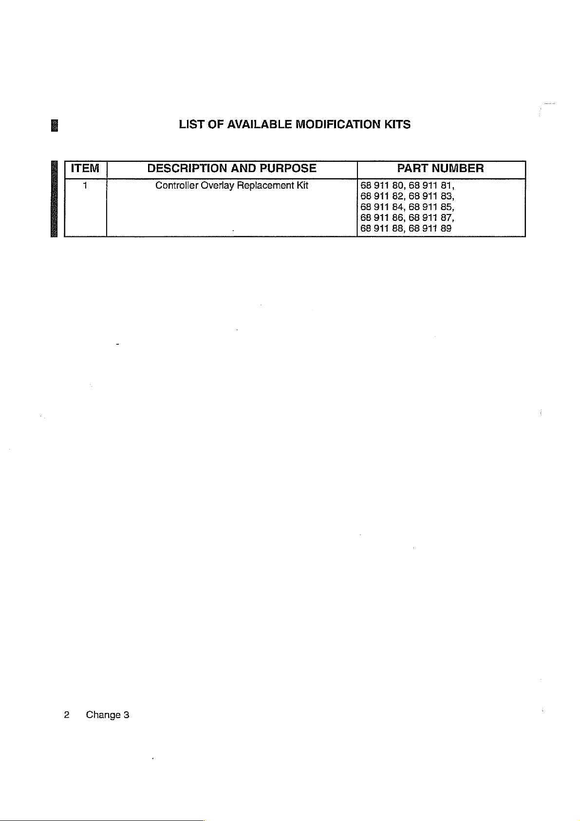
ITEM
LIST
OF
DESCRIPTION
Controller
Overlay
AVAILABLE
AND
PURPOSE
Replacement
MODIFICATION
Kit
68
68
68
68
68
KITS
911
911
911
911
911
PART
80,
68
82,
68
84,
68
86,
68
88,
68
NUMBER
911
81,
911
83,
911
85,
911
87,
917
89
2
Change
3
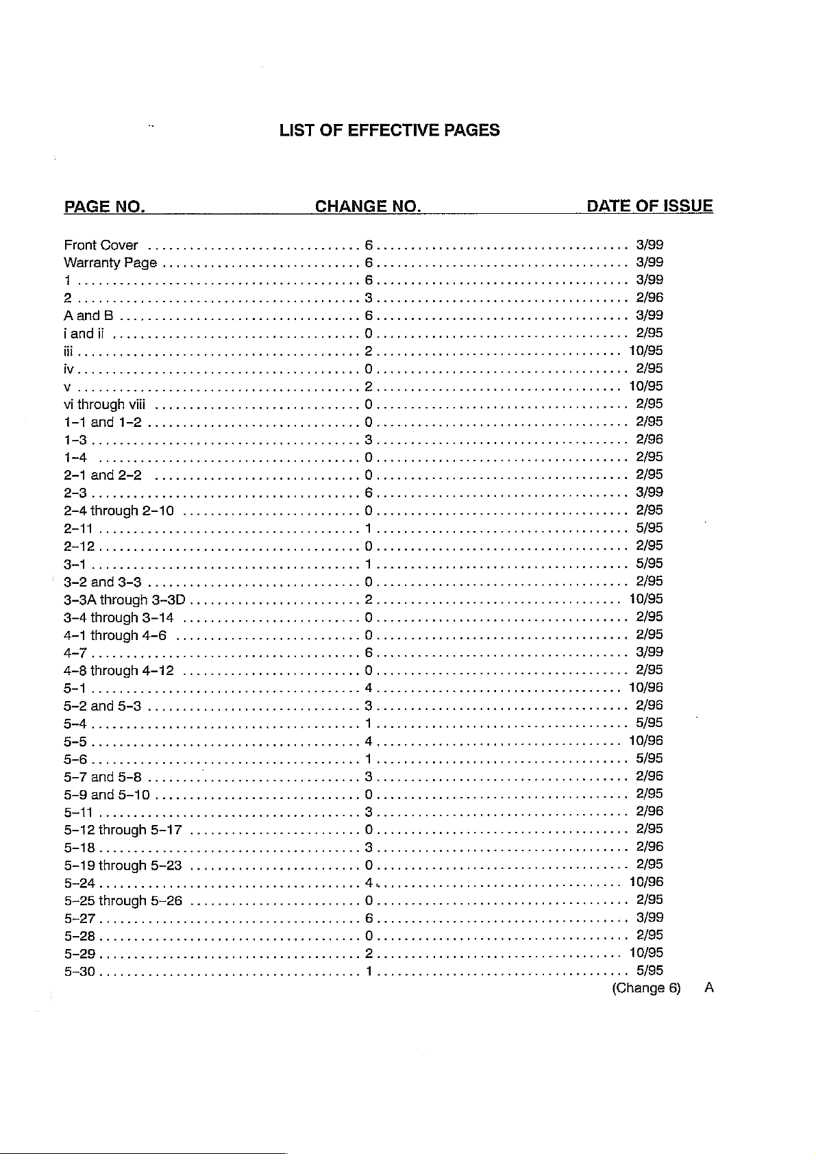
LIST
OF
EFFECTIVE
PAGES
PAGE
1-1
3-2 and
8-3A
3-4through3-14
4-1
BAT
4-8
NO.
and
1-2
3-3
through
through
aaa
through
..........
..........,..........,.........
4-6
4-12
ee
3-8D
................,........
..........................
..
CHANGE
nee
O...
0
0
2...
eee
NO.
DATE
K κ κε
εον
OF
2/95
2/95
10/95
ISSUE
5-12
5-19
5
5~25
5
through
A
through
through
5-17
5-23
5-26
(Change
6)
A
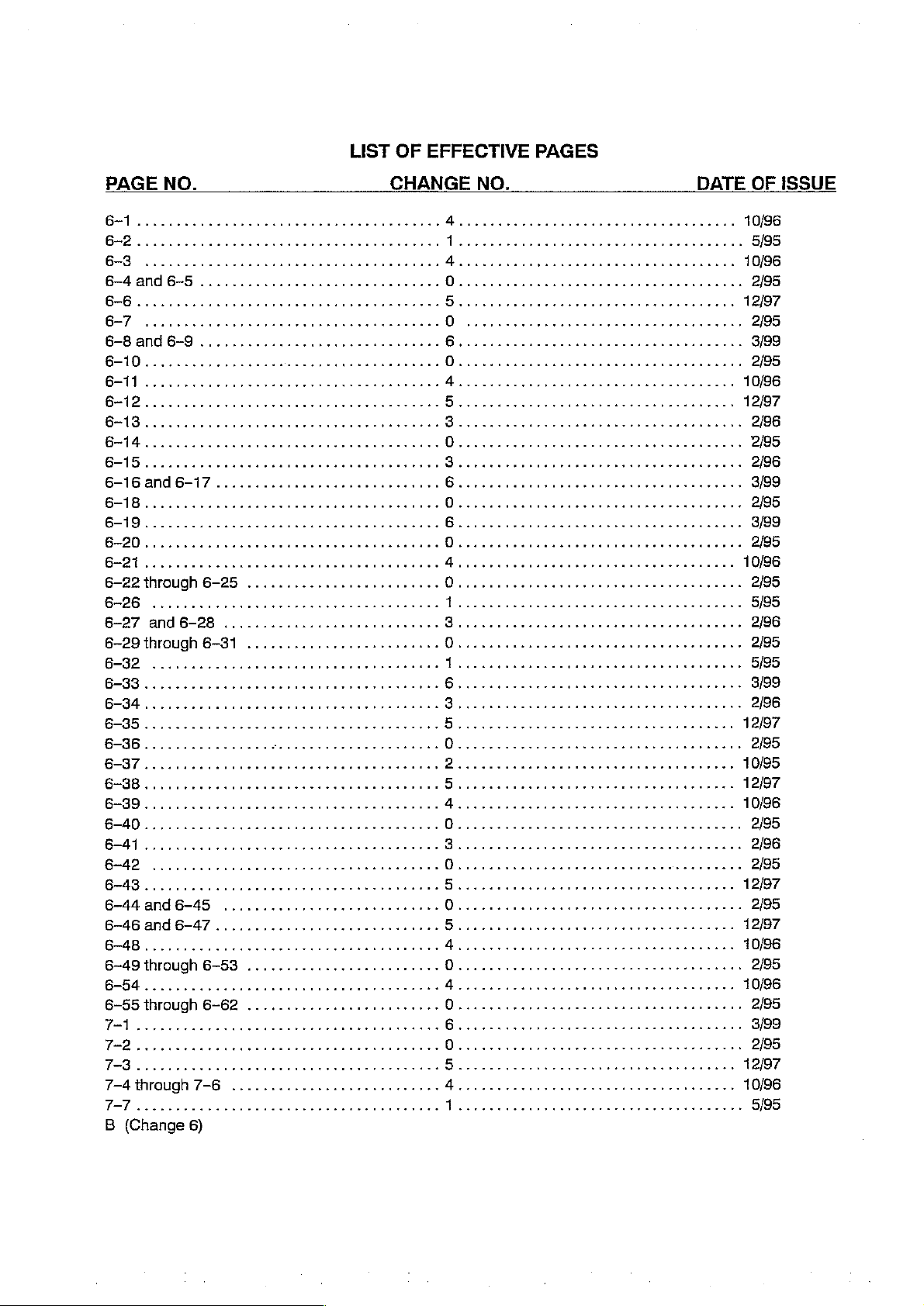
LIST
OF
EFFECTIVE
PAGES
PAGE
a
6-22
6-26
6-27
6-29
6-32
6
6-34 に に
6-35 1 eee
6—36............
EV
6-38........
¡AN
6
6-41
6-442
6~-483
6-44
6-46
4
6-49
Bcc
NO.
users
through
....,,...,....,...,,...,..........
and
through
44e.
cc
cesser
.......
and6-45
and
through
6-25
6-28
6-37
ear
6-47
6-53
CHANGE
...................,.....
............................ ド に
.........................
ron
rr
rr
rc
rr
rr
..........,..............,..
.............................
.........................
rr
rr
rr
rr
ro
ko
k
NO.
人
0
Dro
0
【
A
e
cesser
0
2......
iie
o
4
0
5
seeesremeteeesss
0
5
0
5
Arena
0
人
cee
tenet
rr
enn
esessnkee
ます
すす
cece
center
ence tent e eens
DATE
まま
まま
en
eee
10/96
아아
다아
12/97
10/95
12/97
10/96
12/97
12/97
10/96
10/96
OF
2/95
5/95
2/96
2/95
5/95
3/99
2/96
2/95
2/95
2/96
2/95
2/95
2/95
ISSUE
B
(Change
6)
TABLE
OF
CONTENTS
SECTION
1
GENERAL
1.1
INTRODUCTION
1.2
DESCRIPTION
1.3
ACCESSORIES
1.4
MODEL
2
INSTALLATION
2.1
UNPACKING
2.2
ASSEMBLY
2.3
ASSEMBLY
2.4
WARM
2.5
GENERAL
3
TECHNICAL
3.1
SPECIFICATIONS,
3.2
THEORY
321
3.2.2
3.2.3
3.2.4
3.2.5
3.2.6
3.2.7
3.2.8
3.3
DETAILED
3.3.1
3.3.2
INFORMATION
IDENTIFICATION
200...
-
INCUBATORS
—
INCUBATORS
WEIGH)
OF
GENERAL.................
OVERALL
TEMPERATURE
ALARMS
VERTICAL
CONTINUOUSLY
QUIET
SWIVEL
POWER
»e
e
в
e
MAIN/DISPLAY
INFANT SCALE,
OPERATION
INFORMATION
OPERATION
FUNCTIONAL
LATCHACCESS
SHELVES,
CIRCUIT
SUPPLY
GENERAL..................
HEATERCONTROL......................
LINE
MOTOR
..........
SERIES
cece
AND
CONTROL
HEIGHT
DESCRIPTION
REFERENCE
ADJUSTABLE
VARIABLE
CABINETS
..........
CONTROLLER
BOARD
000000
CHANGE
EQUIPPED
EQUIPPED
MODEL
FUNCTIONAL
ΡΕΡΟΗΙΡΤΙΟΝ
MATTRESS
DOOHNS
............L
(IEC
K
cere
WITH
WITH
I20
(ACCESSORY)
CHECKOUT
eee
STAND
AND
DRAWERS
CONTROLLERS
a
ии
ина
STANDARD
VERTICAL
e
cece
(OPTION,
TILT
MECHANISM
e
cee
K K K K K
иное R K K K K KR
CABINET
HEIGHT
PROCEDURE
44e
eee
K K P
REFER
(ACCESSORIES)
ene t eet
sisi
ONLY)
sun
esans
eee
ADJUSTABLE
TO
......
nent
K
K
S
K K
K K K
STAND
ーー
...............
トレ
トー
kk
sner k ker r rr
cesser
erer
K
FIGURE
1.1)
STAND
er
enee
sieurs
e ε κε ε κκ ε νοκ κ ον
K
n
トド
ーーー
renen
........
kk
PAGE
k
....
srnge
εως
sans
1-1
2-1
2-1
2-1
2-3
2-5
3-9
KEYPAD
SIGNAL
ALARMS
-…
High
一
SetPOointAIar
—
SystemFail.......................
—
PoewerFall
ー
Probe
—
AirFlow
ADCONVERTER..................
POWER
BATTERY
DISPLAYS
ντ νε
CONDITIONERS
..............
Temperature
Fail
..................
SUPPLY
CHARGER
ωω
εννοω
Alarm . «ων
.........................
MEASUREMENT
εν
eler
εν
εν
νεο ενω
eee
νννννω
2...
εν
εεοώνο
ενω
00
5.el
een
2222.
ενω
iie
이이다
νο νε
εκ ε ενω ν ένο ώ νε
ρω νε εν
οκ
0
0000111
ees
ela
아아아
eee
eee
ο
aerea
ων
ον
마
TABLE
OF
CONTENTS
(Cont.)
SECTION
3.3.3
4
PREVENTIVE
4.1
СЕМЕВАЕ........
4.2
CLEANING
4.2.2
4.3
GAS
STERILIZATION
5
SERVICE
5.1
GENERAL
5.2
CONTROLLER
5.2.1
®
ΑΙΟΡΙΟ
e
REMOTE
e
ACLINEVOLTAGECORRECTİON.............................
e
DC
PROBE BOARD
e
GENERAL
e
SERIAL
e
SKIN
MAINTENANCE
------ᾱ-υᾱ--ἷ,
„....
CLEANING
.......,.,..,,........,
GENERAL.....................
ΑΙΑΗΜ
ALARM
MOTOR
COMMUNICATION
PROBE
....,.,....,.....,...,.4.......44
AND
INCUBATOR
INTERFACE
CONTROL
CALIBRATION
FUNCTIONAL
(GROUP 2 CONTROLLERS
CHECK
ccc
cen
cence
4e
TESTS
eee
K
ee
ONLY)
L
ие
la
...................
K k n
еее
ниче
k
PAGE
3-12
3-13
3-13
3-13
e
5.3
CALIBRATION
5.3.1
5.3.2
5.3.3
5.4.1
5.4.2
5.4.3
PROCEDURE
PROCEDURES
TEST
EQUIPMENT
POWER
LOCATION
本
e
MAIN
LOCATION
*
GENERAL
TEST
ERROR
SUPPLY
OF
PROCEDURE
BOARD
OF
SET-UP............
EQUIPMENT
CODES
(REFER
.............
REQUIRED
(REFER
TEST
POINTS
............
TEST
POINTS
ενω
REQUIRED
..........
TO
FIGURES
AND
TO
FIGURE
AND
ρνων
5.1
ADJUSTMENTS)
5.2
FOR
ADJUSTMENTS)
ων
εως
нения
AND
eee
5.2
FOR
...............................
K
иене
rr
нение
어이
нее
eee e eens
тяеки
тия
5-7
5-7
5-7
TABLE
OF
CONTENTS
(Cont.)
SECTION
5.5.2
5.5.3
5.5.4
5.5.5
5.6
АСТЕАМАТМЕ
5.6.1
5.6.2
5.6.3
5.6.4
6
REPLACEMENT
6.1
GENERAL
6.2
RECOMMENDED
CONTROLLER
e
CONTROLLER
e
MAIN
e © POWER
e
РНРОВЕ
e
DUAL
OXYGEN
VHA
STAND
e
VHASTAND
®
UP/DOWNSWITCH
e
PHASE
REASSEMBLY
OUTER
35.89
39.30
36.00
36.00
COLUMN
ТЕЗТ
°C
BABY
°C
°C
AIR
°C
AIR
PARTS に に に 1 に
..
FRONT
PRINTED
SUPPLY
ВОАНО
AIR
TEMPERATURE
INPUT
HIGH
VALVE
eee
SHIFT
OF
ЕСШРМЕМТ
TEMPERATURE
TEMPERATURE
TEMPERATURE
TEMPERATURE
SPARE
PANEL
FRONT
CIRCUIT
„o
............
FILTER
ACTUATOR
CAPACITOR
INNER
(REFER
PARIS
COLUMN
TO
......
AND
CONTROLLER
PANEL
FIGURE
SIMULATION
SIMULATION
........
BOARD
PROBE
CARTRIDGE
.......................
нение
INTO
5.6)
нение
SIMULATION
SIMULATION
ce
.............
еее»
...........-
.............
GROUP 1 UNITS
GROUP 2 UNITS
ーー
eee
nee
PRINTED
cece
ect
ии
еек
няня
CIRCUIT
eee tee
еее
.....................
......,....,...,.....
неее
κεν
BOARDS
eee
eee e eens
r
sner
cnet
εεεο
ρε
κορν
ян
εν εκ εκ ε εν
te
тнтнни
чину
νεο
PAGE
...
knrer
neeees
ενος
ντε
εν
5-23
5-30
5—30
6-1
6-1
6-3
7
DIAGRAMS
71
GENERAL..................
...........
0000000000000
S K K K R K S K
(Change
2)
K
ο
rer
irere
7-1
7-1
证
LIST
OF
TABLES
(cont.)
TABLE
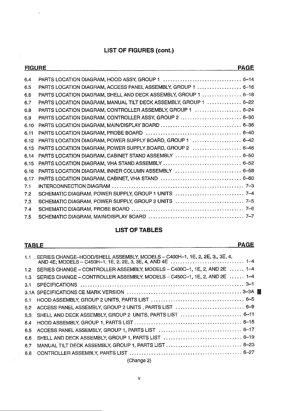
6.10
MAIN/DISPLAY
6.1
PROBE
6.12
POWER
6.13
POWER
6.14
CABINET
6.15
VHA
STAND
6.16
INNER
6.17
CABINET,
FLOWCHART
5.1
SYSTEM
5.1
SYSTEM
5.2
POWER
5.2
POWER
5.2
POWER
5.3
MAIN
5.3
MAIN
5.3.
MAIN
5.3
MAIN
5.3
MAIN
5.3
MAIN
BOARD,
SUPPLY
SUPPLY
STAND,
ASSEMBLY,
COLUMN
VHA
FAIL
FAIL
SUPPLY
SUPPLY
SUPPLY
BOARD
BOARD
BOARD
BOARD
BOARD
BOARD
BOARD,PARTSLISI
PARTS
BOARD
BOARD
ASSEMBLY,
STAND,
ALARM
ALARM
TROUBLESHOOTING
TROUBLESHOOTING
TROUBLESHOOTING
TROUBLESHOOTING
TROUBLESHOOTING
TROUBLESHOOTING
LIST
GROUP1,PARTSLIST...................
GROUP
ASSEMBLY,
PARTSLIST
PARTS
TROUBLESHOOTING
TROUBLESHOOTING
BOARD
BOARD
BOARD
TROUBLESHOOTING
TROUBLESHOOTING
TROUBLESHOOTING
PAHTS
«νε
2,
PARTS
LIST
LIST
....................
νωωνωενεννωνων
PARTS
LIST
OF
(Sheet 1 of
(Sheet 6 of
LIST
LIST
........
000000000
FLOWCHARTS
(Sheet10f2)............................
(Sheet 2 of
(Sheet 2 of
(Sheet 3 of
(Sheet 4 of
(Sheet 5 of
κε κ εκ
...................,...........,,.,.
2.0000
2)...................,.........
(Sheet 1 0f
(Sheet 2 of 3)
(Sheet 3 of 3)
6)
6)
6)
6)
6)
6)
eee
εν
ενος
κών
εν
νε
ν κ
ναών
00
ee
ee
0
3)
.........................
.........................
...................,.....
εκ εω
anes
νε
νο
ke
k
ne
PAGE
6-37
εν
6-41
6-43
6-47
6-51
6-54
6-59
PAGE
5-12
5-13
5-14
5-15
5-16
vi

TABLE
OF
DEFINITIONS
AND
SYMBOLS
TECHNICAL.
Control
by lines
Incubator
Zone. A plane
that
Temperature.
face.
Steady
not
Temperature
vary
more
Temperature
perature
during
Temperature
Temperature
above
the
mattress
dition.
mattress
The
four
surface.
Temperature
Temperature
DEFINITIONS
10
cm
divide
the
width
Air
Condition.
than
0.2
°C
Overshoot,
Steady
Rise
Time. The
Uniformity. The
surface
points
are the
Variation.
during
The
Steady
above
the
and
length
temperature
The
condition
over a period
The
amount
Temperature
time
required
amount
differs
from
centers
of
difference
Temperature
mattress
of
the
mattress
at a point
of
one
by
which
Condition,
for
by
which
the
average
four
quadrants
between
Condition.
with
an
10
cm
reached
hour.
Incubator
resulting
the
Incubator
the
average
Incubator
formed
the
Incubator
area
defined
surface.
(4
in.)
above
when
the
Temperature
from a change
Temperature
temperature
Temperature
by
Temperature
by
average
lines
that
the
center
and
centered
Incubator
exceeds
at
each
divide
of
four
over
average
in
temperature.
to
rise
11
of
four
at
Steady
the
width
and
the
quadrants
the
mattress
Temperature
Incubator
°С.
points
10
cm
Temperature
and
length
Average
Incubator
formed
sur-
does
Tem-
(4
in.)
Con-
of
the
vii
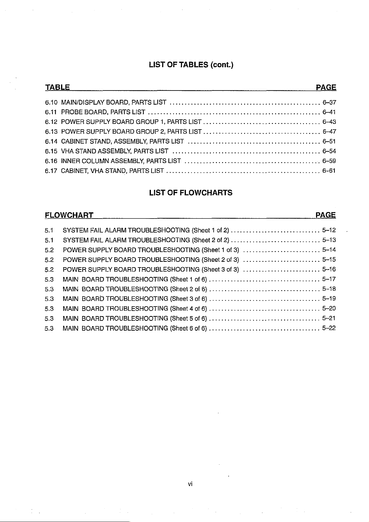
NOTE,
IMPORTANT,
CAUTION,
AND
WARNING
NOTE: A Note
or
IMPORTANT:
CAUTION:
WARNING:
inherent
sonal
injury
is
inserted
overlooked. A Note
Similar
A
Caution
can
lead
A
Warning
to
the
operation,
or
death
in
text
to a Note
is
inserted
to
damage
is
inserted
of
the
to
point
may
also
but
used
in
text
or
destruction
cleaning,
operator
out
procedures
be
where
to
in
text
and
or
used
to
clarify
greater
call
attention
of
the
to
call
attention
maintenance
patient.
or
conditions
apparently
emphasis
to a procedure
equipment
to
of
the
which
may
contradictory
is
required.
which,
or
improper
dangerous
equipment
otherwise
or
confusing
if
not
operation.
or
hazardous
which
may
be
misinterpreted
situations.
followed
result
exactly,
conditions
in
per-
SYMBOLS
Attention;
Type B eguipment
isolated
consult
(floating)
accompanying
with
applied
an
F-type
part.
documents.
M
©
Set
Temperature
Set
Temperature
Up
Key
Down
Key
Caution:
Refer
PaP
AC
power.
Protective
©,
Air
»
Mode
Baby
=
Air
Mode
Electric
ice
service
Earth
Control
Mode
Control
Control
shock
t
to
qualified
(ground).
Indicator
Indicator
Selection
hazard.
ified
personne
Key
|.
©
>87º
|
©
©
、
Keypad
Keypad
Lock
Lock
Temperature
Indicator
Temperature
Selection
Silence/Reset
Key
Indicator
Key
Override
Override
Key
Mode
Mode
© @
Baby
Mode
Control
Selection
Key
viii
POWER
De
On/Off
Switch

GENERAL
C400/C450
INFORMATION
1.1
INTRODUCTION
This
manual
Models
This
manual
the
equipment
1.2
DESCRIPTION
The
forced
distribution,
oxygen
Entry
Ports.
mattress
the
hood
operating
Baby
or
for
air
heater
feature.The
provides
C400
is
air
humidification,
concentrations.
When
toward
environment.
temperature
Air
Temperature
temperature
output,
Models
instructions
QT™
and
C450
QT™.
intended
are
circulation
for
provided
use
only
in a separate
system
effective
Accessibility
the
Access
the top
The
range
control.
and a comprehensive
C400
Panel
of
the
Access
Incubator
of
20
Control
is
Instrumentation
QT™
GENERAL
for
installation,
by
trained,
operator's
of
the
isolation
to
the
is
open, a curtain
Panel
is
designed
to
30
°C. A guard
selected
visual
and
C450
SECTION
INFORMATION
maintenance
qualified
manual.
Incubator
of
the
infant
is
provided
opening;
by a front
includes
QT™
this
for
use
rail
panel
and
audible
Incubators
digital
1
and
service
permits
infant
of
stable
from
by
warm
air
air
curtain
in a nursery
is
optional
control.
display
alarm
also
repair
of
the
personnel.
temperature
airborne
an
Access
flows
from
minimizes
environment
on
all
units.
The Model
for
temperature,
system
include
which
the
Isolette®
Instructions
Infant
for
control,
contaminants,
Panel,
Access
beneath
the
the
front
temperature
having a typical
On
the
Model
C400
QT™
is
relative
includes
following
features:
Incubators,
the
operator
uniform
and
control
Doors,
and
edge
drop
ambient
C450
equipped
indication
an
alarm
of
heat
of
Iris
of
the
within
QT™,
only
of
test
*
Oval
Access
*
The
Mattress
ㆍ
Optional
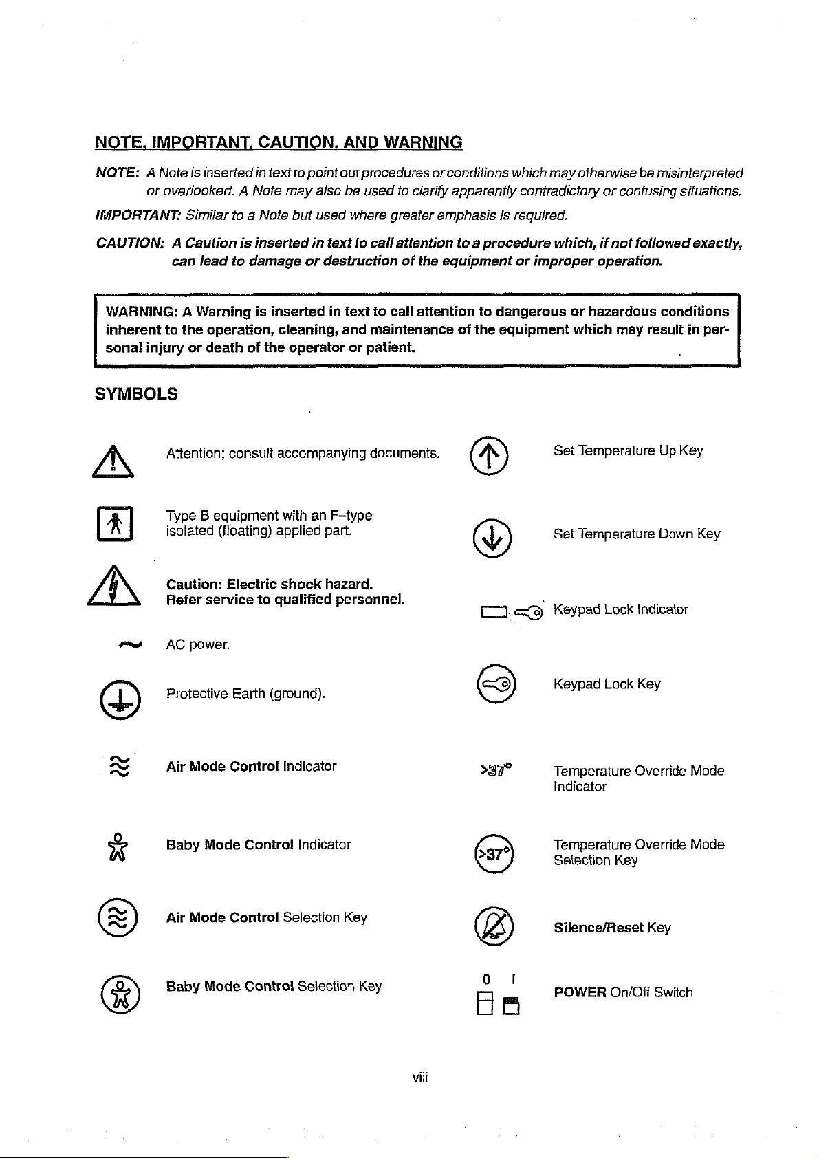
1.3
ACCESSORIES
Accessories
manual
ㆍ
*
・
*
*
®
>
s
9
9
for
Cabinet
Guard
Rail
System
VHA
(Vertical
Rail
System
SOLAIR™
MICRO-LITE™
DEW-ETTE®
Remote
WARM
+ | Monitor
s
ATHENA®
»
АТНЕМА®
®
Utility
Pole
s
INV.
Tree
Doors
Tilt
VHA
Stand
available
part
numbers.
Stand
Rail
Standard
Height
for
Transparent
2
Alarm
WEİGHG©
Shelf
Package
Shelf
РАМ
Assembly
Assembly
with a Quiet
Mechanism
for
use
Cabinet
Adjustable
VHA
Stand
Hood
Phototherapy
Incubator
Module
Infant
Scale,
Assembly
Mounting
Latch
continuously
with
the
Incubators
Stand
Stand)
Warmer
System
Humidifier
Model
Kit
(Not
Shown)
(Not
120
variable
are
Shown)
(Refer
to
from
0°
to
illustrated
s
Oxygen
©
Air
Flow
s
Suction
e
Blender
Figure
2.5)
9º
from
in
Figure
Flowmeter
Kit
Kit
Kit
either
1.1.
(Not
(Not
Shown)
(Not
Shown)
end
Refer
Kit
Shown)
to
Section 6 of
(Not
Shown)
this
C400/C450
GENERAL
INFORMATION
Double
Stub
Mount
Monitor
Shelf
DEW-ETTE®
Micro--Lite”
Humidifer
Phototherapy
Remote
Exam
W
Tree
Light
Alarmf:
—..
Utility
Pole
Rail
Syste"
Guard
VHA
Stand
FIGURE
1.1
and
Cabinets
ACCESSORIES

1.4
MODEL
The
Isolette®
identification
IDENTIFICATION
Infant
and
Incubators,
series
number.
SERIES
Models
The
locations
C400
CHANGE
QT™
of
the
and
C450
data tags
QT™,
are
have
as
follows:
GENERAL
two
data
INFORMATION
tags
which
0400/0450
list
model
CONTROLLER:
HOOD/SHELL
The
following
MODEL
UNIT
DESIGNATION
EXPORT
SERIES
DESIGN
The
Isolette®
three
Controller
GROUP
The
be
identified
The
The
Data
Hood
Access
NUMBER
Tag
has two
Located
ASSEMBLY:
example
explains
IDENTIFICATION
CHANGE
CHANGE
Infant
(MODE
LEVEL)
Incubators,
Assemblies.
1
on
the
Hood/Shell
by
the
following
Tubing
Panel
has
an
on
the
top
panel
Located
the
on
content
C400H ~ 1
İİ
Models
of
Group 1 carries
characteristics:
Access
Inner
Grommets,
Wall
(refer
of
the
C400
the
Controller.
right
side
of
the
QT™
one
to
Figure
panel
data
tag:
and
the
Model
located
6.5).
of
C450
No.
on
the
Shell.
QT™,
C400H-1
either
have
side
two
(1E)
(Refer
00
different
or
C450H-1
to
Figure
Hood/Shell
(1E)
and
6.4).
and
can
The
The
be
The
The
7
The
GROUP
The
C450H-2,
The
The
The
Π
The
be
The
The
Я
The
Main
Deck
is
held
in
Data
Tag
on
the
Controller
identified
Controller
Controller
Auxiliary
Data
Hood
Access
Main
Data
identified
Controller
Controller has a keying
Auxiliary
by
is
does
Air
NUMBER
Tag
on
3,
or 4 (2E,
has
four
Panel
Deck
Tag
on
by
is
Air
the
following
equipped
not
Probe
2
the
Hood/Shell
3E
Tubing
does
consists
the
Controller
the
following
equipped
Probe
place
by a Retainer
of
Group 1 carries
characteristics:
with
an
ac
have a keying
is a single
or
Access
not
of
the
thermistor
of
Group 2 carries
4E)
and
Grommets,
have
an
Deck
of
Group 2 carries
characteristics:
with a round
pin
located
is a dual
thermistor
motor.
pin
can
be
Inner
Plate
de
between
Knob
the
located
between
probe.
identified
two
located
Wall.
and
Main
the
motor.
the
probe.
(Change
(Refer
Model
the
Model
by
the
Deck
Model
Impeller
3)
to
Figure
No.
C400C-1
the
Impeller
No.
following
on
either
(refer
to
No.
C400C-2
and
4.5).
(1E)
or
C450C-1
and
Heater
Coil.
C400H-2, 3 or 4 (2E,
characteristics:
side
(Refer
to
Figure
Figures
Heater
4.6
(2E)
Coil.
and
or
C450C-2
4.7).
(1E)
3E
6.1).
(2E)
and
or
and
can
4E)
can
or
1-3
C400/C450
GENERAL
INFORMATION
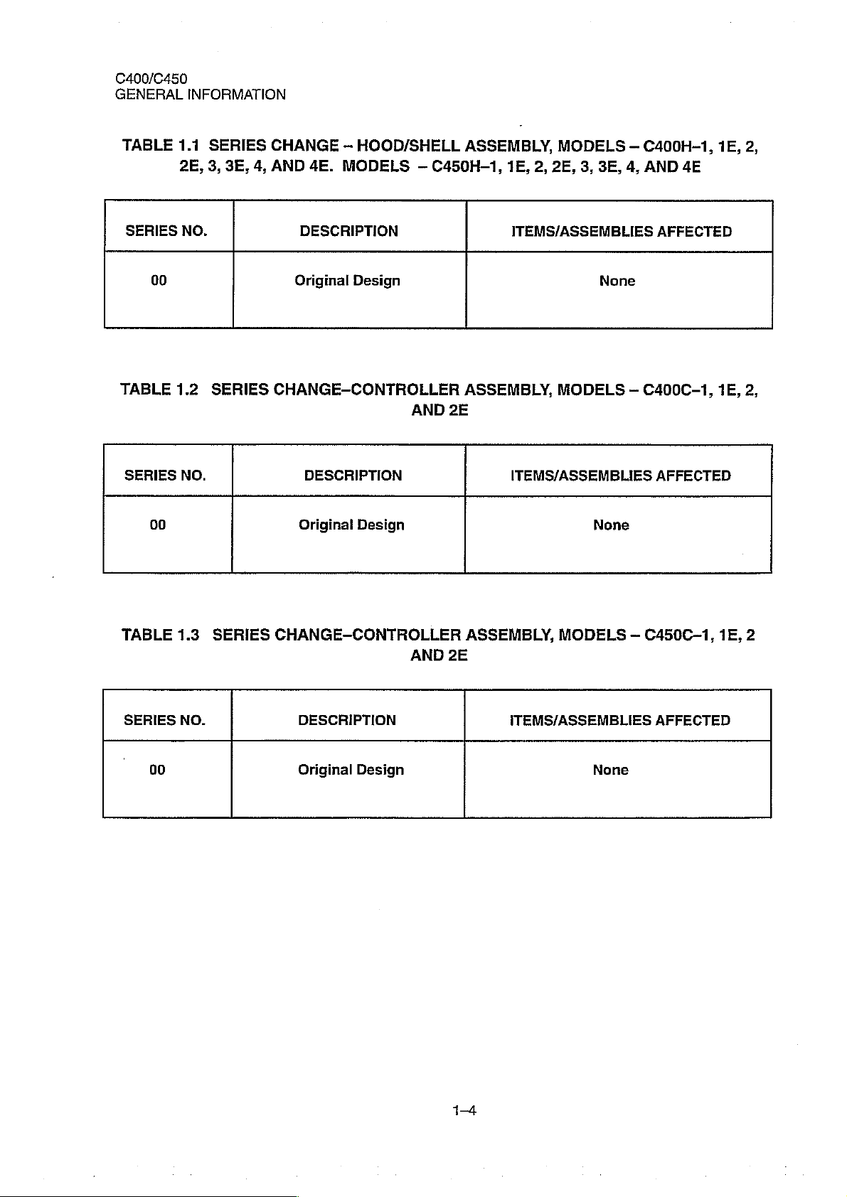
TABLE
SERIES
TABLE
SERIES
00
00
1.1
2E,
NO.
1.2
NO.
SERIES
3,
3E,
SERIES
CHANGE
4,
AND
DESCRIPTION
Original
CHANGE-CONTROLLER
Original
-
HOOD/SHELL
4E.
MODELS
Design
DESCRIPTION
Design
—
C450H-1,
AND
2E
ASSEMBLY,
1E,
ITEMS/ASSEMBLIES
ASSEMBLY,
ITEMS/ASSEMBLIES
2,
2E,
MODELS
3,
3E,
None
MODELS
None
—
C400H-1,
4,
AND
AFFECTED
—
C400C-1,
AFFECTED
4E
1E,
1E,
2,
2,
TABLE
SERIES
00
1.3
NO.
SERIES
CHANGE-CONTROLLER
DESCRIPTION
Original
Design
AND
ASSEMBLY,
2E
MODELS
ITEMS/ASSEMBLIES
None
—
C450C-1,
AFFECTED
1E,
2
14
C400/C450
INSTALLATION
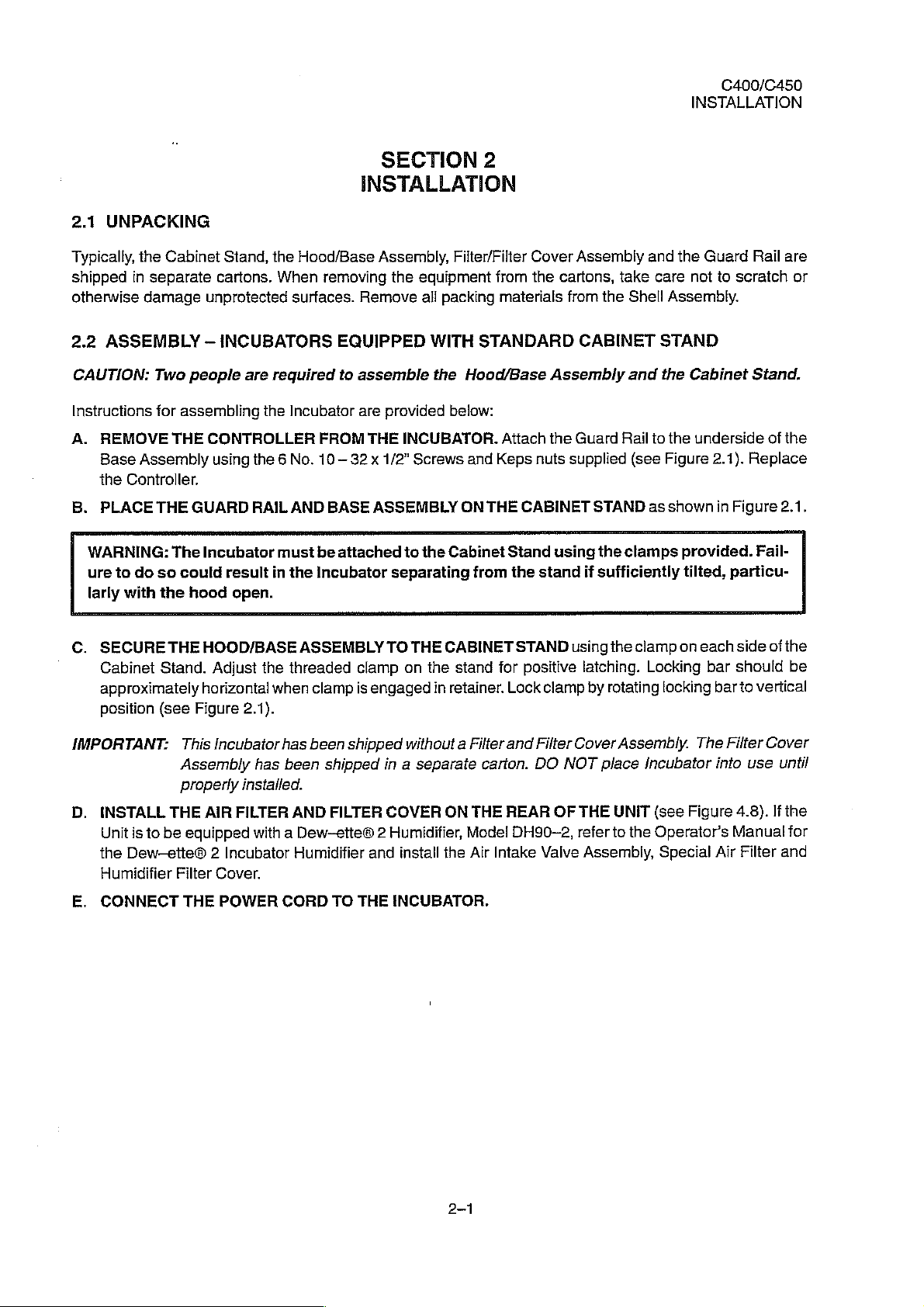
2.1
UNPACKING
Typically,
shipped
otherwise
2.2
CAUTION:
Instructions
A.
B.
WARNING:
ure
larly
the
in
separate
damage
ASSEMBLY
REMOVE
Base
Assembly
the
Controller.
PLACE
to
do
with
Two
for
THE
Cabinet
unprotected
—
people
assembling
THE
CONTROLLER
GUARD
The
Incubator
so
could
the
hood
Stand,
cartons.
the
When
INCUBATORS
are
required
the
using
the 6 No.
RAIL
result
in
open.
Hood/Base
removing
surfaces.
Incubator
FROM
10—
AND
BASE
must
be
the
Incubator
SECTION
INSTALLATION
Assembly,
the
equipment
Remove
EQUIPPED
to
assemble
are
THE
32 x 1/2”
ASSEMBLY
attached
all
packing
WITH
the
provided
INCUBATOR.
Screws
to
the
separating
2
Filter/Filter
from
materials
STANDARD
Hood/Base
below:
Attach
and
Keps
ON
THE
CABINET
Cabinet
from
Stand
the
Cover
the
cartons,
Assembly
the
nuts
using
stand
Assembly
take
from
the
CABINET
Guard
Rail
supplied
STAND
the
clamps
if
sufficiently
and
care
Shell
and
to
(see
as
the
Guard
not
Assembly.
STAND
the
Cabinet
the
underside
Figure
shown
provided.
tilted,
to
scratch
Stand.
2.1).
Replace
in
Figure
particu-
Rail
of
Fail-
are
or
the
2.1.
C.
SECURE
Cabinet
approximately
position
IMPORTANT:
D.
INSTALL
Unit
is
the
Dew—ette@® 2 Incubator
Humidifier
E.
CONNECT
THE
Stand.
(see
THE
to
be
HOOD/BASE
Adjust
horizontal
Figure
This
Incubator
Assembly
properly
AIR
equipped
Filter
Cover.
THE
POWER
the
when
ASSEMBLY
threaded
clamp
TO
clamp
is
engaged
THE
on
the
in
2.1).
has
been
has
been
installed.
FILTER
AND
shipped
shipped
FILTER
without a Filter
in a separate
COVER
with a Dew-ette® 2 Humidifier,
Humidifier
CORD
TO
and
THE
install
INCUBATOR.
CABINET
stand
retainer.
carton.
ON
THE
Model
the
Air
Intake
STAND
for
positive
Lock
and
DO
REAR
DH90~2,
using
clamp
Filter
Cover
NOT
OF
refer
Valve
the
clamp
latching.
by
rotating
Assembly.
place
THE
UNIT
to
the
Assembly,
on
each
Locking
bar
locking
The
Incubator
(see
Figure
Operator’s
Special
side
should
bar
to
Filter
into
4.8).
Manual
Air
Filter
of
the
vertical
Cover
use
until
lfthe
for
and
be
C400/C450
INSTALLATION
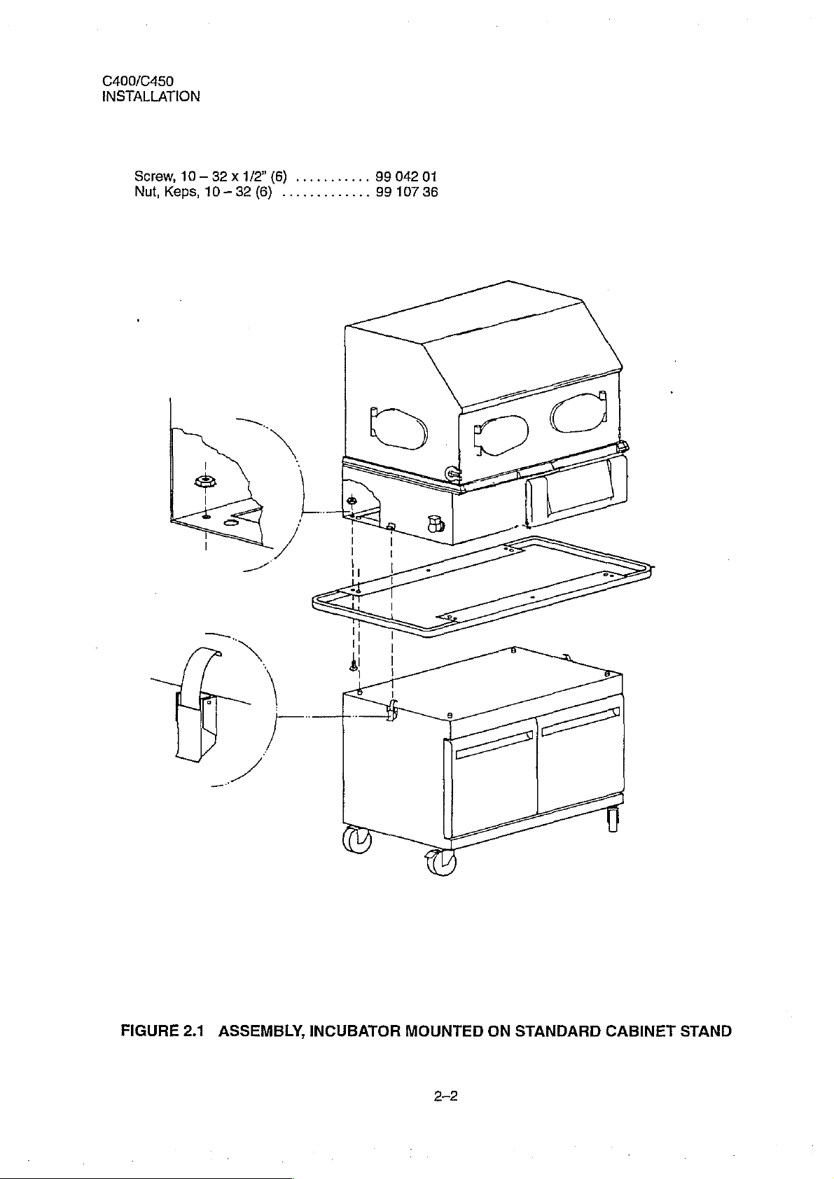
Screw,
Nut,
Keps,
10—
32 x 1/2"
10-32
(6)
...........
(6)
.............
99
99
042
107
01
36
FIGURE
2.1
ASSEMBLY,
INCUBATOR
MOUNTED
2-2
ON
STANDARD
CABINET
STAND
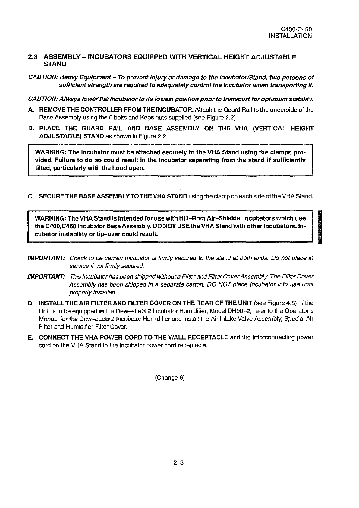
2.3
ASSEMBLY
STAND
-
INCUBATORS
EQUIPPED
WITH
VERTICAL
HEIGHT
C400/C450
INSTALLATION
ADJUSTABLE
CAUTION:
CAUTION:
A.
REMOVE
Base
B.
PLACE
ADJUSTABLE)
WARNING:
vided.
tilted,
C.
SECURE
WARNING:
the
C400/C450
cubator
Heavy
sufficient
Always
Assembly
Failure
particularly
instability
Equipment - To
strength
lower
THE
CONTROLLER
using
THE
GUARD
STAND
The
Incubator
to
do
with
THE
BASE
The
VHA
incubator
the
the 6 bolts
as
so
could
the
ASSEMBLY
Stand
Base
or
tip-over
prevent
are
required
Incubator
FROM
and
RAIL
shown
must
result
hood
is
intended
Assembly.
could
AND
in
be
open.
TO
Injury
to
to
its
THE
Keps
BASE
Figure
attached securely
in
the
THE
for
result.
or
damage
adequately
lowest
nuts
VHA
use
DO
position
INCUBATOR.
supplied
ASSEMBLY
2.2.
Incubator
STAND
with
NOT
USE
Hill-Rom
to
the
control
(see
to
separating
using
the
the
prior
to
Attach
the
Figure
ON
the
VHA
the
clamp
Air-Shields’
VHA
Stand
Incubator/Stand,
Incubator
transport
Guard
2.2).
THE
Stand
from
on
with
when
for
Rail
to
VHA
(VERTICAL
using
the
stand
each
side
Incubators
other
optimum
the
the
two
persons
transporting
stability.
underside
HEIGHT
clamps
if
sufficiently
of
the
Incubators.
pro-
VHA
which
of
it.
of
the
Stand.
use
in-
IMPORTANT:
IMPORTANT:
D.
INSTALL
Unit
is
Manual
Filter
and
E.
CONNECT
cord
on
Check
service
This
Assembly
properly
THE
to
be
equipped
for
the
Humidifier
THE
the
VHA
to
be
certain
if
not
firmly
incubator
has
installed.
AIR
FILTER
with a Dew-ette® 2 Incubator
Dew~ette® 2 Incubator
Filter
VHA
POWER
Stand
to
secured.
has
been
been
AND
Cover.
the
Incubator
Incubator
shipped
shipped
FILTER
CORD
is
firmly
withaut a Filter
in a separate
COVER
Humidifier
TO
THE
WALL
power
cord
(Change
secured
carton,
ON
THE
REAR
Humidifier,
and
install
RECEPTACLE
receptacle.
6)
to
and
the
the
stand
Filter
DO
NOT
OF
Model
Air
at
Cover
place
THE
DH90-2,
Intake
and
bath ends.
Assembly.
Incubator
UNIT
(see
refer
Valve
Assembly,
the
interconnecting
Da
not
The
Filter
into
Figure
to
the
place
in
Cover
use
until
4.8).
If
the
Operator’s
Special
Air
power
C400/C450
INSTALLATION
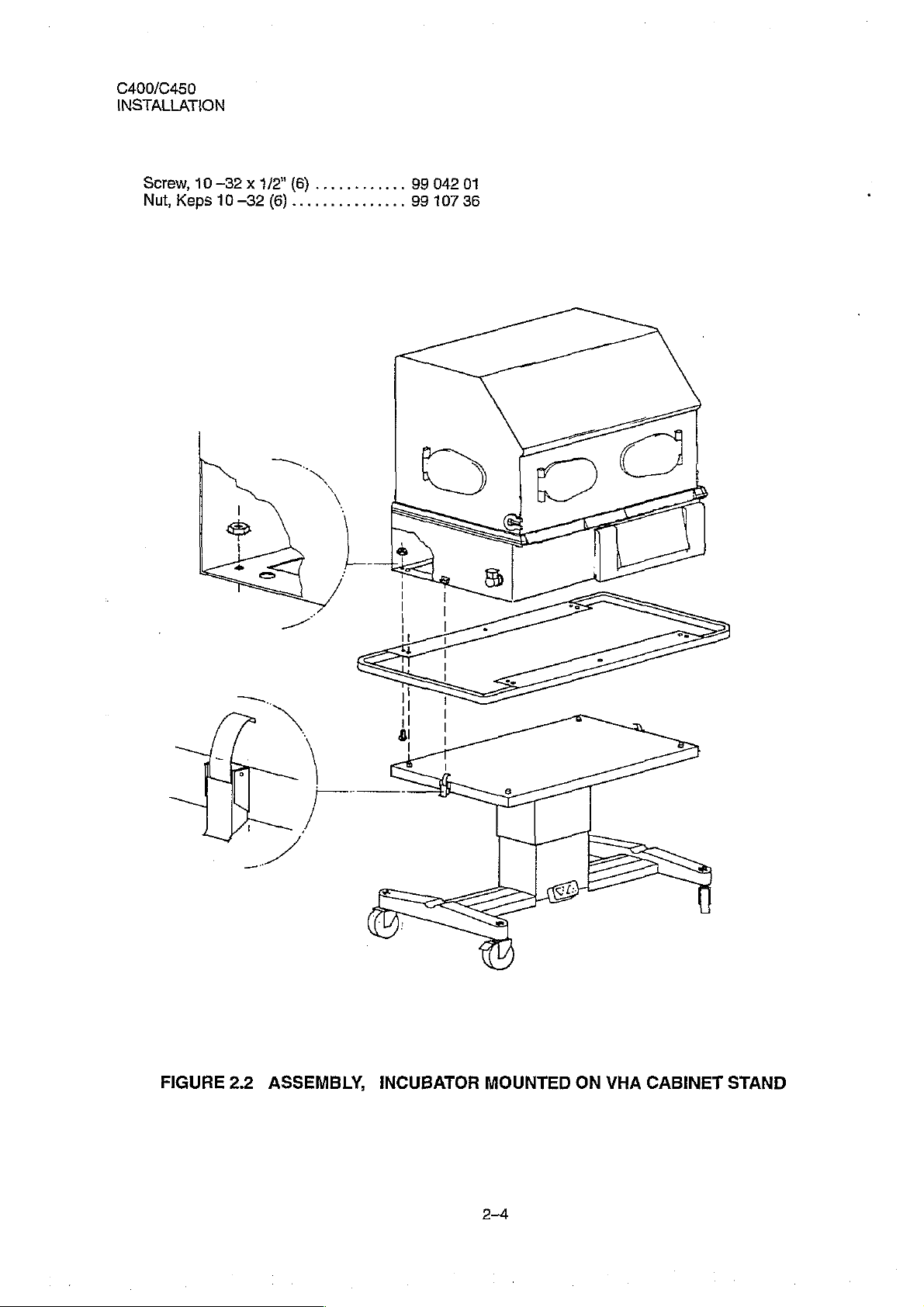
Screw,
Nut,
Keps
10
-32 x 1/2"
10-32
(6)
............
(6)
...............
99
99
042
107
01
36
FIGURE
2.2
ASSEMBLY,
INCUBATOR
MOUNTED
2-4
ON
VHA
CABINET
STAND
2.4
For
WARM
more
information,
WEIGH®
INFANT
refer
to
the
SCALE,
120/W30
MODEL
Operator's
120
(ACCESSORY)
Manual.
C400/C450
INSTALLATION
IMPORTANT:
A.
OPEN
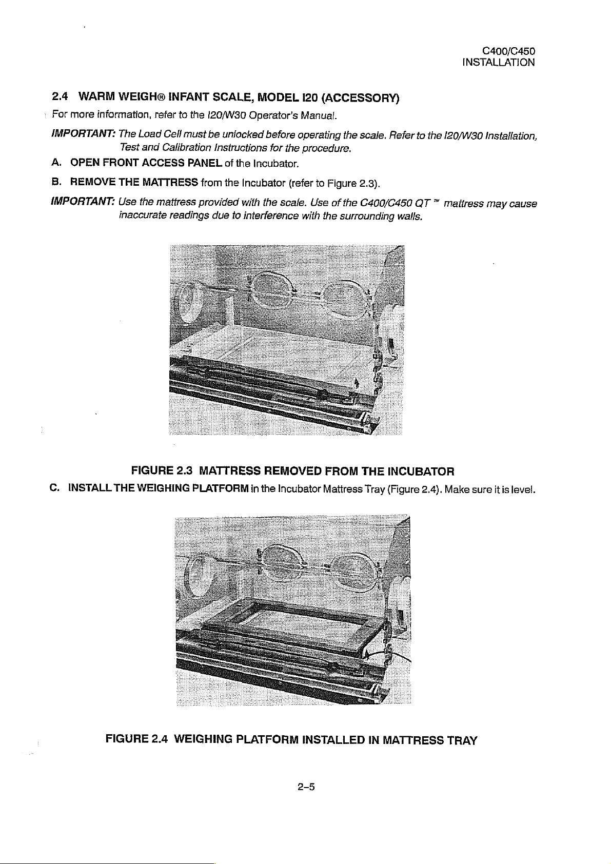
B.
REMOVE
IMPORTANT:
The
Test
FRONT
THE
Use
inaccurate
Load
Cell
Calibration
and
ACCESS
MATTRESS
the
mattress
readings
must
PANEL
from
provided
be
unlocked
Instructions
of
the
Incubator.
the
Incubator
with
interference
to
due
before
the
for
the
scale.
operating
procedure.
(refer
to
Use
the
with
the
scale.
Figure
2.3).
of
the
C400/C450
surrounding
Refer
walls.
to
QT
the
120/W30
™
mattress
Installation,
may
cause
C.
INSTALL
FIGURE
THE
WEIGHING
FIGURE
2.4
2.3
MATTRESS
PLATFORM
WEIGHING
REMOVED
in
the
Incubator
PLATFORM
FROM
Mattress
INSTALLED
THE
Tray
IN
MATTRESS
INCUBATOR
(Figure
2.4).
Make
TRAY
sure
itis
level.
C400/C450
INSTALLATION
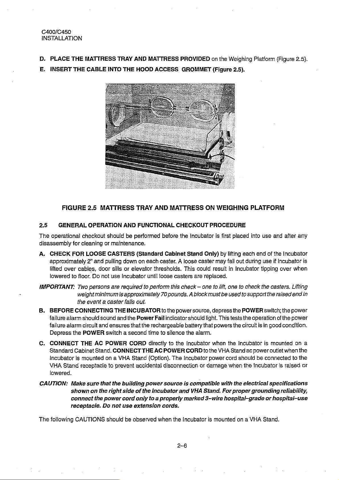
D.
PLACE
E.
INSERT
THE
THE
MATTRESS
CABLE
TRAY
INTO
THE
AND
HOOD
MATTRESS
ACCESS
PROVIDED
GROMMET
on
the
(Figure
Weighing
2.5).
Platform
(Figure
2.5).
FIGURE
2.5
The
disassembiy
A.
IMPORTANT:
6.
C.
GENERAL
operational
CHECK
approximately
lifted
over
lowered
BEFORE
failure
alarm
failure
alarm
Depress
CONNECT
Standard
Incubator
VHA
Stand
lowered.
2.5
OPERATION
checkout
for
cleaning
FOR
LOOSE
2”
and
cables,
to
floor.
Do
Two
persons
weight
the
CONNECTING
the
Cabinet
is
minimum
event a caster
should
circuit
POWER
THE
AC
mounted
receptacle
MATTRESS
should
or
maintenance.
CASTERS
pulling
door
sills
not
use
Incubator
are
required
is
THE
sound
and
and
ensures
switch a second
POWER
Stand.
CONNECT
on a VHA
to
prevent
TRAY
AND
be
performed
AND
FUNCTIONAL
(Standard
down
on
each
or
elevator
thresholds.
until
to
perform
approximately
falls
out.
INCUBATOR
the
Power
that
Fail
the
rechargeable
time
CORD
THE
Stand
directly
AC
(Option).
accidental
MATTRESS
CHECKOUT
before
caster. A loose
loose
70
to
to
the
Incubator
Cabinet Stand
This
casters
this
are
check — one
pounds. A block
the
power
source,
indicator
silence
to
POWER
battery
the
The
should
the
Incubator
CORD
Incubator
disconnection
ON
PROCEDURE
Only)
caster
could
replaced.
must
light.
that
alarm.
to
the
power
or
damage
WEIGHING
is
first
placed
by
lifting
may
fall
result
in
to.lift,
one
be
used
depress
powers
when
This
VHA
cord
the
tests the
the
the
Stand
when
PLATFORM
into
each
end
out
during
Incubator
to
check
to
support
POWER
operation
circuit
is
Incubator
ac
power
should
be
the
incubator
use and
of
the
use
if
Incubator
tipping
the
over
casters.
the
raised
switch;
of
in
good
is
mounted
outlet
connected
is
after
any
Incubator
is
when
Lifting
end
in
the
power
the
power
condition.
on
a
when
the
to
the
raised
or
CAUTION:
The
following
Make
sure
shown
connect
receptacle.
on
the
CAUTIONS
that
the
power
Do
should
the
right
not
building
side
of
the
cord
only
use
extension
be
observed
power
source
Incubator
to a properly
cords.
when
is
and
marked
the
Incubator
2-6
compatible
VHA
Stand.
3-wire
is
mounted
with
the
electrical
For
proper
grounding
hospital-grade
on a VHA
specifications
reliability,
or
hospital-use
Stand.
 Loading...