

Air-Shields C500QT, C550QT User manual
PLEASE
READ
Please
Since
component
incorporated
separate
package.
to
THIS
Hili-Rom
the
changed
MANUAL
check
improvements
into
sheets
Changed
MODIFICATIONS
TO
MAINTAIN
CANNOT
OPERATION
OR
ASSUME
OF
MODIFICATION.
NOTE
Some
parts
used
this
manual.
function
for a listing
of
This
the
of
the A page
Air-Shields
the
printed
at
the
rear
material
material,
CONTAINS
SHOULD
YOUR
WARRANTY
RESPONSIBILITY
THIS
EQUIPMENT
ON
in
your
equipment
sometimes
equipment.
recommended
for
change
information.
conducts a continuous
are
sometimes
manuals.
of
the
on
each
as
shown
PROPRIETARY
BE
PERFORMED
manual
page
on
WHICH
When
of
the
right.
AND
FOR ANY
incorporated
this
or
under separate
text
is
indicated
INFORMATION.
ONLY
TO
AVOID
CONDITIONS
MAY
RESULT
REPLACEMENT
may
be
different
occurs
Order
the
spare
NOTE:
due
to
part
listed
parts.
ALSO
difficulty
in
the
SEE
product
into
occurs,
BY
QUALIFIED
CREATING
than
those
in
parts
Parts
List.
PAGE
improvement
equipment
changed
by a vertical
cover
material
in
REPAIRS
SERVICE
SAFETY
AFFECTING
FROM
procurement,
UNAUTHORIZED
which
appear
Refer
to
Section 6 of
2.
program,
before
the
form
bar
in
AND
circuit
they
is
provided
of a change
the
margin
AUTHORIZED
PERSONNEL
HAZARDS.
THE
PROPER
PARTS
in
the
Parts
but
does
not
this
and
can
be
on
next
WE
REPAIR
List
alter
the
Manual
of
Change
7
1
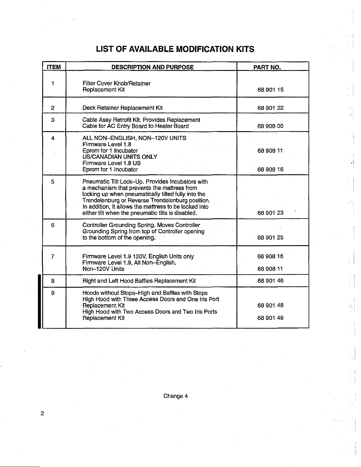
ITEM
LIST
Filter
Cover
Replacement
Deck
Retainer
Cable
Cable
ALL
NON-ENGLISH,
Firmware
Eprom
US/CANADIAN
Firmware
Eprom
Pneumatic
a
mechanism
locking
Trendelenburg
In
addition,
either
Controller
Grounding
to
the
OF
DESCRIPTION
Knob/Retainer
Kit
Assy
Retrofit
for
AC
Entry
Level
for 1 Incubator
Level
for 1 Incubator
Tilt
that
up
when
it
allows
tilt
when
Grounding
Spring
bottom
of
AVAILABLE
AND
Replacement
Kit.
Provides
Board
to
NON-120V
1.8
UNITS
1.8
Lock—Up.
or
the
the
ONLY
US
Provides
prevents
pneumatically
Reverse
pneumatic
from
Trendelenburg
the
mattress
Spring.
top
of
opening.
PURPOSE
Kit
Replacement
Heater
UNITS
Incubators
the
mattress
tilted
to
tilts
is
Moves
Controller
MODIFICATION
Board
with
from
fully
into
the
position.
be
locked
disabled.
Controller
‘
into
opening
KITS
PART
68
68 901
68
68
68
68
68
NO.
901
908
908
908
901
901
15
22
00
11
16
23
25
Firmware
Firmware
Non-120V
Right
and
Hoods
High
Replacement
High
Replacement
without
Hood
Hood
Level
Level
Units
Left
with
Kit
with
Kit
1.9
120V,
1.9,
All
Non-English,
Hood
Baffles
Stops—High
Three
Access
Two
Access
English
and
Units
Replacement
Baffles
Doors
Doors
and
Change
only
with
and
Two
Kit
One
4
Stops
Iris
Iris
Ports
Port
68
908
16
、
68
908
11
68
68
68
90146
901
901
.
48
48

LIST
PAGE
NO.
A
through
ithroughili...................................
D
OF
EFFECTIVE
viii
through
1-1
and 1-2
xii
CHANGE
PAGES
PAGE
2-15
through
2-23
and
PA
É
ентот
3-2 and
3-4
and3-5
3-6
2-22
....
2-24
....,....,,....................
10000
lielesesa
3-3
......................,...,,.....
ине
νο
νε ν κε
κκ ρ εν
εν ων
k
Change
7
A
LIST
OF
EFFECTIVE
PAGES
(coni.)
PAGE
3-28
3-32
NO.
through
through
3-31
3-36
.....................,.....
......................,.,...
CHANGE
0
2
PAGE
4-11
and
4-12
iii
5-1
through
5-37
and
5-39
and
5-58
through
5-63
through
5-66
6-1
rr
B
5-36
...........,,...,,...,.......
5-38
5-40
5-62
...................,...,...
5-65
...........................
......................,.,...............
Do
0
0
1
0
2
Change.7
lala
11/99
5/92
5/92
2/93
5/82
8/93
PAGE
NO.
LIST
OF
EFFECTIVE
CHANGE
PAGES
(cont.)
PAGE
BD
6-9
through
6-12
and
6-25
6-11
6-18
ーー
4
し に し
ーー 이 7
し
に
ここ
ーーー
net
O
TL
ετεκ
τε ν ετεκ
εκτ
ετκ
εν
....
k
εκτ
11/99
11/99
τον
11/99
.
6/94
3/95
8/96
5/92
6/94
8/96
5/92
8/93
5/92
8/93
5/92
2/93
8/96
5/92
8/96
5/92
8/96
6/94
8/96
3/95
8/96
5/92
2/93
8/96
5/92
3/95
2/93
8/96
5/92
2/93
5/92
Change
7
ο

PAGE
6-52
6-56
NO.
through
and
6-57
LIST
6-55
...................,...........
OF
EFFECTIVE
CHANGE
PAGES
(cont.)
PAGE
D
Change
6
TABLE
OF
CONTENTS
SECTION
SECTION
4.1
¡PH
1.3
ACCESSORİES
1.4
SECTION
2.1
2.2
2.3
2.4
2.5
2.6
2.7
1
GENERAL
INTRODUCTION
1.2.1
1.2.2
MODEL
INSTALLATION
UNPACKING
ASSEMBLY-INCUBATORS
ASSEMBLY—-INCUBATORS
VERTICAL
INSTALLATION
WARM
CONFIGURING
2.6.1
2.6.2
2.6.3
2.6.4
2.6.5
2.6.6
2.6.7
2.6.8
2.6.9
2.6.10
2.6.11LANGUAGE
OPERATIONAL
2.7.1
TOTHEACUNE
2.7.2
2.7.3
INFORMATION
ISOLETTE®
ISOLETTE®
IDENTIFICATION
2
HEIGHT
WEIGH@
PROCEDURAL
KEYPAD
AUDIO
INCUBATOR
RESTORING
NO
CONFIGURING
CONFIGURING
CONFIGURING
CHECKING
OPERATIONAL
OPERATIONAL
TONE
EXTERNAL
DISABLING
............
INFANT
INFANT
.........
OF
THE
INFANT
THE
LOCK
NUMBER
FACTORY
THE
SELECTION
CHECKOUT
THE
INCUBATOR,
INCUBATOR,
0
SERIES
EQUIPPED
EQUIPPED
ADJUSTABLE
MATTRESSTİTBELLOWS.....................
SCALE,
İNCUBATOR...............
SILENCE
TIME
DURATION
....................
INTERFACE
FOR A REMOTE
FOR A THERMAL
FOR A DOT
BABY
POWER
CHECKOUT
CHECKOUT
CHANGE
000
STAND
MODEL
TIME
DEFAULTS
MATRIX
MODE
iii
PROCEDURE
FAILURE
—
—
eect
MODEL
MODEL
.............................,....4.40.
Ke
cere
teen
WITH
STANDARD
WITH
OPTIONAL
..
[20
....
..
ceri
MONITOR
PRINTER
PRINTER
FUNCTION
ALARM
HOOD/SHELL
CONTROLLER
erence
C500
C550
ee
(ACCESSORY)
еее
(C550
AND
reece
0
..............,.....................
..............,....,..........,..... 1 一
0
K K K
tenn
ett e ene t tenner
аня
..
..
.........................
CONTROLLERS
CONNECTING
ee
AND
VHA
etn e neste
K
K K
ee
essences
K K O K K
K K K K
CABINET
νεο
ενκνεε κ εν κ κ
ить
няни
K
K
eee
STAND
teen
eee e nen
S K K
eee
rr K K K K
πο
en
eaten
settee
.................
reece
ele
νε
εοσ
ώς
κ
rr
ONLY)
sise K O K O K O K K n K
STAND,
THE
IF
SO
.
INCUBATOR
EQUIPPED
PAGE
eeeenes
K0
εναν
K
eens
K
ν
..
1-1
1-1
1-1
1-1
1-1
1-4
2-1
2-1
2-1
SECTION
3.1
3.2
3.3
3
TECHNICAL
SPECIFICATIONS
THE
CONTROLLER
3.2.1
ALPHABETICAL
MESSAGES
3.2.2
ALARM
8.2.3
SYSTEM
THEORY
3.3.1
GENERAL
3.3.2
OVERALL
3.3.3
AIR
INFORMATION
.............,.......
MESSAGE
ALONG
MESSAGES
AND
USER
OF
OPERATION
FUNCTIONAL
TEMPERATURE
CENTER
LISTING
OF
WITH
PROMPT
.....................
MODE
ALARM,
PAGE
NUMBERS
MESSAGES
e
DESCRIPTION
bei
SYSTEM
cece
no
.
Change
rere
2
AND
USER
eer e ene
Re K A
PROMPT
eee
K
cece
eee
tenner
P
KO
ete
tenet
KKK
eee
tener
treet
RKK
eee
3-4
eee e 3-6
...
3-9
....
3-20
ーー
320
・3-20
3-23
TABLE
OF
CONTENTS
(continued)
SECTION
3.3.4
3.3.5
3.4
DETAILED
3.4.1
3.4.2
3.4.3
BABY
TEMPERATURE
ALARMS
AC
GENERAL.....................
AC
DC
HEATER
AC
DC
POWER
AC
OVERHEAT
MAIN
GENERAL
POWER
AG
DC
MICRO-CONTROLLER
.....................
CIRCUIT
ENTRY
MAINS
CIRCUIT . 222
LINE
MOTOR
OK
CIRCUITRY
BOARD
ENTRY
SUPPLY
DESCRIPTION
BOARD
INPUT
BOARD
MONITORING
CONTROL
OK
CIRCUITRY
DETECTION
(REFER
iii
SUPPLY
.......
..........
MODE
(REFER
(REFER
........
.
TO
02200 이 리 이 기
TO
..................
.. ..
.
..........
TO
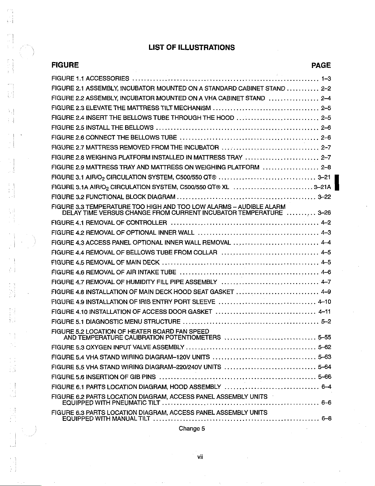
FIGURE
0.00.
..............
FIGURE
erent
FIGURE
7.3)
eens
리 리 리 이 이 리 아 리 기 아 리 이 아 이 기 이
7.4)
1...
5.1.
7.5)
cece cece
이 기 사 시 아 기 이 이 가 기 기 이 기 이 시
cece
engen
ee
nee
tenet
기 사
ee
teeter
시 아 기 이시기에
..
ee
te
tenees
시게 세 세이야
nk
PAGE
...
...
..
...
ÓN
아가
..
..
..
...
3-23
3-23
3-27
3-27
3-27
3-27
3-27
3-27
327
3-27
3-28
3-28
3-28
SERIAL
A/D
SUPPLY
INTERNAL
DATA
05732
TEMPERATURE
HYBRIDS
PROBES
AUXILARY
DUAL
DISPLAY
НЕАТЕВ
SERIAL
МУЕТ--РУАРОЗЕ
ALARM
GENERAL
ALARMS..........................
COMMUNICATIONS
CONVERTER
VOLTAGE
OPERATION
BUS
PERIPHERALS
INPUTS
..............
----υ--υ--ι
TEMPERATURE
AIR
BOARD
ВОАЛО............
COMMUNICATIONS
LOGIC
TIMING
.
...........
.............
MODES
......
чении
..............
....
...ocococcoconooorcnrnn
ООЧТРОТ
.
........
..
ии
еее
тии
неее
SS
LK
ни
аня
KK K K K
иена
ii
rro
нити
тина
nr
rr
nro
nr
narran
ея и ниче
P K K S K K K K K KK
K
очен
K
nan
rra
rre
0
сне
нина
sn
가
net
TABLE
OF
CONTENTS
(continued)
SECTION
5.4.7
ACCESSING
5.4.8
ACCESSING
5.5
TEST
AND
CALIBRATION
5.5.1
GENERAL
5.5.2
TEST
EQUIPMENT
5.5.4
FAN
SPEED
FAN
SPEED
AC
LINE
TEST
TEST
SET-UP
PROCEDURE
5.5.5
LEAKAGE
TEST
SET-UP
PROCEDURE
5.5.6
OXYGEN
TEST
SET-UP
PROCEDURE
5.71GENERAL..................
5.7.2
CONTROLLER
PRINTED
CONTROLLER
DISPLAY
MAINPRINTEDCİRCUITBOARD
IMPELLERFANMOTORANDAIRFLOWPROBE
AC
ENTAY
AIR
TEMPERATURE
HEATER
A
POWER
5.7.3
PNEUMATIC
5.7.4
OXYGEN
5.7.5
VHA
STAND
VHA
STAND
UP/DOWN
PHASE
5.7.6
OUTER
SHIFT
REASSEMBLY
THE
THE
....................
AND
CALIBRATION
MONITORING
POINT
CIRCUIT
BOARD
BOARD
иены,
SUPPLY
COLUMN
AND
Lei
.................
CURRENT
..................
CONCENTRATIONTESTS
FRONT
FRONT
................
BOARD
................
..............
FRONT
INPUT
SWITCH
VALVE
...............
ACTUATOR
CAPACITOR
OF
(REFER
CONTROLLER
CONTROLLER
REQUIRED
AC
LINE
MONITORING
(REFER
CALIBRATION
ADJUSTMENT
TESTS
PANEL
BOARDS
PANEL
AND
CHASSISRIGHTSIDEPANEL
PROBE
PANEL
FILTER
.....
..........
INNER
COLUMN
TO
CLEAR
MEMORY
..
TO
..
AND
....
.................
CARTRIDGE
FIGURE
DIAGNOSTIC
AVAILABLE
CALIBRATION
FIGURE
(REFER
LOCATIONS)
ани
CONTROLLER
INTO
5.6)
5. 2 FOR
TO
eee
eet
азии
.................................
...............,..........,.,.........2.
LOG
MENU
MENU
ADJUSTMENT
FIGURE
5. 2 FOR
ee
ини
аи и ип
........................
°
.................
...
rr
ee
LOCATION)
неитетнаннй
ekk
n
n
k
PAGE
5-37
5-54
..
5-54
5-60
5-60
5-65
SECTION
PARTS
6.1
GENERAL
E
6.2
RECOMMENDED
SECTION
DIAGRAMS
7.1GENERAL
6
LIST
..............
..
7
.....
SPARE
DE
0000000000000
еее
PARTS — OUANTITY
енко
Change
ee
0 R R
еее
OF 1 TO 5 UNITS
R
SK K K K KOLO
6
KOS K PRA
ké
RKO K KOK
OKEM S KS
KS K SEO
KK
OK
nK
nn
ne
7-1
7-1
TABLE
LIST
OF
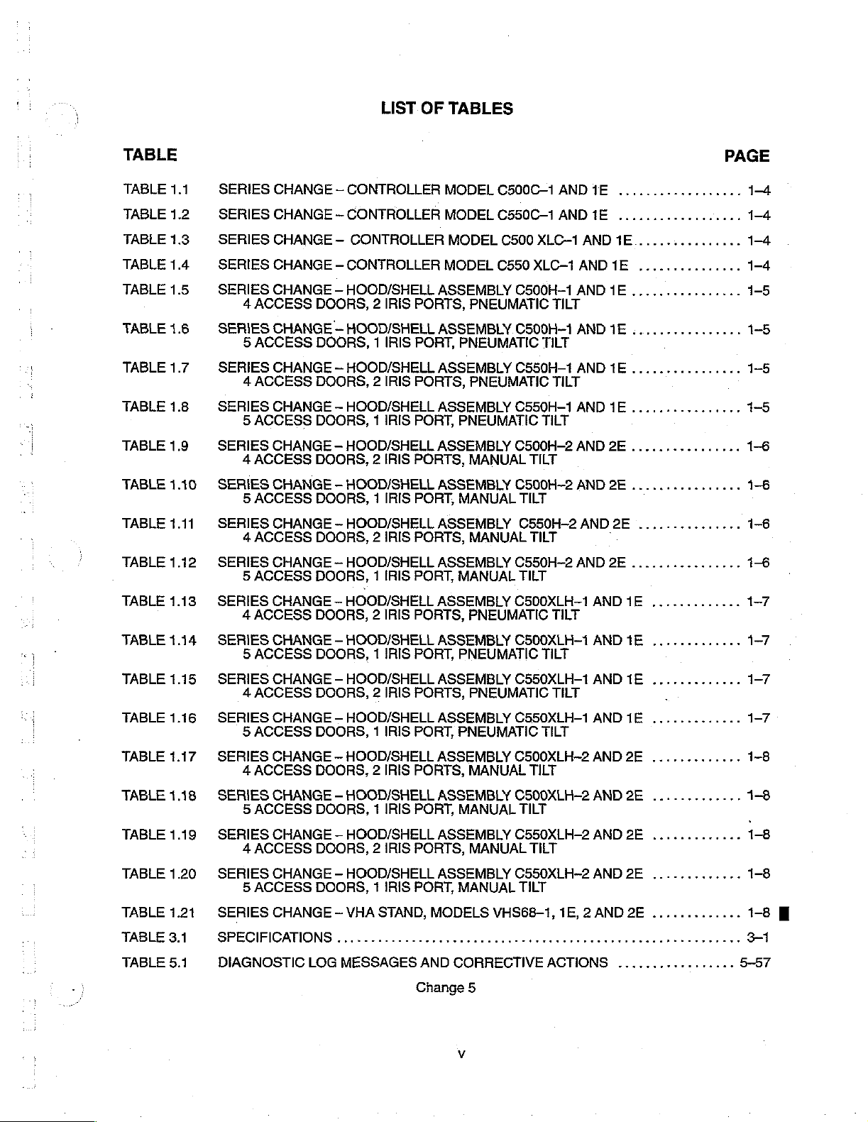
TABLES
TABLE
TABLE
TABLE
TABLE
TABLE
TABLE
TABLE
TABLE
TABLE
TABLE
TABLE
TABLE
1.1
1.2
1.3
1.4
1.5
1.6
1.7
1.8
1.9
1.10
1.11
1.12
SERIES
SERIES
SERIES
SERIES
SERIES
4
ACCESS
SERIES
5
ACCESS
SERIES
4
ACCESS
SERIES
5
ACCESS
SERIES
4
ACCESS
SERIES
5
ACCESS
SERIES
4
ACCESS
SERIES
5
ACCESS
CHANGE - CONTROLLER
CHANGE — CONTROLLER
CHANGE - CONTROLLER
CHANGE — CONTROLLER
CHANGE - HOOD/SHELL
CHANGE — HOOD/SHELL
CHANGE - HOOD/SHELL
CHANGE — HOOD/SHELL
CHANGE — HOOD/SHELL
CHANGE - HOOD/SHELL
CHANGE - HOOD/SHELL
CHANGE — HOOD/SHELL
DOORS, 2 IRIS
DOORS, 1 IRIS
DOORS, 2 IRIS
DOORS, 1 IRIS
DOORS, 2 IRIS
DOORS, 1 IRIS
DOORS, 2 IRIS
DOORS, 1 IRIS
PORTS,
PORT,
PORTS,
PORT,
PORTS,
PORT,
PORTS,
PORT,
MODEL
MODEL
MODEL
MODEL
ASSEMBLY
PNEUMATIC
ASSEMBLY
PNEUMATIC
ASSEMBLY
PNEUMATIC
ASSEMBLY
PNEUMATIC
ASSEMBLY
MANUAL
ASSEMBLY
MANUAL
ASSEMBLY
MANUAL
ASSEMBLY
MANUAL
C500C—1
C550C—1
C500
XLC-1
C550
XLC-1
C500H-1
TILT
C500H-1
TILT
C550H-1
TILT
C550H-1
TILT
C500H-2 AND
TILT
C500H-2
TILT
C550H-2
TILT
C550H-2 AND
TILT
AND
AND
1E
1E
AND
1E................
AND
1E
...............
AND
1E
................
AND
1E
................
AND
1E
................
AND
1E
................
2E
................
AND
2E
................
AND
2E
...............
-
2E
................
14
1-4
1-5
1-5
1-5
1-5
1-6
1-6
1-6
16
TABLE
TABLE
TABLE
TABLE
TABLE
TABLE
TABLE
TABLE
TABLE
TABLE
TABLE
1.13
1.14
1.15
1.16
1.17
1.18
1.19
1.20
1.21
3.1
5.1
SERIES
SERIES
SERIES
SERIES
SERIES
SERIES
SERIES
SERIES
SERIES
SPECİFICAMONS......................
DIAGNOSTIC
CHANGE — HOOD/SHELL
4
ACCESS
CHANGE - HOOD/SHELL
5
ACCESS
CHANGE — HOOD/SHELL
4
ACCESS
CHANGE — HOOD/SHELL
5
ACCESS
CHANGE — HOOD/SHELL
4
ACCESS
CHANGE — HOOD/SHELL
5
ACCESS
CHANGE - HOOD/SHELL
4
ACCESS
CHANGE — HOOD/SHELL
5
ACCESS
CHANGE - VHA
DOORS, 2 IRIS
DOORS, 1 IRIS
DOORS, 2 IRIS
DOORS, 1 IRIS
DOORS, 2 IRIS
DOORS, 1 IRIS
DOORS, 2 IRIS
DOORS, 1 IRIS
LOG
MESSAGES
PORTS,
PORT,
PORTS,
PORT,
PORTS,
PORT,
PORTS,
PORT,
STAND,
ASSEMBLY
ASSEMBLY
ASSEMBLY
ASSEMBLY
ASSEMBLY
ASSEMBLY
ASSEMBLY
ASSEMBLY
MODELS
AND
Change
PNEUMATIC
PNEUMATIC
MANUAL
MANUAL
CORRECTIVE
PNEUMATIC
C500XLH-1
C500XLH-1
C550XLH-1
PNEUMATIC
C550XLH-1
C500XLH-2
MANUAL
C500XLH-2
TILT
C550XLH-2
MANUAL
C550XLH-2
TILT
VHS68-1,
яние
5
TILT
TILT
TILT
TILT
TILT
TILT
ACTIONS
AND
AND
AND
AND
AND
AND
AND
AND
1E, 2 AND
тик
1E
.............
1E
.............
1E
.............
.
1E
.............
2E
.............
2E
.............
2E
.............
2E
.............
2E
.............
K K K
......,..........
1-7
1-7
1-7
1-7
1-8
1-8
1-8
1-8
1-8
3—
5-57
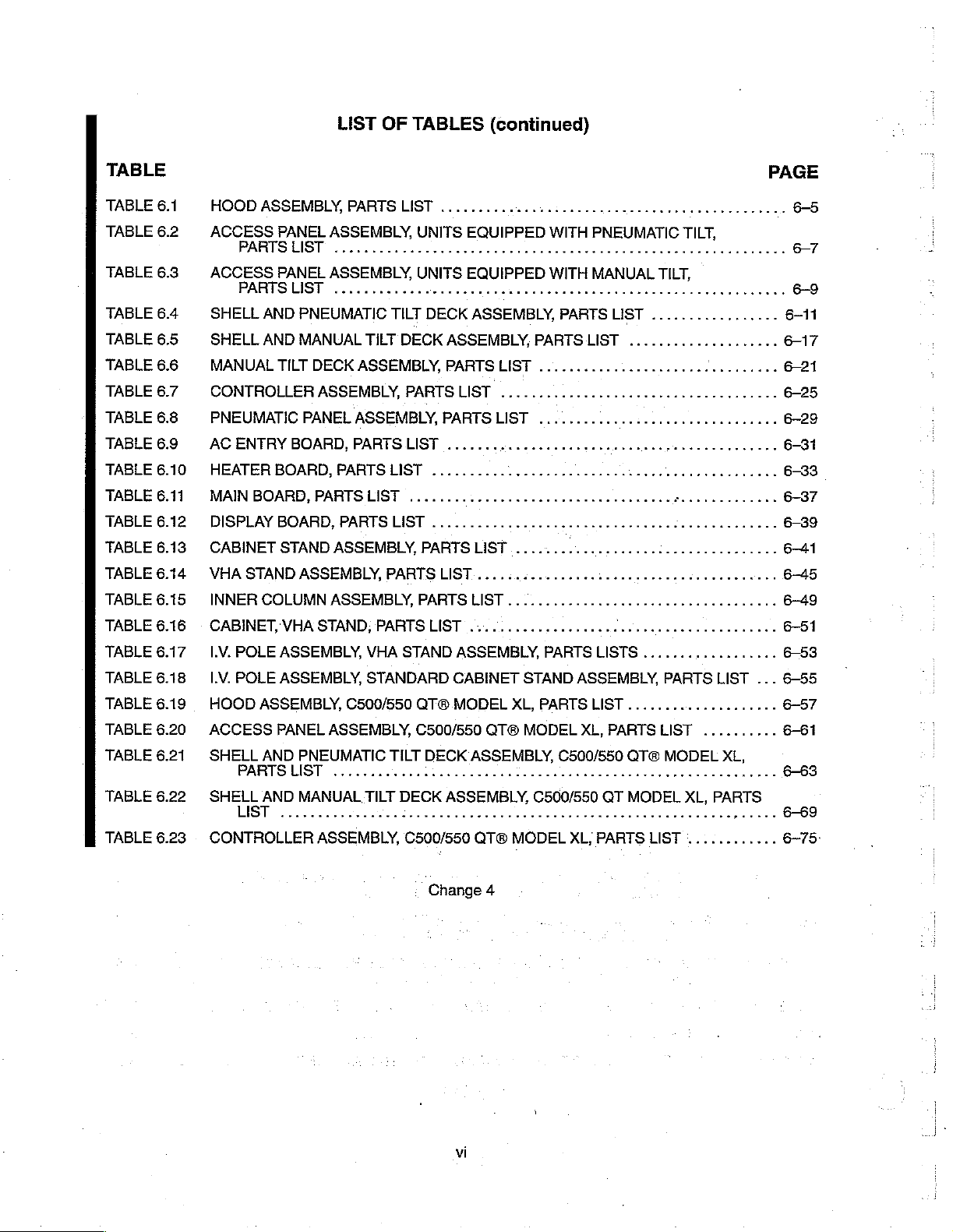
LIST
OF
TABLES
(continued)
TABLE
TABLE
TABLE
TABLE
TABLE
TABLE
TABLE
TABLE
TABLE
TABLE
TABLE
TABLE
TABLE
TABLE
TABLE
TABLE
TABLE
TABLE
TABLE
TABLE
TABLE
TABLE
TABLE
TABLE
6.1
6.2
6.3
6.4
6.5
6.6
6.7
6.8
6.9
6.10
6.11
6.12
6.13
6.14
6.15
6.16
6.17
6.18
6.19
6.20
6.21
6.22
6.23
HOOD
ACCESS
ACCESS
SHELL
SHELL
MANUAL
CONTROLLER
PNEUMATIC
AC
HEATER
MAIN
DISPLAY
CABINET
VHA
INNER
CABINET,
LV.
IV.
HOOD
ACCESS
SHELL
SHELL
CONTROLLER
ASSEMBLY,
PANEL
PARTS
PANEL
PARTS
AND
AND
TILT
ENTRY
BOARD,
BOARBP,
BOARD,
STAND
STAND
COLUMN
POLE
ASSEMBLY,
POLE
ASSEMBLY,
ASSEMBLY,
PANEL
AND
PARTSLUIST
AND
LIST
PARTS
ASSEMBLY,
LIST
ASSEMBLY,
LIST
PNEUMATIC
MANUAL
DECK
ASSEMBLY,
PANEL
BOARD,
ASSEMBİY,
VHASTAND,FARTSLIST
PNEUMATIC
MANUAL
ASSEMBLY,
PARTSLIST
PARTS
PARTS
PARTSLIST
ASSEMBLY,
ASSEMBLY,
C500/550
ASSEMBLY,
............1......
iii
ASSEMBLY,
LIST
cee
TILT
TILT
DECK
ASSEMBLY,
PARTS
LIST
LIST
PARTSLIST...............
VHA
STAND
STANDARD
ATB
C500/550
TILT
TILT
DECK
iii
C500/550
ен
UNITS
UNITS
PARTS
EQUIPPED
EOUIPPED
ce
cence
eect
DECK
ASSEMBLY,
ASSEMBLY,
PARTSUIST
LIST
PARTS
......
..........
....................
PARTSLIST...................
LIST
....................
ASSEMBLY,
CABINET
MODEL
QT®
DECK
ASSEMBLY,
1
ASSEMBLY,
rei
QT®
PARTS
......................
LIST
2000000000000
чении
rr
.............,..,..,...,....
PARTS
STAND
XL,
PARTS
MODEL
C500/550
MODEL
неее
WITH
PNEUMATIC
WITH
MANUAL
PARTS
LIST
ρε
1...
LISTS
ASSEMBLY,
LIST
XL,
C500/550
te
teeter
XL,
PARTS
K
LIST
нение
ννωκεω
laaan
PARTS
QTO
QT
MODEL
PAGE
ини
ен
няни
ee
TILT,
rae
TILT,
.................
....................
rr
νε ὁ 00000
eee
0...
..................
PARTS
....................
LIST
MODEL
n
LIST
ene
een
eae
nee
k
0...
아아
LIST
...
..........
XL,
eres
XL,
PARTS
K
Ke
............
6-5
677
6-55
6-57
6-61
6-63
6-69
6-75
Change
vi
4

TABLE
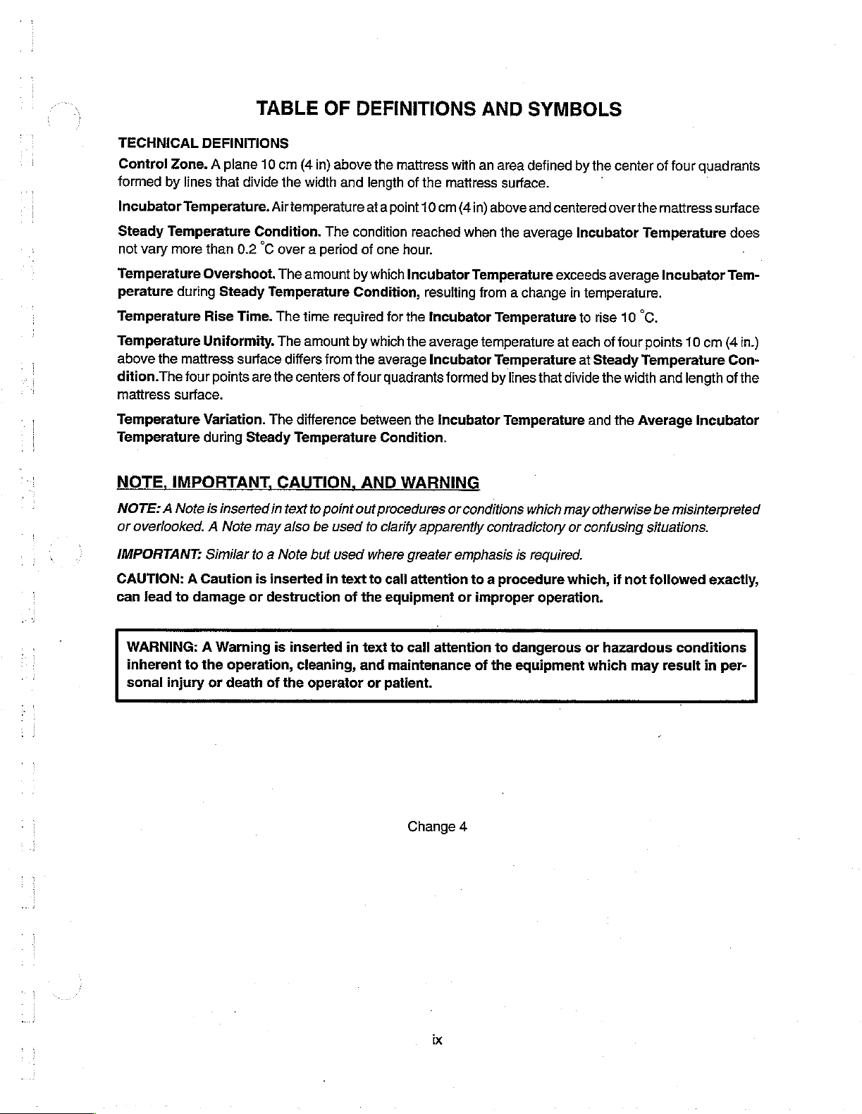
OF
DEFINITIONS
AND
SYMBOLS
TECHNICAL
Control
formed
Incubator
Steady
not
vary
Temperature
perature
Temperature
Temperature
above
the
dition.The
mattress
Temperature
Temperature
NOTE,
NOTE: A Note
or
overlooked. A Note
DEFINITIONS
Zone. A plane
by
lines
Temperature.
Temperature
more
than
Overshoot.
during
Rise
Uniformity. The
mattress
four
points
surface.
Variation.
during
IMPORTANT,
is
that
divide
Condition.
0.2
Steady
Time.
surface
are the
Steady
inserted
may
10
cm
(4
in)
the
width
Airtemperature
The
°C
over a period
The
amount
Temperature
The
time
amount
differs
from
centers
The
difference
Temperature
CAUTION,
in
text
to
point
also
be
used
above
the
and
length
at a
condition
of
one
by
which
Condition,
required
by
which
the
average
of
four
between
Condition.
AND
out
procedures
io
clarify
mattress
of
the
point 10
reached
hour.
Incubator
resulting
for
the
Incubator
the
average
Incubator
quadrants
the
WARNING
apparently
with
an
maitress
cm
(4
in)
when
Temperature
from a change
temperature
formed
Incubator
or
conditions
contradictory
area
defined
surface.
above
and
centered
the
average
exceeds
Temperature
at
Temperature
by
lines
that
Temperature
which
by
the
center
overthe
Incubator
average
in
temperature.
to
rise
each
of
at
Steady
divide
the
and
the
may
otherwise
or
confusing
of
mattress
Temperature
Incubator
10
°C.
four
points
Temperature
width
and
Average
be
situations.
four
quadrants
surface
does
・
Tem-
10
cm
(4
in.)
Con-
length
of
the
Incubator
misinterpreted
IMPORTANT:
CAUTION: A Cauiion
can
lead
to
damage
Similar
WARNING: A Warning
inherent
sonal
to
the
injury
operation,
or
death
to a Note
is
inserted
or
destruction
is
inserted
cleaning,
of
the
but
used
in
text
of
in
operator
where
to
call
the
equipment
text
to
and
maintenance
or
patient.
greater
attention
call
Change
emphasis
attention
is
to a procedure
or
improper
to
dangerous
of
the
equipment
4
required.
which,
operation.
or
which
if
not
followed
hazardous
may
result
exactly,
conditions
in
per-
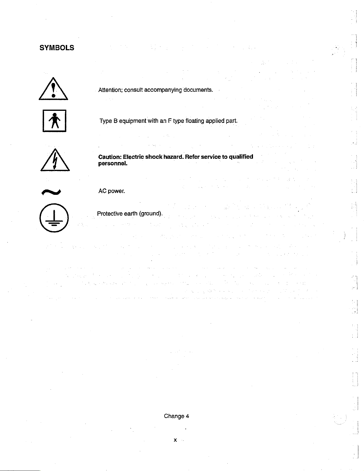
SYMBOLS
Attention;
Type B equipment
consult
accompanying
with
an F type
documents.
floating
applied
part.
BP
Caution:
personnel.
Electric
shock
hazard.
Refer
service
to
qualified
P
AC
power.
Protective
earth
(ground),
(Di
Change
4
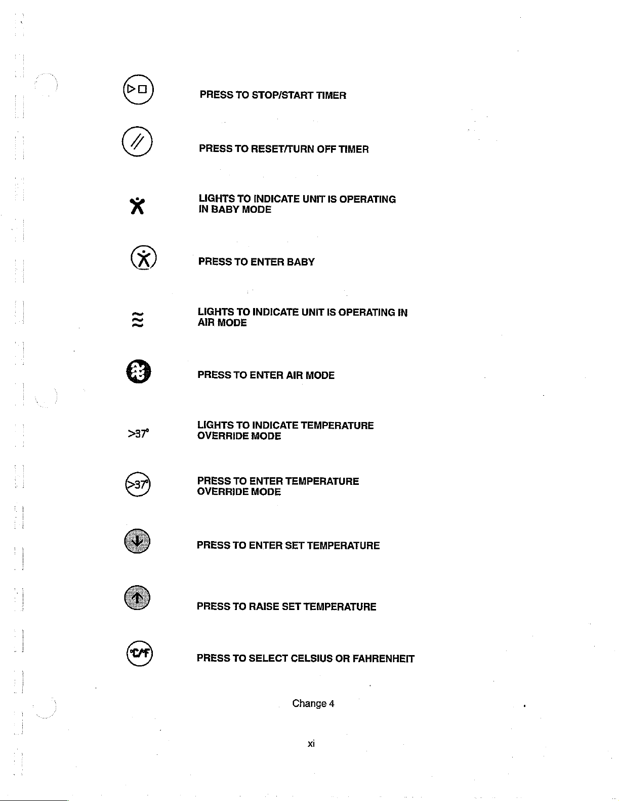
PRESS
TO
STOP/START
TIMER
PRESS
LIGHTS
IN
BABY
PRESS
TO
LIGHTS
AIR
MODE
PRESS
TO
LIGHTS
OVERRIDE
TO
RESET/TURN
TO
INDICATE
MODE
ENTER
TO
INDICATE
ENTER
TO
INDICATE
MODE
OFF
UNIT
BABY
UNIT
AIR
MODE
TEMPERATURE
TIMER
IS
OPERATING
IS
OPERATING
IN
PRESS
TO
OVERRIDE
PRESS
PRESS
PRESS
TO
TO
TO
ENTER
MODE
ENTER
RAISE
SELECT
TEMPERATURE
SET
TEMPERATURE
SET
TEMPERATURE
CELSIUS
Change
4
xi
OR
FAHRENHEIT
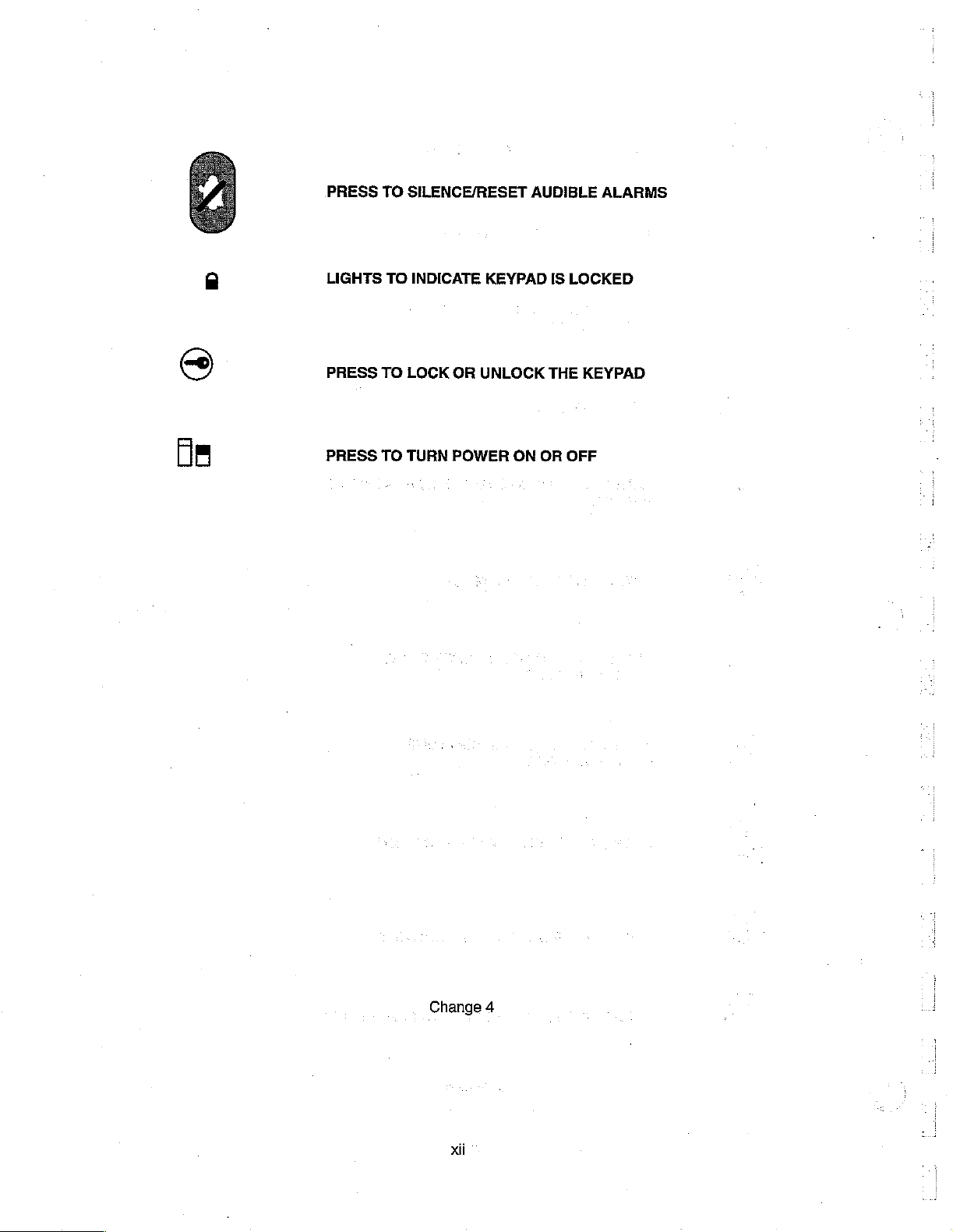
PRESS
TO
SILENCE/RESET
AUDIBLE
ALARMS
dm
LIGHTS
PRESS
PRESS
TO
TO
TO
TURN
INDICATE
LOCK
OR
POWER
KEYPAD
UNLOCK
ON
IS
THE
OR
LOCKED
KEYPAD
OFF
Change
xii
4
GENERAL
C500/C550
INFORMATION
1.1
INTRODUCTION
This
manual
Models
This
equipment
1.2
1.2.1
The
Temperature
C500
manual
are
DESCRIPTION
ISOLETTE®
Isolette®
panel.
1.2.2
ISOLETTE®
The
Isolette®
Temperature
panel.
In
addition,
infants
selected
it
temperature
by
the
provides
QT®
is
intended
Infant
Override
Infant
Override
provides a sensing
instructions
and
provided
INFANT
Incubator,
INFANT
Incubator,
can
Baby
Set
C550
for
use
in a separate
INCUBATOR,
Mode)
INCUBATOR,
Mode)
be
controlled
Temperature
GENERAL
for
installation,
QT®
and
C500
only
by
trained,
operator’s
Model
C500,
as
selected
Model C550,
as
selected
probe
which
from
Up/Down
SECTION
INFORMATION
maintenance
QT®
and
qualified
manual.
MODEL
provides
by
the
Air
MODEL
provides
by
the
Air
can
be
attached
34
to
37
Arrow
1
and
repair
C550
QT®
Model
service
C500
air
Set
C550
air
Set
°C
personnel.
temperature
Temperature
temperature
Temperature Up/Down
directly
(37
keys
to
on
38
the
to
°C
of
the
XL.
instructions
control
control
from
Up/Down
fron
the
infant's
in
Temperature
front
panel.
Isolette®
20
20
for
to
37
Arrow
to
37
Infant
the
keys
Arrow
skin.
Using
Override
Incubators,
operator
°C
(37
on
"C
(37
keys
on
this
of
to
39
“Cin
the
front
to
39
“Cin
the
front
probe,
Mode)
the
the
as
1.3
ACCESSORIES
Accessories
Part
Numbers,
*
Cabinet
e
Guard
Rail
e
Rail
System
e
SOLAIR™
e
MICRO-~LITE™
9
DEW-ETTE®
e
WARM
e
Remote
e
VHA
e
Rail
e
Monitor
e
Inner
e | ATHENA
WEIGH
(Vertical
System
Walls
available
Additional
Stand
for
Standard
Transparent
Phototherapy
Incubator
Alarm
Module
Height
for
VHA
Shelf
Package
(refer
Shelf
Assembly
forthe
C500/C550
Accessories, a list
Cabinet
Hood
Warmer
System
Humidifier
infant
Scale,
Model
Adjustable)
Stand
to
Figure
4.2)
QT®
Stand
(Not
Stand
are
listed
below
of
operator-replaceable
Shown)
120
and
illustrated
parts
in
Figure
and
1.1.
single
Referto
use
items.
Section6,
Change
4

C500/C550
GENERAL
©
ATHENA®
e
Utility
e
IV
Tree
e
Ventilator
©
Oxygen
e
Air
Flow
e
Suction
e
Blender
e
MICRO-LITE™
INFORMATION
PAM
Mounting
Pole
Assembly
Assembly
Mounting
Flowmeter
Kit
Kit
Kit
Pivot
Pole
Kit
Arm
Kit
Assembly
Change
4
 Loading...