

Air-Shields C400QT, C450QT User manual
DE
1
3
ETTE
S
C400
®
|NFANT
QT
AND
INCUBATORS
C450
OT
e
PRELIMINARY
SERVICE
Air-ShieldsW/
vær
MANUAL
The
product
year
from
Ail
consumable
Calibrations
During
customer.
This
This
for
from
“The
least
Testing
cians
the
warranty
1.
N
RO
warranty
incidental
breach
Accreditation
annually
Compliance
through
being
the
warranty
There
Damage
The
customer
The
customer
Sale
or
is
or
of
thereafter.
our
described
date
of
shipment
and
disposable
are
considered
period
will
be
no
is
rendered
to
service
in
lieu
consequential
warranty.
Manual
Product
void
the
unit
fails
uses
is
performed
of
all
for
To
Program
Service
in
this
frorn
normal
any
defective
labor
charge
and
is
incurred
to
maintain
any
parts,
other
warranties,
damages
Hospitals
comply
during
LIMITED
WARRANTY
manual
Air-Shields,
products
Air-Shields
by
with
the
Group
is
warranted
Hatboro,
are
guaranteed
maintenance
parts
other
than
for
replacing
cannot
as
a
result
of
the
unit
in
a
accessories,
a
non-certified
expressed
including
requires
this
standard,
warranty
and
loss
each
period.
authorized
against
with
the
to
and
are
not
those
listed
the
parts
within
be
held
liabie
mishandling.
proper
or
manner.
fittings
of
piece
we
not
service/dealer
or
implied,
use,
property
of
equipment
recommend
This
service
dealers.
defects
be
in
following
free
from
included
above
the
for
conditions
specified
agency.
and
Air—Shields
damage,
to
that
can
materials
exceptions.
defects
in
the
1
year
will
be
replaced
continental
resuitant
or
sold
by
shall
or
personal
be
tested
prior
you
participate
be
performed
or
workmanship
upon
shipment
warranty.”
at
no
charge
U.S.
therefrom
Air-Shields.
in
no
event
injury
to
initial
in
our
Accreditation
by
certified
for
one
only.
to
the
if:
be
liable
resulting
use
and
techni-
at
Please
Since
improvements
the
rear
on
shown
THIS
MODIFICATIONS
TO
CANNOT
OPERATION
OR
check
Air-Shields
printed
each
MAINTAIN
MODIFICATION.
of
the
page
on
MANUAL
manuals.
manual
the
ASSUME
OF THIS
NOTE
Some
parts
used
this
manual.
function
of
This
the
PLEASE
the A page
conducts a continuous
are
sometimes
or
of
text
right.
CONTAINS
SHOULD
YOUR
in
sometimes
equipment.
for
change
incorporated
When
this
under
separate
is
indicated
PROPRIETARY
BE
WARRANTY
RESPONSIBILITY
EQUIPMENT
ON
your
REPLACEMENT
equipment
occurs
Order
information.
product
occurs,
by a vertical
PERFORMED
changed
cover
AND
FOR ANY
WHICH
may
be
due
to
the part
listed
READ
improvement
into
equipment
material
in
the
form
bar
in
the
INFORMATION.
ONLY
TO
AVOID
CONDITIONS
MAY
RESULT
different
difficulty
in
than
in
the
program,
before
is
provided
of a change
margin
BY
CREATING
parts
Parts
next
REPAIRS
QUALIFIED
FROM
those
which
procurement,
List.
circuit
they
can
be
on
separate
package.
to
the
SAFETY
AFFECTING
UNAUTHORIZED
Changed
changed
AND
SERVICE
PARTS
appear
but
and
component
incorporated
sheets
material
material,
AUTHORIZED
PERSONNEL
HAZARDS.
THE
PROPER
REPAIR
in
the
Parts
does
not
alter
into
at
the
WE
List
the
as
of
For
optimal
Service
required
tory—authonzed
AT.
1
23456789
123456789
NO.
Group
maintenance
68
performance,
instrumentation
Air—Shields’
Air-Shields
994
50-A
product
specialists
by
calling
330
800-523-2404.
distributor
Jacksonville
service
for
SERVICE
should
be
are
located
Customers
service.
Road,
performed
throughout
outside
Hatboro,
only
the
V
by
qualified
United
the
U.S.
service
States
should
personnel.
and
are
contact
Vickers
medical
PA
19040
Printed
Product
dispatched
their
local
in
USA
for
fac-
10/94
NOTE:
ALSO
SEE
PAGE
2.
LIST
OF
EFFECTIVE
PAGES
THERE
ARE
NO
MODIFICATIONS
AVAILABLE.
PAGE
Front
Cover
Inside
Front
1
と
AandB
ithrough
1
των
2-1
through
St
through
4-1
through
5-1
through
6-1
through
7-4
through
NO.
....................,..........
Cover
..........................
......................,...........
ον ον
ενω
..............................
.
...................,...........
...................,......,....
...............................
...................,......,....
ε
ον
ω
νε
νεο
νε εν
νε
εννοω
CHANGE
ρε ε ο ο ο
νέων
NO.
0
O
0
(O
k
0
0
νο
0
(O
eee
ων
0
[
0
D..............,....,......,....,.2.
0
ενω
ωρών
ων
ее
εννοω
κε
нение
eres
εοωω
ων
εν εν ν εν
εως
DATE
nseene
vnnne
ών
νο
νο
кинзьния
εν νε
OF
10/94
10/94
10/94
10/94
10/94
10/94
10/94
10/94
10/94
10/94
10/94
10/94
10/94
ISSUE
ee
σος,
-
—Ct1w1w1r
———L>Ò>>>ETEI=——-—-——=-r=<-—-=—<-5"!#F8
NeNNN!II
——_
8
TECHNICAL
Control
by
Incubator
face.
Steady
not
Temperature
perature
Temperature
Temperature
above
dition.
mattress
Zone. A plane
lines
that
Temperature
vary
more
during
the
mattress
The
surface.
Temperature.
DEFINITIONS
divide
the
than
0.2
Overshoot.
Steady
Rise
Time.
Uniformity.
surface
four
points
ISOLETTEs
TABLE
10
cm
width
Air
Condition.
°C
over a period
The
Temperature
The
The
are
the
OF
above
the
and
length
temperature
The
amount
time
required
amount
differs
from
centers
of
DEFINITIONS
mattress
of
condition
of
by
Condition,
by
the
four
Infant
with
the
mattress
at a point
reached
one
hour.
which
Incubator
for
the
which
the
average
quadrants
AND
an
area
surface.
10
cm
(4
in.)
when
Temperature
resulting
Incubator
average
Incubator
temperature
formed
Incubator
SYMBOLS
defined
from a change
Temperature
by
by
the
above
and
the
average
exceeds
Temperature
at
lines
that
center
centered
tncubator
in
to
each
at
divide
of
four
quadrants
over
the
Temperature
average
temperature.
rise
of
four
Steady
the
Incubator
11
°C.
points
Temperature
width
and
formed
mattress
does
Tem-
10
cm
(4
Con-
length
of
sur-
in.)
the
(This
page
is
intentionally
lett
blank.)
Temperature
Temperature
Variation.
during
Steady
The
difference
Temperature
between
Condition.
the
Incubator
Temperature
and
the
Average
Incubator
C400/C450
GENERAL
INFORMATION
1.1
INTRODUCTION
This
manual
Models
This
manual
the
equipment
1.2
DESCRIPTION
The
forced
distribution,
oxygen
Entry
Ports.
mattress
the
hood
operating
Baby
or
for
air
heater
feature.
provides
C400
is
air
humidification,
concentrations.
When
toward
environment.
temperature
Air
Temperature
temperature
output,
The
Models
GENERAL
instructions
QT®
and
C450
intended
are
for
provided
circulation
Accessibility
the
Access
the
top
of
the
The
range
Control
control.
and a comprehensive
C400
QT®
for
QT®.
use
only
in a separate
system
effective
Panel
Access
Incubator
of
20
is
Instrumentation
and
SECTION
installation,
by
trained,
operator's
of
the
Incubator
isolation
to
the
infant
is
open, a curtain
Panel
opening;
is
designed
to
30
°C. A guard
seiected
visual
C450
by a front
includes
QT®
INFORMATION
maintenance
qualified
of
is
for
and
Incubators
manual.
permits
the
infant
provided
of
this
use
rail
panei
digital
audible
service
warm
air
in a nursery
is
standard
control.
1
and
personnel.
stable
from
by an
air
curtain
display
alarm
also
include
repair
of
temperature
airborne
Access
flows
from
minimizes
environment
on
all
units.
The
Model
for
temperature,
system
the
the
Isolette®
Instructions
for
control,
contaminants,
Panel,
which
Access
beneath
the
C400
the
temperature
having a typical
On
the
QT®
relative
includes
following
features:
Model
Infant
the
uniform
and
Doors,
front
edge
C450
is
equipped
indication
an
Incubators,
operator
of
heat
control
drop
and
Iris
of
the
within
ambient
of
QT®,
only
of
alarm
test
»
Oval
Access
e
The
Mattress
‧
Optional
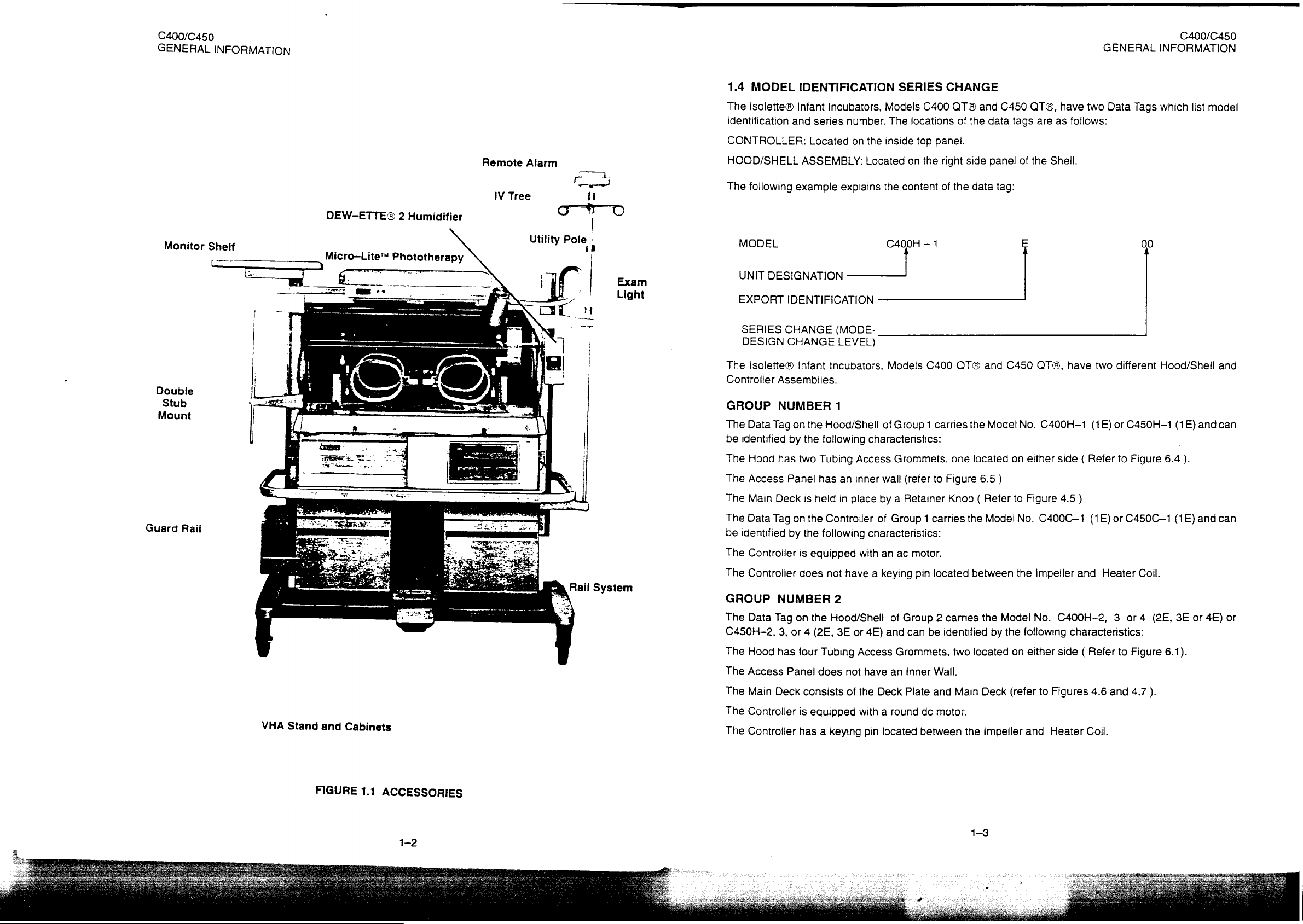
1.3
ACCESSORIES
Accessories
manual
+
+
e
+
*
9
e
e
e
©
e
e
9
e
e
for
part
Cabinet
Guard
Rail
VHA
Rail
Rail
System
(Vertical
System
SOLAIR™
MICRO-LITE™
DEW-ETTE®
Remote
WARM
Monitor
ATHENA®
ATHENA®
Utility
Pole
LV.
Tree
Doors
Tilt
VHA
Stand
available
numbers.
Stand
Standard
Height
for
VHA
Transparent
Phototherapy
2
Alarm
WEIGH
Shelf
Module
Package
Shelf
PAM
Assembly
Assembly
with a Quiet
Mechanism
for
use
Cabinet
Adjustable
Stand
Hood
Incubator
Infant
Scale,
Assembly
Mounting
Latch
continuously
with
the
Incubators
Stand
Stand)
Warmer
System
Humidifier
Model
Kit
(Not
Shown)
(Not
120
variable
are
Shown)
(Refer
to
from
0°
to
9°
illustrated
e
e
e
e
Figure
in
Oxygen
Air
Flow
Suction
Blender
2.5)
from
either
Figure
Flowmeter
Kit
(Not
Kit
(Not
Kit
(Not
1.1.
Shown)
Shown)
Shown)
end
Refer
Kit
to
Section 6 of
(Not
Shown)
this
C400/C450
GENERAL
Monitor
INFORMATION
Sheif
|
Kk 一 一 一 一
=-
fx
a
一 一 一 一
DEW-ETTE®
Micro—Lite™
E
2
,
Humidifier
Phototherapy
Remote
IV
Tree
Alarm
2
Utility
[ren]
11
Pole,
|
|
i
C400/C450
1.4
MODEL
The
Isolette®
identification
CONTROLLER:
and
HOOD/SHELL
IDENTIFICATION
Infant
Incubators,
series
Located
ASSEMBLY:
number.
on
the
Located
SERIES
Models
The
locations
inside
on
C400
top
the
CHANGE
ATA
of
panei.
right
and
the
side
C450
data
panel
tags
of
OTA,
are
the
have
as
follows:
Sheil.
GENERAL
two
Data
INFORMATION
Tags
which
list
model
그.
The
following
|
MODEL
example
explains
the
content
C400H - 1
of
the
data
tag:
00
|
UNIT
Exam
Light
DESIGNATION
EXPORT
SERIES
DESIGN
IDENTIFICATION
CHANGE
CHANGE
_
(MODE-
LEVEL)
|]
Double
Stub
Mount
Guard
Rail
ο
LA
Rail
System
The
Isolette®
Controller
GROUP
The
Data
be
identified
The
Hood
The
Access
The
Main
The
Data
be
identified
The
Controller
The
Controller
GROUP
The
Data
C450H-2,
The
Hood
The
Access
Infant
Assemblies.
NUMBER
Tag
on
the
by
the
has
two
Tubing
Panel
has
Deck
is
held
Tag
on
the
by
the
is
equipped
does
NUMBER
Tag
on
the
3,
or 4 (2E,
has
four
Panel
does
Incubators,
1
Hood/Shell
following
Access
an
inner
in
place
Controller
following
with
not
have a keying
2
Hood/Shell
3E
or
4E)
Tubing
Access
not
have
Models
of
characteristics:
C400
Group 1 carries
Grommets,
wall
(refer
to
by a Retainer
of
Group 1 carries
characteristics:
an
ac
motor.
pin
located
of
Group 2 carries
and
can
be
Grommets,
an
Inner
Wall.
OTA
and
the
Model
one
located
Figure
6.5
Knob ( Refer
the
Model
between
the
identified
two
by
located
C450 QT®,
No.
on
either
)
to
Figure
No.
the
impeller
Model
the
following
on
either
No.
have
two
different
C400H—1
side { Refer
C400C-—1
4.5
)
(1E)
and
(1E)
Heater
or
C450H—1
to
Figure
or
C450C—1
C400H-2, 3 or 4 (2E,
characteristics:
side ( Refer
to
Figure
Hood/Sheil
Coil.
(1E)
6.4
).
(1E)
3E
6.1).
and
and
or
4E)
and
can
can
or
VHA
Stand
and
Cabinets
FIGURE
1.1
ACCESSORIES
The
Main
The
Controller
The
Controller
Deck
consists
is
equipped
has a keying
of
the
Deck
with a round
pin
located
Plate
de
between
and
motor.
Main
the
Deck
(refer
impeller
and
to
Figures
Heater
4.6
and
Coil.
4.7
).
a
TAB
SERIES
C400/C450
GENERAL
TABLE
S
ERIES
00
TABLE
SERIES
00
00
LE
1.2
NO.
1.3
NO.
INFORMATION
1.
oe
SERIES
3,3E,4,
NO.
SERIES
SERIES
CHANGE
AND
DESCRIPTION
Original
CHANG
DESCRIPTION
Original
CHANGE-CONTROLLER
DESCRIPTION
Original
9
-
HOOD/SHELL
4E.
MODELS
Design
E-CONTROLLER
Design
Desi
sign
—
C450H-1,
AND
2E
ASSEMBLY,
AND
2E
ASSEMBLY,
1E,
ITEMS/ASSEMBLIES
ASSEMBLY,
ITEMS/ASSEMBLIES
ITEMS/ASSEMBLIES
MODELS
2,
2E,
MODELS
MODELS
3,3E,
None
—
None
—
None
—
C400H-1,
4,
ANDGE
AFFECTED
C400C-1,
AFFECTED
C450C-1,
AFFECT;
ED
1E,
1E,
1E,
©
2,
2
2
UNPACKING
2.1
Typically,
shipped
otherwise
2.2
CAUTION:
Instructions
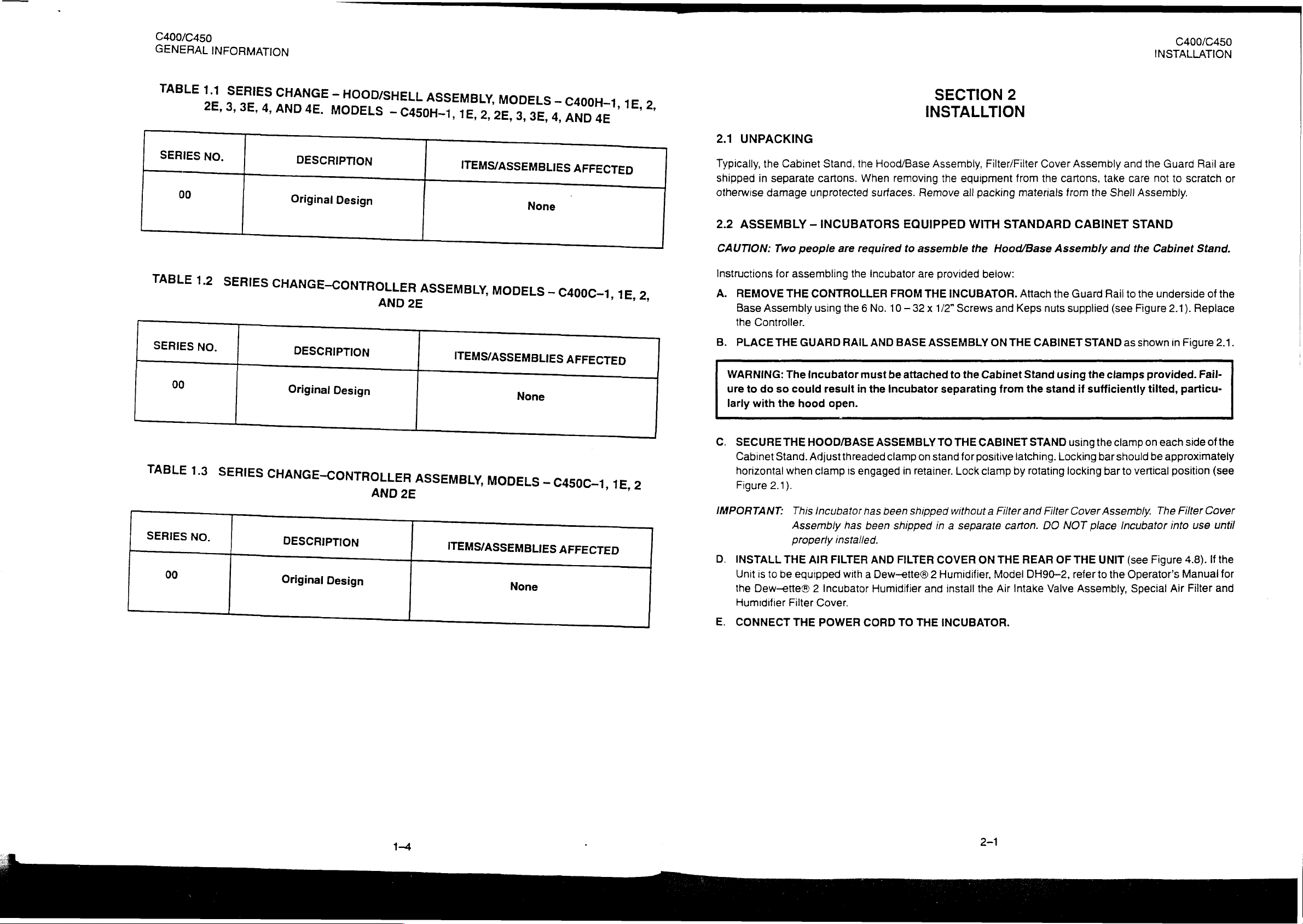
A.
B.
WARNING:
ure
larly
C.
IMPORTANT:
D.
E.
the
in
damage
ASSEMBLY
REMOVE
Base
Assembly
the
Controller.
PLACE
to
do
with
SECURE
Cabinet
horizontal
Figure
INSTALL
Unit
is
to
Dew-ette®
the
Humidifier
CONNECT
Cabinet
separate
Two
for
THE
THE
The
so
the
THE
Stand. Adjust
when
2.1).
THE
be
Filter
Stand,
cartons.
unprotected
—
INCUBATORS
people
assembling
CONTROLLER
using
GUARD
incubator must
could
result
hood
HOOD/BASE
clamp
This
Incubator
Assembly
Properly
AIR
equipped
Incubator
2
Cover.
THE
POWER
the
When
are
required
the
the
6
RAIL
in
open.
threaded
1s
engaged
has
installed
FILTER
with
Hood/Base
removing
surfaces.
Incubator
FROM
No.
10
AND
BASE
be
the
Incubator
ASSEMBLY
clamp
has
been
been
shipped
AND
FILTER
a
Dew—ette®
Humidifier
CORD
TO
SECTION
INSTALLTION
Assembly,
equipment
the
packing
Remove
EQUIPPED
to
assemble
are
THE
—
32 x 1/2”
ASSEMBLY
attached
on
in
retainer.
shipped
2
and
THE
all
WITH
the
provided
INCUBATOR.
Screws
to
the
Cabinet
separating
TO
THE
CABINET
stand
for
positive
Lock
clamp
without a Filter
in a separate
COVER
Humidifier,
INCUBATOR.
install
ON
the
2
Filter/Filter
STANDARD
Hood/Base
below:
and
ON
from
carton.
THE
Model
Air
Cover
the
from
materials
Attach
Keps
nuts
THE
CABINET
Stand
the
STAND
latching.
by
rotating
and
Filter
DO
REAR
DH90—2,
Intake
stand
Assembly
cartons,
from
CABINET
Assembly
the
Guard
supplied
using
using
Locking
locking
Cover
NOT
OF
THE
refer
Valve
and
care
take
Shell
the
and
Rail
to
(see
STAND
the
if
sufficiently
place
Assembly,
as
clamps
the
clamp
bar
should
bar
to
Assembly.
Incubator
UNIT
(see
to
the
Operator's
C400/C450
INSTALLATION
the
Guard
to
not
Assembly.
STAND
the
Cabinet
the
underside
Figure
vertical
Special
2.1).
shown
in
provided.
tilted,
on
each
be
approximately
position
The
into
Figure
Air
Figure
particu-
Filter
Manual
Rail
scratch
Stand.
of
Replace
2.1.
Fail-
side
of
(see
Cover
use
until
4.8).
If
:
and
Filter
are
or
the
the
the
for
1-4
C400/C450
INSTALLATION
Screw,
Nut,
10 — 32 x 1/2”
Keps,
10 — 32
(6)
(6)
ie
iii.
99
99
042
107
01
36
2.2
ASSEMBLY
STAND
CAUTION:
CAUTION:
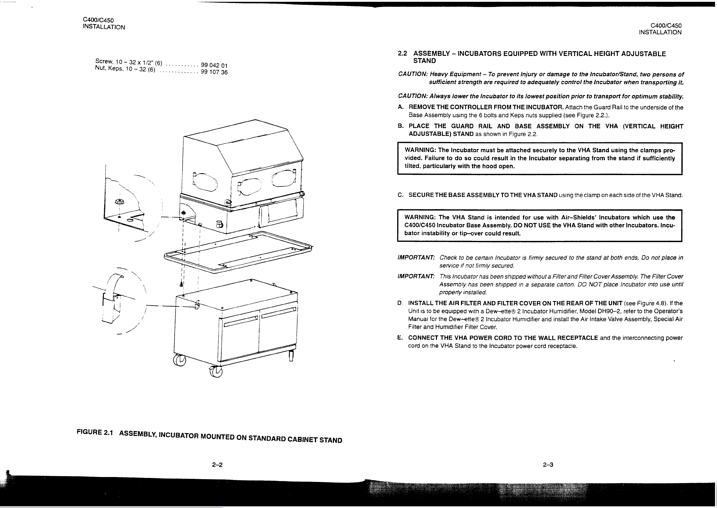
A.
REMOVE
Base
B.
PLACE
ADJUSTABLE)
WARNING:
vided.
tilted,
—
Heavy
sufficient
Always
Assembly
Failure
particularly
Equipment - To
lower
THE
CONTROLLER
using
THE
GUARD
STAND
The
Incubator
to
do
INCUBATORS
strength
so
with
are
the
Incubator
the 6 bolts
RAIL
as
shown
must
could
the
hood
EQUIPPED
prevent
required
to
FROM
and
Keps
AND
in
Figure
be
attached
result
in
open.
Injury
to
its
lowest
THE
INCUBATOR.
nuts
BASE
the
WITH
or
damage
adequately
position
supplied
ASSEMBLY
2.2.
securely
incubator
VERTICAL
to
the
control
(see
to
separating
prior
Attach
Figure
ON
the
VHA
the
HEIGHT
Incubator/Stand,
incubator
to
transport
the
Guard
2.2.).
THE
Stand
from
ADJUSTABLE
Rail
VHA
using
the
stand
when
for
to
(VERTICAL
C400/C450
INSTALLATION
two
persons
transporting
optimum
the
underside
the
clamps
if
sufficiently
of
it.
stability.
of
the
HEIGHT
pro-
C.
SECURE
WARNING:
C400/C450
bator
instability
IMPORTANT:
IMPORTANT:
D.
INSTALL
Unit
is
Manual
Filter
and
E.
CONNECT
cord
on
THE
The
Incubator
Check
service
This
Assembly
properly
THE
to
be
equipped
for
the
Humidifier
THE
the
VHA
BASE
ASSEMBLY
VHA
Stand
Base
Assembly.
or
tip-over
to
be
certain
if
not
firmly
incubator
AIR
FILTER
Dew—ette® 2 Incubator
VHA
Stand
has
has
been
installed.
with a Dew—ette® 2 Incubator
Filter
Cover.
POWER
to
the
is
intended
could
Incubator
secured.
been
shipped
AND
FILTER
CORD
Incubator
TO
result.
shipped
THE
VHA
for
DO
NOT
is
firmly
without a Filter
in a
separate
COVER
Humidifier
TO
THE
power
STAND
use
USE
and
WALL
cord
with
secured
ON
using
the
Air-Shields’
the
VHA
to
and
carton.
THE
REAR
Humidifier,
install
the
RECEPTACLE
receptacle.
clamp
Stand
the
stand
Filter
DO
OF
Model
Air
on
incubators
with
at
Cover
NOT
place
THE
DH90—2,
Intake
and
each
side
other
Incubators.
both
ends.
Assembly.
Incubator
UNIT
(see
refer
Valve
Assembly,
the
interconnecting
of
the
which
Do
The
Figure
to
the
VHA
Stand.
use
the
Incu-
not
place
Filter
Cover
into
use
4.8).
Operator's
Special
power
in
until
If
the
Air
FIGURE
2.1
ASSEMBLY,
INCUBATOR
MOUNTED
2-2
ON
STANDARD
CABINET
STAND
2-3
C400/C450
INSTALLATION
Screw,
Nut,
10
Keps
—
10
-32
”
(6)
32 x 1/2”
(6)
Mala
Ls
99
99
042
107
01
36
2.3
WARM
For
more
information,
IMPORTANT:
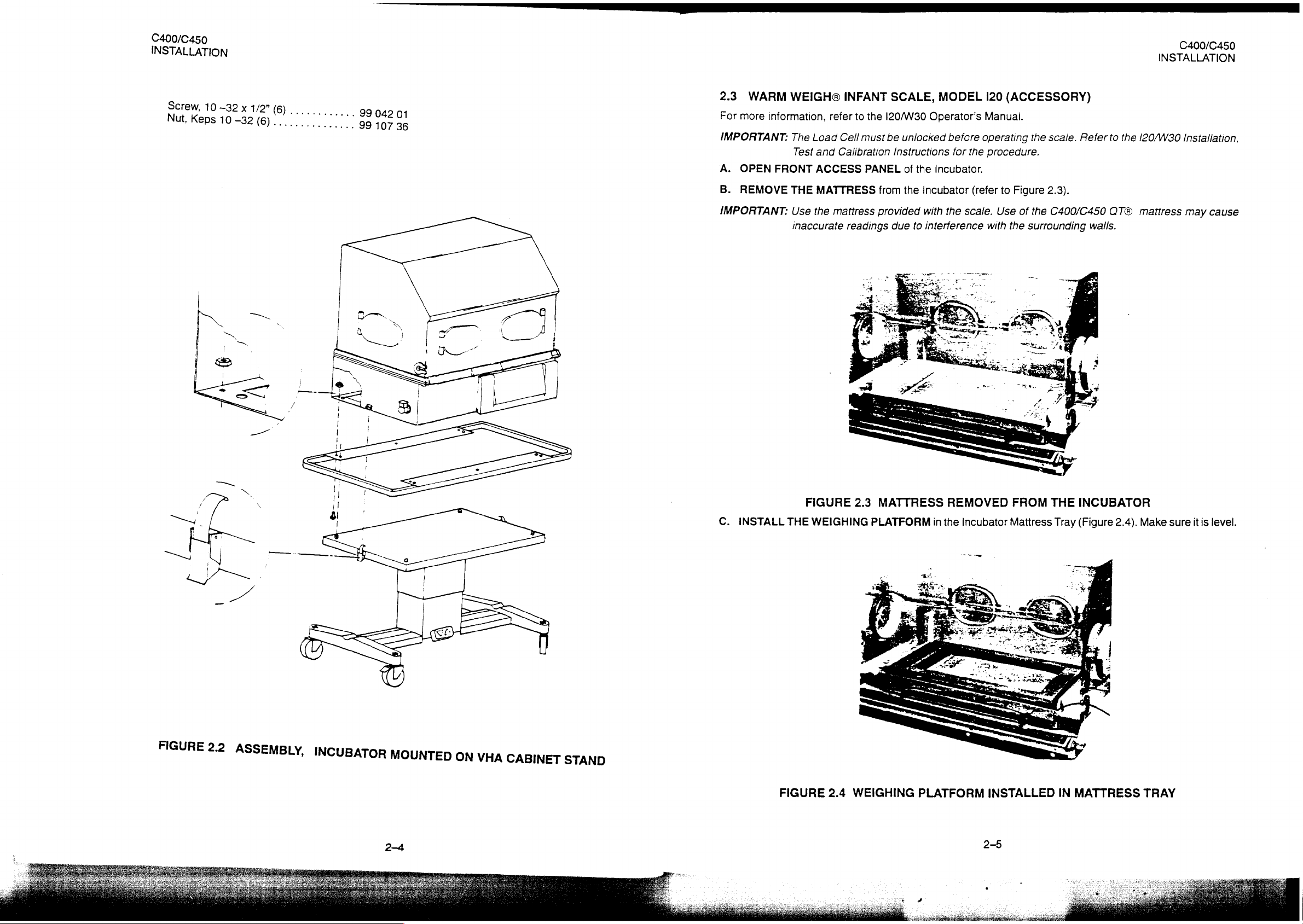
A.
OPEN
B.
REMOVE
IMPORTANT:
WEIGH®
The
Test
FRONT
THE
Use
inaccurate
refer
Load
Cell
and
Calibration
ACCESS
MATTRESS
the
mattress
INFANT
to
the
must
PANEL
from
provided
readings
SCALE,
I20/W30
be
Instructions
due
Operator's
unlocked
of
the
the
Incubator
with the
to
interference
MODEL
Manual.
before
Incubator.
for
the
scale.
operating
(refer
120
(ACCESSORY)
the
procedure.
to
Figure
Use
of
the
with the
surrounding
scale.
Refer
2.3).
C400/C450
walls.
to
the
QT®
400/C450
C
INSTALLATION
120/W30
mattress
Installation,
may
cause
FIGURE
2.2
ASSEMBLY,
INCUBATOR
MOUNTED
ON
VHA
CABINET
STAND
C.
INSTALL
FIGURE
THE
WEIGHING
FIGURE
2.4
2.3
MATTRESS
PLATFORM
WEIGHING
REMOVED
in
the
incubator
PLATFORM
FROM
Mattress
INSTALLED
THE
Tray
IN
INCUBATOR
(Figure
MATTRESS
2.4).
Make
TRAY
sure
it
is
level.
C400/C450
INSTALLATION
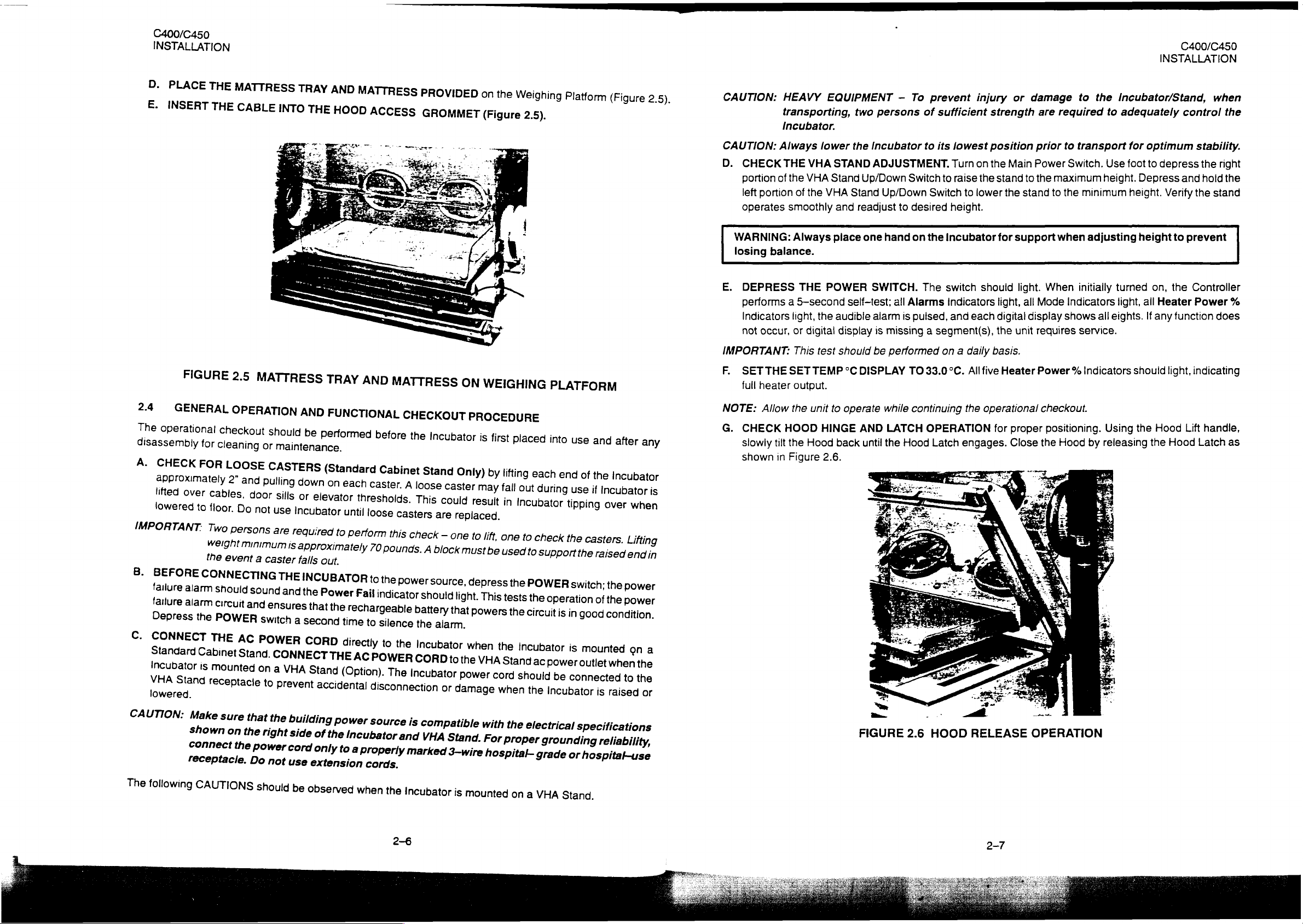
D.
PLAC
E
E.
INSERT
THE
THE
MATTRESS
CABLE
INTO
TRAY
THE
AND
HOOD
MATTRESS
ACCESS
PROVIDED
GROMMET
on
the
(Figure
DS
Weighing
2.5).
Platform
(Figure
2.5).
CAUTION:
HEAVY
EQUIPMENT
transporting,
Incubator.
two
-
persons
To
prevent
of
injury
sufficient
or
damage
strength
are
to
the
required
INSTALLATION
Incubator/Stand,
to
adequately
C400/C450
when
control
the
2.4
The
disassembly
A.
GENERAL
operational
|
CHEC
approximately
lifted
lowered
IMPO
ATANT.
B.
BEFOR
ae
failure
Depress
C.
CONN
Standar
|
ncubator
VHA
omen
Stand
FIGURE
over
to
in
alarm
the
2.5
MATTRESS
OPERATION
checkout
for
cleaning
>
cables,
floor.
: ; i
wor
persons
the
event
m
nala
circuit
POWER
aber
is
mounted
receptacle
or
ard
cannes
door
,
Do
not
minimum
a
La
and
switch
Stana
on
to
should
manto
silis
use
are
required
is
caster
THE
nd
and
ensures
CO
.
a
VHA
р
prevent
TRAY
AND
FUNCTIONAL
b
dee
e
performed
(Standard
Own
on
each
or
elevat
or
Incubator
approximately
falls
INCUBATOR
that
a
second
Stand
until
to
perform
out.
the
Power
the
rechargeable
time
i
directly
(Option).
accidental
i |
AND
thresholds.
Fail
AC
MATTRESS
CHECKOUT
before
caster.
loose
70
to
to
POWER
disconnection
the
i
Cabinet
A
loose
This
casters
this
check
pounds.
the
indicator
.
power
should
battery
silence
to
the
the
Incubator
CORD
The
incubator
Inc
Stand
i
A
source,
i
ubator
Only)
caster
could
are
replaced.
—
one
block
must
light.
at
that
alarm.
to
the
Power
ог
damage
ON
WEIGHING
PROCEDURE
is
is
first
fi
by
may
fall
result
i
to
lift.
one
be
used
depress
This
powers
powers
when
the
VHA
cord
when
placed
lifting
each
out
in
Incubator
to
check
t
the
POWER
tests
th
the
the
circuit
incubator
Stand
ac
should
the
PLATFORM
into
i
use
end
duri
ator
tipping
tippi
the
switch;
circulo
fa
is
uit
is
in
i
is
power
be
connected
Incubator
and
of
the
i
over
reg
casters.
i
i
ond
Socci
mounted
outlet
is
after
any
incubator
we
over
wanes
Lifting
sec
ᾗ
MM
the
power
ower
iti
condition
ona
when
the
to
the
raised
or
CAUTION:
D.
CHECK
portion
left
operates
WARNING:
losing
Always
THE
of
the
portion
smoothly
Always
balance.
of
VHA
VHA
the
lower
STAND
Stand
VHA
and
place
the
Incubator
ADJUSTMENT.
Up/Down
Stand
Up/Down
readjust
one
hand
Switch
to
desired
on
to
its
to
Switch
the
Incubator
lowest
Turn
on
raise
the
to
iower
height.
position
the
Main
stand
to
the
stand
for
support
prior
Power
the
maximum
to
when
to
transport
Switch.
the
minimum
adjusting
for
Use
foot
height.
height.
optimum
to
depress
Depress
Verify
height
stability.
the
and
the
to
prevent
hold
stand
right
the
E.
DEPRESS
performs a 5-second
Indicators
not
occur,
IMPORTANT:
F.
SETTHE
full
heater
NOTE:
G.
Allow
CHECK
slowly
shown
i
light,
or
SET
the
HOOD
tilt
the
in
Figure
THE
the
digital
This
test
TEMP
output.
unit
HINGE
Hood
2.6.
POWER
self-test;
audible
display
should
°C
to
operate
back
SWITCH.
alarm
is
missing a segment(s),
be
performed
DISPLAY
while
AND
LATCH
until
the
The
all
Alarms
is
pulsed,
TO
33.0°C.
continuing
OPERATION
Hood
Latch
switch
should
Indicators
and
each
on a daily
All
five
the
operational
engages.
light.
light,
digital
the
unit
basis.
Heater
for
proper
Close
When
all
Mode
display
requires
initially
Indicators
shows
ail
Service.
Power % Indicators
checkout.
positioning.
the
Hood
Using
by
releasing
turned
light,
eights.
should
the
on,
all
Heater
If
any
Hood
the
the
Controller
Power
function
light,
indicating
Lift
Hood
does
handle,
Latch
as
%
CAUTION:
The
following
ON.
Male
enon
receptacle.
sure
en
CAUTIONS
that
the
power
Do
the
right
not
should
ildi
building
side
of
cord
only
use
extension
be
observed
power
the
Incubator
to
a
source
properly
cords.
when
the
2—6
is
compatible
and
VHA
marked
Incubator
Stand.
3-wire
is
mounted
with
the
electrical
For
proper
hospital-
°
on
grounding
grace
a
VHA
specifications
reliability,
)
or
hospilabuse
Stand.
;
FIGURE
2.6
HOOD
RELEASE
2-7
OPERATION
НЕ
C400/C450
INSTALLATION
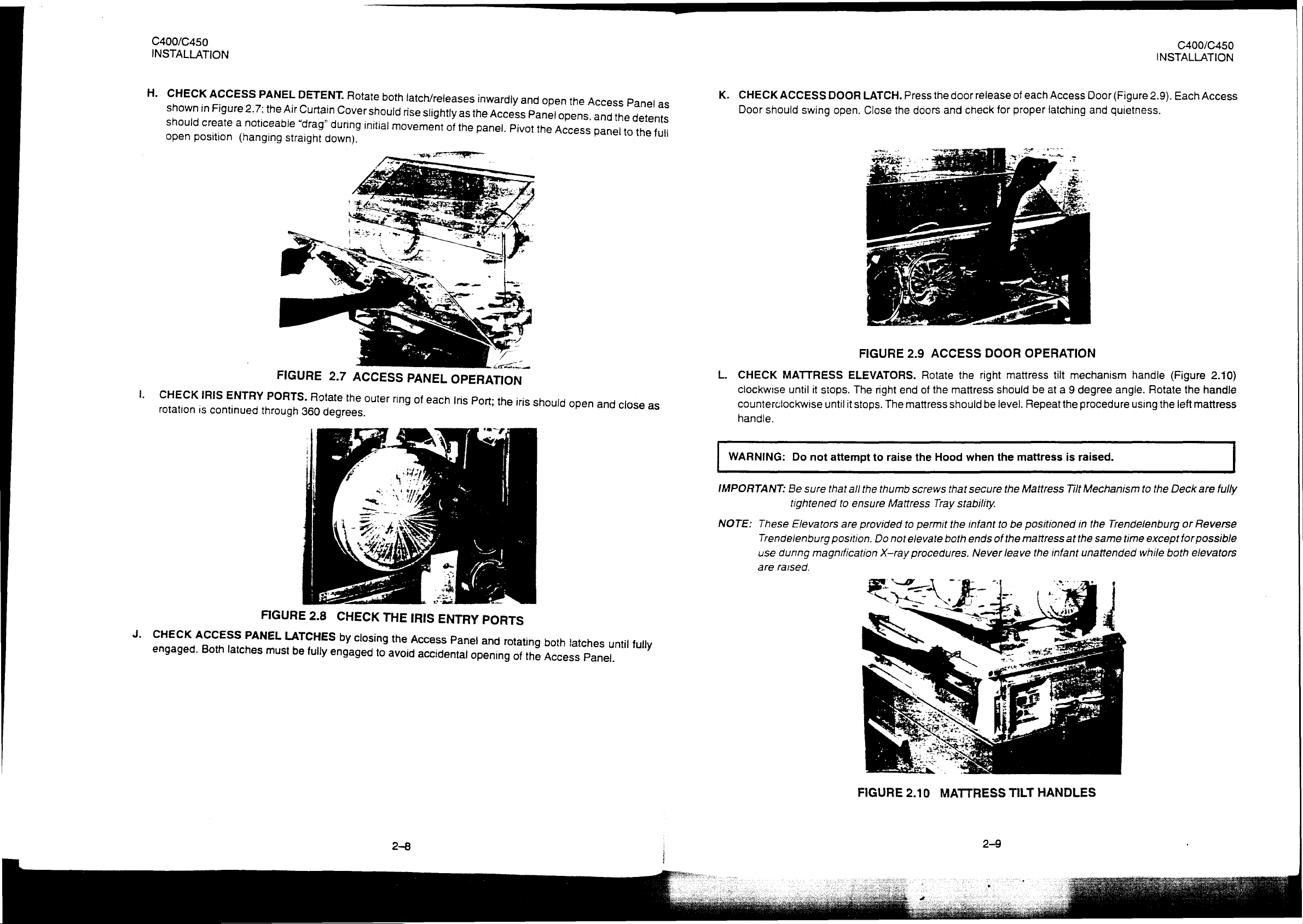
H.
CHECK
shown
should
open
lation
I.
CK
CHECK
ACCESS
in
Figure
create
position
s
continued
IRIS
ENTRY
PANEL
2.7:
the
a
noticeable
(hanging
ov
PORTS.
DETENT.
Air
Curtain
“drag”
straight
Rotate
Cover
during
down).
both
shouid
initial
movement
latch/releases
rise
Slightly
of
as
the
:
nwaraly
the
Access
panel.
and
Panel
Pivot
open
the
the
opens,
Access
Access
and
panel
Panel
the
detents
to
the
full
-
LA
the
a
iri
iris
shoul
uld
open
and
close
as
FIGURE
ooo
.
2.7
ne
Rotate
ACCESS
the
outer
rin
g
PANEL
of
each
OPERATION
i
iris
Port;
as
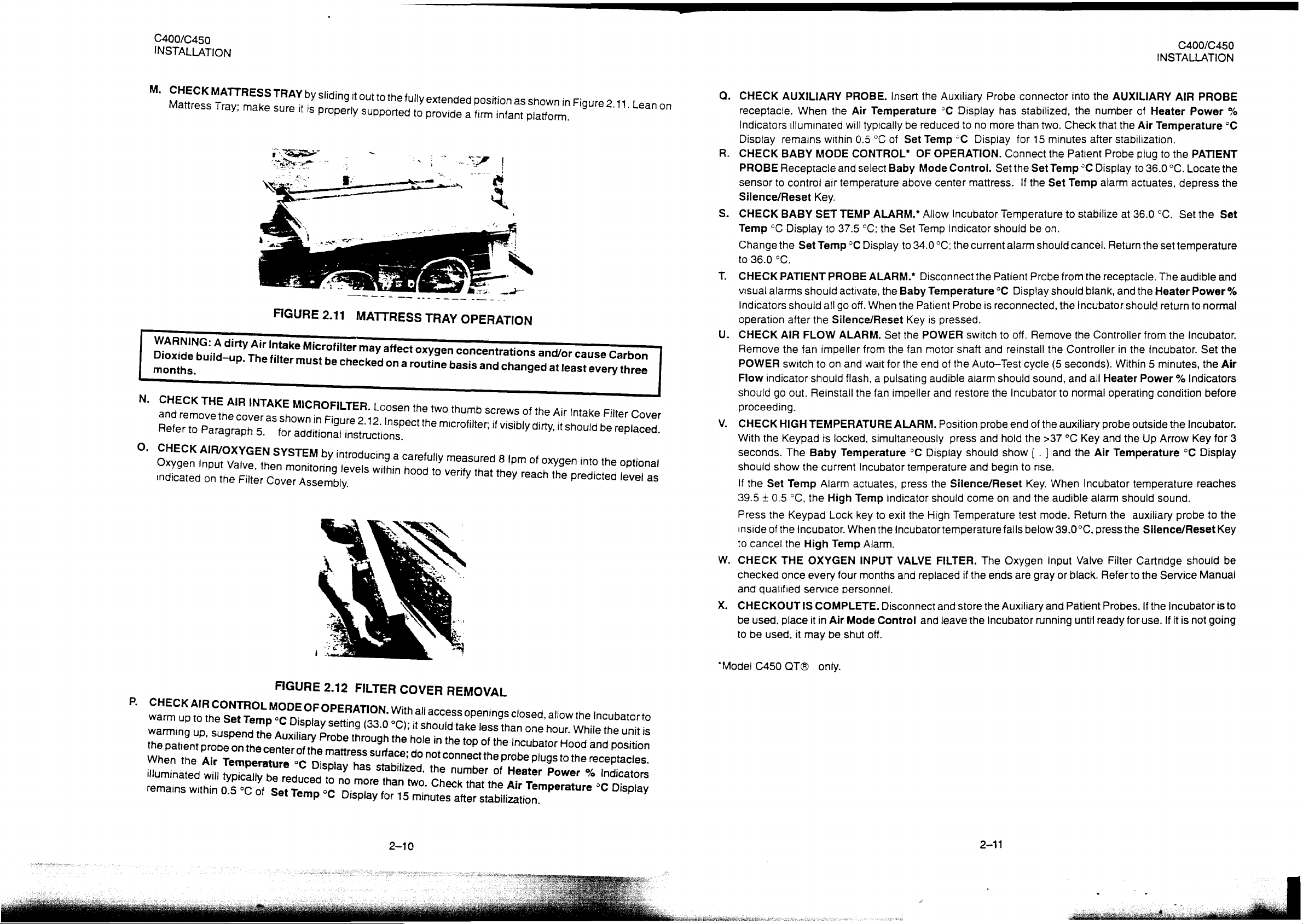
K.
CHECKACCESS
should
Door
L.
CHECK
clockwise
counierciookwise
MATTRESS
swing
until
|
DOOR
it
stops.
untilitstops.
LATCH.
Close
open.
FIGURE
ELEVATORS.
The
ili
the
right
The
Press
the
doors
2.9
ACCESS
Rotate
end
of
the
mattress
door
check
and
the
mattress
should
release
for
DOOR
right
should
be
level.
of
each
proper
OPERATION
mattress
be
Repeat
Access
latching
tilt
mechanism
at a 9
degree
the
procedure
Door
and
(Figure
us
handle
angle.
using
C400/C450
INSTALLATION
2.9).
Each
(Figure
Rotate
|
the
the
left
A
mess
2.10)
handle
mattress
J.
CHECK
engaged.
ACCESS
Both
FIGURE
PANEL
latches
must
WARNING:
IMPORTANT:
NOTE:
These
Trendelenburg
use
during
are
raised.
i
>
2.8
LATCHES
be
fully
ela
CHECK
by
closing
engaged
THE
to
IRIS
the
Access
avoid
し
SEs
ENTRY
Panel
accidental
>
PORTS
and
rotating
opening
of
the
both
latches
Access
until fully
Panel.
Do
not
attempt
Be
sure
that
tightened
Elevators
magnitication
all
the
to
ensure
are
provided
position.
to
raise
thumb
Mattress
Do
not
X-ray
the
Hood
screws
that
Tray
to
permit
elevate
procedures.
the
both
when
the
secure
stability.
infant
ends
of
Never
the
to
the
leave
mattress
Mattress
be
positioned
mattress
the
is
raised.
Tilt
in
at
the
infant
Mechanism
the
Trendelenburg
same
time
unattended
to
the
except
while
Deck
or
for
both
are
fully
Reverse
possible
elevators
2-8
FIGURE
2.10
MATTRESS
2-9
TILT
HANDLES
O
C400/C450
INSTALLATION
M.
CHECKMATTRESS
Mattress
WARNING:
Dioxide
months.
d
Peer
O.
CHECK
Oxygen
indicated
Tray;
A
build-up.
to
Parra
AIR/OXYGEN
Input
on
dirty
graph
Valve,
the
Filter
TRAY
b
y
make
sure
NI
Be
it
i
S
Sliding
properly
it
out
to
supported
the
tully
to
extended
provide
position
a
firm
as
infant
RUE
Air
The
5.
then
FIGURE
Intake
filter
must
as
shown
for
additional
SYSTEM
monitoring
Cover
Za
2.11
Microfilter
be
check
in
Figure
instructions.
by
introducin
levels
Assembly.
MATTRESS
ma
y
affect
ed
on
2.12.
inspect
19
8
within
tl)
τπτ
TRAY
oxygen
a
routine
the
microfilter:
Carefully
hood
to
de
στ
OPERATION
concentrations
basis
and
changed
if
visibly
measured
verify
that
8
they
Ipm
shown
platform.
and/or
at
dirty,
of
oxygen
reach
the
in
Figure
cause
least
every
it
should
into
predicted
2.11.
Carbon
three
be
replaced.
the
optional
level
Leanon
as
Q.
CHECK
receptacle.
Indicators
Display
R.
CHECK
PROBE
sensor
Silence/Reset
$.
CHECK
Temp
Change
to
36.0
T.
CHECK
visual
indicators
operation
U.
CHECK
Remove
POWER
Flow
should
proceeding.
V.
CHECK
With
the
seconds.
should
If
the
39.5 + 0.5
Press
inside
to
cancel
W.
CHECK
checked
and
qualified
X.
CHECKOUT
be
used, place
to
be
AUXILIARY
When
illuminated
remains
BABY
Receptacle
to
control
BABY
°C
Display
the
Set
°C.
PATIENT
alarms
should
should
after
AIR
FLOW
the fan
switch
indicator
go
out.
HIGH
should
Reinstall
TEMPERATURE
Keypad
The
Baby
show
the
Set
Temp
°C,
the
the
Keypad
of
the
Incubator.
the
High
THE
OXYGEN
once
every
service
IS
it
used,
it
may
PROBE.
the Air
within
MODE
air
Temperature
will
typically
0.5
CONTROL*
and
select
temperature
Key.
SET
TEMP
to
37.5
°C;
Temp
°C
Display
PROBE
ALARM.”
activate,
all
go
off.
When
the
Silence/Reset
ALARM.
impeller
to
on
and
from
wait
flash, a pulsating
the
is
locked,
Temperature
current
Alarm
High
Lock
When
Temp
Incubator
actuates,
Temp
key
Alarm.
INPUT
four
months
personnel.
COMPLETE.
in
Air
Mode
be
shut
off.
Insert
the
Auxiliary
°C
be
reduced
°C
of
Set
Temp
OF
OPERATION.
Baby
Mode
Control.
above
ALARM.*
the
Set
to
Allow
Temp
34.0
center
Incubator
Indicator
°C;
the
Disconnect
the
Baby
Temperature
the
Patient
Key
Set
the
the
fan
for
the
fan
impeller
ALARM.
simultaneously
*C
temperature
press
indicator
to
exit
the
the
Incubator temperature
VALVE
and
replaced
Disconnect
Control
Probe
is
pressed.
POWER
motor
end
of
audible
and
Position
press
Display
the
Silence/Reset
should
High
Temperature
FILTER.
and
and
leave
Probe
Display
to
no
°C
Display
mattress.
current
the
is
switch
shaft
and
the
Auto—Test
alarm
restore
probe
and
should
and
come
The
if
the
store
the
the
incubator
connector
has
stabilized,
more
than
two.
for
15
Connect
Set
the
Set
If
the
Temperature
should
Patient
alarm
°C
Display
be
on.
should
Probe
reconnected,
to
off.
Remove
reinstall
cycle
should
the
begin
sound,
Incubator
end
of
hold
the
show
[
to
rise.
the
>37
.
]
Key.
on
and
the
test
mode.
falls
below
Oxygen
ends
are
gray
Auxiliary
and
running
into
the
Check
minutes
the
Patient
Temp
°C
Set
Temp
to
stabilize
cancel.
from
should
the
Incubator
the
the
Controller
(5
seconds).
and
to
normal
auxiliary
°C
Key
and
the
When
audible
Return
39.0°C,
input
Valve
or
black.
Patient
until
the
AUXILIARY
number
that
the
after
stabilization.
Probe
Display
alarm
at
Return
the
receptacle.
blank,
and
should
Controller
in
Within 5 minutes,
all
Heater
operating
probe
and
the
Air
Temperature
incubator
alarm
should
the
press
the
Filter
Refer
Probes.
ready
for
C400/C450
INSTALLATION
AIR
PROBE
of
Heater
Air
Temperature
plug
to
36.0
actuates,
36.0
the
the
Heater
from
the
Incubator.
to
the
°C.
Locate
depress
°C.
Set
set
temperature
The
audible
return
the
Incubator.
Power
PATIENT
the
Set
and
Power
to
normal
Set
the
Power % Indicators
condition
outside
Up
the
Arrow
temperature
before
Incubator.
Key
for
°C
Display
reaches
sound.
auxiliary
Silence/Reset
Cartridge
to
the
if
use.
Service
the
Incubator
if
it
probe
should
Manual
is
not
to
Key
is
going
%
°C
the
the
%
the
Air
3
the
be
to
P.
CHECKA
warm
warming
the
patient
When
|
ate
up
|
up,
the
S
within
っ
he
suspend
probe
An
|
pa
Set
typically
the
on
the
Temperature
center
be
0.5
°C
of
FIGURE
cite
Auxiliary
of
So
reduced
Set
Temp
ay
the
re
Probe
Splay
2.12
κ,
setting
throu
m
attress
to
no
°C
Display
FILTER
(33.0
gh
surface;
has
stabilized,
more
than
for
COVER
With
i
°C);
the
e;
two.
15
2-10
all
access
it
should
hole
i
in
do
not
,
the
Check
minutes
REMOVAL
openings
take
the
top
connect
number
that
after
less
of
the
the
of
the
closed,
than
Incub
probe
Heater
Air
allow
one
h
plugs
prob
ος
Power
Temperature
stabilization.
CH
to
ο
the
Whil
the
the
Incubator
iti
and
postion
iti
receptacies.
σσ
μα,
%
ndic
Indi
°C
Display
to
”
“Model
C450
QT®
only.
2-11
V
O
NÍ
C400/C450
INSTALLATION
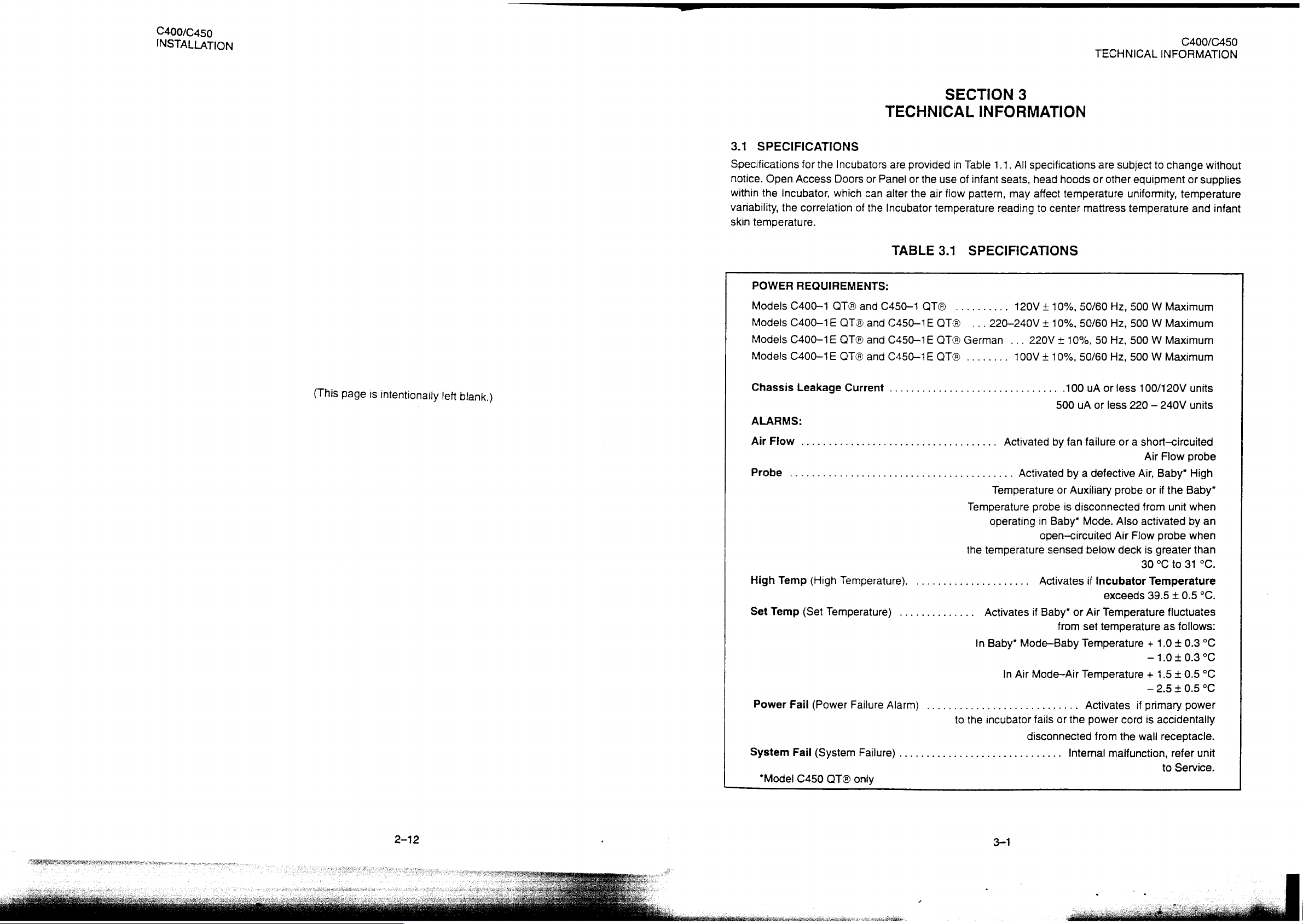
3.1
SPECIFICATIONS
Specifications
notice.
within
variability,
skin
Open
the
incubator,
the
temperature.
POWER
Models
Models
Models
Models
for
the
Incubators
Access
correlation
REQUIREMENTS:
C400-1
C400-1E
C400—1E
C400-1E
Doors
which
QT®
QT®
OTA
QT®
TECHNICAL
are
or
Panel
can
alter
of
the
Incubator
TABLE
and
C450-1
and
C450-1E
and
C450—1E
and
C450-1E
provided
or
the
the
air
temperature
QT®
QT®
QT®
QT®
SECTION
INFORMATION
in
Table
1.1.
use
of
infant
flow
pattern,
reading
3.1
SPECIFICATIONS
..........
...220-240V + 10%,
German
........
3
All
specifications
seats,
head
may
affect
to
120V + 10%,
...
220V + 10%,
100V + 10%,
hoods
temperature
center
mattress
50/60
50/60
50/60
TECHNICAL
are
subject
or
other
eguipment
uniformity,
temperature
Hz,
500 W Maximum
Hz,
500 W Maximum
50
Hz,
500 W Maximum
Hz,
500 W Maximum
C400/C450
INFORMATION
to
change
or
supplies
temperature
and
without
infant
(This
page
is
intentionally
left
blank.)
Chassis
ALARMS:
Air
Probe
High
Set
Power
System
“Model
Leakage
FIOw
....................................
...............................,.........
Temp
(High
Temp
(Set
Fail
Fail
C450
Current
Temperature).
Temperature)
(Power
(System
QT®
Failure
Failure)
only
...............................
Activated
Activated
Temperature
Temperature
operating
the
temperature
.....................
..............
Alarm)
............................
..............................
to
the
Activates
in
Baby*
incubator
probe
if
Mode-Baby
In
Air
Mode-Air
fails or
disconnected
.100
uA
or
500
uA
or
by
fan
failure
by a defective
or
Auxiliary
is
disconnected
in
Baby*
Mode.
open-circuited
sensed
Activates
Baby”
below
if
Incubator
or
Air
Temperature
from
set
temperature
Temperature + 1.0 + 0.8
Temperature + 1.5 + 0.5
Activates
the
power
from
internal
less
100/120V
less
220 — 240V
or a short-circuited
Air
Flow
probe
Air,
Baby*
probe
or
if
the
Baby”
from
unit
when
Also
activated
Air
Flow
deck
is
greater
30 °C
Temperature
exceeds
malfunction,
if
cord
the
wall
39.5 + 0.5
—
—
primary
is
by
probe
when
to
31
fluctuates
as
follows:
1.0
+0.3
2.5
+0.5
power
accidentally
receptacle.
refer
to
Service.
units
units
High
an
than
°C.
°C.
°C
°C
°С
°C
unit
2-12
3-1
C40
TECHNICAL
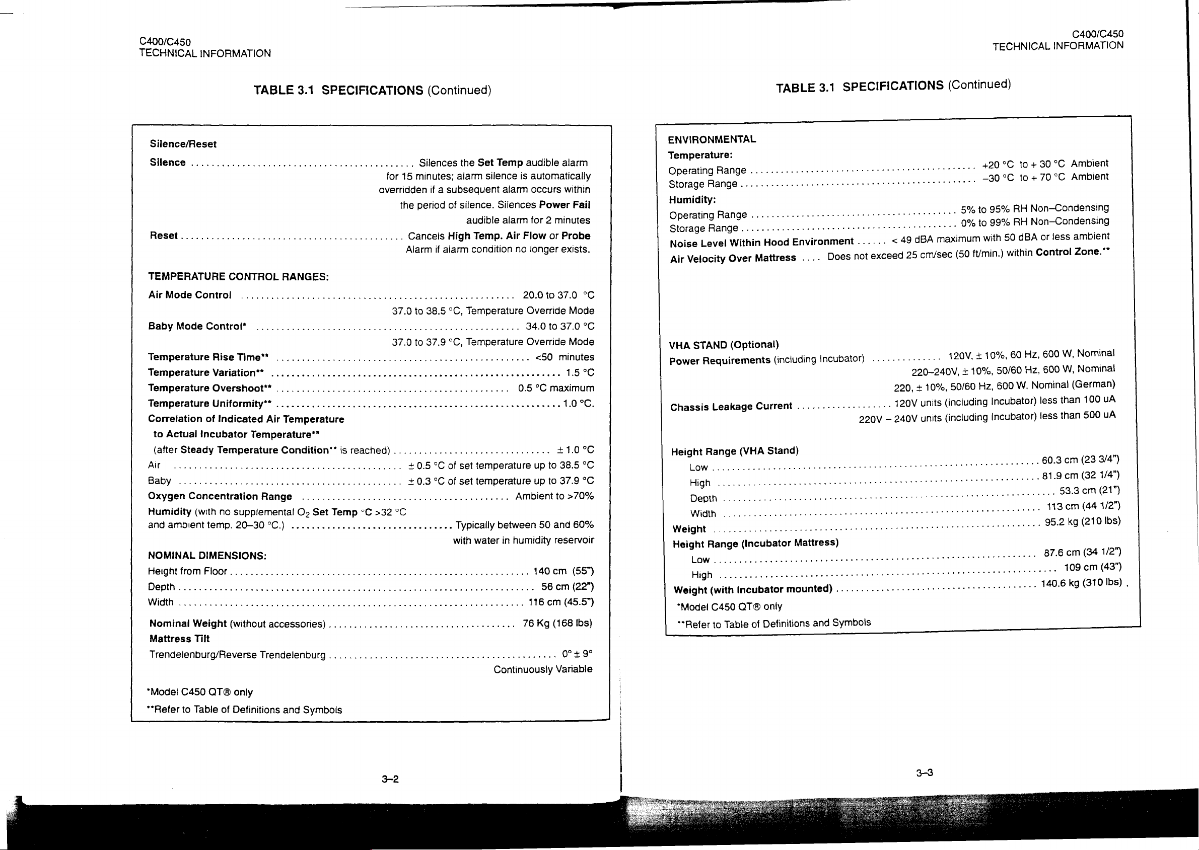
Silence/Reset
Silence
Reset......................................1..
TEMPERATURE
Air
Mode
Baby
Temperature
Temperature
Temperature
Temperature
Correlation
to
Actual
(after
Ar
Baby
Oxygen
Humidity
and
ambient
NOMINAL
Height
Depth
Width
Nominal
Mattress
Trendelenburg/ReverseTrendelenburg.............................
INFORMATION
SPECIFICATIONS
TABLE
............................................
CONTROL
Control
Mode
Control*
of
Incubator
Steady
..................
............................................
Concentration
(with
temp.
DIMENSIONS:
ffrom
Floor
Weight
Tilt
.........................
......,...........................,..,,,....,....2.
Rise
Time"
Variation**
Overshoot**
Uniformity”
Indicated
Temperature
no
supplemental
20-30
(without
Air
Temperature**
Range
°C.)
3.1
RANGES:
.................
......................
.................
.....................
Temperature
Condition”
eee
.........................................
O2
................................
неее
accessories)
is
reached)
Set
Temp
°C
enaz
.....................................
Silences
for
15
minutes;
overridden
the
period
Cancels
Alarm
иене
37.0
to
38.5
37.0
to
37.9
<... < 0000
<..
<<
000000
............................... + 1.0
ον
..
+0.5
0.3
>32
°C
eus
eds
(Continued)
Set
the
alarm
silence
if a subsequent
of
silence.
audible
High
Temp.
if
alarm
condition
няни
нения
°C,
Temperature
°C,
Temperature
a
iie
ee
°C
of
set
temperature
°C
of
set
temperature
Typically
with
water
eee
eue
seen
00.00
audible
Temp
is
automatically
alarm
occurs
Silences
alarm
Air
o n
between
in
Continuously
Power
for 2 minutes
Flow
no
longer
20.0
Override
34.0
Override
<50
K K 0
0.5
°C
up
up
to
Ambient
50
humidity
아이다
140
56
116
76
Kg
or
to
to
maximum
ων
to
ст
alarm
within
Fail
Probe
exists.
37.0
°C
Mode
37.0
°C
Mode
minutes
1.5
°C
1.0
°C.
°C
38.5
°C
37.9
°C
to
>70%
and
60%
reservoir
cm
(55)
ст
(22")
(45.5”)
(168
Ibs)
0° + 9°
Variable
TABLE
ENVIRONMENTAL
Temperature:
Operating
StorageRange.........................
Humidity:
Operating
Storage
Noise
Air
VHA
Power
Chassis
Height
Weight
Weight
"Model
**Refer
Range
Range
Range
Level
Velocity
STAND
Requirements
Leakage
Range
.....................
High
(with
C450
to
..........................:.
..........................:.
..............................
Within
Over
(Optional)
Table
Hood
Mattress
(including
Current
(VHA
Stand)
eee
cece
Incubator
OTA
only
Definitions
of
mounted)
3.1
Environment
....
incubator)
...................
entree
eee
and
SPECIFICATIONS
0...
......
exceed
not
Does
....
220ν
-
eeeeeeeree
ei
eens
...........
Symbols
25
eres
220-240V,
+
220,
120V
240V
(Continued)
cnvsec
120V,
10%,
(including
units
(including
units
5%
0%
ft/min.)
(50
10%,
+
50/60
TECHNICAL
°C
+20
~30°C
95%
to
99%
to
within
10%,
+
50/60
600
Hz,
Incubator)
Incubator)
INFORMATION
+30°C
to
to+70°C
Non-Condensing
RH
Non-Condensing
RH
Control
600
Hz,
60
600
Hz,
Nominal
W,
less
less
60.3
81.9
87.6
C400/C450
Ambient
Ambient
Zone.**
Nominal
W,
Nominal
W,
(German)
100
than
500
than
cm
(23
cm
(32
53.3
cm
cm
(34
109
cm
uA
uA
3/4”)
1/4”)
(21”)
1/2”)
(43)
“Model
**Refer
C450
to
Table
QT®
only
of
Definitions
and
Symbols
C400/C450
TECHNICAL
3.2
THEORY
3.2.1
This
block
3.2.2
The
circulation
is
Supplemental
displaces a portion
of
flowmeter
flow
oxygen
restriction
GENERAL
section
diagram
OVERALL
control
drawn
room
exceeds 8 Ipm, a valve
INFORMATION
OF
contains a functional
of
the
of
temperature,
system
through
air
is
setting,
concentration
is
as
the
oxygen,
controlled
achieved.
OPERATION
Controller
FUNCTIONAL
shown
air
of
room
predictable
intake
which
air
by
the
can
in
within
be
description
is
shown
DESCRIPTION
humidity,
Figures
filter
may
be
to
maintain
impeller/filter
oxygen
the
achieved
in
and
oxygen
3.1
and
by
means
introduced
the
concentrations
oxygen
without
and
detailed
Figure
total
characteristics
3.3.
concentration
3.2. A controlled
of
the
through
gas
inlet
housing
excessive
theory
motor-driven
the
Oxygen
intake
(inciuding
and
within
is
oxygen
of
is
amount
impelier
the
the
Incubator
activated
operation
achieved
of
room
Input
Valve
oxygen)
amount
can
to
restrict
flow.
At
of
by
on
at
of
oxygen
12
the
equipment. A system
means
air
the
on
the
35
be
attained.
air
ipm
of
the
(approximately
Controller.
airintake
lpm.
Since
is
controlled
When
intake
so
maximum
forced
35
filter
cover,
the
amount
by
oxygen
that
higher
air
intake
air
Ipm)
the
desired,
It
probe
receptacle
disconnected,
auxiliary
Inthe
infant’s
the
homeostatic
an
suspended
is
on
probe
Mode
Air
ability
auxiliary
side
the
the
but
becomes
Control
establish
to
control,
may
temperature
air
above
the
of
backup
the
operation,
of
not
probe
mattress
the
Incubator.
sensor
controlling
and
be
within
the
maintain
to
able
can
through
When
the
element
infant’s
own
its
maintain
used
be
weighing
the
plugged
primary
for
temperature
temperature.
a
in,
temperature
air
the
stable
temperature
scale
primary
probe
a
be
Asmail
the
function
infant,
at
control
to
the
temperaiure.
will
一
TECHNICAL
Incubator
and
hole
temperature
air
remains
or
desired
the
air
plugged
connected.
the
of
with
one
C400/C450
INFORMATION
temperature.
a
into
control
temperature
air
underdeveloped
level.
probe
Thus,
This
special
is
the
and
In
addition
a
much
past
reservoir
and
Figures
the
temperature
the
Access
upward
temperature
3.2.3
The
temperature
C400
In
either
desired
Power % Indicators
power
indication
temperature.
to
greater
the
air
flow
for
humidification.
all
the
air
3.1
and
slot
in
the
control
Panel
past
TEMPERATURE
Model
C450
QT®
Incubator
mode
temperature,
required
of
the
drawing
flow
sensor
enters
3.2.
left
end
of
the
opening
in
the
QT®
as
the
of
operation,
to
maintain a given
degree
Each
fresh,
filtered
than
that
of
and
around
When
the
infant
compartment
After
circulating
of
the
main
thermistor
the
Hood
(Figures
Incubator.
CONTROL
Incubator
controlling
provides
the
and
the
relative
on
the
front
of
the
infant s dependency
mode
of
operation
air
into
the
fresh
the
heater
the
Access
within
deck,
and a high
is
open.
the
3.1
and
temperature
parameter;
onty
Air
heater
output
amount
panel.
Changes
temperature.
is
the
incubator,
gas
inflow.
with a predetermined
Panel
up
through
the
infant
past
the
air
temperature
Air
Curtain
3.2)
creating a warm
the
desired
Mode
Control.
is
proportional
of
heat
During
described
the
The
of
the
the
compartment,
temperature
Cover
is
regulated
mode
being
in
the
number
Baby
upon
the
below.
impeller
total
flow
Hood
is
siot
at
the
the
sensing
alarm
thermistor,
is
raised
air
using
is
selected
to
the
provided
of
lamps
Mode
temperature
provides
of
portion
closed,
right
curtain
amount
is
Control,
for
the
fresh
plus
recirculated
being
directed
the
Air
Curtain
end
of
the
air
is
then
recirculated
probe
which
and
back
permitting a portion
which
minimizes
either
Incubator
by a front
of
heat
indicated
illuminated
the
of
its
environment
required
by
the
Modei
internal
main
panel
indicate
recirculation
air
over
the
Cover
deck
as
down
encapsulates
to
the
impeller.
of
the
the
air
or
infant's
key.
to
maintain
number
C450
to
of
the
provides
maintain
is
directed
humidity
is
closed
shown
through
the
When
air
to
drop
The
Model
lit
Heater
amount
at
air
flow
in
air
skin
the
of
an
body
in
AIR
CONTROL
temperature
indicated
located
supplied
temperature
°C
temperature
by
below
to
Display. A second
can
the
deck
the
at
the
to
between
MODE
be
maintained
Set
Temp
and
heater
Set
Temp
sensor
(MODELS
°C
compared
control
39 °C
circuitry
°C
Display
within
and
C400
from
20.0
Display
with
the
setting.
the
40
°C:
QT®
to
37.0
setting.
Set
TempºC
which
air
proportions
Actual
temperature
at
this
temperature,
and
°C
The
C450
QT®).
(20.0
to
Incubator
Display
the
air
temperature
probe
an
in
38.5
°C
air
temperature
setting.
heater
is
serves
alarm
as a backup
is
this
mode
Temperature
is
The
information
output
displayed
to
maintain
by
activated,
of
operation,
Override
monitored
from
Incubator
the
Air
Temperature
to
limit
the
the
heater
the
Mode)
by a probe
this
probe
Incubator
is
shut
off.
air
as
is
air
AIR
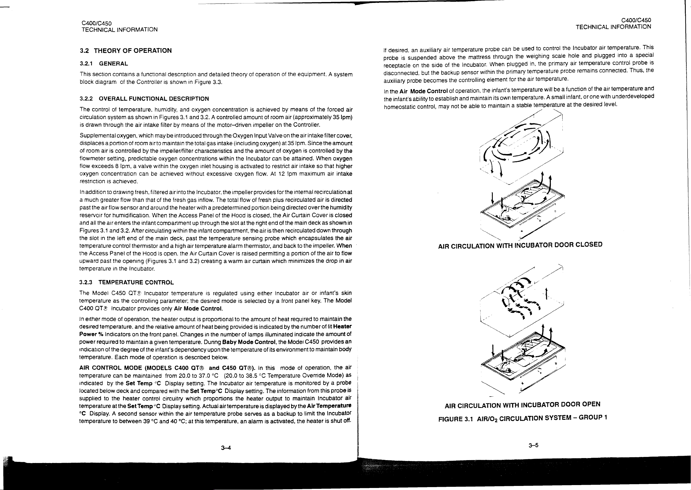
FIGURE
CIRCULATION
AIR/O2
3.1
WITH
INCUBATOR
CIRCULATION
DOOR
SYSTEM
GROUP
—
OPEN
1
C400/C450
TECHNICAL
INFORMATION
AIR
CIRCULATION
WITH
INCUBATOR
DOOR
CLOSED
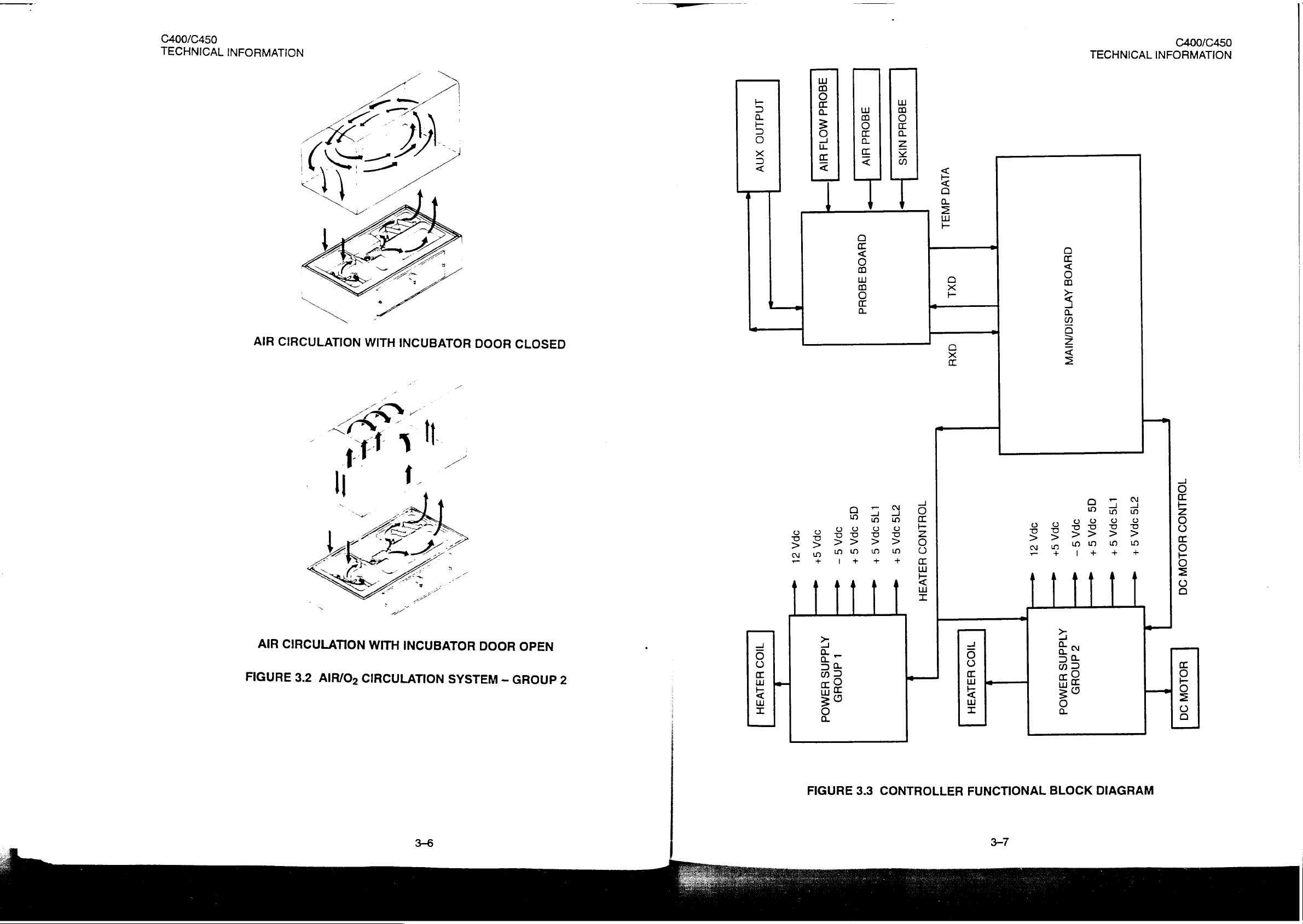
INdINO
Xnv
390Hd
MO
HIV
ag0Hd
HIv
>
01409
390
Hd
C400/C450
ヨ
ヨ
Odd
NIS
TECHNICAL
INFORMATION
VIVO
~
dN3L
OHVOS
9х1
AVIdSIG/NIVW
dXH
AIR
FIGURE
CIRCULATION
3.2
AIR/O;
WITH
CIRCULATION
INCUBATOR
DOOR
SYSTEM
—
GROUP
OPEN
2
1OHLNO9
ZISOPAG+
LISOPAG+
JOHLNOD
OS
PAS
9PPAS—
5
OPA
PAST
ZL
«e
=
1109
431V3H
AlddnS
HAMOd
+
«=
t
dnNOYD
IS
LISOPAG+
DAS
+
a
H31V3H
7109
HJIVAH
OPA
OPA
St
SL
«e
——
GS
5PA
DPA
S+
S-
«----
——
KIdafiS
<
dnOHD
HIMOd
am
«=
HOLON
90
HOLOW
9
=
o
똑
o
:
©
0
る
©
ul
©
-
已
0
©
>
o
2
N
<
2
〇
O
m
=
ン
<
o
=
=
C400/C450
TECHNICAL
INFORMATION
TECHNICAL
C400/C450
INFORMATION
3.2.7.
The
QUIET
C400
QT®
mechanism
simultaneously.
3.2.8
The
SWIVEL
C400
QT®
post-mounted
or
one
of
each.
with
a
metal
3.3
DETAILED
3.3.1
POWER
GENERAL
The
Power
voitage
+12 and
CR1
Regulator
The
display
This
raw
current.
load
HEATER
The
HEATER
optocoupler
U7
is
regulators
—5
and
capacitors
U2
DC
CONTROL
then
applied
Board
VDC
LED
U7.
LATCH
and
of
these
doors
SHELVES,
and
swivel
These
or
see-through
CIRCUIT
SUPPLY
supplies
U1
are
produced
C9
delivers
and
digital
is
then
regulated
is
controlled
This
optocoupler
to
power
ACCESS
C450
QT®
îs
designed
CABINETS
C450
QT®
shelves.
Modules
(acrylic)
DESCRIPTION
all
necessary
through
(+12)
+5V
to
circuitry
down
by
U7
triac
DOORS
Incubators
Standard
The
VHA
may
also
door,
U6.
Transformer
by
center-tapped
and
C10
the
analog
are
to
and
Q2.
(MOC3041)
Q2
which
such
that
AND
Cabinet
Stand
be
equipped
or
voltages
(-5).
Circuitry.
powered
5V
by
U3,
Logic
has
in
turn
are
equipped
the
doors
DRAWERS
Stand
may
be
equipped
with
no
door
at
to
the
T1
has
secondary
Rectified
from
second
U4,
and
level
SSR
a
triac
switches
with
quiet
may
be
(ACCESSORIES)
or
VHA
Stand
with
fold-down
all.
Controller.
a
dual
DC
All
primary
windings
is
then
windings
US.
Three
CTRL
signal
output
with
a
power
to
latching
opened
one
Side
regulated
regulators
may
or
two
Shelves.
DC
voltages
and
two
along
with
rectifier
(J7—7)
with
be
Cabinet
secondary
with
by
are
is
applied
an
zero-crossing
the
heater.
access
elbow
equipped
or
The
Cabinetis
are
generated
full
wave
U1
(+12)
CR2
and
used
in
to
input
detector.
doors.
one
with
The
at
up
Drawer
available
windings.
rectifier
and
capacitor
order
LED
The
output
latch
a
time
to
four
Modules
by
linear
bridge
U6
(-5).
C5.
to
share
of
the
of
or
Allnecessary
VO
ports.
WATCHDOG
The
Watch
connected
generates
decoding
TIMER
Dog
function
to
WDT
audible
KEYPAD
The
Keypad
microcontroller.
pull-up
during
the
SIGNAL
All
temperature
precision
sampled
temperature
is
All
resistors
to
power
CONDITIONERS
(0.1%
tolerance)
by
A/D
units.
ALARMS
High
Temperature
Voltage
eliminate
against
from
all
tolerances
proper
the
the
becomes 0 (Low)
Set
Point
Alarm
Set
point
the
thermistors.
alarms
are
The
functions
AND
is
input
of
signal
during
sampled
keys
except
the
+5D
failure.
signal
conditioner
converter
Alarm
AIR
monitor
in
threshold.
which
is
based
detection
are
RESET
performed
U13.
Should
the
on
the
port
the
supply.
The
circuitry
resistor
U4.
components.
sensed
on
to
The
signal
When
inputs
by
comparison
algorithm
performed
by
the
reset.
PA
by
PAL
U13
(DS1232).
microcontroller
of
the
U11.
SILENCE/RESET
SILENCE/RESET
are
identical.
produce a voltage
software
conditioner
The
both
is
algorithm
is
fed
output
drop
the
between
of
below
microcontroller
the
implemented
block
of
U11.
Microcontroller
stop
Each
key
are
key
is
pulled—up
Each
divider.
is
used
into
amplifier
amplifier
threshold
U9C
(temperature
and
SET
POINT
in
software.
In
addition,
U10
toggling
key
normaily
is
decoded
for
open
thermistor
This
voltage
to
translate
U9C.
(TP2)
is
PAL
U6.
and
actual
U11
toggles
any
momentary
to
VNV
is
connected
is
Its
output
measured
rises),
temperature
has 2 genera!
/O
port
reason,
and
in
order
U13
processed
to
multiplexed
the
divider
is
adjusted
by
comparator
the
comparator
purpose
P1.2
which
resets
by the
switches
remain
in
series
by
U16
voltage
by
RT2
output
measured
is
it
and
with
active
with
and
into
to
U1A
by
in
order
to
maintain
signal
HTR
CUT
LINE
REFERENCE
In
order
to
maintain
from
transformer
then
represents
MOTOR
The
and
conditioned
microcontroller.
3.3.2
CONTROLLER
DC
motor
C.
The
MAIN/DISPLAY
motor
by
MCU
The
microcomputer
(PSD312)
a
safety
(J7-5)
fast
secondary
AC
line
is
controlled
speed
U10B.
A
circuitry
peripheral
standards,
is
applied
system
with
voltage.
(IEC
CONTROLLERS
by
U8,
is
locked
scaled
BOARD
of
the
chip.
mechanical
to
MOSFET
response,
CR4,
filters
with
feedback
in
by
the
value
of
the
Main/Display
AC
line
it
by
signal
motor
relay
K1
transistor
Q1
voltage
C8
and
is
ONLY)
from
the
motor's
SET
—
RPM
current
board
(МОТ-1)
consists
3-10
is
used
which
is
monitored.
applied
hall
from
the
is
of
microcontroller
in
series
with
turns
relay
K1
This
circuitry
to
RT1.
Voltage
effect
sensors
microcontroller
outputted
by
Q2.
Logic
ON
and
OFF.
rectifies
divider
conditioned
into
U9—D
U10A
and
U10
(80C552)
level
control
AC
voltage
output
by
U9A,
and
further
applied
with
(47-3)
B
to
the
U11
|
©
System
Most
Watch
This
microcontroller
Produce
Power
The
switch
and
the-PSD312
assures
Probe
All
back-up
The
Fail
hardware
Dog
function
functions
circuitry
is
fail
an
audible
Fail
microcontoller
remains
produces a POWER
ON.
chip)
proper
Fail
probes
alarm
failures
circuit.
negative
input
of
the
system
(U13)
produces
carned
out
and
remain
and
visual
circuitry
by
High
(via
is
powered
the
Should a power failure
FAIL
alarm
and
are
The
of
AUDIO
condition.
detected
output
U1D
(P4.6
by
voltage
is
biased
the
to a constant
are
monitored
reset
pulses
PAL
chip
(default),
SYSTEM
from
occur
(both
audible
of
the
MCU)
MCU.
In
signal
from
by
the
along
with
U6.
In
addition,
resistor
FAIL
R28
LED)
indication.
nonvolatile
during
the
and
are
pulled
the
case
of
the
U9C
(TP2)
reference
3-11
microcontroller.
audible
beep
should
shall
assert
(VNV)
normal
visual).
to
VNV
AIR
is
fed
which
hardware
power
operation,
Both
control
by
RN2C
monitoring
into
positive
is
equivalent
In
and
SYSTEM
port
source
the
signals
and
probe,
input
to
the
case
of
MCU
FAIL
P3.5
(HDW
fail
condition
as
long
as
MAINS
microcontroller
PWR
RN2B
respectively.
there
is
also a hardware
of
the
comparator
temperature
failure,
LED
FAIL)
into
detects
FAIL
levels
the
flashes.
of
the
PAL
and
power
(PA.0
of
This
U1D.
>50
°C.
it
C400/C450
TECHNICAL
Air
Flow
The
AIR
thermistor,
power
dissipation
be
a
thermal
directly
onto
Since
proportional
the
the
measured
The
C400/450
and
powered
MCU
internal
sounds
A/D
Digitizing
+sign
buffered
The
an
CONVERTER
analog
by
following
AD_RUN
AD_RDY
INFORMATION
FLOW
thermistor
temperature
Circuitry
the
temperature
equilibrium
by
electronic
circuitry
froma
A/D
alarm
and
of
the
temperature
to
digital
U3
(74245).
signals
(MCU
(MCU
is
based
of
into
environment
and
to
the
dissipation
will
change
of
the
circuitry.
senses
12V
source.
converter.
cuts
off
Probe
converter
The
buffering
control
P4.5)
P3.3)
on
the
thermistor
becomes
thermistor’s
this
dissipation
thermistor
voltage
Differential
The
software
the
heater
signals
with
direct
is
A/D
converter:
Start
Conversion
the
self-heating
is
equal
temperature
constant
constant
relates
across
AIR
amplifier
algorithm
when
is
done
binary
necessary
of
the
raised
to
power
of
the
thermistor
to
its
resistance,
FLOW
U9D
then
the
air
by
A/D
outputs.
due
conversion
status
effect
due
to
generated
will
and
thus
thermistor
has
makes
flow
drops
converter
These
to
the
of
the
thermistor.
power
dissipation.
by
be
stable.
packaging.
Steady
any
such
which
a
gain
of
0.307
determination
below
U4
which
outputs
slow
timing
12Rt.
This
Any
state
temperature
changes
is
connected
andits
an
acceptable
is
are
configured
of
the
If
power
It
will
From
steady
forced
can
with
a
dual
A/D
is
applied
continue
this
point
state
temperature
air
which
of
the
be
detected
in
series
output
converter's
regard
level.
slot
integrating
for
an
is
connected
to
8-bit
to
to
rise
until
on
there
is
pushed
thermistor.
and/or
with
R57
air
flow
and
12
bus
and
digital
VO.
the
will
is
to
bit
REMOTE
The
Standard 3 inverters
used
Controller,
by
U2E.
the
exception
condition
AC
C400/450
variations.
equals 4 VDC
is
sensed
heater
DC
DC
dedicated
3.3.3
Remote
to
assure
The
audio
LINE
duty
MOTOR
motor
PROBE
ALARM
Alarm
“half
it
generates
output
control
to
this
is
occur,
RAM
VOLTAGE
heater
AC
REF
at
nominal
by
MCU
cycle.
CONTROL
control
PWM
ports
BOARD
signal
case
control
internal
is
INTERFACE
interface
scheme
supply”
“MUTE”
of
U2E
oscillator
U2A, B and
switching
is
fed
INC
ALM
of
power
consists
signal
into
PAL
is
blocked
failure,
is
active
CORRECTION
algorithm
signal
(J5-3)
line
A/D
represents
and
is
buffered
converter
(GROUP 2 CONTROLLERS
done
by
MCU
by
of
the
80C552
of
audio
oscillator
D.
Since
the
level
required
(J6—-5).
(U6)
when
at
output
employs
DC
by
(P5.4)
controlling
microcontroller.
by
This
signal
which
detects
and
no
audio
BZ1
oscillator
U6—20
feed
equivalent
U9B.
Should
and
software
pulse
forward
and
inverters
scheme.
(-10 V DC)
presence
can
is
and
to
line
algorithm
ONLY)
width
RAM
detector.
used
are
When
the
is
divided
of
be
produced
turned
drives
on by U1
RAM
technique
line
voltage.
voltage
introduces
of
the
output
TECHNICAL
of
the
Schmitt
RAM
by
the
RAM.
by
audio
to
compensate
it
is
adjusted
deviate
U10-5.
The
oscillator
trigger
Module
R17
is
and
When a RAM
transducer
2A.
Should
circuitry
such
from
nominal,
necessary
This
C400/C450
INFORMATION
employs
type,
U12B
connected
R26
and
inverted
is
present,
BZ1.
The
any
other
alarm
ма
J6-1.
control
that
this
for
it
always
grange
corrections
is
one
of
to
the
only
line
the
a
is
to
2
NAD_LEN
NAD
NAD
The
A/D
channel.
POWER
All
power
scaled
by
BATTERY
The
Battery
makes
Q5
a
charges
DISPLAYS
The
C400/450
LED
drivers
outputs.
The
HIGH
HEN
RD
reference
SUPPLY
supplies
resistor
CHARGER
Charger
decision
battery
displays
US,
The
POWER
TEMP
(PSD
PB.5)
(0260)
(PSD
signal
MEASUREMENT
and
battery
dividers
Circuitry
whether
U7
via
limiting
are
and
U8.
to
FAIL
alarm
LED
PC.2)
is
adjusted
in
order
is
charge
LED
These
and
SYSTEM
is
driven
Enable
Enable
Read
by
voltage
resistor
to
built
it
type.
are
are
bring
on
or
not.
R69.
With
serial
by
Low
High
buffer
RT1
in
order
read
by
all
of
them
PNP
transistor
Ifa
charge
the
exception
input/parallel
FAIL
alarms’
U6-15
output
output
output
to
get the
the
internal
into
O5.
is
required,
LEDs
ㆍ
byte
byte
A/D
A/D
The
of
3
indicators,
output
are
driven
most
accurate
converter
converter
MCU
the
MCU
shift
registers
by
reading
of
measurement
monitors
turns
all
of
them
with
MOSFET
for
U10.
These
range.
the
battery
U5—28
are
low
driven
constant
transistors
the
thermistor
voltages
voltage
and
transistor
by
special
current
Q4
and
are
and
sink
Q2.
GENERAL
The
Probe Board
assembly.
first
accepts
connections
External
SERIAL
The
with
provided
galvanic
SKIN
During
switches
(36.00 + 0.08
This
type
of
connector
the
connections
COMMUNICATION
serial
communication
RS232
via
isolation,
PROBE
the
calibration/check,
precision
serves
board
is
will
dual
thermistor
are
maintained
(probes,
compatible
transformer
this
CALIBRATION
resistor
°C)
which
as
an
laid
out
accept
Air
by
RAM
interface
leveis.
T1.
There
port
is
protected
CHECK
the
R4
(4.300
corresponds
interconnection
to
accept
the
Temperature
selecting
It
is
two
single
ended
appropriate 0 Ohms
etc.)
are
option
based
are
(AUXILIARY
on
separate
against
MCU
issues
K)
in
piace
to
the
value
board
types
of
Patient
Probe
protected
the
MAX2S0
input
RFI/EMI
"CAL-PRB”
of
PATIENT
of
R4.
to
PC
mount
Probe
and
against
PORT)
(Rx
D)
by
reduce
connectors
and
the
Air
resistors.
RFI/EMI
provides
and
MAX2S1
and
output
in-line
signal
PROBE
cable
the
Auxiliary
Flow
choke
which
and
harness
for
Sensor.
by
in-line
an
isolated
chip
(Tx
D)
LN3.
turns
the
system
and
simplify
temperature
Air
Probe.
The
proper
chokes
communication
set.
The
isolated
data
passes.
relay
K1
reads
the
contour
probes.
The
of
electric
LN1
and
powers
In
addition
ON.
This
temperature
e
01100
LN2
port
to
[0183
AUDIO
The
audio
and
uses
ALARM
alarm
the
transducer's
is
produced
by
Piezo
Capacitance
transducer
as
a
timing
BZ1.
The
element.
3-12
Oscillator
is
made
up
of
inverters
U17
(4049)
3-13
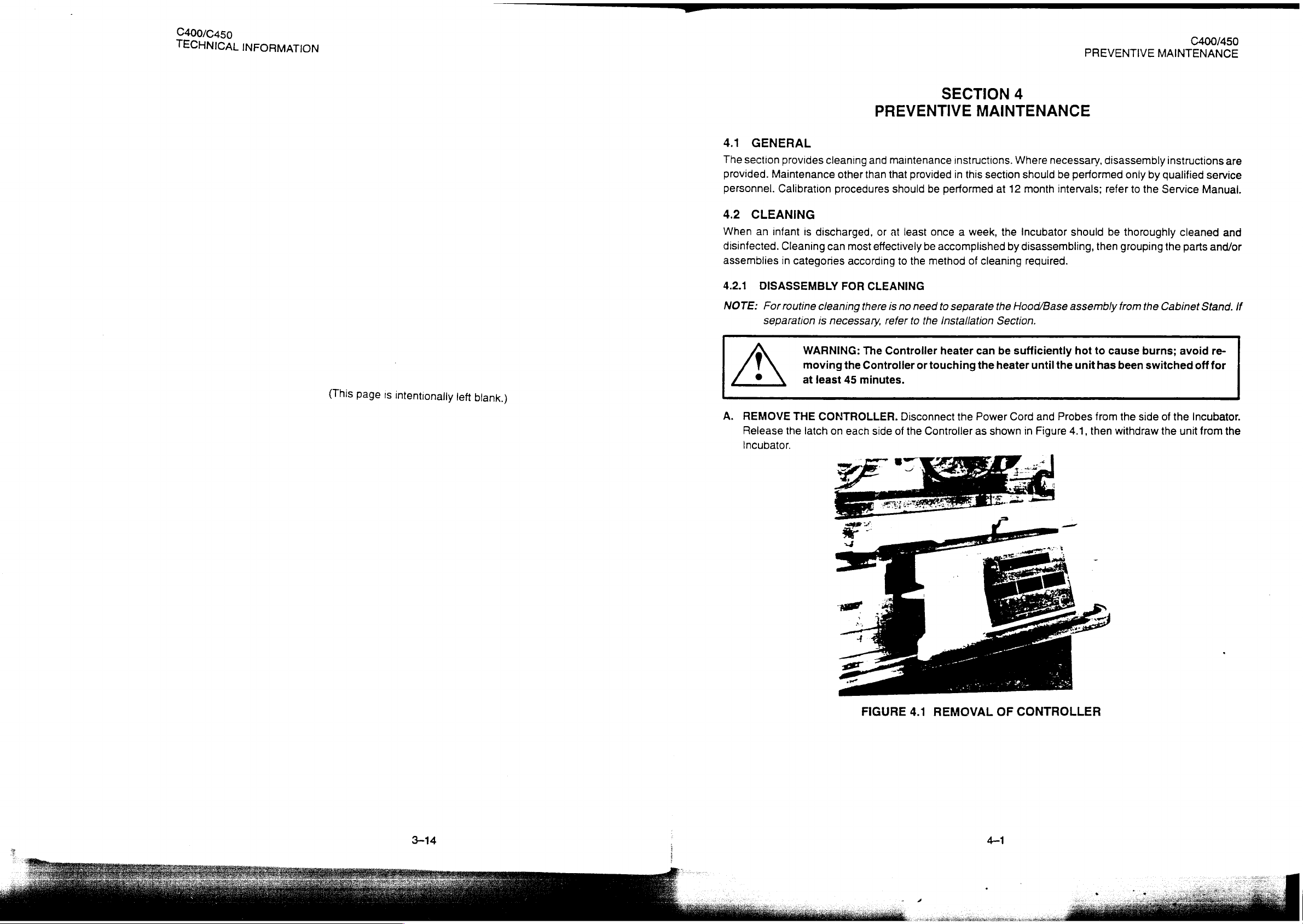
C400/C450
TECHNICAL
INFORMATION
E
PREVENTIVE
MAINTENANCE
<
(This
page
is
intentionally
left
blank.)
4.1
GENERAL
The
section
provided.
personnel.
4.2
When
disinfected.
assemblies
4.2.1.
NOTE:
Maintenance
CLEANING
an
infant
DISASSEMBLY
For
separation
provides
Calibration
Cleaning
in
categories
routine
cleaning
is
discharged,
can
cleaning
is
necessary,
WARNING:
moving
at
least
PREVENTIVE
and
other
than
procedures
or
most
effectively
according
FOR
CLEANING
there
refer
The
Controller
the
Controller
45
minutes.
SECTION
maintenance
that
provided
should
at
is
least
to
the
no
need
to
the
or
be
performed
once a week,
be
accomplished
method
to
Installation
heater
touching
MAINTENANCE
instructions.
in
this
section
at
12
the
by
of
cleaning
separate
the
can
the
Hood/Base
Section.
be
sufficiently
heater
4
Where
necessary,
should
month
Incubator
disassembling,
be
intervals;
required.
assembly
until
the
performed
should
hot
unit
then
to
has
disassembly
only
by
refer
to
the
be
thoroughly
grouping
from
the
Cabinet
cause
been
burns;
switched
instructions
qualified
Service
the
service
Manual.
cleaned
parts
and/or
Stand.
avoid
off
re-
for
are
and
If
A.
REMOVE
Release
Incubator.
THE
the
latch
CONTROLLER.
on
each
side
FIGURE
Disconnect
of
the
Controller
4.1
REMOVAL
the
Power
as
shown
OF
Cord
and
Probes
in
Figure
CONTROLLER
4.1,
from
then
the
side
withdraw
of
the
the
unit
Incubator.
from
the
3-14
|
4-1
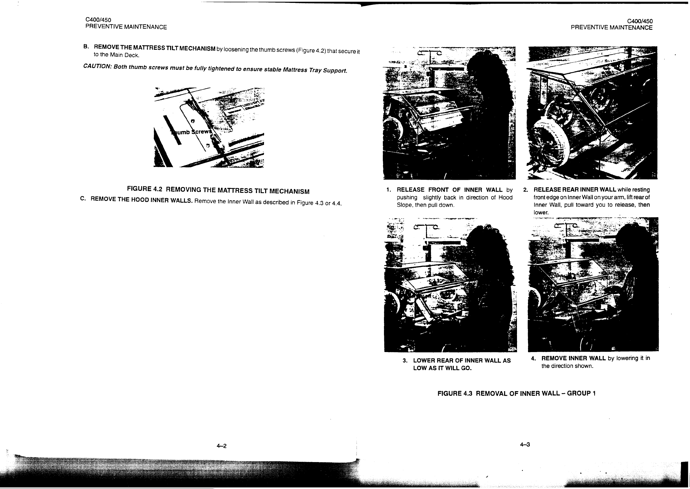
C400/450
PREVENTIVE
B.
REMOVE
to
the
CAUTION:
MAINTENANCE
THE
Man
Dene
Both
MATTRESS
thumb
TILT
screws
MECHANISM
must
be
fully
b
y
loosening
tightened
to
the
g
ensure
thumb
stable
screws
Mattress
(Figure
(Figure
4.2)
Tray
4.
that
Support.
secure
it
|
PREVENTIVE
C400/450
MAINTENANCE
C.
REM
OVE
FIGURE
THE
HOOD
4.2
INNER
REMOVING
WALLS.
THE
Remove
MATTRESS
the
Inner
Wall
TILT
as
described
MECHANISM
.
ーー
in
Figure
4.3
or
4.4.
1.
RELEASE
pushing
Slope,
slightly
then
FRONT
back
pull
down.
AS
REAR
WILL
IT
3.
LOWER
LOW
OF
in
OF
GO.
INNER
direction
INNER
WALL
WALL
of
by
Hood
AS
2.
RELEASE
front
Inner
lower.
ーーーーーー マ ーー
4.
edge
Wall,
geen
REMOVE
direction
the
REAR
on
inner
pull
INNER
INNER
Wail
toward
shown.
on
you
WALL
WALL
your
to
by
while
resting
arm,
lift
release,
lowering
rear
of
then
it
in
FIGURE
4.3
REMOVAL
OF
INNER
WALL — GROUP
1
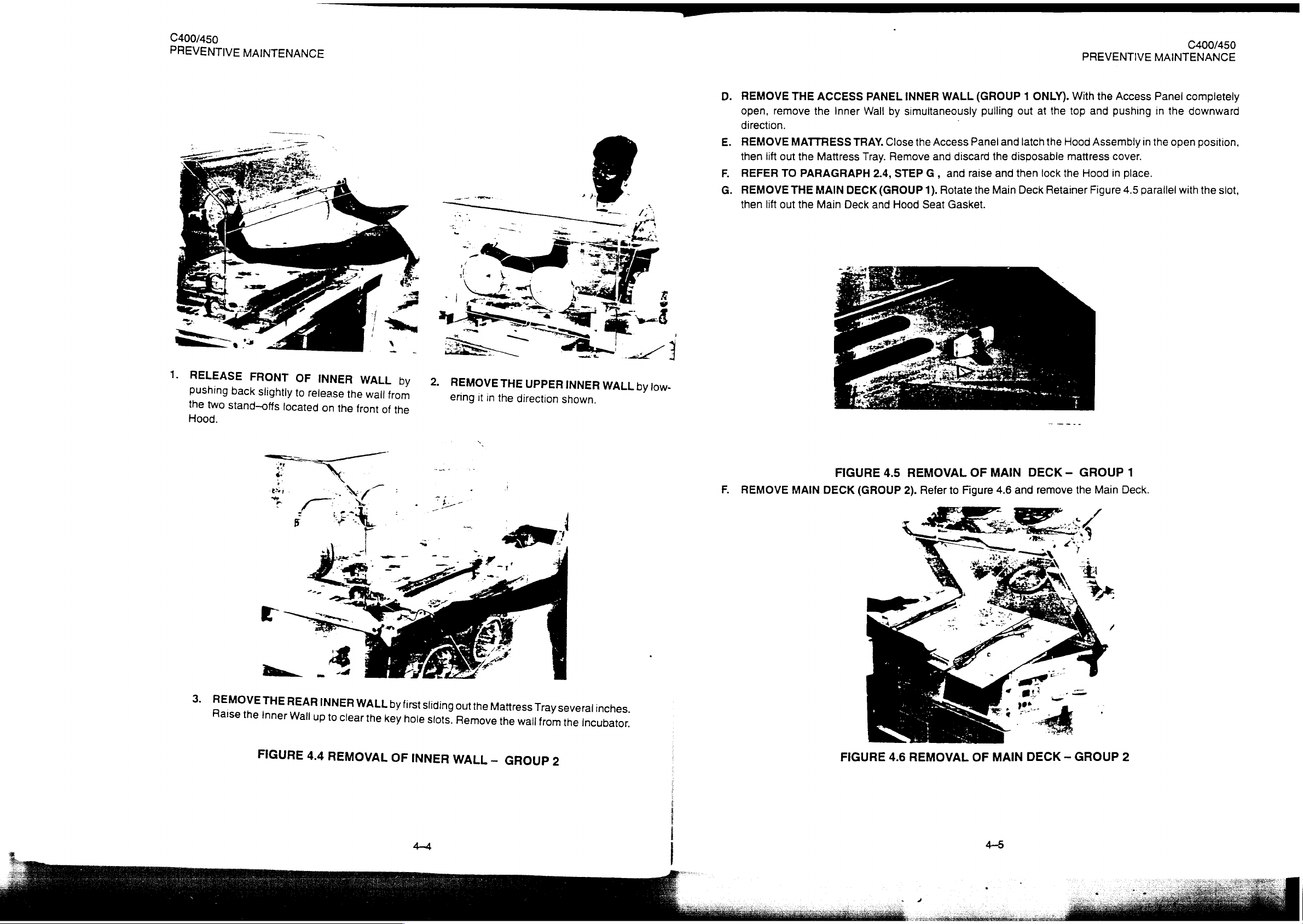
C400/450
PREVENTIVE
MAINTENANCE
PREVENTIVE
C400/450
MAINTENANCE
1.
RELEASE
pushing
the
two
Hood.
FRONT
back
slightly
stand—offs
OF
to
release
located
INNER
on
the
WALL
the
front
wall
from
of
by
the
2.
REMOVE
ering
it
in
THE
the
UPPER
direction
shown.
INNER
WALL
by
low-
REMOVE
open,
direction.
REMOVE
then
lift
REFER
n
REMOVE
then
lift
THE
remove
MATTRESS
out the
TO
THE
out the
ACCESS
the
Inner
Mattress
PARAGRAPH
MAIN
Main
TRAY.
Tray.
DECK
Deck
PANEL
Wall
2.4,
(GROUP
and
INNER
by
simultaneously
Close
the
Remove
STEP
G,
1).
Hood
Seat
WALL
:
Access
and
discard
and
Rotate
Gasket.
(GROUP 1 ONLY).
pulling
Panel
raise
the
out
and
latch
the
disposable
and
then
Main
Deck
at
the
lock
Retainer
With
the top
Hood
mattress
the
the
and
Assembly
Hood
Figure
Access
pushing
in
cover.
in
place.
4.5
parallel
Panei
in
the
the
open
completely
downward
position,
with
the
slot,
3.
REMOVE
aise
THE
the
Inner
FIGURE
REAR
Wail
INNER
up
4.4
WALL
to
clear
the
REMOVAL
by
key
OF
first
sliding
hole
INNER
out
slots.
Remove
WALL
the
Mattress
—
the
wail
GROUP
Tray
from
2
several
the
Incubator.
inches.
F.
REMOVE
MAIN
FIGURE
DECK
FIGURE
4.5
(GROUP
REMOVAL
2).
4.6
Refer
г
+
REMOVAL
to
Figure
OF
OF
MAIN
4.6
MAIN
DECK — GROUP
and
remove
the
DECK — GROUP
Main
1
Deck.
2
 Loading...