

Air-Shields C100, C200 Parts list
で
100/200
PARTS
LIST
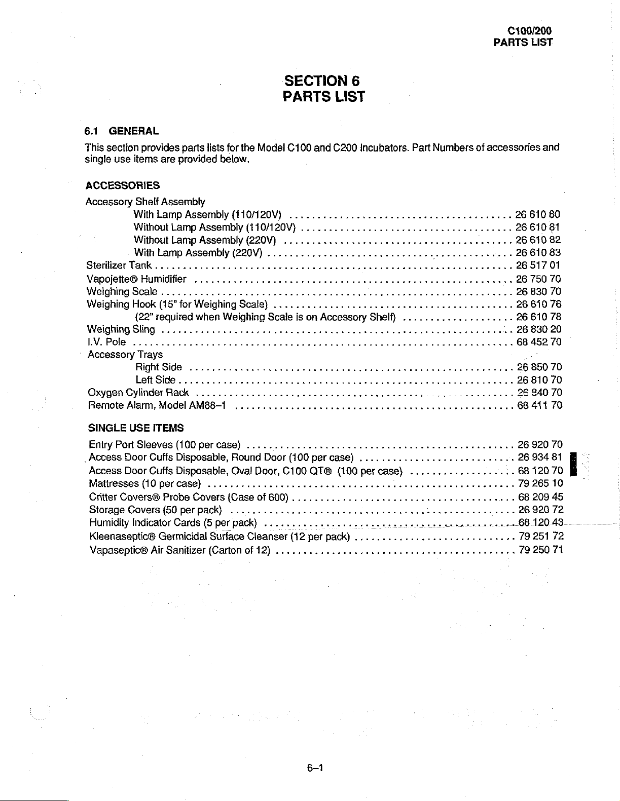
6.1
GENERAL
This
section
single
use
provides
items
are
parts
lists
provided
for
the
below.
Model
ACCESSORIES
Accessory
SterilizerTank.........................
VapojetteB
Weighing
Weighing
WeighingSling
IV.
:
Accessory
PolB
Shelf
Assembly
With
Lamp
Assembly
Without
Without
With
Scale
Hook
(22”
Lamp
Assembly
Lamp
Assembly
Lamp
Assembly
Humidifler
(15"
required
............................
...........................
し
し に に に
for
Weighing
when
ити
Trays
ВОН
$4е
.......
(110/120V)
(220V)
Scale)
Weighing
нуно
(110120V)
(220V)
........,.....................
Scale
leftSide..........................
Oxygen
Remote
Cylinder
Alarm,
Model
Rack
.......,.........,....,..,...,.,,.....2..................
AM68-1
..................................................
SECTION
PARTS
C100
and
6
LIST
C200
Incubators.
Part
Numbers
of
.........,..............................
ων
ερ
ne
tee
ete
..........................
is
on
ни
нии
Accessory
1...
нина
eee
Shelf)
тя
eee
яка
νε ω ων
K
tet
....................
tence
κε
ερ
εω νο
ee
eee
renee
ーー
nen
en
beeen
tenet
K
000
esasan
тяни
eeecreeceuessses
ete
ne
nee
известна
accessories
26
κενο
2661081
eens
etnias
стен
eens
k
26
26
26
26
26
26
26
26
68
tees
26
26
26
68
and
610
80
610
82
610
83
517
01
750
70
830
70
610
76
61078
830
20
452
70
'
850
70
810
70
840
70
411
70
SINGLE
Entry
.
Access
Access
Mattresses
Critter
Storage
Humidity
Kieenaseptic@⑥
Vapaseptic®
USE
Port
Sleeves
Door
Door
(10
Covers®
Covers
Indicator
ITEMS
(100
Cuffs
Disposable,
Cuffs
Disposable,
per
case)
Probe
(50
per
Cards
Germicidal
Air
Sanitizer
per
case)
.................................
Covers
pack)
(5
per
Surface
(Carton
レレ し にし し し に し に に に に に に に に に に に に <
Round
Oval
{Case
............,..........:...,....,.,:,.,,,..,.4..
pack)
Door
(100
per
case)
Door,
C100
QTO
{100
af
600)
.............,...........................
......,..........,... に レー に ーー に ーー…ー
Cleanser
of
12)
(12
per
pack)
....,.........................,.,...,,,.,44
トス に
トト
トト
トト
トト て レト
トレ
て て て ーーーーー・
................,...........
per
case}
................,............
...................
Leen
et
ene
tent
eect
ence
26
920
70
26
934
81
68
120
70
79
265
10
68
209
45
26
920
72
68.120.43
79
251
72
79
250
71
61
100/200
PARTS
LIST
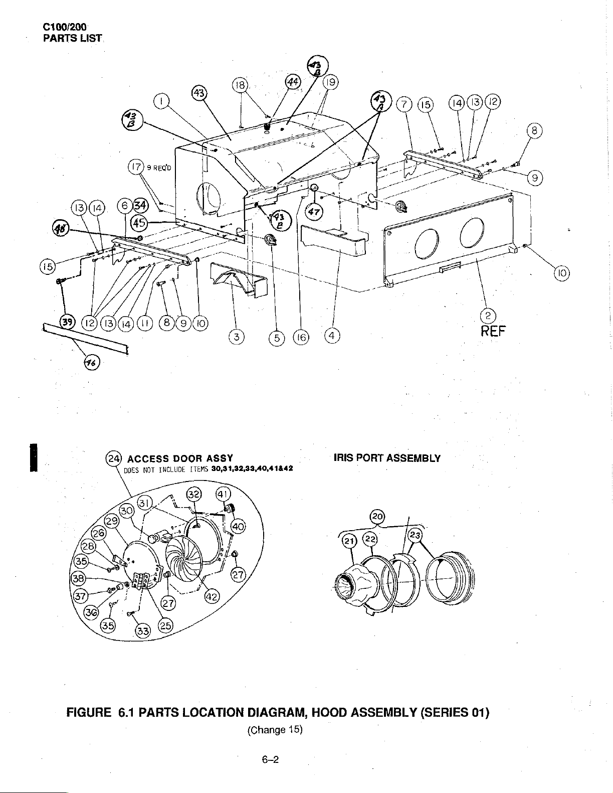
(24)
ACCESS
DOES
NOT
DOOR
INCLUDE
ASSY
30,31,32,33,40,41&42
ITEMS
FIGURE
6.1
PARTS
LOCATION
DIAGRAM,
(Change
15)
IRIS
HOOD
PORT
ASSEMBLY
.
ASSEMBLY
(SERIES
01)
6-2
C100/200
PARTS
LIST
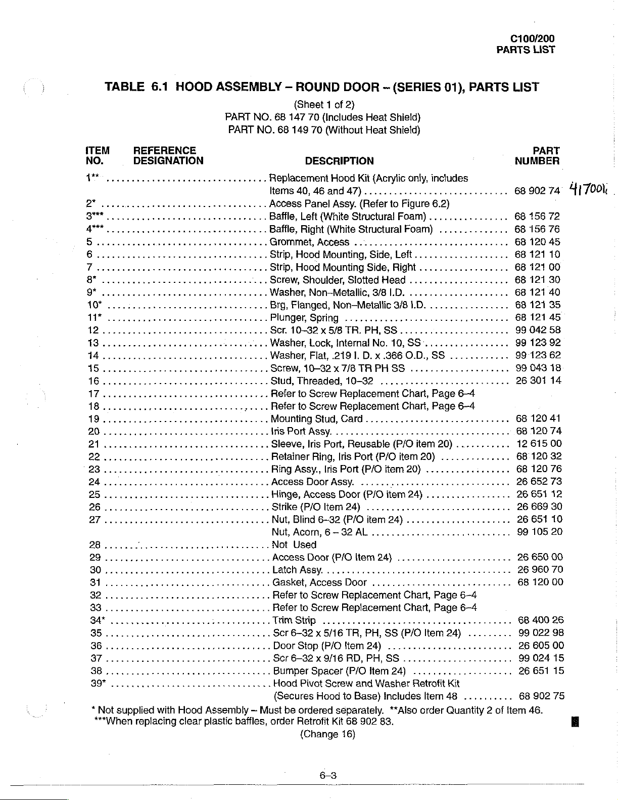
TABLE
ITEM
NO.
V
BY
*
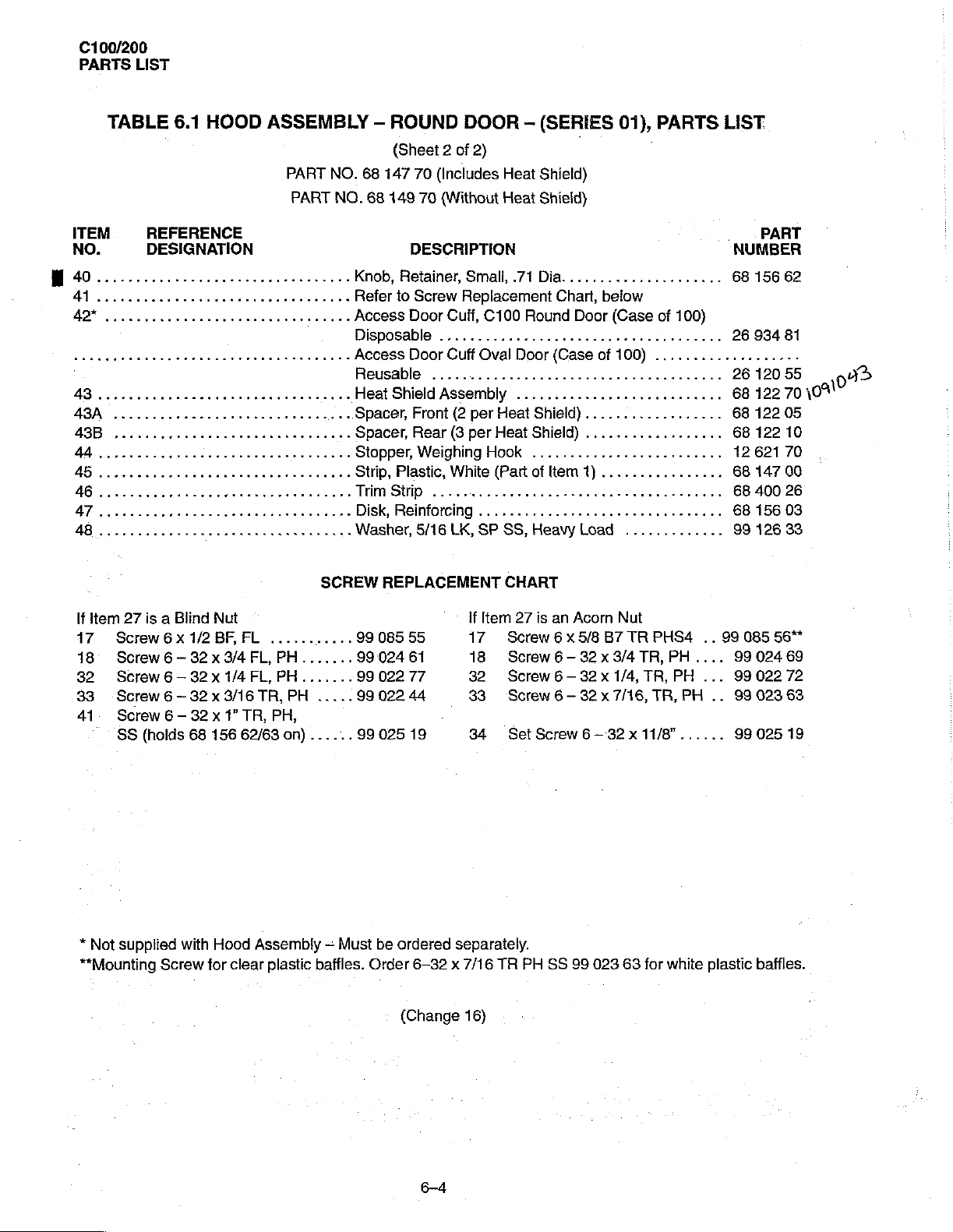
Not
supplied
***When
6.1
HOOD
REFERENCE
DESIGNATION
with
Hood
replacing
clear
ASSEMBLY
PART
NO.
68
PART
NO.
rr
Replacement
Iterns
k
Assembly — Must
plastic
baffles,
Access
Baffle,
Baffle,
Grommet,
Strip,
Strip,
Screw,
...
Washer,
...Brg,Flanged,Non-Metallic
...PlungerSpring
…
Ser.
...
Washer,
...
Washer,
.…
Screw,
Stud,
...
Refer
. .
Refer
Mounting
Iris
Sleeve,
Retainer
Ring
Access
Hinge,
Strike
Nut,Blind6-32(P/Oitem24).....................
Nut,
Not
Access
Latch
Gasket,AccessDoor
Refer
Refer
TimStip
Scr
Door
Scr6—32x9/16RD,PH,SS......................
BumperSpacer(P/Oltem24)
Hood
(Secures
order
—
ROUND
(Sheet 1 of
147
70
68
149
70
DESCRIPTION
40,
46
Panel
Left
Right
HoodMounting,Side,left...................
Hood
Shoulder,
Non-Metallic,
10—32 x 5/8
Lock,
Flat,
10-32 x 7/8
Threaded,
to
Screw
to
Screw
Port
ASSY.
Iris
Ring,
Assy.,
Door
Access
(P/Oltem24)
Acorn, 6 一
Used
Door
Assy.
to
Screw
to
Screw
6-32 x 5/16
Stop
Pivot
be
ordered
Retrofit
(Change
DOOR - (SERIES
2)
(Includes
(Without
Hood
and
Assy.
(White
(White
ACCESS
Mounting
.219
Stud,
2...
Port,
Iris
Assy.
(P/O
...............,.,.....,.,...........
.................
(P/O
Screw
Hood
separately.
Kit
Heat
Shield)
Heat
Shield)
Kit
(Acrylic
47)................,............
(Refer
Structural
Structural
...............................
Side,
Slotted
3/8
.............
TR.
PH,
internal
Replacement
Replacement
Card...
Iris
Port
Door
32AL.
Replacement
Replacement
16)
No.
1,
D.x
TRPHSS
10-82
000000
Reusable
Port
(P/O
(P/O
......
(P/O
........................
Item
24)
............................
TR, PH,
Hem
24)
and
Washer
to
Base)
68
902
only,
to
Figure
Foam)
Foam)
Right
Head
...............
LD.
...............
W81.D.................
SS
......,...............
10,
SS
.3660.D.,
...................,
..............,...........
Chart,
Chart,
(P/O
item
item
20)
P
item
24)
«ων ω εν
.......................
Chart,
Chart,
e
SS
(P/O
............,....,.......
....................
Retrofit
Includes
**Also
83.
01),
includes
6.2)
................
..............
.............
................,
SS
............
Page
6-4
Page
6-4
item
20)
...........
20)
..............
........,........
.................
εν
εντ
ων
Page
6-4
Page
6-4
Item
24)
Kit
Item
48
order
Quantity 2 of
PARTS
..
..
..
0
n
εν ον
.........
..........
item
LIST
PART
NUMBER
68
902
68
156
68
156
68
120
68
121
68
121
68
121
68
121
68
121 35
68
121
99
042
99
123
99
123
99
043
26
301
68
120
68
120
12
615
68
120
68
120
26
652
26
651
26
66930
26
651
99
105
26
650
26
960
68
120
68
400
99
022
26
605
99
024
26
651
68
902
46.
74
417001.
72
76
45
10
00
30
40
45
58
92
62
18
14
41
74
00
32
76
73
12
10
20
00
70
00
26
98
00
15
15
75
6-3
C100/200
PARTS
LIST
TABLE
ITEM
NO.
40.........
4
二
6.1
HOOD
REFERENCE
DESIGNATION
cerco
rr
cer
ASSEMBLY
rrenan
4
ABA
cee
PART
NO.
PART
NO.
mananın
nn n Spacer,
-
ROUND
(Sheet 2 of
68
147
70
68
149
70
DESCRIPTION
Knob,
Retainer,
Refer
to
Screw
Access
Disposable
Access
Reusable
Heat
Spacer,
Stopper,
Strip,
Disk,
Washer,
Door
Door
Shield
Front
Rear
Weighing
Plastic,
Reinforcing
5/16
DOOR
2)
(Includes
(Without
Small,
Replacement
Cuff,
.....................................
Cuff
.........,...................,........
Assembly
(2
per
(3
per
White
LK,
-
(SERIES
01),
PARTS
LIST
|
Heat
Shield)
Heat
Shield)
„PART
NUMBER
.71Dia.....................
Chart,
below
C100
Oval
Round
Door
Door
(Case
(Case
of
100)
of
100)
...................
...........................
Heat
Shield}
Heat
Shield)
Hook
.........................
(Part
of
.....................,,,,.......
SP.SS,
Heavy
..................
....
Кем
1)
................
Load
.............
А
68
156
26
934
26
120
68
122
68
122
68
122
12
621
68
147
68
400
68
99
156
126
62
81
55
70
109)
05
10
70
00
26
03
33
09
う
If
item
27
is a Blind
17
Screw6x1/2BF,FL
18
Screw6-32x3/4
82
Screw6-32x
33
Screw 6 ~
41.
Screw 6 —
"SS
*
Not
**Mounting
(holds
supplied
32 x 3/16
32 x 1”
68
with
Screw
Nut
1/4
156
Hood
for
clear
SCREW
......
ーー
FL,PH.......
FL,PH.......
TR,
PH
.....
TR, PH,
62/63
on)
......
Assembly — Must
plastic
baffles.
REPLACEMENT
99
085
55
99
024
61
99
022
77 32
99
022
44 33
99025
be
ordered
Order
(Change
19
If
Item
17
18
34 Set
separately.
6-32 x 7/16
16)
CHART
27
is
Screw 6x
Screw
Screw 6 -
Screw
Screw
TR
PH SS
an
Acorn
Nut
5/8
B7
TR
PHS4
6-32 x 3/4TR,PH....
32x
1/4,
TR,
PH
6-
32x
7/16,
TR,
PH
6-32 x 11/8”......
99
023
63
for
white
..
99
085
9902469
...
99
..
99
99
plastic
56*
022
72
023
63
025
19
baffles.
100/200
PARTS
LIST
(This
page
is
intentionally
left
blank.)

C100/200
PARTS.LIST
FIGURE
6.2
PARTS
LOCATION
DIAGRAM,
(SERIES
(Change
6-6
ACCESS
01)
13)
PANEL
ASSEMBLY
C100/200
PARTS
LIST
TABLE
ITEM
NO.
MN
2
B
人
SN
[o
PPP
¡A
8
9
©
1
1
1
İM...
TB
16
17
8
aaa
essuie
cece
κε
κω
M
Liveri
K
Libere
P
rr
REFERENCE
DESIGNATION
νο
ον
ii
ei
eee
νε
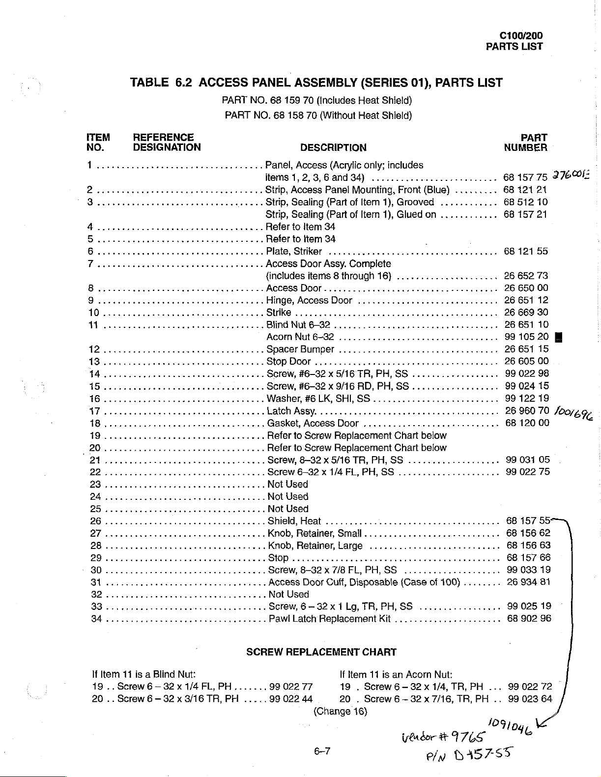
6.2
ACCESS
o
etter
rn
κενν
εννοω ο ον ο κκ ον
sense
PANEL
PART
NO.
PART
NO.
nee
tees
rr
....ShieldHeat...................................
Knob,
ーー
ων
ως
ASSEMBLY
68
159
70
(Includes
68
158
70
(Without
DESCRIPTION
Panel,
items
Strip,
Strip,
Strip,
Access
Access
1,
Access
Sealing
Sealing
Refer
to
Refer
to
Plate,
Striker
(includes
Access
Hinge,
Strike
Blind
AcomNut6—32.......................
Spacer
StopDoor......................................
Screw,
Screw,
Washer,
Latch
Gasket,
Access
..............,.............,,,.....,.,,,
Nut
#6-32 x 5/16
#6-32 x 9/16
Assy.
Refer
to
Refer
to
Screw,
Screw
Not
Not
Not
Knob,
Stop
Screw,
Access
Not
Screw, 6 —
Pawl
8-32 x 5/16
6-32 x 1/4FL,
Used
Used
Used
Retainer,
Retainer,
Used
Latch
(Acıylic
2,
3, 6 and
Panel
(Part
(Part
Item
34
item
34
.....................,..,,......,..
Door
Assy.
items 8 through
Door................................,...
Door
6-32
Bumper
#6
LK,
................
Access
Screw
Screw
8-32 x 7/8
Door
Cuff,
32 x 1
Replacement
(SERIES
Heat
Shield)
Heat
Shield)
only;
includes
34)
..........................
Mounting,
of
Item
of
Item
Complete
,............,.,...............,..
.....................,,........,.
TR,
RD,
SHI,
SS
Door
.............,,.............
Replacement
Replacement
TR,
PH,
Small
............................
Large
FL,
PH,
Disposable
Lg,
TR, PH,
Front
1),
Grooved
1),
Glued
16}
.....................
PH,
SS
PH,
SS
Chart
Chart
PH,
SS
SS
......,,.............
...........................
SS
(Case
SS
Kit
......................
01),
PARTS
(Blue)
............
on
............
LIST
.........
.
1...
0...
...
below
below
...................
sene
of
100)
........
.................
PART
NUMBER
68
157
68
121
68
512
68
157
68
121
26
652
26
650
26
651
26
669
26
651
99
105
26
651
26
605
99
022
99
024
99
122
26960
68
120
99
031
99
022
68
157
68
156
68
156
68
157
99
033
26
934
9902519
68
902
75
27608:
21
10
21
55
73
00
12
30
10
20 圖
15
00
98
15
19
70
beğ;
00
05
75
55
62
63
66
19
81
96
o
If
19
20
Item
..
Screw
..
Screw
11
is a Blind
6-
6—
Nut:
32x
1/4
32 x 3/16
SCREW
FL,PH.......
TR,PH
.....
REPLACEMENT
99
022
77
99
022
44 20 . Screw
If
19 . Screw
(Change
6-7
CHART
Item
16)
17
is
an
6—
6—
Acorn
Nut:
32 x 1/4,
32 x 7/16,
lb
ον
TR,
PH
TR,
PH
7
35795
...
99022
..
99
10910
023
e
72
64
C100/200
PARTS
LIST
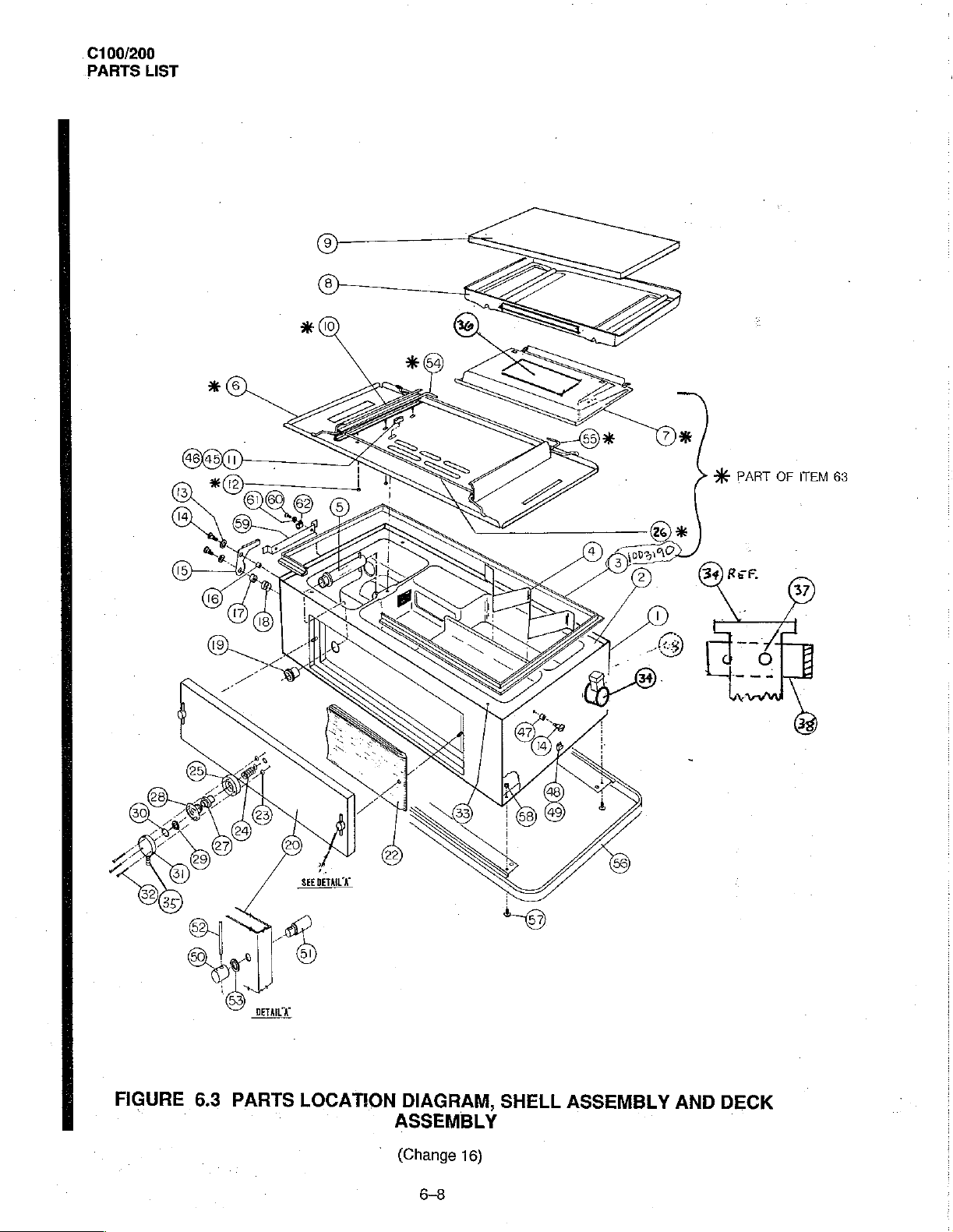
X
PART
OF
ITEM
63
FIGURE
6.3
PARTS
LOCATION
DIAGRAM,
ASSEMBLY
©
(Change
6-8
16)
SHELL
ASSEMBLY
AND
DECK
100/200
PARTS
LIST
ITEM
NO.
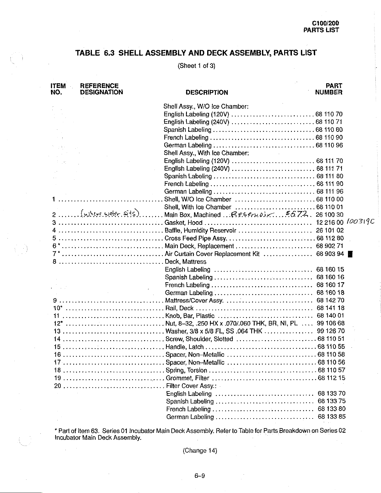
TABLE
REFERENCE
DESIGNATION
6.3
SHELL
站
2.......
9
(here
water,
MW...
E
1
1
_-
SS)
arman
ASSEMBLY
Shell
English
English
Spanish
French
German
Shell
Engiishlabeling(120V)...........................
Englishlabeling(240V)...........................
Spanishtabeling.................................
Frenchlabelingg..................................
German
Shell,
Shell,
Main
Gasket,Hood...................................
Batfle,
Cross
Main
Air
Deck,
EnglishlLabeling
Spanish
French
German
Mattress/Cover
Rail,
Knob,
Nut,
Washer,
Screw,
ME
Spacer,
..
Spacer,
.…
Spring,
.
Grommet,
Filter
English
Spanishlabeling...............................
French
German
AND
(Sheet 1 of
DESCRIPTION
Assy.,
Labeling
Labeling
Labeling
Labeling
Labeling
Assy.,
W/O
With
Box,
Humidity
Feed
Deck,
Curtain
Mattress
Labeling
Deck
Bar,
8-32,
DECK
3)
W/O
.......................,..,.......
With
Labeling
lce
Chamber
Ice
Chamber
Machined
Reservoir
Pipe
Replacement
Cover
Labeling
Laheling
Assy.
.................................
Plastic
.250
HX x .070/.060
3/8 x 5/8
Shoulder,Slotted
Non-Metallic
Non-Metallic
Torsion
...................
Fe
Cover
Assy.:
Labeling
Labeling
Labeling
ASSEMBLY,
ice
Chamber:
(120V)
(240V)
Ice
..................,..,.....
................,..........
......................,......,...
.............................,...
Chamber:
PARTS
LIST
|
©
...............,......,.,....,...
eens
..........................
...
BE
fSf£ru0ix7...£6
.......................,
Assy.
............................
.........................
Replacement
...............................
.......................,........
.............
...........................,....
.....
................,,......,......
FL,
SS
................................
................................
Kit
................
に
THK,
BR,
.064
THK
................
..........................
ω
κενο
NI,
72.
εν
PL
rstrer
εν
.
..
....
..
PART
NUMBER
68
110
70
68
110
71
68
110
80
68
110
90
68
110
96
68
111
70
68
111
71
68
111
80
68
11190
68
111
96
68
110
00
68
110
01
26100
30
1221600
26
101
02
68
112
80
68
902
71
68
903
94
68
160
15
68
160
16
68
160
17
68
160
18
68
142
70
68
141
18
68
140
01
99
106
68
99
126
70
68
11051
68
110
55
6811058
68
110
56
68
110
57
68
112
15
68
133
70
68
133
75
68
133
80
68
133
85
/00319C
E
*
Part
of
item
Incubator
63.
Main
Series
Deck
01
Incubator
Assembly.
Main
Deck
Assembly.
(Change
6-9
Refer
14)
to
Table
for
Parts
Breakdown
on
Series
02
C100/200
PARTS
LIST
TABLE
ITEM
NO.
REFERENCE
DESIGNATION
*
Part
of
tem
Incubator Main
63.
Deck
6.3
SHELL
Series
Assembly.
01
Incubator
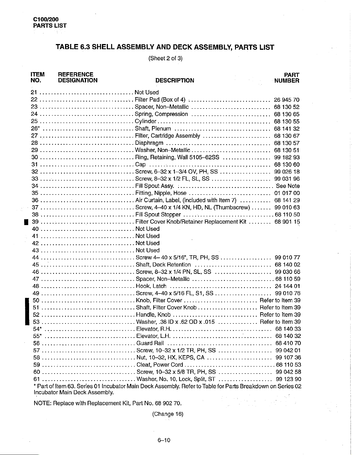
ASSEMBLY
Not
FiterPad(Boxof4).............................
....
Spacer,
....
Spring,
....Cylinder.....................
„..
Shaft,
...
Filter,
..
Diaphragm
Washer,NomMetallc............................
Ring,
CAP
Screw,
Screw,
Fill
Fiting,NippleHose.......................
Air
Screw,
FilSpoutStopper................................
Filter
Not
Not
Not
Not
Screw
Shaft,
Screw,
Spacer,
Hook,
Screw,4-40x5/16FL,S1,SS....................
Knob,
Shaft,
Handle,
Washer,
Elevator
Elevator,
Сиага
Screw,
Nut,
Cleat,PowerCord................................
Screw,10-32x5/8TR,PH,SS...................
Washer,
Main
AND
(Sheet 2 of 3)
DESCRIPTION
Used
Non-Metallic
Compression
Plenum
Cartridge
Retaining,
cr
6-32 x 1-3/4
8-32 x 1/2
Spout
Assy.
Curtain,
4-40 x 1/4
Cover
Used
Used
Used
Used
4-
40 x 5/16”,
Deck
8-32 x 1/4
Non—Metallic
Latch
Filter
Filter
Knob
.38
R.H
LH.
Вай
10-32 x 1/2
10-832,
No,
Deck
Assembly.
DECK
...............
Assembly
Label,
Knob/Retainer
Retention
...........
Cover
Cover
.............................,
IDx
....,..............,.....
.........
HX,
10,
ASSEMBLY,
.........
.........
cece
Wall
5105-62SS
rro
OV, PH,
FL,
SL,
:......................,...
(included
KN,
TR, PH,
PN,SL,
Knob
.620Dx.015
ee
TR, PH,
KEPS,
Lock,
Refer
SS
SS
with
HD,
NL
(Thumbscrew)
Replacement
8S
SS
..,.................
.....................
eee
SS
CA
.......................
Split,
ST
to
Table
for
PARTS
cece
nee
.................
rr
............
Item
7)
..................
..............
eee
eee
...................
...........,.......
Parts
LIST
eet
ene
eens
...
.....
.......
Kit
........
ーー
Breakdown
Refer
Refer
Refer
Refer
k
-=
ek
.
..
..
.
....
...
...
이
on
PART
NUMBER
26
945
68
130
68
190
68
130
68
141
68
130
68
130
68
13051
99
182
68
130
99026
99
031
See
Note
0101700
68
141
9901063
68
110
68
901.15
99
010
68
140
99
030
68
110
24
144
99
010
to
Item 39
to
ltem 39
to
Item
to
Item
68
140
68
140
68
410
99
042
99
107
68
11053
99
042
99
123
Series
70
52
65
55
32
67
57
93
60
18
96
29
50
77
02
66
59
01
76
39
39
33
32
70
01
36
58
90
02
NOTE:
Replace
with
Replacement
Kit,
Part
No.
(Change
68
902
70.
16)
C100/200
PARTS
LIST
TABLE
ITEM
NO.
6
65
66.................................
6
OB
REFERENCE
DESIGNATION
scene
6.3
SHELL
이
이 이 이 이 이 이 이 이 이 이 이 이
renata
5
À
ASSY.
AND
DECK
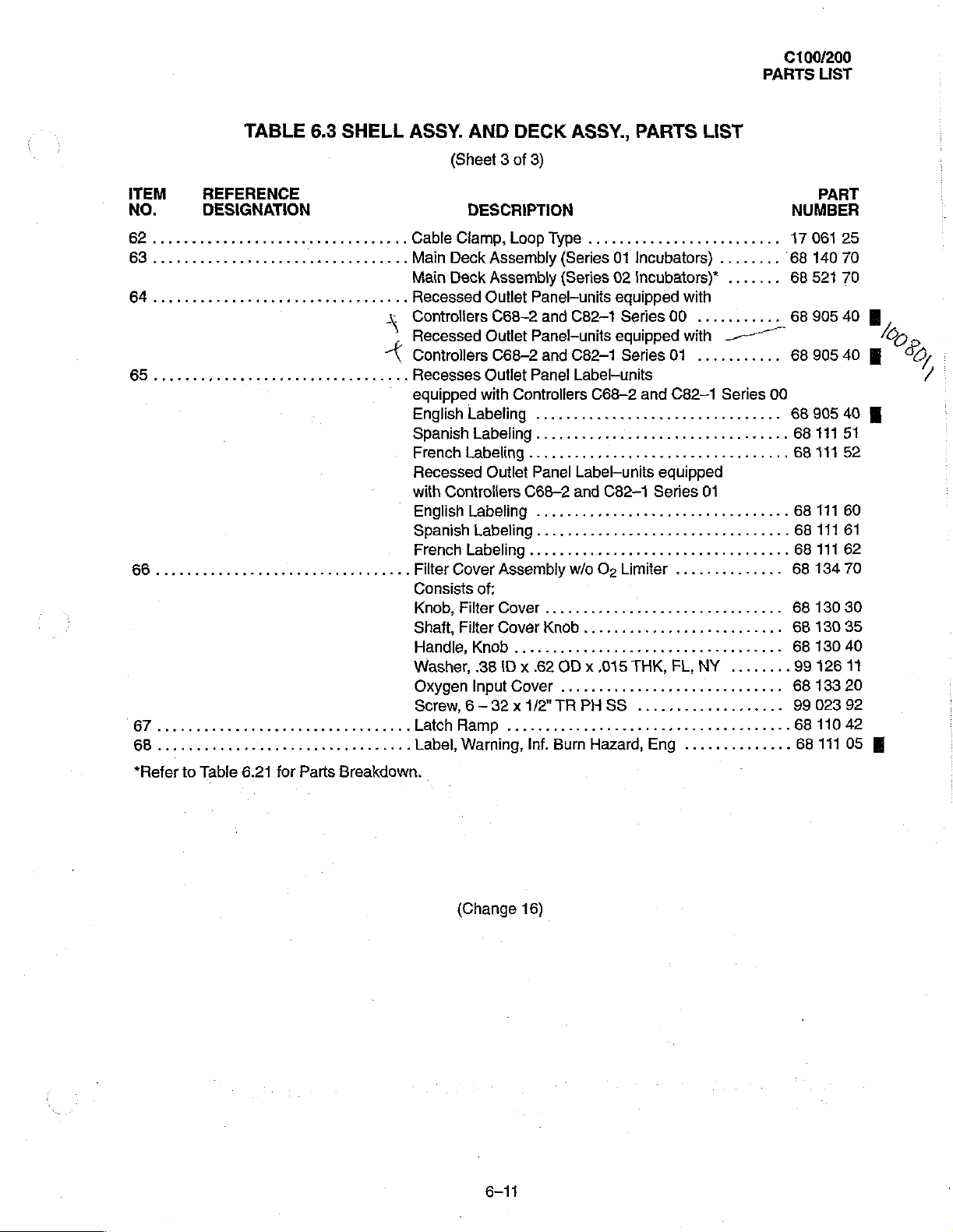
(Sheet 3 of 3)
ASSY.,
PARTS
DESCRIPTION
Cable
Clamp,
Main
Deck
Main
Deck
Recessed
Controiters
Recessed
Controllers
이이
Recesses
equipped
English
Spanish
French
Recessed
with
Controliers
English
Spanish
French
Filter
Cover
Consists
Knob,FilterCover...............................
Shaft,FilterCoverKnob.....................
Handle,
Washer,
Oxygen
Screw,
latchRamp
Label,
Warning,
Loop
Type
........................,
Assembly
Assembly
Outlet
C68—2
Outlet
C68-2
Outlet
with
Controllers
Labeling
Labeling
Labeling
Outlet
Labeling
Labeling
Labeling
Assembly
of:
Knob
.38
ID x .62
Input
Cover
6-32 x 1/2"
...............................
(Series
(Series
Panel-units
and
Panel-units
and
Panel
................................
......................,......,,..
.........,........,......,........
Panel
C68—2
........,........,....,...,......
........................,........
......................,.....,.....
..................,.,..,......
OD x .015
........................
TRPHSS
Inf.
Bum
01
Incubators) ........
02
Incubators)*
eguipped
C82-1
C82-1
Label-units
and
w/o
Series
eguipped
Series
C68-2
Label-units
Hazard,
C82—1
Oz
Limiter
THK,
and
............
equipped
Series
Eng
with
00
...........
with
Li
01
C82-1
..............
FL,
NY
..............
LIST
.......
-一
Series
01
..
‘68
一
00
..
.
...
...
..
....
PART
NUMBER
17
061
25
140
70
68
521 70
68
905
40 圖
6890540
68
90540
68
111
51
68
111
52
68
111
60
68
111
61
68
111
62
68
134
70
68
130
30
6813035
68
130
40
99
126
11
68
133
20
99
023
92
68
110
42
68
111
05
М
圖
の
。
İZ,
/
*Refer
to
Table
6.21
for
Parts
Breakdown.
(Change
6-11
16)
C100/200
PARTS
LIST
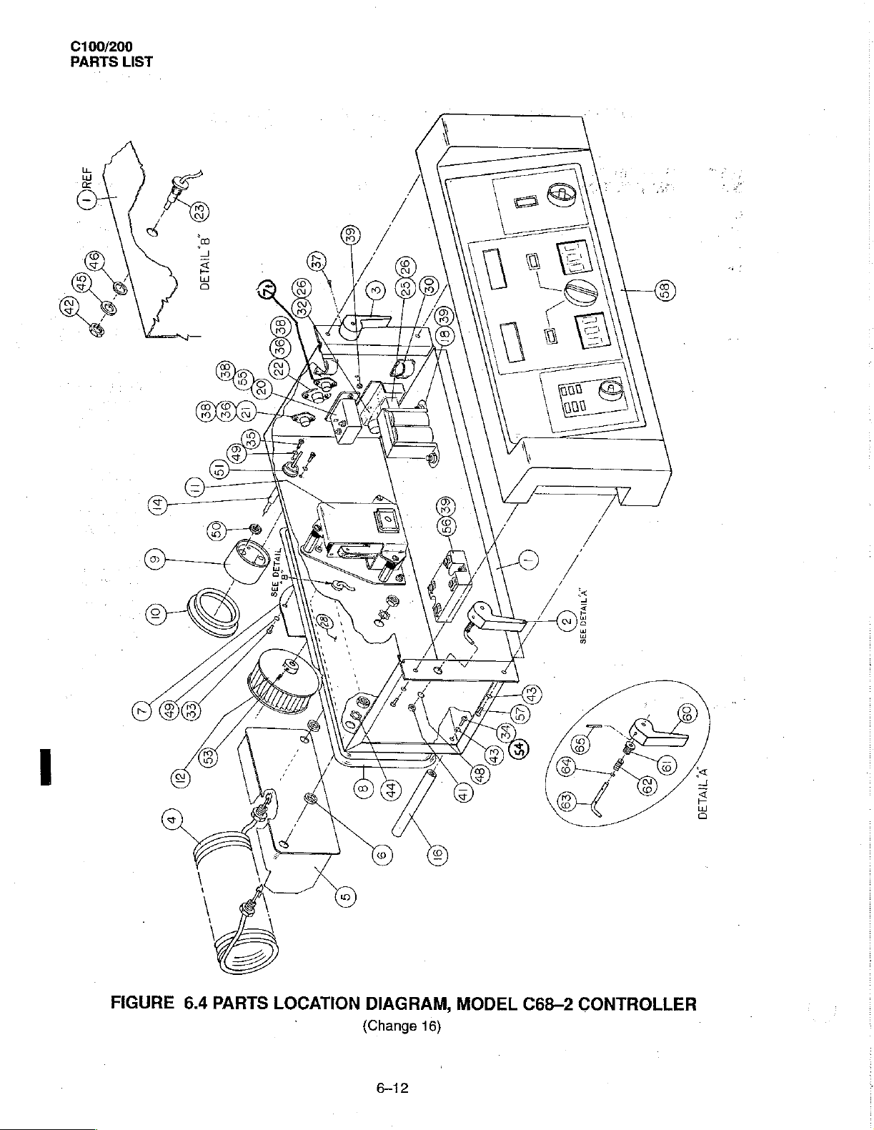
FIGURE
6.4
PARTS
LOCATION
DIAGRAM,
(Change
6-12
16)
MODEL
C68-2
IL
ヨロ
CONTROLLER
C100/200
PARTS
LIST
ITEM
NO.
人
2
Qro
4.......
5
TABLE
PART
NO.
PART
NO.
PART
NO.
PART
NO.
REFERENCE
DESIGNATION
rr
HTR1
HHTRT
HTR1
....................
..........,.,,,.....
re
nere
68
68
68
68
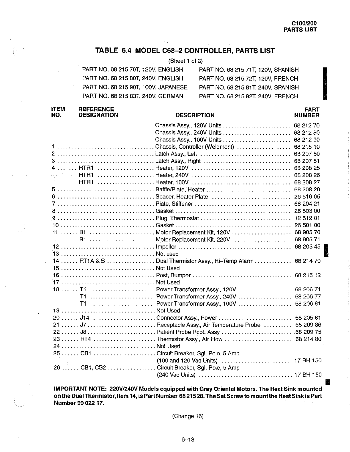
6.4
215
215
215
215
rr
MODEL
70T,
80T,
90T,
83T,
ee
120V,
240V,
100V,
240V,
eee
eee
ων
6.........................,....,...
7
C68-2
ENGLISH
ENGLISH
JAPANESE
GERMAN
CONTROLLER,
{Sheet 1 of
3)
PART
PART
PART
PART
NO.
NO.
NO.
NO.
68
68
68
68
PARTS
215
71T,
215
72T,
215
81T,
215
82T,
LIST
120V,
120V,
240V,
240V,
SPANISH
FRENCH
SPANISH
FRENCH
DESCRIPTION
Chassis
Chassis
Chassis
Chassis,
Latch
Latch
Heater,
Heater,
Heater,
Assy.,
Assy.,
Assy.,
Controller
Assy.,
Assy.,
120V
240V
100V
120V
Units
........................
240V
Units
.....
100V
Units
.....
(Weldment)
Left
............................
Right
...:..............,....,.......
BafftePlate,Heater..............................
Spacer,
Plate,
Motor
„.
Motor
Impeller
Not
Dual
Not
Post,
Not
Power
Power
Power
Not
ConnectorAssy.,Power..........................
Receptacle
Patient
Thermistor
Not
Circuit
(100
Circuit
(240
Heater
Stiffener
Replacement
Replacement
Plate
Kit,
Kit,
eee
120V
220V
2.
used
Thermistor
Assy.,
Hi-Temp
Alarm
.............
Used
Bumper
.........:..........,.....,,...,,,.
Used
Transformer
TransformerAssy.,240V...................
Transformer
Assy.,
120V...................
Assy.,100V...................
Used
Assy.,
Air
Probe
Assy.,
Rcpt.
Air
Temperature
Assy
...........:.............
Flow
........................
Probe
Used
Breaker,
and
Breaker,
Vac
120
Vac
Units)
Sgl.
Pole, 5 Amp
Units)
Sgl.
........................,
Pole, 5 Amp
.................................
eee
cee
..........
..
..
...
.
ke
PART
NUMBER
68
212
68
212
68
212
68
215
68
207
68
207
68
208
68
208
68
208
68
208
26
516
68
204
26
503
1251201
26
501
68
905
68
905
68
205
68
214
68
215
68
206
68
206
68
206
68
205
68
209
.68
209
68
214
17
BH
17
BH
70
80
90
10
80
81
25
26
27
20
05
21
00
00
70
71
45
70
12
71
77
81
81
86
75
80
150
150
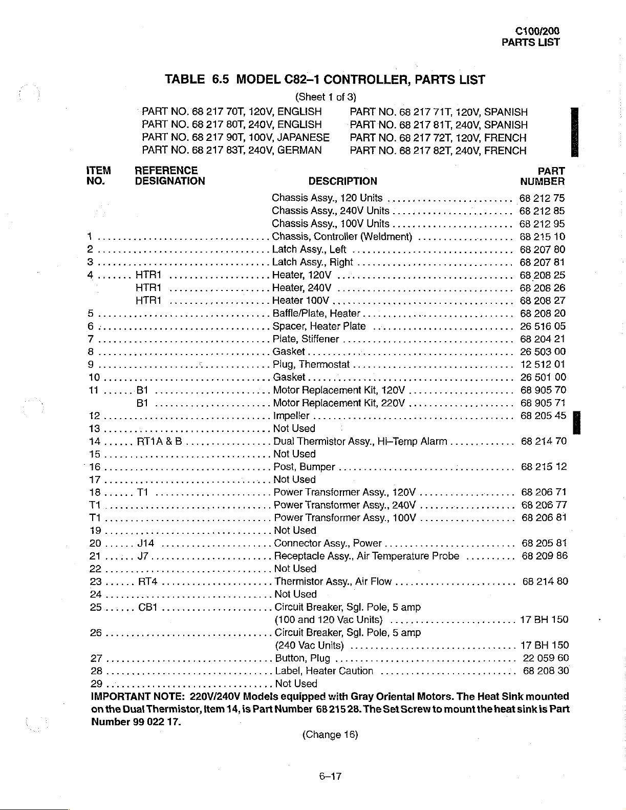
IMPORTANT
on
the
Dual
Number
99
NOTE:
Thermistor,
022
220V/240V
17.
ltem
14,
Models
is
Part
equipped
Number
(Change
68
6-13
with
215
16)
Gray
28.
Oriental
The
Set
Motors.
Screw
to
The
mount
Heat
the
Heat Sink
Sink
mounted
is
Part
C100/200
PARTS
LIST
TABLE
PART
NO.
PART
NO.
PART
NO.
PART
NO.
ITEM
NO.
2
28...
0
REFERENCE
DESIGNAFION
AB
59
“Used
only
with
item
68
68
68
68
ncia
13.
6.4
215
215
215
215
re
errar
MODEL
70T,
80T,
240V,
90T,
83T,
cera
ses...
C68-2
120V,
ENGLISH
ENGLISH
100V,
JAPANESE
240V,
GERMAN
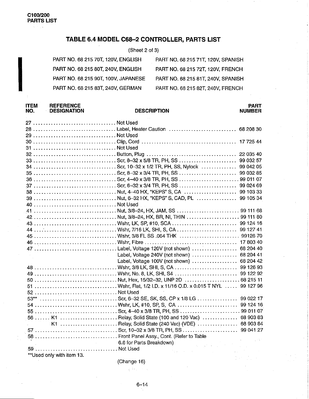
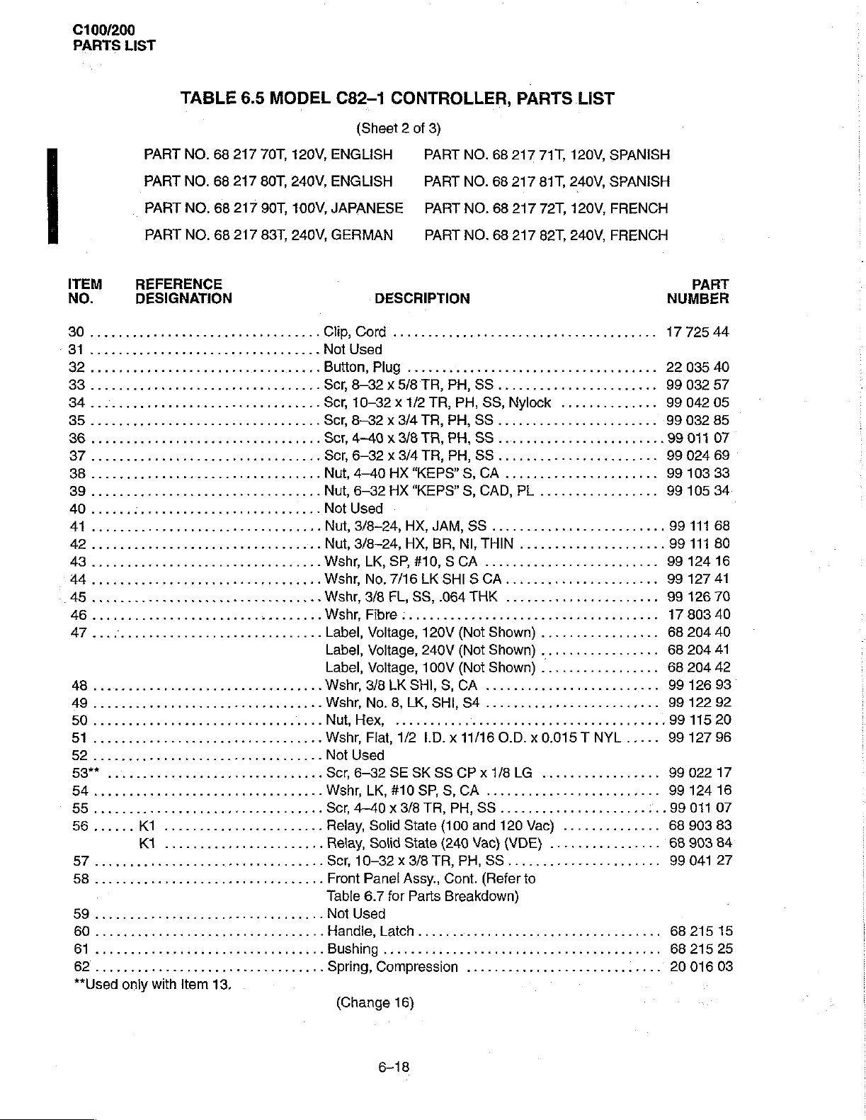
Not
Label,
Clp,
Not
Button,
Scr,
Scr,
Scr
Secr
Scr,
Nut,
Nut,
Not
Nut,
Nut,
Wshr,LK,SP,#10,SCA..........................
Wshr,
Wshr,
Wshr,Fibre......................
Label,
Label,
Label,
Wshr,
Wshr,
Nut,Hex,15/32-32,UNP2D
Wshr,
Not
Scr,
„.
Wshr,
«.
Ser,
..
Relay,
..
Relay,
..
Scr,
Front
6.6
Not
(Change
CONTROLLER,
(Sheet 2 of
3)
PART
PART
PART
PART
DESCRIPTION
Used
Heaïter
Cord
Used
8-32 x 5/8
10-32 x 1/2
8-32X34TR,
4-40X3/8
6-32 x 3/4
4-40
6-32
Used
3/8-24,
3/8-24,
7/16
3/8
Voltage
Voltage
Voltage
3/8
No.
Flat,
Used
6-32
LK,
4-40X3/8TR,PH,SS
10-32 x 3/8
Panel
for
Caution
Plug
.................................,..
TR,
PH,
TR, PH,
PH,
TR,
PH,SS
TR,
PH,
HX,
“KEPS”
HX,
“KEPS”S,
HX,
JAM,
HX,
BR,
LK,
SHI,
S,
FL
SS
.064
120V
240V
100V
LK,
SHI,
S,
8,
LK,
SHI,
1/2
1.D. x 11/16
SF, SK, SS,
#10,
SP,S,
Solid
State
(100
Solid
State
(240 Vac)
TR,
Assy.,
Cont.
Parts
Breakdown)
Used
16)
PARTS
NO.
68
215
NO.
68
215
NO.
68
215
NO.
68
215
..................,........
SS
.......................
SS,
Nylock
SS
..
SS
.......................
S,
CA
CAD,
PL
SS
.
NI,
THIN
.
CA
THK
(not
shown)
(not
shown)
(not
shown)
CA
S4
......................
O.D. x 0.015 T NYL
CP x 1/8
CA
and 120
PH,
(Refer
LG
......,.........,.,.....
し
Vac)
(VDE)
SS............
to
LIST
71T,
120V,
SPANISH
72T,
120V,
FRENCH
81T,
240V,
SPANISH
82T,
240V,
FRENCH
οφ
νο
ενος
..............
eee
νεο
ενω
................
ων
линь»
elele
.....
................
に
し に ーーー
..............
................
Table
ον 99
NUMBER
68
1772544
22
99
99
99
ων
99
99
99
99
ον
99
99
99
99
99126
17
68
68
68
99
99
68
99
99
99
99
68
68
PART
208
30
035
40
032
57
042
05
032
85
011
07
024
69
103
33
105
34
111
68
111
80
124
16
127
41
70
803
40
204
40
204
41
204
42
126
93
122
92
215
11
127
96
022
17
124
16
011
07
903
83
903
84
041 27
C100/200
PARTS
LIST
PART
PART
PART
PART
ITEM
NO.
REFERENCE
DESIGNATION
67..............
0
TAL...
ea
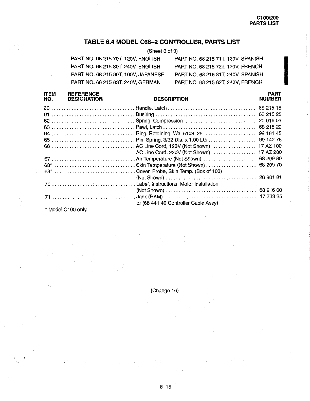
*
Model
C100
only.
TABLE
NO.
NO.
NO.
NO.
1.
68
68
68
68
eee
6.4
215
215
215
215
rr
MODEL
70T,
80T,
90T,
83T,
120V,
240V,
100V,
240V,
C68-2
ENGLISH
ENGLISH
JAPANESE
GERMAN
CONTROLLER,
{Sheet 3 of
3)
PART
PART
PART
PART
DESCRIPTION
Handle,
Bushing
Spring,
Paw,latch......................
Ring,
Pin,
AC
AC
Air
Skin
Cover,
(NotShown)
Label,
(Not
Jack
or
Latch
circenses
Compression
Retaining,
Spring,
Line
Line
3/32
Cord,
Cord,
Temperature
Temperature
Probe,
.....................
instructions,
Shown)
(68
(RAM)
441
................
40
Wal
Dia. x 1.00
120V
220V
(NotShown)
(Not
Skin
Temp.
Motor
Controller
NO.
NO.
NO.
NO.
に に し に に
68
68
68
68
PARTS
215
215
215
215
71T,
72T,
81T,
82T,
LIST
120V,
120V,
240V,
240V,
ee
serrana
............................
5103-25
(Not
{Not
Shown)
....................
LG
...................
Shown)
Shown)
.................
.................
.....................
....................
(Box
of
100)
Installation
ear
Cable
Asey)
トー
r
rn
SPANISH
FRENCH
SPANISH
FRENCH
eee
ekrkee
PART
NUMBER
68
215
68
215
20
016
68
21520
99
181
99
142
17
AZ
17
AZ
68
209
68
209
26
90181
68
216
17
73335
15
25
03
45
78
100
200
80
70
00
(Change
6-15
16)
C100/200
PARTS
LIST
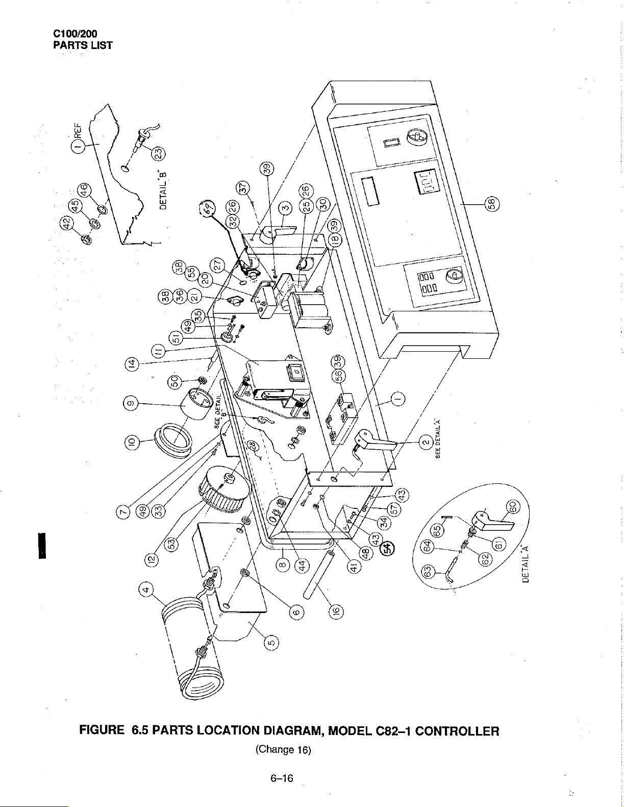
FIGURE
6.5
PARTS
LOCATION
DIAGRAM,
(Change
6-16
MODEL
16)
C82-1
DETAIL'A
CONTROLLER
C100/200
PARTS
LIST
TABLE
PART
NO.
PART
NO.
PART
NO.
PART
NO.
ITEM
NO.
1
2
Qro
4.......
Bo
6
AR
PPP
REFERENCE
DESIGNATION
HTR1
HTR1
HTR1
....................
....................
...............,....
10
26............
DT
28...........
PO
cee
IMPORTANT
on
the
Dual
Number
99
1...
1.
NOTE:
Thermistor,
022
17.
6.5
68
217
68
217
68
217
68
217
rr
k
Z...
eee
eee
eee
220V/240V
item
MODEL
70T,
120V,
80T,
240V,
90T,
100V,
83T,
240V,
κενο
ε
ενω ς Baffle/Plate,
이
디 이 아 이 다
seu
eee
Models
14,
is
Part
C82-1
ENGLISH
ENGLISH
JAPANESE
GERMAN
Chassis
ChassisAssy.,240VUnits........................
Chassis
Chassis,
LatchAssy.,lLeft
εν
Latch
Heater,
Heater,
Heater
Spacer,HeaterPlate
Plate,Stiffener..................................
Plug,
Gasket
Motor
Motor
Impeller
Not
Dual
Not
..
Post,
Not
Power
.
Power
Power
Not
Connector
Receptacle
Not
Thermistor
Not
Circuit
(100
Circuit
(240
Button,
Label,
eee
Not
equipped
Number
CONTROLLER,
(Sheet 1 of 3)
PART
PART
PART
PART
DESCRIPTION
Assy.,120Unit8.........................
Assy.,
100V
Controller
Assy,
Right . e
120V
240V
100V
Heater
Thermostat
Replacement
Replacement
..
Used
Thermistor
Used
Bumper
Used
Transformer
Transformer
Transformer
Used
Used
Used
Breaker,
and
120
Breaker,
Vac
Units)
Plug
Heater
Used
68
(Change
ον
νο
Assy.,
............,..........:.,,,.....
Assy.,
Assy.,
Assy.,
Sgl.
Vac
Sgl.
.................................
..........................,........
Caution
with
Gray
215
28.
16)
PARTS
NO.
68
217
NO.
68
217
NO.
68
217
NO.
68
217
Units
........................
(Weldment)
................................
............................
νο
νο
ον
εν ν ενω
Kit,
120V
Kit,
220V
Hi-Temp
Assy.,
Assy.,
Assy.,
Power
..........................
Air
Temperature
Air
Flow
Pole, 5 amp
Units)
Pole, 5 amp
Oriental
The
Set
.............,.....
ενονοο
...
ec
cece
Alarm
120V
240V
100V
........................
.........................
に に ュー
ルー
Motors. The
Screw
LIST
71T,
120V,
81T,
240V,
72T,
120V,
82T,
240V,
νο
ών
εώς
ence
en
eect
.............
Probe
to
..........
ーー
mount
SPANISH
SPANISH
FRENCH
FRENCH
ον
εν
ον
eee
nee
ーー
トー
Heat Sink
the
heat
.
PART
NUMBER
68
21275
68
21285
68
212
68
215
68
207
68
207
68
208
68
208
68
208
68
208
26
51605
68
204
26
503
1251201
26
501
68
905
68
905
68
205
68
214
68
215
68
206
68
206
68
206
68
205
68
209
68
214
17
BH
17
BH
22
059
68
208
mounted
sink
is
95
10
80
81
25
26
27
20
21
00
00
70
71
45
70
12
71
77
81
81
86
80
150
150
60
30
Part
6-17
C100/200
PARTS
LIST
TABLE
PART
NO.
PART
NO.
PART
NO.
PART
NO.
ITEM
NO.
REFERENCE
DESIGNATION
IAB
iii
68
68
68
68
6.5
217
217
217
217
MODEL
70T,
80T,
240V,
90T,
83T,
C82-1
120V,
ENGLISH
ENGLISH
100V,
JAPANESE
240V,
GERMAN
CHp,
Not
Button,
Scr,
Scr,
..Scr
Scr,
Scr,
…
Nut,
Nut,
Not
Nut,
Nut,
Wshr,
..
Wshr,
Wshr,
Wshr,Fibree:....................................
Label,
Label,
Label,
Wshr,
CONTROLLER,
(Sheet 2 of
DESCRIPTION
Cord
Used
Plug . 2.2.0.0...
8-32 x 5/8
10-32 x 1/2
8-32X34TR,
4-40 x 3/8
6-32 x 3/4
4-40
6-32
Used
3/8-24,
3/8-24,
LK,
No.
3/8 FL,
Voltage,
Voltage,
Voltage,
3/8
PART
PART
—
PART
PART
rra
TR, PH,
TR,
TR,
HX
“KEPS"S,
HX
“KEPS”
HX,
HX, BR,
SP,
#10, S CA
7/16
LKSHISCA....
SS,
120V
240V
100V
LK
SHI,
3)
TR, PH,
JAM,
NO.
PH,
PH,
PH,
S,
NI,
.064
(Not
(Not
(Not
S,
CA
PARTS
68
217
71T,
NO.
68
217
81T,
NO.
68
217
72T,
NO.
68
217
82T,
eee
SS
.....,.,...............
SS,
Nylock
SS
ленин
SS
........................
SS
............,..........
CA
.................,....
CAD,
PL
.................
SS
........................,
THIN
........
.........................
THK
Shown)
Shown)
Shown)
....................
.................
.................
.................
LIST
120V,
SPANISH
240V,
SPANISH
120V,
FRENCH
240V,
FRENCH
eee eee
..............
이 이
디아이
NUMBER
17
22
99
99
+
99
99
99
99
99
99
99
99
68
68
..
99
99
17
68
99
99
99
99
PART
725
035
032
042
032
011
024
103
105
111
111
124
127
126
803
204
204
204
126
122
115
127
44
40
57
05
85
07
69
33
34
68
80
16
41
70
40
40
41
42
93
92
20
96
**Used
only
with
Item
13.
Scr,
6-32
SE
SK SS
Wshr,
LK,#HM0SP,S,CA.........................
Scr,
4-40 x 3/8
Relay,
Relay,
Table
Solid
State
Solid
State
Scr,10-32Xx8/8TR,PH,SS......................
Front
Panel
Assy.,
6.7
for
Parts
Not
Used
Handle,
Bushing
Spring,
(Change
Latch
................
Compression
16)
6-18
CP x 1/8LG
TR,
PH,
(100
(240 Vac)
Cont.
Breakdown)
.................
SS
...................,....
and 120
Vac)
..........,...
(VDE)
(Refer
to
....
99
99
99
68
68
99
68
68
20
022
17
124
16
011
07
903
83
903
84
041 27
215
15
215
25
016
03
C100/200
PARTS
LIST
ITEM
No.
BI
TABLE
PART
NO.
PART
NO.
PART
NO.
PART
NO.
REFERENCE
DESIGNATION
rr
68
68
68
68
6.5
217
217
217
217
MODEL
70T,
80T,
90T,
83T,
120V,
240V,
100V,
240V,
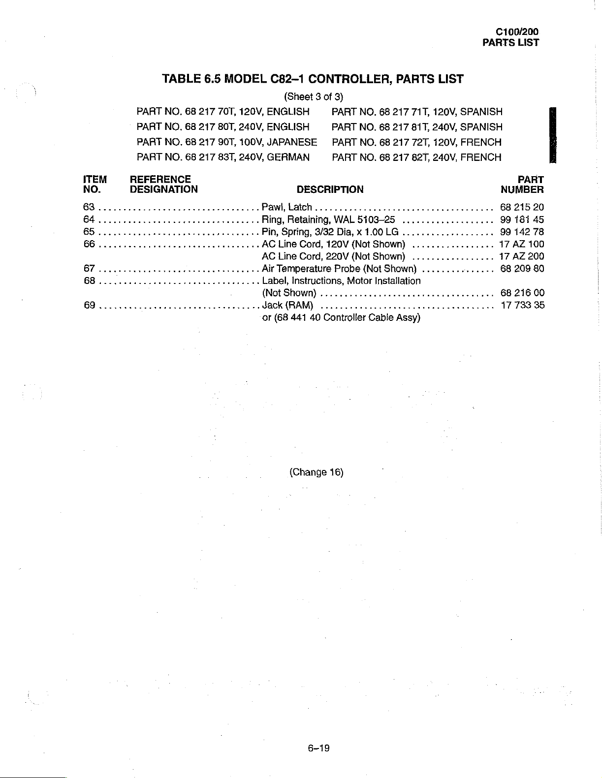
Pawl, Latch
Ring,
Pin,
AC
AC
Air
Label,
(Notshown)
Jack
or
C82-1
(Sheet 3 of 3)
ENGLISH
ENGLISH
JAPANESE
GERMAN
DESCRIPTION
Retaining,
Spring,
Line
Cord,
Line
Cord,
Temperature
Instructions,
(RAM)
(68
441
CONTROLLER,
PART
PART
PART
PART
WAL
5303-25
3/32
Dia, x 1.00
120V
(Not
220V
(Not
Probe
Motor
40
Controller
PARTS
NO.
68
217
NO.
68
217
NO.
68
217
NO.
68
217
LG
Shown)
Shown)
(Not
Shown)
Installation
κενο
Cable
Assy)
LIST
71T,
120V,
SPANISH
81T,
240V,
SPANISH
72T,
120V,
FRENCH
82T,
240V,
FRENCH
EN
...................
...................
.................
.................
ων ρ νεο
ρω
ον
νε
e
ον
nes
PART
NUMBER
68
215
99
181
99
142
17
AZ
17
AZ
68
209
68
21600
17
733
20
45
78
100
200
80
35
(Change
6-19
16)
C100/200
PARTS
LIST
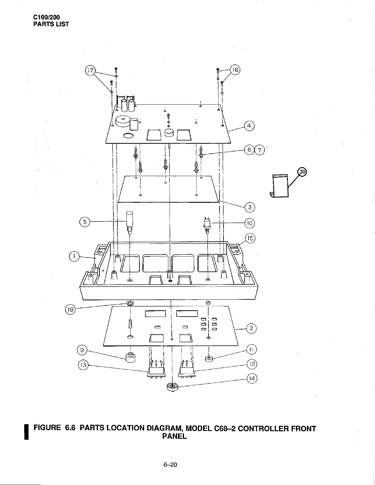
FIGURE
6.6
PARTS
LOCATION
DIAGRAM,
PANEL
6-20
MODEL
C68-2
CONTROLLER
FRONT

C100/200
PARTS
LIST.
ITEM
NO.
TABLE
REFERENCE
DESIGNATION
6.6
MODEL
C68-2
CONTROLLER
PART
NO.
68
PART
NO.
68
PART
NO.
68
PART
NO.
68
PART
NO.
68
DESCRIPTION
Housing,
Nameplate,English..............................
Nameplate,Spanish
Nameplate,French..............................
Nameplate,
Nameplate,Japanese
Display(LED)Board............................
Temp
Cont & Alarm
Power
Switch,
Support,
Scr,
6-32 x 1/4
Not
Used
Guard,
Reset
Guard,
Skin
Air
.
Knob,
..Gasket,FrontPanel
..
Scr,
..
Wshr,
..
Not
. - Nut,
Ribbon
20
Switch,
Switch
Switch
Temp
Temp
Instr.,
6-32 x 3/8
No. 6 LK,
Used
Mounting,
Cable,
Position
211
75T
(English
211
76T
(Spanish
211
77T
(French
211
78T
(German
211
79T
(Japanese
Controller
German
ReplacemenitKit
PCB
(P/O
TR,
Replacement
Assy.
............
Switch
Switch
Assy.
Assy.
Skirted,
RD,
SHI,
Switch
Flat
PCB1
to
FRONT
..............................
.............................
............
...........................
Logic
Item
PH,
SS
..............................
...................,...
Pointer
.............................
PH,SS
S4
(M14x
Flex,
PCB2
PANEL,
Label}
Label)
Label)
Label)
Label)
Board
3)
......................
.................,.......
Crkt
..................
...................
....,.....,............
(P/O
item
Kit
...................
bi
..................
................,.....
1.0)
.......................
0
3)
PARTS
...........
トス
トレ
LIST
ως
ーー
.................
..
..
..
PART
NUMBER
68
215
68
215
6B
215
68
215
68
215
68
215
68
350
68
905
68
901
17
AZ
99
022
68
901
68
210
17
061
68
203
6820371
17
061
68
215
99
023
99
122
17
061
17
730
00
65
66
67
68
69
71T
74
73
534
72
74
75
88
70
89
40
26
19
91
82
*
PCB2
905
74.
Part
No. 68
351
71
for
Model
C68—2
Series
(Change
00
Controllers
16)
6-21
are
no
longer
available.
Order
Retrofit
Kit68
C100/200
PARTS
LIST
|
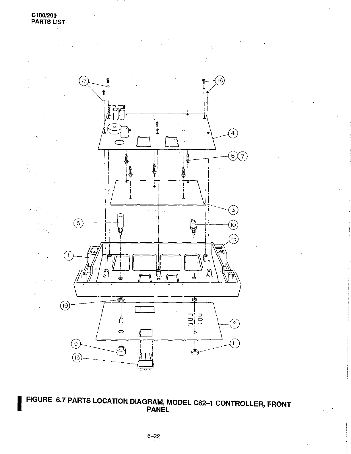
FIGURE
6.7
PARTS
LOCATION
DIAGRAM,
PANEL
MODEL
C82-1
CONTROLLER,
FRONT
6-22
C100/200
PARTS
LIST
ITEM
NO.
1
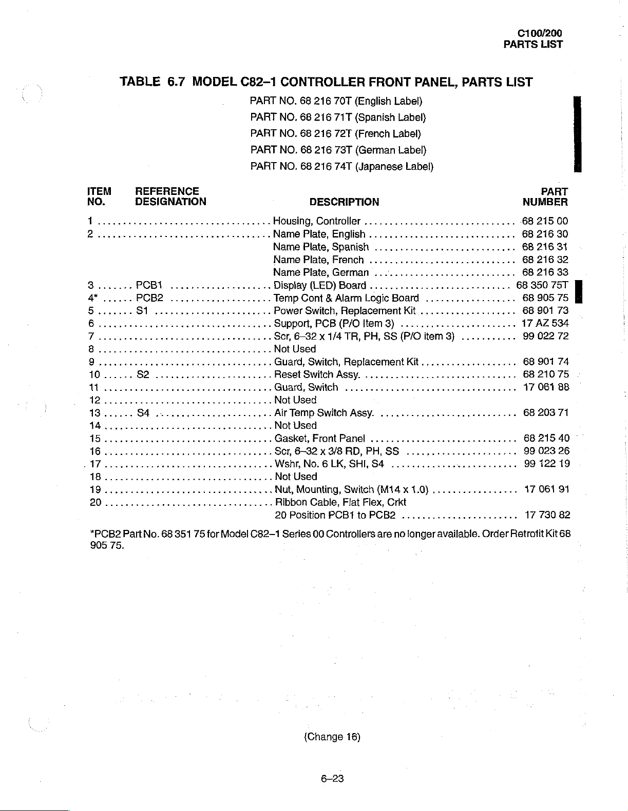
TABLE
REFERENCE
DESIGNATION
6.7
2
8.......
4*......
PCBT
PCB2....................
....................
MODEL
C82-1
CONTROLLER
PART
NO.
68
PART
NO.
68
PART
NO.
68
PART
NO.
68
PART
NO.
68
Housing,Controller...............................
Name
Plate,
Name
Plate,
Name
Plate,
Name
Plate,
Display
Temp
Cont & Alarm
Power
Support,
Ser,
Not
...
Air
...GasketFrontPanel
6-32 x 1/4
Used
Guard,
Reset
Switch
Guard,
Not
Used
Temp
Not
Used
Scr,
6-32 x 3/8
Wshr,
No. 6 LK,
Not
Used
Nut,
Mounting,
Ribbon
20
Position
Switch,
216
70T
(English
216
71T
(Spanish
216
72T
(French
216
73T
(German
216
74T
(Japanese
DESCRIPTION
English
Spanish
French
German
(LED)
Board
Replacement
PCB(P/Oltem3)
TR,
Switch,
Switch
Cable,
Replacement
Assy.
.................,,..............
Switch
RD,
Switch
Flat
PCB1
Assy.
SHI,
Flex,
to
FRONT
PANEL,
Label)
PARTS
LIST
Label)
Label)
Label}
Label)
.......................,....
Logic
Board
Kit
.......................
PH,
SS
(P/O
item
3)
...........
Kit..................,
.........,................,,..
........................,..
.............................
PH,
SS
......................
S4
.........................
(M14 x 1.0}
Crkt
PCB2
.................
.......................
PART
NUMBER
-68
215
68
216
68
216
68
216
68
216
68
350
75T
68
905
68 901 73
17
AZ
534
99
022
68
901
68
210
17
061
68
20371
68
215
99
023
99
122
17
061
17
730
00
30
31
32
33
75
72
74
75
88
40
26
19
91
82
*PCB2
905
75.
Part
No.
68
351
75
for
Model
C82-1
Series
(Change
00
Controllers
16)
6-23
are
no
longer
available.
Order
Retrofit
Kit
68
C100/200
PARTS
LIST
EE
600g
ot
z を せ
a
E
Borekera
OOO エ と
ΤΡΙ
Do
=
に
Aran
quanta
iğ
EE
05%
mo
3-03
Oš
be
n
i 』 ]
.
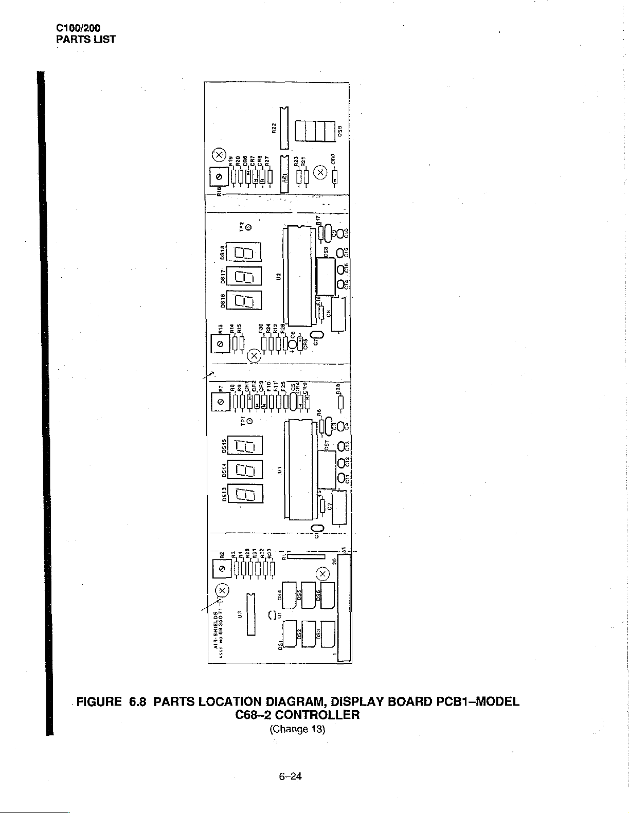
FIGURE
6.8
PARTS
LOCATION
C68-2
DIAGRAM,
CONTROLLER
(Change
6-24
DISPLAY
13)
BOARD
PCB1-MODEL
C100/200
PARTS
LIST
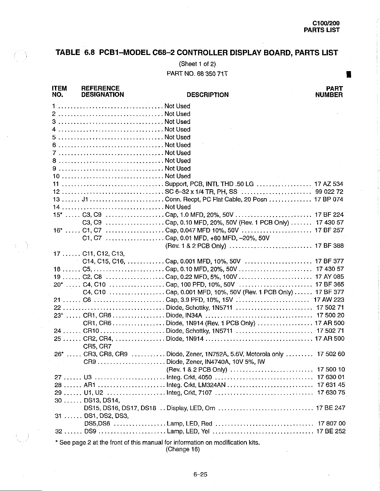
TABLE
ITEM
NO.
9
0
1
1
13......
14
resen
15*
.....
16%
.....
17......
18......
19......
20*
.....
21......
D2
200
23*
.....
24......
25......
26%
.....
27......
28
......
......
29
......
30
31
......
32
......
6.8
PCB1-MODEL
REFERENCE
DESIGNATION
J1.
iii
C3,C9...................
¡o
C1CI...................
C1,C7
C11,
C14, C15,
C5,........,,.........,..,
C2,C8...................
C4,GC10..................
A
C6
CRI,
CRİ,CR6.................
CR10.....................
CR2,CR4,................
CR5,
CR3, CR8,
CR9............,.........
UB
AR1
UT,
DS13, DS14,
DS15,
DS1,
DS5,DS6
DS9
...................
C12,
C13,
C16,
............
нь
.......................
cates
CR6.................
CR7
CRO
...........
eee eee
U2
DS16,
이이
이이
DS17,
이이 이디
DS18
DS2, DS3,
.................
......................
C68-2
CONTROLLER
(Sheet 1 of
PART
NO.
68
2)
350
71T
DISPLAY
BOARD,
DESCRIPTION
Not
Used
Not
Used
Support,
SC
Conn.
Not
Cap,10MFD,2096,50V.........................
Cap,
Cap,
Cap,
PCB,
6-32 x 1/4
Recpt,
Used
0.10
0.047
0.01
PC
MFD,
MFD
MFD,
INTL
TR,
PH,SS
Flat
20%,
10%,
+80
THD
Cable,
50V
50V
MFD,
.50
LG
..................
.......,....,..........
20
Posn
(Rev. 1 PCB
................,......
-20%,
50V
(Revi&2PCBOnİy)..........................
Cap,
0.001
MFD,
10%,
50V
..............,.......
Cap,
0.10
MFD,
20%,
50V
Cap,
0.22
MFD,
5%,
100V
Cap,
100
PFD,
10%,
50V
+
Cap,
0.001
MFD,
10%,
50V
(Rev. 1 PCB
Cap,3.9PFD,109,15V........................
Diode,
Diode,INS4A
Diode,
Diode,
Diode,
Diode,
Diode,
(Rev. 1 8 2 PCB
ων
Integ.
eee
Integ.
Integ,Crkt,7107
..
Display,
Lamp,
Lamp,
Schotiky,
1N914
Schottky,
1N914
Zener,
Zener,
Crkt,
4050
Crkt,
LM324AN
LED,
LED,
Red
LED,
Yel
1N5711
..............................
(Rev. 1 PCB
INS711
...............,.,.......,.........
1N752A,
IN4740A,
Only)
...........,.............
................................
Orn
.................,.......
Only)
..................
....................
5.6V,
Motorola
10V
5%,
IW
...........................
......,............
............................,..
PARTS
..............
Only)
.......
Only)......
0...
...
only
.........
....
LIST
PART
NUMBER
17
AZ
99
022
17
BP
17
BF
17
430
17
BF
17
BF
17
BF
17
430
17
AY
17
BF
17
BF
17AW
17
502
17
50020
17
AR
17502
17
AR
17
502
17
500
17
630
17
631
17
630
17
BE
17
807
17
BE
E
534
72
074
224
57
257
388
377
57
085
365
377
223
71
500
71
500
60
10
01
45
75
247
00
252
*
See
page 2 at
the
front
of
this
manual
for
information
(Change
16)
6-25
on
modification
kits.
C100/200
PARTS
LIST
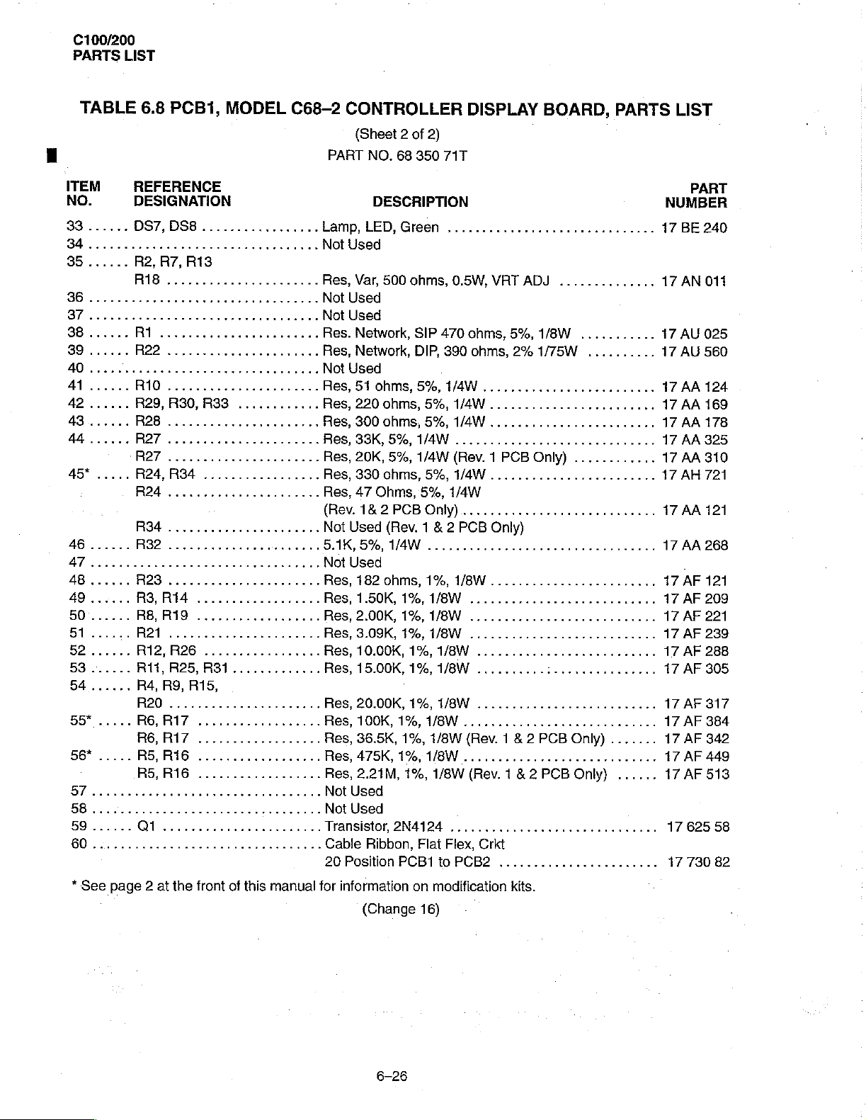
TABLE
ITEM
NO.
33
......
34........
85......
43......
44......
45*.....
46
......
AT
48......
49......
50......
BI...
52......
53
......
54
55*
56*
57
58
59
......
[6
6.8
PCBI,
REFERENCE
DESIGNATION
DS7,DS8.................
R2,
R7,
R18
......................
R28
.........,............
R27
iii
RAT...
R24,R34
R24......................
R34
.................,....
R32
......................
еее
R23......................
R3,R14
R8,R19
RAI
eco
А12,
В26
R11,
А25,
O01....................
MODEL
laaan
R13
.............,..,
нееяянннье я Not
..................
..................
.................
АЗ1.............
C68-2
PART
Lamp,
Not
Res,
Not
Not
Res.
Res,
Not
Res,
Res,
Res,
Res,
Res,
Res,
Res,
(Rev.
Not
5.1K,
Res,
Res,
Res,
Res,
Res,
Res,
Res,
Res,
Res,
Res,
Res,
..
Not
Not
Transistor
Cable
20
CONTROLLER
(Sheet 2 of
NO.
68
350
DESCRIPTION
LED,
Green
Used
Var,
500
ohms,
Used
Used
Network,
Network,
Used
51
220
300
33K,
20K,
330
47
1& 2 PCB
Used
5%,
Used
182
1.50K,
2.00K,
3.09K,
10.00K,
15.00K,
20.00K,
100K,
36.5K,
475K,
2.21M,
Used
Used
Ribbon,
Position
SIP
DIP,
0hmM8,
5%,
ohms,
5%,
ohms,
5%,
5%,
1/4W
5%,
1/4W
ohms,
5%,
Ohms,
5%,
Only)............................
(Rev. 1 & 2 PCB
1/4W
ohms,
1%,
1%,
1%,
1%,
1%,
1%,
1%,
1%,
1/8W
1%,
1%,
1/8W
1%,
2N4124
Flat
PCB1
DISPLAY
2)
71T
............
0.5W,
VAT
470
ohms,
390
ohms,
WIW
1/4W
1/4W
......,.........,............
(Rev. 1 PCB
1/4W
........................
1/4W
Only)
...............,....,......,..2
1/8W
1/8W
.............
1/8W
.............
1/8W
.............
1/8W
..........................
1/8W
..........:...............
1/8W
..........................
............................
1/8W
(Rev. 1 8 2 PCB
............................
1/8W
(Rev. 1 & 2 PCB
............................
Flex,
Crkt
to
PCB2
.......................
BOARD,
이 다 다 이 이 이 이 이 17
ADJ
........,.....
5%,
1/8W
2% 1/75W
Only)
...........
..........
εννοω
............
Only)
Only)
PARTS
ενω τον
.......
......
LIST
PART
NUMBER
BE
17
АМ
17
AU
17
AU
17
AA
17
AA
17
AA
17
AA
17
AA
17
AH
17
AA
17
AA
17
AF
17
AF
17
AF
17
AF
17
AF
17
AF
17
AF
17
AF
17
AF
17
AF
17
AF
17
625
17
730
240
011
025
560
124
169
178
325
310
721
121
268
121
209
221
239
288
305
317
384
342
449
513
58
82
*
See
page 2 at
the
front
of
this
manual
for
information
(Change
6-26
on
modification
16)
kits.
100/200
PARTS
LIST
(This
page
is
intentionally
left
blank.)
6-27
C100/200
PARTS
LIST
πλ
cou
+
>
О,
SUV
129410
ве
Sto
ο
ㅁ
fed
ㅁ
ㅎ
7201
ο
puy
658
ox
seu
KÅR
>
よび
(fo
Яваг
εν
abe
bu
so
”
di
тете
14818
ο
81
=
sry
5
“o
0010
PES
E
E
r
a
jz
O
9
С
а
a
org.
EE
ZN
y
CO
SN
en
그
о
odie
add
Adi
as
tal
E
oa
—
990 650
Za
fio
Sidi
es
e
22
9
σαν
ES
25
=
ии
る
pias
ο
SCD
‘Je
A+
&
Bor
gin
一
一
二
一
vin
[ES
σ
ao
ore
(2866
Eg
[98
988
DER
"E
one
„5
E
|
PRI
4
7
Her
nies
«T+
sin
sin
4D
oro
|
|
EA
A)
som
9601
o
+
č
IND
1194
ar
Sem
gene
ION
NA
|
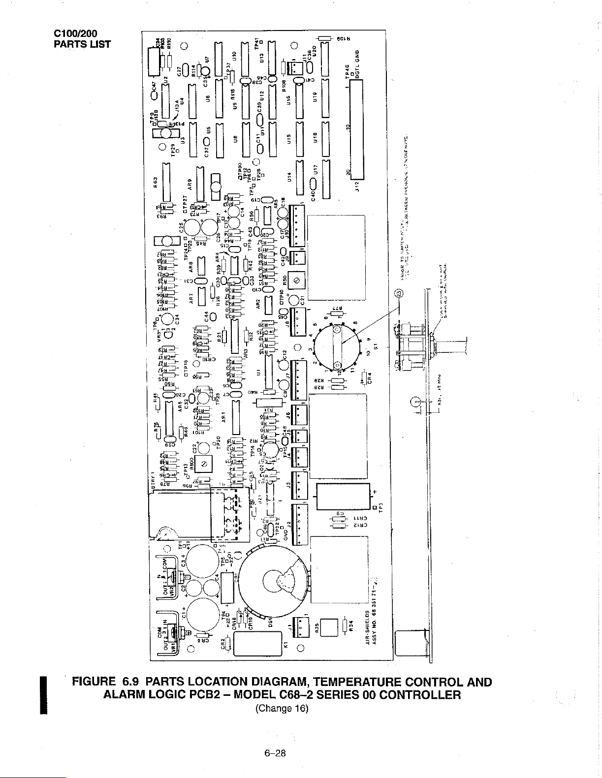
FIGURE
6.9
ALARM
PARTS
LOGIC
LOCATION
PCB2 - MODEL
DIAGRAM,
C68-2
(Change
6-28
TEMPERATURE
SERIES
16)
ne
[PL
196
09
SOTIIHS-YIY
00
JON
ASSY
1
CONTROL
CONTROLLER
U
AND
C100/200
PARTS
LIST
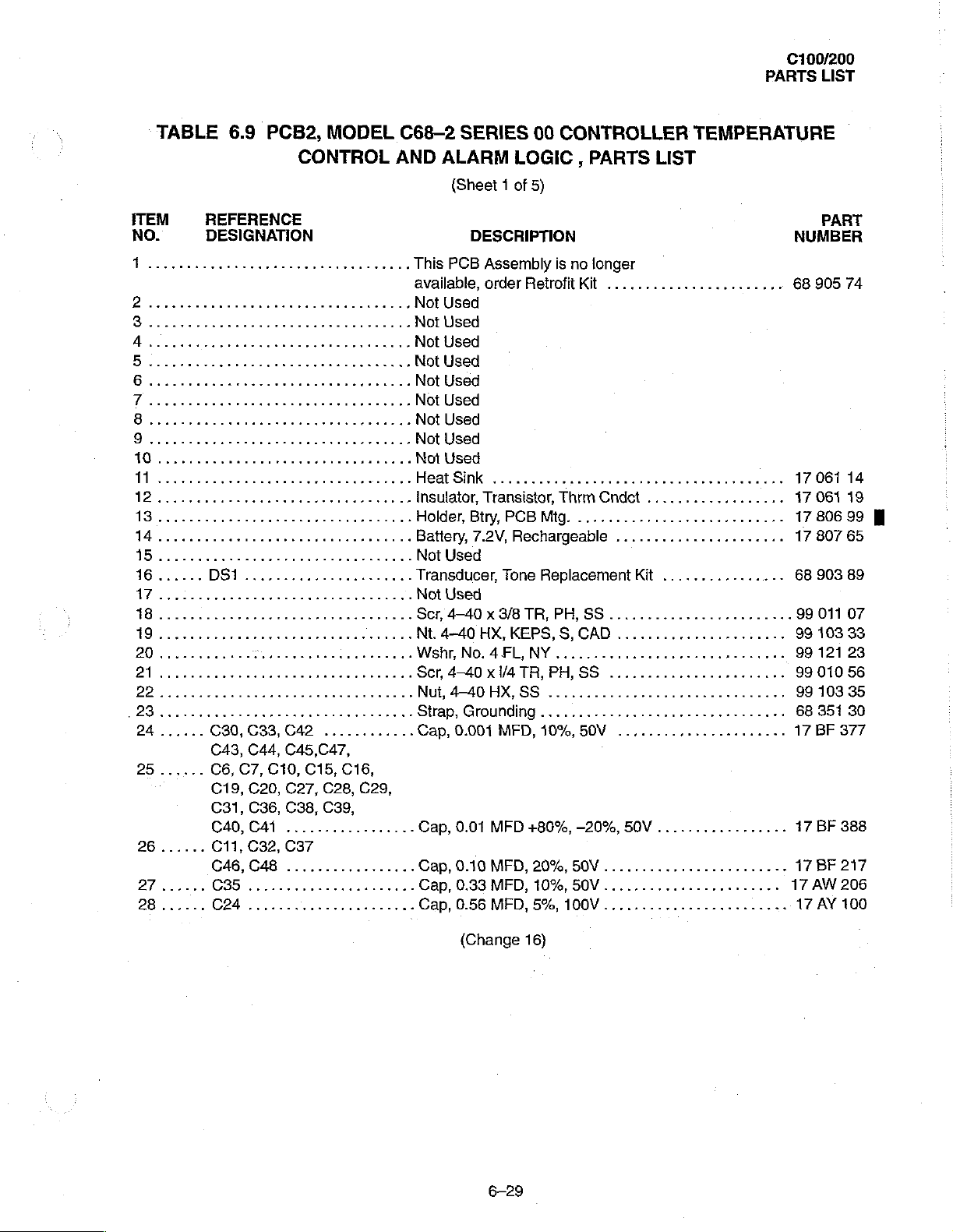
TABLE
ITEM
NO.
1
2
Bo...
25......
26
......
6.9
PCB2,
REFERENCE
DESIGNATION
C30,
C33,
C43, C44,
C6,
C7,
C10,
C19, C20,
C31,
C36,
040,
C41
C11,
C32,
С46,
С48 .................
MODEL
CONTROL
C42
C45,C47,
C15, C16,
C27,
C28, C29,
C38,
C39,
.................
C37
ké
C68-2
AND
..
..
..
..
SERIES
ALARM
(Sheet 1 of 5)
This
PCB
available,
Not
Used
Not
Used
Not
Used
Not
Used
Not
Used
Not
Used
Not
Used
Not
Used
Not
Used
Неа
К
Insulator,
Holder,
Battery, 7.2V,
Not
Used
Transducer,
Not
Used
Scr,
4-40 x 3/8
Nt.
4-40
Wshr,
No. 4 FL,
Scr,
4-40 x 1/4
Nut,
4-40
Strap,
Grounding
Cap,
0.001
Cap,
0.01
Cap,
0.10
Cap,
0.33
Cap,
0.56
00
LOGIC , PARTS
DESCRIPTION
Assembly
order
Retrofit
.....
000
Transistor,
Btry,
PCB
Mig.
Rechargeable
Tone
Replacement
TR,
HX,
KEPS,
NY
TR, PH,
HX,SS
MFD,
MFD
MFD,
MFD,
MFD,
...............,,,............,
10%,
+80%,
20%,
10%,
5%,
CONTROLLER
is
no
longer
Kit
.......................
Thrm
Cndet
.....................,.....
......................
Kit
PH,
SS
..............,,..,.....
S,
CAD
......................
SS
........,.....,,....,..
50V
......................
—20%,
50V
50V
100V
50V
TEMPERATURE
LIST
..........,.......
................
.................
o
....
PART
NUMBER
68
905
17
061
17
061
17
806
17
807
68
903
99
011
99
103
99
121
99
010
99
103
68
351
17
BF
17
BF
17
ВЕ
17
AW
17
AY
74
14
19
99
65
89
07
33
23
56
35
30
377
388
217
206
100
М
(Change
6-29
16)
C100/200
PARTS
LIST
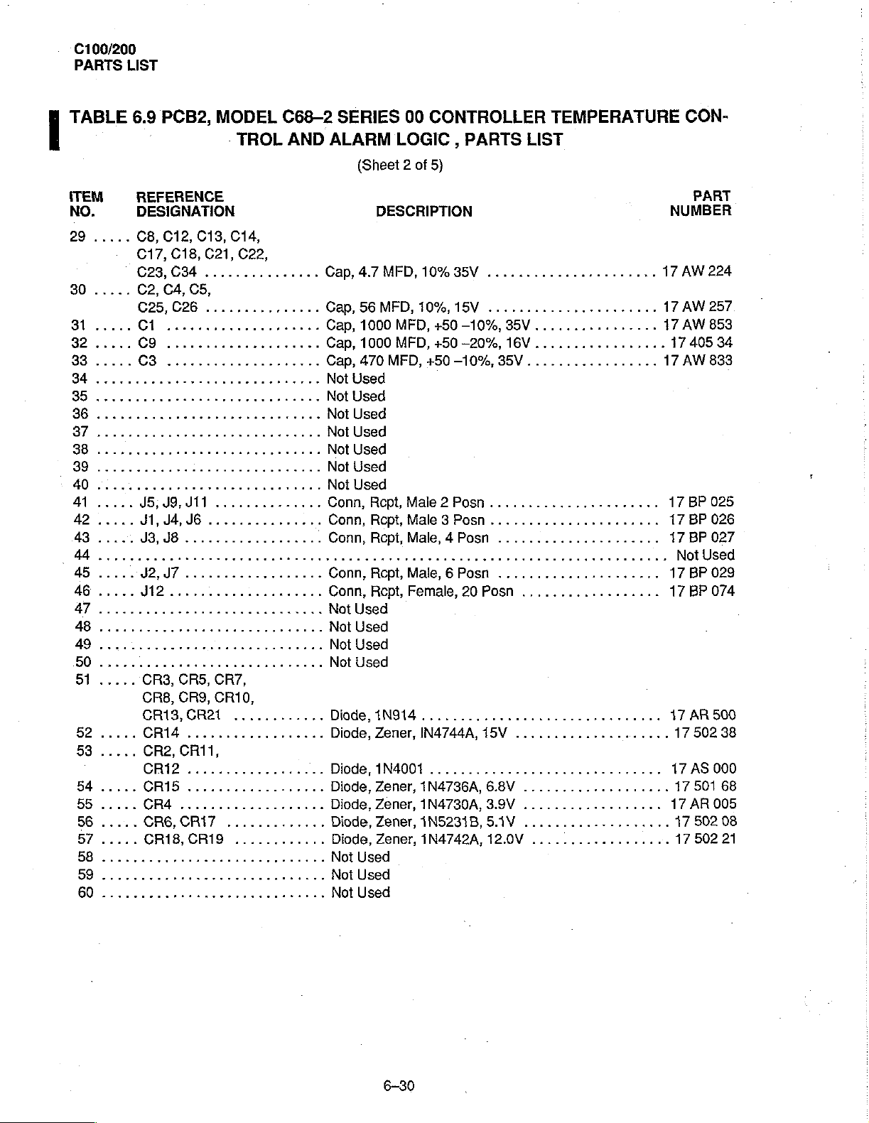
TABLE
ITEM
NO.
29
6. 9 PCB2,
REFERENCE
DESIGNATION
.....
08,
C17,
C23,CM...............
30.....
C2, C4,
C25,C26...............
31.....
32.....
33.....
34
85
eee
μ.ο...
38
39
.... 2 2
40
A
42.....
Bo...
MA
45.....
46.....
47
neue
48
49
..
11
이이 이 이 이 리 이 디 이 이이
50
...
이니
51.....
52.....
53.....
54.....
55.....
56
.....
57
.....
E
LL...
59
see...
60
MODEL
TROL
012,
C13,
C14,
C18,
C21,
C22,
C5,
9
cee
ceeeeeeee
이이
이이
이 이
νν
ων κ ννω
95:09,
Ji,
J3,
11
J4,
JG
JB
Li
...............
iii
YAYI...
12
ν
ων
이
이 이 이 이 이
CR3, CR5, CR7,
CR8,
CR9,
CR10,
CR13,
CRIS
CR2,
CR21
ci
CR11,
............
CR12
CRİS
CR4
CRS,
CR18,CR19
..................
аль...
CRIT
.............
............
C68-2
AND
r
renee
usure
venues
이 이 디
ων
νκ κ κκ
ee
eee
εν ο νεο
이이
이이
SERIES
ALARM
(Sheet 2 of
Cap,
4.7
Cap,
56
っ
Cap,
1000
Cap,
1000
ÓN
Сар,
470
Not
Used
Not
Used
Not
Used
А
Not
Used
Not
Used
디 이
Not
Used
ων
Not
Used
Conn,
Conn,Rept,Male3Posn......................
Conn,
passe
Conn,
ees
Conn,
Not
Used
Not
Used
이
Not
Used
Not
Used
Diode,1N914...............................
Diode,
ーー
Diode,
Diode,
Diode,
Diode, Zener,
Diode,Zener,iN4742A,12.0V
Not
Used
Not
Used
Not
Used
00
LOGIC,
DESCRIPTION
MFD,
10%
MFD,
10%,
MFD,
MFD,
MFD,
Rept,
Male 2 Posn
Rept,
Male, 4 Posn
cesser
Rcpt,
Male, 6 Posn
Rcept,
Female,
Zener,
1N4001
Zener,
Zener,
IN4744A,
1N4736A,
1N4730A,3.9V
1N5231B,5.1V
CONTROLLER
PARTS
5)
85V
.............,........
15V
.....................,
+50
-10%,
+50
-20%,
+50
-10%,
eee
20
..............................
35V
16V
35V.................
......................
.....................
amaaan
..................,..
Posn
15V
6.8V
TEMPERATURE
LIST
................
.............,...
..................
....................
...................
..................
...................
..................
nana»
CON-
NUMBER
17
AW
17
AW
17
AW
17
405
17
AW
17
BP
17
BP 026
17
BP
Not
17
BP
17
ВР 074
47
АВ
17
17
AS
17
17
AR
17
17
PART
224
257
853
34
833
025
027
Used
029
500
502
000
501
005
502
502
38
68
08
21
6-30
 Loading...