

Air-Shields C100, C200, QT Service manual
ーー
7
βλ
ο
'
:
Service
Manual
PET
INFANT
INCUBATOR
Air-Shields
®
|
Models
Includes:
C100
Hood
and
Controller,
V
.
and
Shell
Models
C200
Assembly,
C68—2/2E,
Vickers
Medical
and
Models
C82—1/1E
QT®
C100/200-2
LIMITED
The
product
being
of
shipment
During
There
This
This
consequential
"The
thereafter.
warranty
dealers.
from
All
consumable
Calibrations
the
warranty
will
be no
warranty
1.
Damage
2.
The
customer
3.
The
customer
4.
Sale
warranty
Accreditation
To
period.
described
Air-Shields,
and
are
considered
period
labor
is
rendered
to
the
or
service
is
in
lieu
damages
Manual
comply
with
This
in
disposable
any
charge
void
unitis
fails
to
uses
any
is
performed
of
ail
other
including
for
this
service
this
manual
Hatboro,
for
incurred
maintain
Hospitals
standard, we
can
with
products
normal
defective
replacing
and
Air-Shields
as a result
the
parts,
accessories,
by an
warranties,
loss
of
requires
be
performed
WARRANTY
is
warranted
the
maintenance
parts
the
unit
non-certified
expressed
use,
recommend
against
following
are
guaranteed
and
other
than
parts
within
cannot
be
of
mishandling.
in a proper
or
fittings
property
each
piece
that
by
certified
or
damage,
defects
in
exceptions.
to
be
free
are
not
included
those
listed
above
the
continental
held
liable
for
manner.
not
specified
service/dealer
implied,
of
equipment
you
technicians
agency.
and
Air-Shields
or
personal
participate
materials
from
conditions
is
through
defects
in
the 1 year
will
U.S.
or
sold
injury
to
be
tested
in
our
or
be
Preventive
our
workmanship
upon
shipment
warranty.”
replaced
resultant
by
shail
resulting
therefrom
Air-Shields.
in
no
from
prior
to
Maintenance
Product
for
at
no
charge
event
be
breach
initial
use
Service
one
year
only.
if:
liable
of
and
Program
Group
from
the
to
the
customer.
for
incidental
warranty.
at
!east
annually
during
and
authorized
date
es
or
the
For
instrumentation
800-523-2404.
/
Cat.
A123456789
E123456789
AN
3
i
optimal
No.
oO
performance,
specialists
}Customers
68
990
13-17
Gew
id
A
<
product
are
located
outside
4
3D
service
throughout
the
U.S.
SERVICE
should
be
performed
the
United
should
contact
only
by
States
and
their local
qualified
factory-authorized
are
dispatched
service
personnel.
for
Air-Shields
Product
required
Printed
Change
Change
Change
Change
Change
Change
Change
Change
Change
Change
Change
Change
Change
Change
Change
Change
maintenance
in
01
02
03
04
05
06
07
08
09
10
11
12
13
14
15
16
Service
distributor
U.S.A.,
for
12/82
10/84
11/85
10/86
11/93
Group
by
calling
service.
9/83
6/85
4/86
4/87
9/87
1/88
4190
1/91
3/92
1/93
3/94
4/95
글
. :
330
Jacksonville
Road,
Hatboro,
Vickers
PA
19040
PLEASE
READ
Please
Since
component
incorporated
separate
package.
to
THIS
check
Air—Shields
sheets
Changed
the
changed
MANUAL
the A
improvements
into
MODIFICATIONS
TO
MAINTAIN
CANNOT
OPERATION
OR
ASSUME
OF
MODIFICATION.
NOTE
Some
parts
used
this
manual.
function
of
This
the
page
for
Vickers
the
printed
at
the
rear
material
material,
as
CONTAINS
SHOULD
YOUR
WARRANTY
RESPONSIBILITY
THIS
EQUIPMENT
ON
in
your
equipment
sometimes
equipment.
change
conducts a continuous
are
manuals.
of
on
shown
PROPRIETARY
BE
information.
sometimes
When
the
manual
each
page
on
the
PERFORMED
AND
FOR
WHICH
product
incorporated
this
occurs,
or
under
of
text
is
indicated
right.
INFORMATION.
ONLY
TO
AVOID
ANY
CONDITIONS
MAY
RESULT
separate
BY
REPLACEMENT
may
be
occurs
Order
due
to
the
part
NOTE:
ALSO
different
difficulty
listed
than
in
in
the
SEE
parts
Parts
PAGE
improvement
into
equipment
changed
cover
by a vertical
REPAIRS
QUALIFIED
CREATING
FROM
those
which
procurement,
List.
2.
program,
before
material
in
the
form
bar
in
the
AND
SERVICE
SAFETY
HAZARDS.
AFFECTING
UNAUTHORIZED
PARTS
appear
but
in
does
circuit
and
they
can
is
provided
of a change
margin
next
AUTHORIZED
PERSONNEL
WE
THE
PROPER
REPAIR
the
Parts
List
not
alter
be
on
of
the
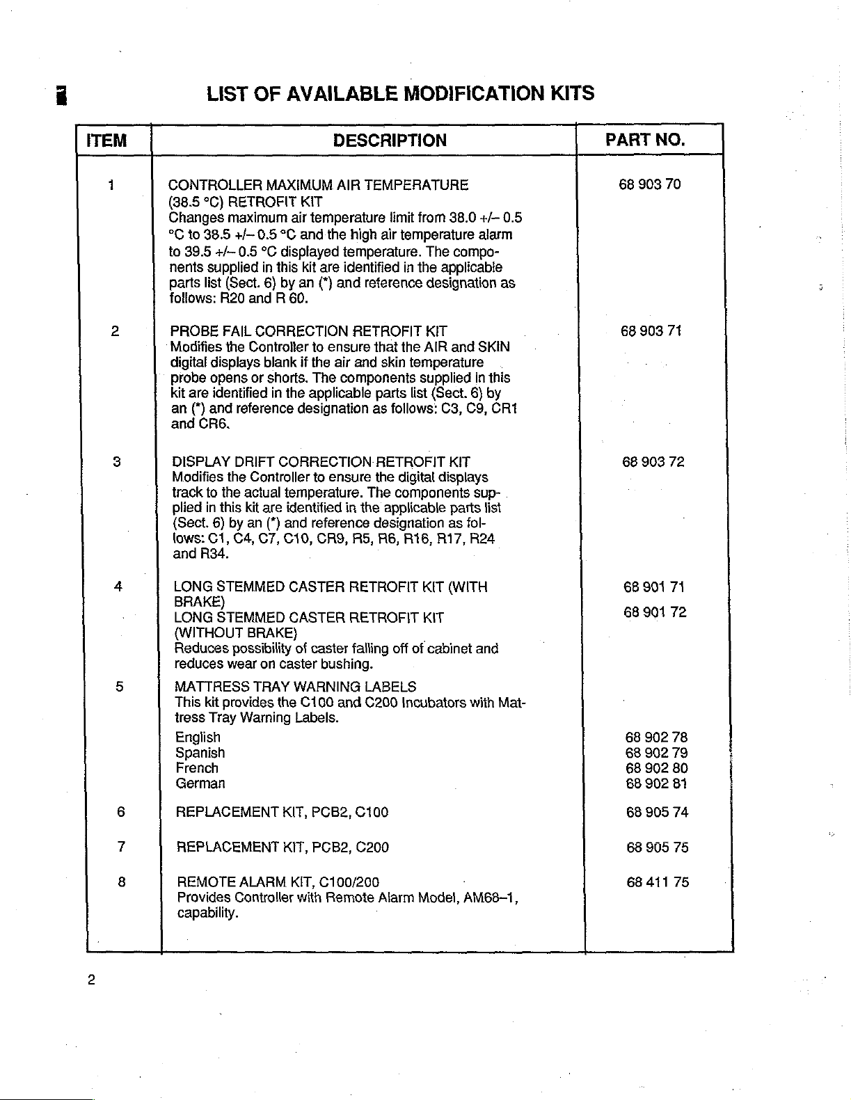
ITEM
LIST
OF
AVAILABLE
MODIFICATION
DESCRIPTION
KITS
PART
NO.
1
2
3
4
5
CONTROLLER
(38.5
°C)
RETROFIT
Changes
°C
to
39.5
nents
parts
follows:
PROBE
Modifies
digital
probe
kit
an
and
DISPLAY
Modifies
track
plied
(Sect.
lows:
and
LONG
BRAKE)
LONG
{WITHOUT
Reduces
reduces
MATTRESS
This
tress
English
Spanish
French
German
to
38.5
+/—
supplied
list
(Sect.
R20
FAIL
the
displays
opens
are
identified
(*)
and
CR6.
the
to
the
in
this
6)
C1,
R34.
STEMMED
STEMMED
wear
kit
provides
Tray
maximum
+/- 0.5
0.5
reference
DRIFT
by an
C4,
possibility
MAXIMUM
air
°C
°C
displayed
in
this
6)
by
an
and R 60.
CORRECTION
Controller
blank
or
shorts.
in
the
designation
CORRECTION
Controller
actual
temperature.
kit
are
identified
(*)
and
C7,
C10,
CASTER
CASTER
BRAKE)
of
on
caster
TRAY
WARNING
the
Warning
Labels.
AIR
KIT
temperature
and
the
high
temperature.
kit
are
identified
(*)
and
RETROFIT
to
ensure
if
the
air
and
The
components
applicable
to
ensure
in
the
reference
CRS,
AS, A6,
RETROFIT
RETROFIT
caster
falling
bushing.
C100
and
TEMPERATURE
limit
from
air
temperature
The
in
the
applicabie
reference
that
skin
parts
as
RETROFIT
the
The
applicable
designation
LABELS
C200
designation
KIT
the
AIR
temperature
supplied
list
(Sect.
follows:
digital
components
off
C3, C9,
displays
R16, R17,
KIT
KIT
of
cabinet
Incubators
38.0
+/-
alarm
compo-
and
SKIN
in
this
6)
by
CR1
KIT
sup-
parts
list
as
fol-
R24
(WITH
and
with
0.5
as
Mat-
68
68
68
68
68
68
68
68
68
903
903
903
901
17
901
902
902
902
902
70
71
72
71
72
78
79
80
81
6
7
8
REPLACEMENT
REPLACEMENT
REMOTE
Provides
capability.
ALARM
Controller
KIT,
KIT,
KIT,
with
PCB2,
PCB2,
C100
C200
C100/200
Remote
Alarm
Model,
AM68-1,
68
905
74
68
905
75
68
411
75
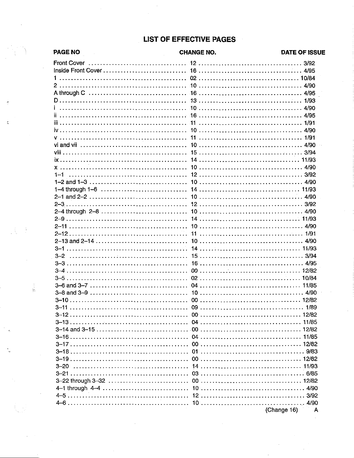
LIST
OF
EFFECTIVE
PAGES
PAGE
1-2
1-4
2
NO
and
1-3
through
............,....,,,..,,.........,
1-6
..............................
CHANGE
WD
W
1
NO.
ess
DATE
esssssuse
rr
OF
11/93
4/90
ISSUE
3-22
4-1
through
45...
ererken
through
3-32
4-4
............................
00
erne
(Change
16)
12/82
A
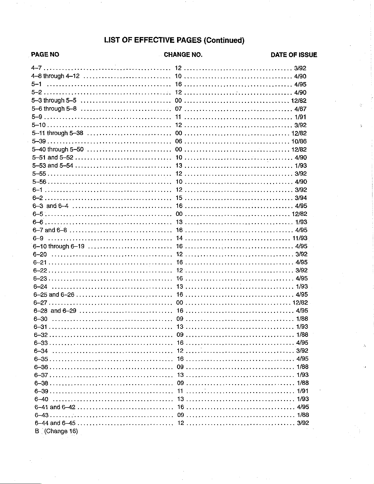
LIST
OF
EFFECTIVE
PAGES
(Continued)
PAGE
5-3 through
6-7
NO
5-5
5—-6through5-B8
人
5-40
EEES
5-53
through
and
and6-8
5-50
5-54 し に し に に rro
....
CHANGE
.....................
0.0011
IN
NO.
DATE
OF
ISSUE
B
(Change
16)
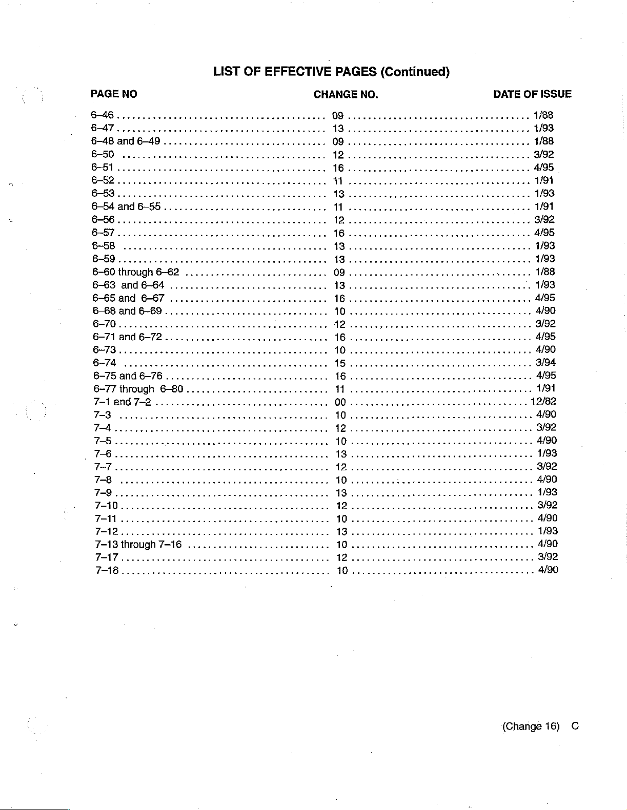
PAGE
6-60
through
6-63
6-6Sand
6-68
апа
LIST
OF
EFFECTIVE
NO
6-62
and
6-64 ..............
6-67...............................
6-69
..................
уе
зуиианьн,
PAGES
CHANGE
(Continued)
NO.
DATE
OF
ISSUE
6-75
and
6-77
7-1
7-43
7-17
6-76
through
and7-2...........
through
...........
6-80
7-16
.
kkkkee
(Change
16)
ο

(This
page
is
intentionally
left
blank.)
D
(Change
13)
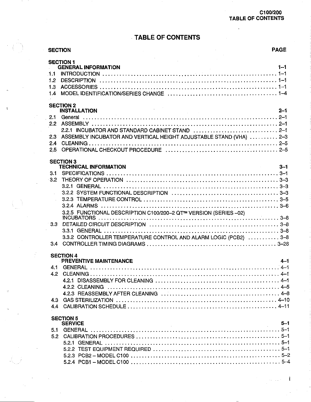
C100/200
TABLE
OF
CONTENTS
SECTION
5.2.5
5.2.6
5.2.7
5.2.8
5.3
TROUBLESHOOTING
5.3.1.
5.3.2
5.3.3
5.3.4
5.4
REMOVAL
©
541
5.4.2
5.4.3
5.4.4
5.45
5.4.6
SECTION
PARTS
6.1
GENERAL
PCB2-
PCB1-MODELC200
LEAKAGE
OXYGEN
СЕМЕВАЁ
TEST
TROUBLESHOOTING
TROUBLESHOOTING
GENERAL..................
CONTROLLER
PCB2
PCB1
POWER
OXYGEN
6
LIST
MODEL
EQUIPMENT
AND
AND
....,,.....,444.444
C200
に
СУВВЕМТ
CONCENTRATION
..........
REPLACEMENT
SILENCE/RESET
INPUT
ТЕЗТ$
2.0
REQUIRED
PROCEDURES
THE
FRONT
VALVE
PANEL
FILTER
TABLE
ACTUATOR-VHA
PROCEDURES
444444
OF
........
TESTS
SWITCHES.........
CARTRIDGE
CONTENTS
ii
STAND
eee
eus
K
ss
issues
P
............................,
K K K
O
P K K K K
K K K
ne
tern
K K
Kk
nkknnnee
K
5-10
5-51
6-1
6—1
SECTION
6
7.1
7
SCHEMATIC
GENERAL
DIAGRAMS
K S
K
P K K
K K K K P K K
KK
7-1
7-1
ii
(Change
16)
LIST
OF
TABLES
TABLE
OF
C100/200
CONTENTS
TABLE
TABLE
TABLE
TABLE
TABLE
TABLE
TABLE
TABLE
TABLE
TABLE
TABLE
TABLE
TABLE
TABLE
TABLE
TABLE
TABLE
TABLE
TABLE
.
TABLE
TABLE
TABLE
TABLE
TABLE
TABLE
TABLE
TABLE
1.1
SERIES
1.2
SERIES
1.3
SERIES
3.1
SPECIFICATIONS . ..
3.2
SPECIFICATIONS
6.1
HOOD
6.2
ACCESS
6.3
SHELL
6.4
MODEL
6.5
MODEL
6.6
MODEL
6.7
MODEL
6.8
PCB1-MODEL
6.9
PCB2,
AND
6.10
ALARMLOGIC,PARTSUIST.......................
6.11
6.12
AND
6.13
CONTROL
6.14
6.15
6.16
6.17
6.18
6.19
6.20
6.21
CHANGE — C68-2
CONTROLLER
CHANGE-C82-1CONTROLLER
CHANGE — C100/200-2
..
..
. . 2 2.
VHA
STAND
ASSEMBLY
PANEL
ASSEMBLY
C68
C82
C68
C82
MODEL
ALARM
PCB2,
РСВ1,
PCB2 — MODEL
POB2-1
CABINET
ACCESSORY
VHA STAND,
MODEL
MODEL
ALARMLOGIC,
MODEL
ANDALARMLOGIC,PARISLIST
STAND
I.V.
POLE
ASSEMBLY,
INNER
C100/200-2
C100/200-2
PARTS
COLUMN
LIST,
(SERIES
ASSEMBLY
AND
CONTROLLER,
CONTROLLER,
CONTROLLER
CONTROLLER
C68
CONTROLLER
C68-2
LOGIC,
SERIES
SERIES
PARTS
C68-2
C82-1
C82—1
C82-1
ASSEMBLY
SHELF
PARTS
ASSEMBLY,
C100/200—2
01),
(SERIES
DECK
PARTS
PARTS
FRONT
FRONT
SERIES
LIST
SERIES
CONTROLLER
SERIES
PARTSLIST.................
SERIES
ASSEMBLY,
PARTS
LIST
......................,4444.4..
02
ACCESS
02
HOOD
SERIES
HOOD
AND
니니 이 ドド
(OPTION)
PARTS
LIST
01),
ASSEMBLY,
LIST
LIST
PANEL,
PANEL,
DISPLAY
00
CONTROLLER
01
CONTROLLER
DISPLAY
00
CONTROLLER
01
CONTROLLER
.................
PARTS
LIST
(ACCESSORY)
PARTS
ASSEMBLY
LIST
PANEL
02
MAIN
PAGE
......................
........................
SHELL
ーー
ASSEMBLY
トド
トー
トト
..................
トー
.........................
...............,.................
PARTS
PARTS
LIST
..................:......
LIST
........................
....................................
.....,..............................
PARTS
PARTS
BOARD,
LIST
ASSEMBLY
DECK
LIST
......................
LIST
......................
PARTS
TEMPERATURE
TEMP.
BOARD,
TEMPERATURE
TEMPERATURE
...............................
(ACCESSORY)
..........................
....................,..,,........
.................,...............
ASSEMBLY
LIST
CONT.
PARTS
0
.....
ннеен
нии
トピ
トー
3-1
0...
6-13
6-17
8-21
6-23
...............
CONTROL
a
AND
elena
LIST
....,.......
CONTROL
eee 시 이 이 기 아 이
ενω κ ων
.................
44e
6-25
6-29
6-35
6-41
6-45
6-51
6-57
se
1-4
1-4
1-4
3-3
6-3
6-7
6-9
6-59
6-61
6-65
6-69
6-71
6-75
iii
LIST
OF
ILLUSTRATIONS
(CONTINUED)
TABLE
OF
CONTENTS
C100/200
FIGURE
FIGURE
FIGURE
FIGURE
FIGURE
FIGURE
FIGURE
FIGURE
FIGURE
FIGURE
FIGURE
FIGURE
FIGURE
FIGURE
FIGURE
FIGURE
FIGURE
FIGURE
FIGURE
|
FIGURE
FIGURE
FIGURE
FIGURE
FIGURE
FIGURE
FIGURE
FIGURE
FIGURE
FIGURE
FIGURE
FIGURE
FIGURE
FIGURE
5.2
PCB1
(MODEL
ADJUSTMENTS
5.3
PCB2
(MODEL
C100),
.......:...........
C200),
ADJUSTMENTS
5.4
PCB1
(MODEL
ADJUSTMENT
5.5
OXYGENİNPUTVALVE
5.6
VHA
STAND
5.7
VHA
STAND
5.8
ΙΝΘΕΗΤΙΟΝ
6.1
6.2
PARTS
PARTS
LOCATION
LOCATION
(SERIES
6.3
6.4
6.5
6.6
6.7
6.8
PARTS
PARTS
PARTS
PARTS
PARTS
PARTS
LOCATION
LOCATION
LOCATION
LOCATION
LOCATION
LOCATION
WIRING
WIRING
ΟΕ
01)
C200),
200.0000
ΘΙΒΡΙΝΘ.....
eee
DIAGRAM,
CONTROLLER...........
6.9
PARTS
LOGIC
6.10
LOGIC
6.11
PARTS
PARTS
LOCATION
PCB2 ~ MODEL
LOCATION
PCB2 — MODEL
LOCATION
CONTROLLER
6.12
PARTS
LOCATION
LOGİC
6.13
PARTS
LOGIC
6.14
6.15
PARTS
PARTS
LOCATION
PCB2-1
LOCATION
LOCATION
MODEL
(ACCESSORY)
6.16
PARTS
LOCATION
(ACCESSORY)
6.17
PARTS
6.17
PARTS
6.18
PARTS
6.19
PARTS
PANEL
6.20
PARTS
6.21
PARTS
7.1
C68
SERIES
7.1
C68
SERIES
7.1
C68
SERIES
LOCATION
LOCATION
LOCATION
LOCATION
ASSEMBLY
LOCATION
LOCATION
CONTROLLER
00
(Sheet 1 of3)
CONTROLLER
00
{Sheet 2 of
CONTROLLER
00
(Sheet 3 of
LOCATION
LOCATION
cece
LOCATION
ccc
ASSEMBLY
OF
OF
cece
OF
ccc
cece cece
TEST
TEST
TEST
.......................
DIAGRAM — 120V
DIAGRAM — 220/240
«ον
DIAGRAM,
DIAGRAM,
HOOD
ASSEMBLY
ACCESS
SHELL
DIAGRAM,
DIAGRAM,
DIAGRAM,
DIAGRAM,
DIAGRAM,
DIAGRAM,
C68
DIAGRAM,
C68-2
DIAGRAM,
2.
2 2 2 2 2 이 이이다 다 디디
DIAGRAM,
DIAGRAM,
C82-1
MODEL
MODEL
MODEL
MODEL
DISPLAY
TEMPERATURE
SERIES
00
TEMPERATURE
SERIES
DISPLAY
TEMPERATURE
TEMPERATURE
SERIES
DIAGRAM, CABINET
DIAGRAM,
ACCESSORY
に に eee
DIAGRAM,
IV.
POLE
cece
DIAGRAM,
DIAGRAM,
DIAGRAM,
DIAGRAM,
に
DIAGRAM,
DIAGRAM,
SCHEMATIC
SCHEMATIC
3)
SCHEMATIC
VHA
VHA
INNER
C100/200-2
に
C100/200-2
C100/200-2
20.
STAND
STAND
DIAGRAM — C68-2
DIAGRAM — C68-2
DIAGRAM — C68-2
3)
POINTS
AND
IE
cee
cece
UNITS
ενω
POINTS
POINTS
eee
UNITS.
εν
AND
eee
te
nett
AND
pete e ent
..........
..................
ονωνων
εν
εν
(SERIES
PANEL
ASSEMBLY
C68
C82
C68
C82
BOARD
ASSEMBLY
AND
DECK
CONTROLLER
CONTROLLER
CONTROLLER,
CONTROLLER,
PCB1-MODEL
CONTROL
CONTROLLER
CONTROL
01
CONTROLLER . лень
BOARD
PCB1-MODEL
디 디 이 니 a
CONTROL
R R
CONTROL
01
CONTROLLER
STAND
ASSEMBLY
SHELF
ASSEMBLY
ASSEMBLY
cece
cence
tenet b eaten
(Sheet 1 af
(Sheet 2 of
COLUMN
ASSEMBLY
SERIES
иен
SERIES
SERIES
02
инете
02
02
CONTROLLER
CONTROLLER
CONTROLLER
ete
eee
ee
eet
tenet
eee
nen
ene
K
...
ένο ν εως
01)
εν εν
ενος
νο
..........,.......
ASSEMBLY
........
....................
....................
FRONT
FRONT
PANEL.......
PANEL.......
C68
AND
ALARM
..........
AND
iii
ALARM
C82
AND
ALARM
0
AND
secs
ALARM
ké
.....................
..................
-
pete
netenenes
2)
...........,....,...
2)
...............,....
..................
ACCESS
HOOD
MAIN
ASSY............
DECK
|
ея
итяеенчианткь
ASSEMBLY
n
lala
PAGE
5-52
5-53
5-54
ον
5-56
6-12
6-16
6~20
6~22
ーー
6-28
6-34
6-40
6-44
..
ων
5-5
5-7
.
5-8
6-2
6-6
6-8
6-2
6-50
6-56
6-58
6-60
6-63
6-64
6-68
6-72
6-74
6-78
73
7-4
LIST
OF
FLOWCHARTS
(CONTINUED)
TABLE
OF
CONTENTS
C100/200
FLOWCHART
FLOWCHART
FLOWCHART
FLOWCHART
FLOWCHART
FLOWCHART
FLOWCHART
FLOWCHART
FLOWCHAHT
FLOWCHART
FLOWCHART
-
FLOWCHART
FLOWCHART
FLOWCHART
FLOWCHART
FLOWCHART
FLOWCHART
FLOWCHART
FLOWCHART
FLOWCHART
:
FLOWCHART
FLOWCHART
FLOWCHART
FLOWCHART
FLOWCHART
FLOWCHART
FLOWCHART
FLOWCHART
FLOWCHART
FLOWCHART
5.3
DISPLAY
5.4
SET
5.4
SET
5.4
SET
5.5
SET
5.5
SET
5.5
SET
5.6
ONE
5.7
15
5.8
AIR
(Sheet1
5.8
AIR
(Sheet20f5)........................
5.8
AIR
(Sheet 3 of
5.8
AIR
(Sheet40f5)...................
5.8
AIR
TROUBLESHOOTING
TEMP
TEMP
TEMP
TEMP
TEMP
MINUTE
AND
of5)
AND
AND
AND
AND
LOW
ALARM
LOW
ALARM
LOW
ALARM
HIGH
ALARM
HIGH
ALARM
TEMP
HIGH
ALARM
HOUR
TIMER
TIMER
SKIN*
5)
............,......,......,.....,
SKIN
SKIN
SKIN
SKIN
PROBE
PROBE
PROBE
PROBE
PROBE
TROUBLESHOOTING
TROUBLESHOOTING
TROUBLESHOOTING
TROUBLESHOOTING
TROUBLESHOOTING
TROUBLESHOOTING
TROUBLESHOOTING
TROUBLESHOOTING
ALARMS
ALARMS
ALARMS
ALARMS
ALARMS
(Sheet50f5)
5.9
AIR
FLOW
5.9
AIR
FLOW
5.8
AIR
FLOW
5.10
HIGH
(Sheet1
5.10
(Shet2of3)......................
5.10
(Sheet 3 Of 3)
5.11
5.11
5.11
5.11
5.12 38.5
of3)
HIGH
HIGH
HEATER
HEATER
HEATER
HEATER
5.13-POWER
5.14
OXYGEN
5.14
OXYGEN
5.15
INSUFFICIENT
ALARM
ALARM
ALARM
AIR
TEMP
iii
AIR
TEMP
AIR
TEMP
°C
oo.
AIR
FAILURE
cece
CIRCUITRY
CIRCUITRY
CIRCUITRY
CIRCUITRY
TEMP
CONCENTRATIONS
CONCENTRATIONS
RELATIVE HUMIDITY
TROUBLESHOOTING
TROUBLESHOOTING
TROUBLESHOOTING
ALARM
ALARM
ALARM
TROUBLESHOOTING
TROUBLESHOOTING
TROUBLESHOOTING
cc
eee eee
TROUBLESHOOTING
TROUBLESHOOTING
TROUBLESHOOTING
TROUBLESHOOTING
SHUTDOWN
ALARM
TROUBLESHOOTING
........
0
(Sheet 1 ‘of
(Sheet 2 03)
(Sheet 3 03)
(Sheet 1 of
(Sheet 2 of
(Sheet 3 of
し
に
.........,..,,,,...,.,.4444...
TROUBLESHOOTING
40000000
TROUBLESHOOTING
1...
TROUBLESHOOTING
TROUBLESHOOTING
eee
TROUBLESHOOTING
esse
(Sheet 1 of 3)
(Sheet 2 of
{Sheet 3 of
0...
cee
cee
(Sheet 1 of 4)
(Sheet 2 0Î 4)
(Sheet 3 of
(Sheet 4 of
TROUBLESHOOTING
(Sheet 1 of
(Sheet 2 of
2}...,..,.............,......
2)
.................,...,......
ee
に に に に に に
K
ーー
K
0
...................
3)
...................
3)
...................
4)................
4}
..................
......
PAGE
o
С)
..............
..............
3)
.............
3)
.............
3)
.............
トー に ーー
K
K
トト
K
K
トー
トー
トー
тит
0 K K K o 이 이 이 아연
а
K
K 이 이피 이이
ne
K
................
................
................
ο
ος
Meran
5-22
5-23
5-24
5-25
5-26
5-27
5-28
5-29
5—30
5-31
・
5-82
5-33
5-34
5-35
5-36
5-37
5-88
5-39
5-40
5—1
5—42
5-43
5-44
5-45
5-46
5-47
5-48
5-49
5-50
vii
TABLE
OF
DEFINITIONS
AND
SYMBOLS
TECHNICAL
Control
measurement
Incubator
Temperature
than
0.2 C over a period
Temperature
at
Temperature
Temperature
Temperature
mattress
the
centers
Temperature
be
observed
closed.
NOTE,
NOTE: A Note
looked. A Note
DEFINITIONS
Zone.
points
Temperature,
Equilibrium.
Overshoot.
Rise
Uniformity.
surface
of
four
Variability.
over a one—hour
IMPORTANT,
is
The
area
between
being
Air
of
The
Equilibrium,
Time.
The
The
differs
from
are
as
formed
The
CAUTION,
inserted
may
also
in
be
two
above
the
temperature
The
condition
one
hour.
amount
resulting
time
required
amount
the
average
by
lines
variability
period
text
to
point
used
to
clarify
planes10
center
by
which
from a change
by
which
Incubator
of
after
AND
out
and
points
at a point
reached
Incubator
for
the
the
that
divide
the
temperature
Temperature
WARNING
procedures
apparently
15
cm
above
of
the
four
10
cm
(4
in.)
when
the
average
Temperature
in
contro!
Incubator
average
Temperature
temperature
the
width
at a fixed
Equilibrium
or
conditions
contradictory
the
mattress
quadrants
above
temperature.
Temperature
at
and
of
and
Incubator
exceeds
at
Temperature
length
point
in
has
which
or
confusing
center
the
mattress.
centered
at
center
each
of
of
the
the
incubator
been
may
otherwise
and
parallel
over
the
Temperature
average
four
Equilibrium.
mattress
reached
situations.
Incubator
mattress
points
surface.
above
and
be
to
the
mattress,
mattress
does
to
10
cm
The
the
all
misinterpreted
surface.
not
vary
Temperature
rise
10
°C.
(4
in.)
above
four
points
mattress
accesses
that
or
more
the
are
will
remain
over-
IMPORTANT:
CAUTION: A Caution
age
or
destruction
WARNING: A Warning
inherent
sonal
Similar
to
the
injury
of
operation,
o:
death
to a Note
is
inserted
the
equipment.
is
inserted
of
the
but
used
in
text
to
in
cleaning,
operator
where
call
attention
text
to
and
maintenance
or
patient.
greater
to a procedure
call
attention
(Change
emphasis
to
of
the
15)
is
required.
which,
dangerous
equipment
if
not
or
hazardous
which
followed
may
exactly,
conditions
result
in
can
per-
lead
to
dam-
vill
GENERAL
100/200
INFORMATION
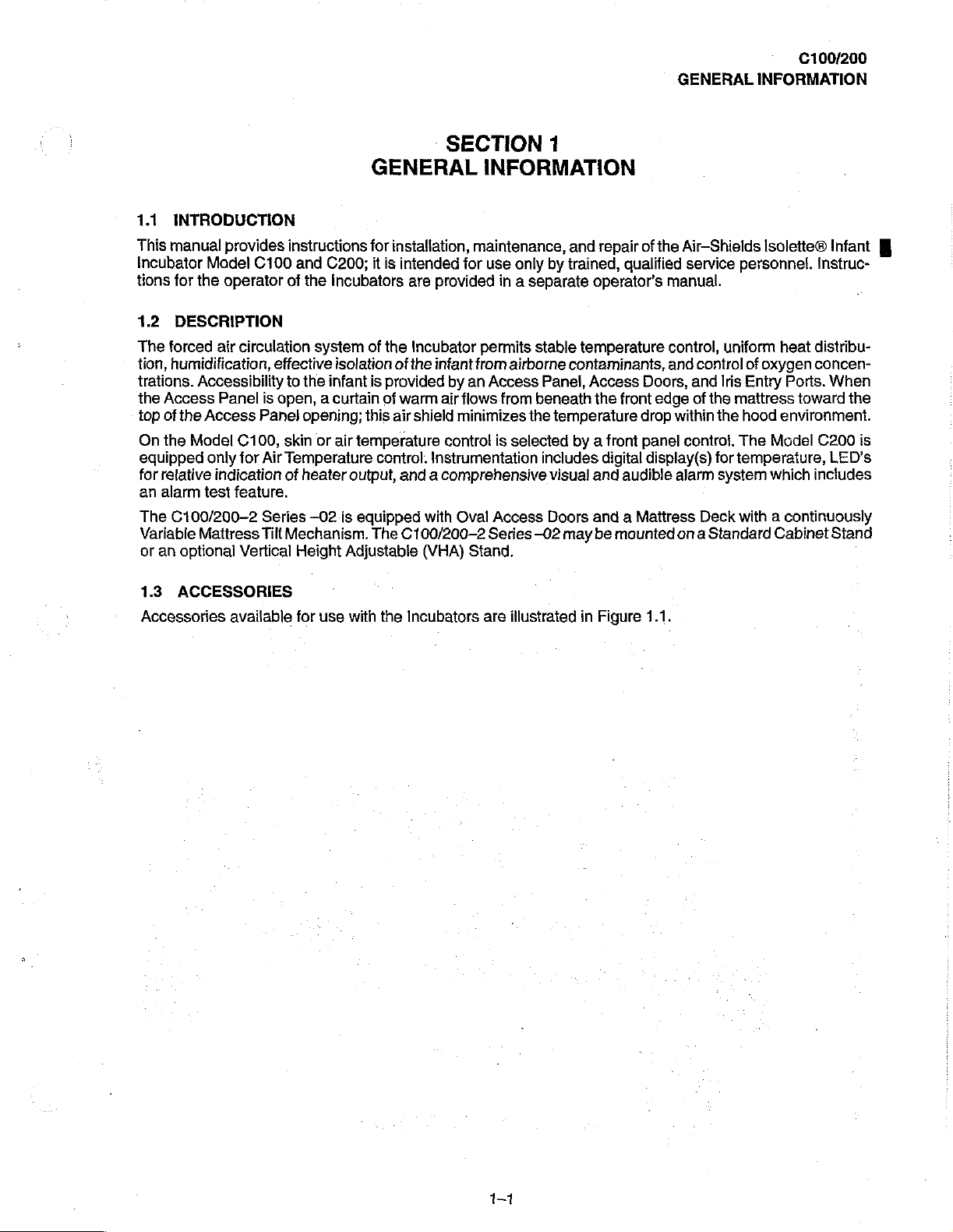
1.1
INTRODUCTION
This
manual
Incubator
tions
1.2
The
tion,
trations.
the
100
On
equipped
for
an
The
Variable
or
an
1.3
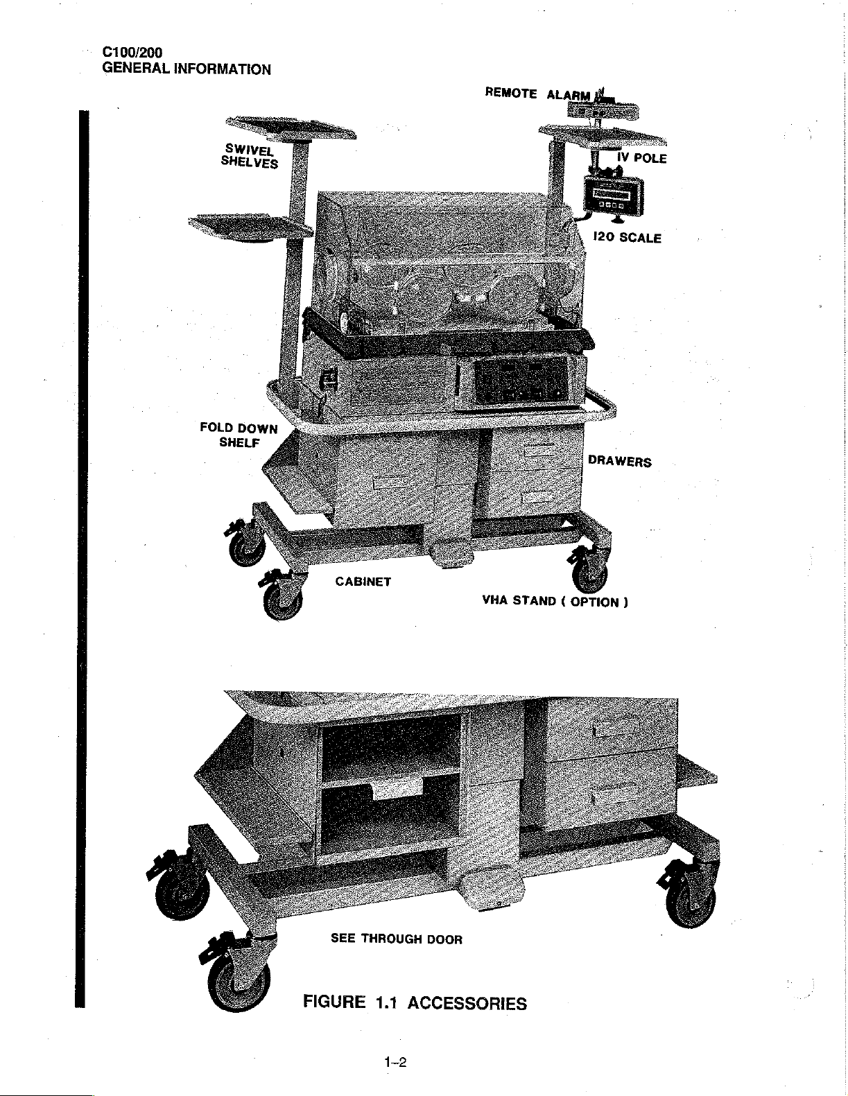
Accessories
Model
for
the
DESCRIPTION
forced
humidification,
Accessibility
Access
of
the
Access
the
Model
only
relative
alarm
test
C100/200-2
Mattress
optional
ACCESSORIES
provides
operator
air
circulation
Panel
C100,
for
indication
instructions
C100
of
effective
to
is
open, a curtain
Panel opening;
skin
Air
Temperature
of
feature.
Series
Tilt
Mechanism.
Vertical
available
and
C200;
the
Incubators
system
isolation
the
infant
or
air
heater
-02.is
Height
for
use
GENERAL
for
installation,
it
is
intended
are
of
the
Incubator
of
the
is
provided
of
warm
this
air
shield
temperature
control.
output,
Adjustable
with
and a comprehensive
equipped
The
C100/200-2
the
Incubators
SECTION
INFORMATION
maintenance,
for
use
only
provided
infant
by
air
contro!
instrumentation
with
(VHA)
in a separate
permits
from
airborne
an
Access
flows
from
minimizes
is
selected
Oval
Access
Series
Stand.
are
illustrated
1
and
by
trained,
stable
temperature
contaminants,
Panel,
beneath
the
temperature
by a front
includes
visual
Doors
-02
may
in
repair
of
the
Air-Shields
qualified
operator’s
Access
the
front
digital
and
audible
and a Mattress
be
mounted
Figure
service
manual.
control,
and
Doors,
edge
drop
within
panel
control.
display(s)
alarm
on a Standard
1.1.
uniform
control
and
Iris
of
the
the
for
system
Deck
mattress
Isolette©
personnel.
heat
of
oxygen
Eniry
hood
environment.
The
Model
temperature,
which
with a continuously
Cabinet Stand
[nstruc-
distribu-
concen-
Ports.
toward
C200
includes
Infant
When
the
is
LED’s
№
100/200
GENERAL
INFORMATION
FOLD
DOWN
SHELF
REMOTE
ALARM
120
iV
POLE
i
B
SCALE
CABINET
VHA
STAND
(
OPTION
)
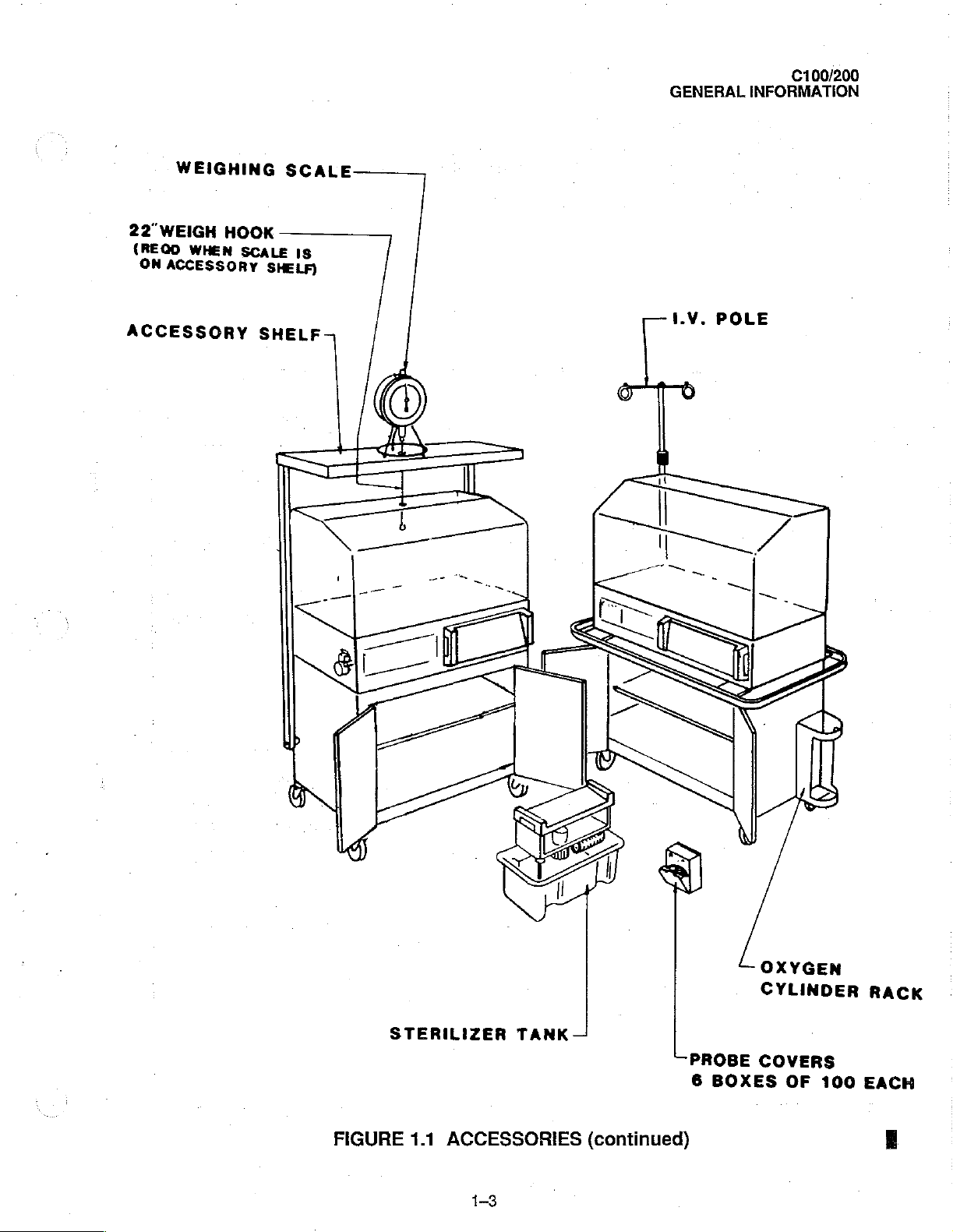
GENERAL.
C100/200
INFORMATION
WEIGHING
22"WEIGH
(REOD
ON
ACCESSORY
WHEN
ACCESSORY
HOOK
SCALE
SCALE
IS
SHELF)
SHELF
I.V.
POLE
FIGURE
4)
STERILIZER
1.1
ACCESSORIES
RET
DI
NES
TANK
5
(continued)
PROBE
6
BOXES
W
OXYGEN
CYLINDER
COVERS
OF
:
100
RACK
EACH
E
1-3
C100/200
GENERAL
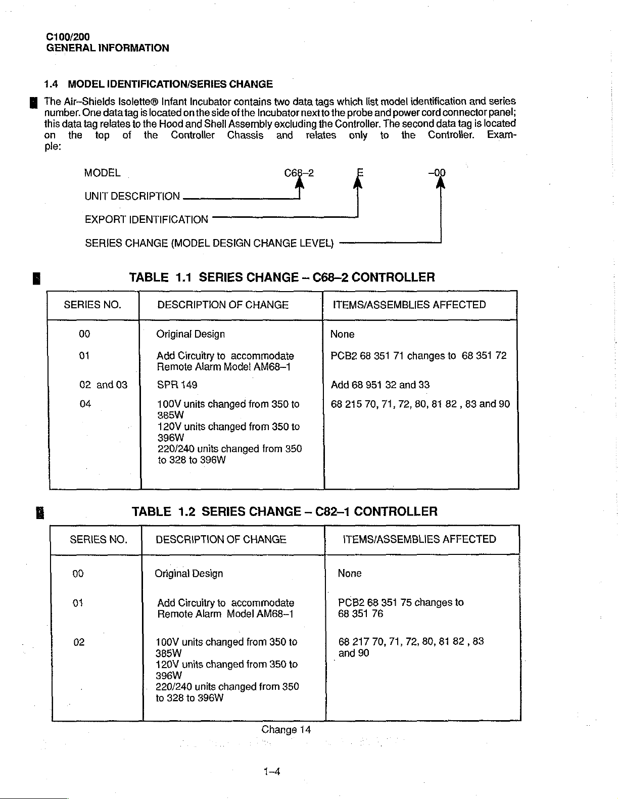
1.4
MODEL
The
Air-Shields
number.
this
data
on
the
ple:
INFORMATION
IDENTIFICATION/SERIES
Isolette®
One
data
tag
is
located
tag
relates
top
of
io
the
the
Hood
Infant
Incubator
on
the
and
Controller
side
Shell
CHANGE
contains
of
the
Incubator
Assembly
Chassis
two
data
tags
nextto
excluding
and
relates
which
the
probe
the
Controller.
only
list
model
and
to
identification
power
cord
The
second
the
and
connector
data
tag
is
Controller.
series
panel;
located
Exam-
MODEL
UNIT
EXPORT
SERIES
SERIES
00
01
02
04
DESCRIPTION
IDENTIFICATION
CHANGE
TABLE
NO.
and
03
(MODEL
1.1
DESCRIPTION
Original
Add
Circuitry
Remote
SPR
149
100V
385W
120V
396W
220/240
to
328
SERIES
Design
Alarm
units
units
units
to
396W
DESIGN
changed
changed
A
CHANGE
CHANGE - C68-2
OF
CHANGE
to
accommodate
Model
AM68-1
from
350
from
350
changed
from
LEVEL)
to
to
350
CONTROLLER
ITEMS/ASSEMBLIES
None
PCB2
68
351
71
changes
Add
88
951
32
and
68
215
70, 71, 72, 80,
—00
AFFECTED
33
81
82 , 83
to
68
351
and
72
90
TABLE
SERIES
00
01
02
NO.
1.2
SERIES
DESCRIPTION
Original
Add
Remote
100V
385W
120V
396W
220/240
to
Design
Circuitry
Alarm
units
units
units
328
to
396W
changed
changed
CHANGE
OF
CHANGE
to
accommodate
Model
from
from
changed
AM68-1
350
350
from
350
Change
1-4
to
to
-
C82-1
ITEMS/ASSEMBLIES
None
PCB2
68
68
and
-
14
CONTROLLER
68
351 75
351
76
217
70,
71, 72,
90
AFFECTED
changes
80,
81
to
82 , 83
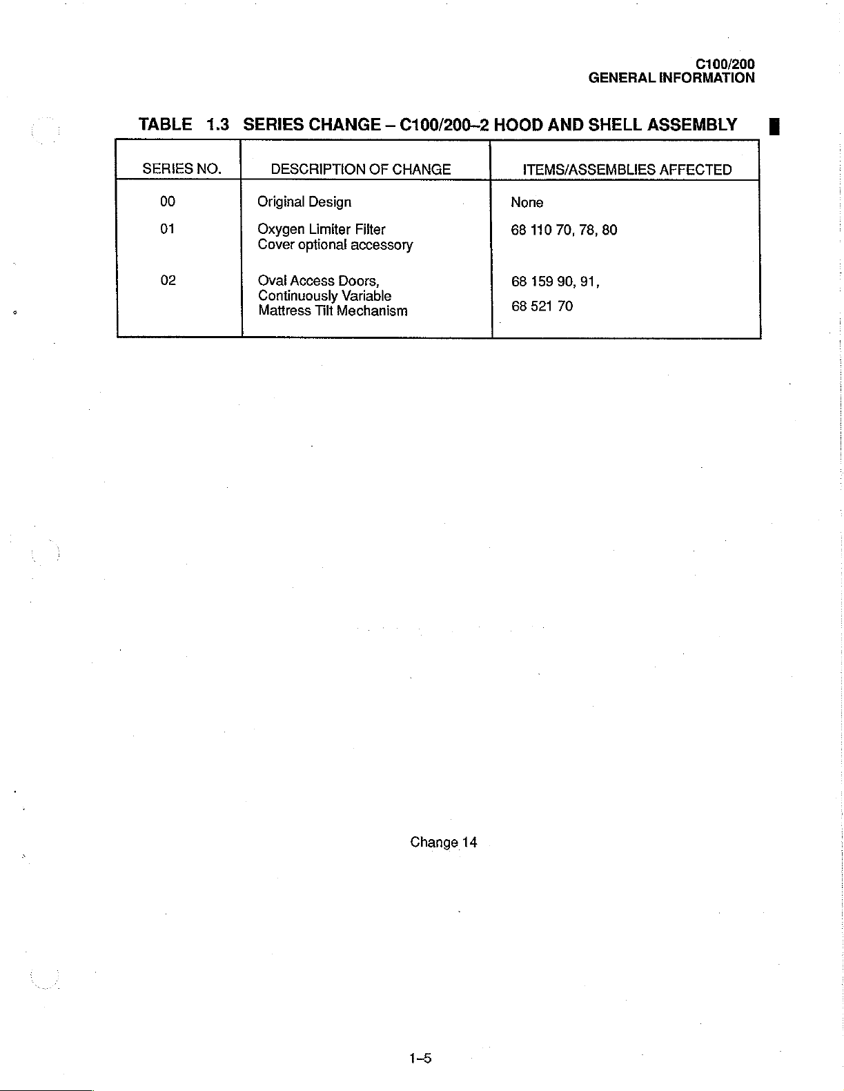
GENERAL
C100/200
INFORMATION
TABLE
SERIES
NO.
00
01
02
1.3
SERIES
DESCRIPTION
Original
Oxygen
Cover
Oval
Access
Continuously
Mattress
CHANGE
Design
Limiter
optional
Doors,
Variable
Tilt
Mechanism
—
C100/200--2
OF
CHANGE
Filter
accessory
HOOD
AND
ITEMS/ASSEMBLIES
None
68
110
70, 78,
68
159
90,
68
521
70
SHELL
80
91,
ASSEMBLY
AFFECTED
Change
14
 Loading...