

Air-Shields C100, C200 MAINTENANCE
PREVENTIVE
100/200
MAINTENANCE
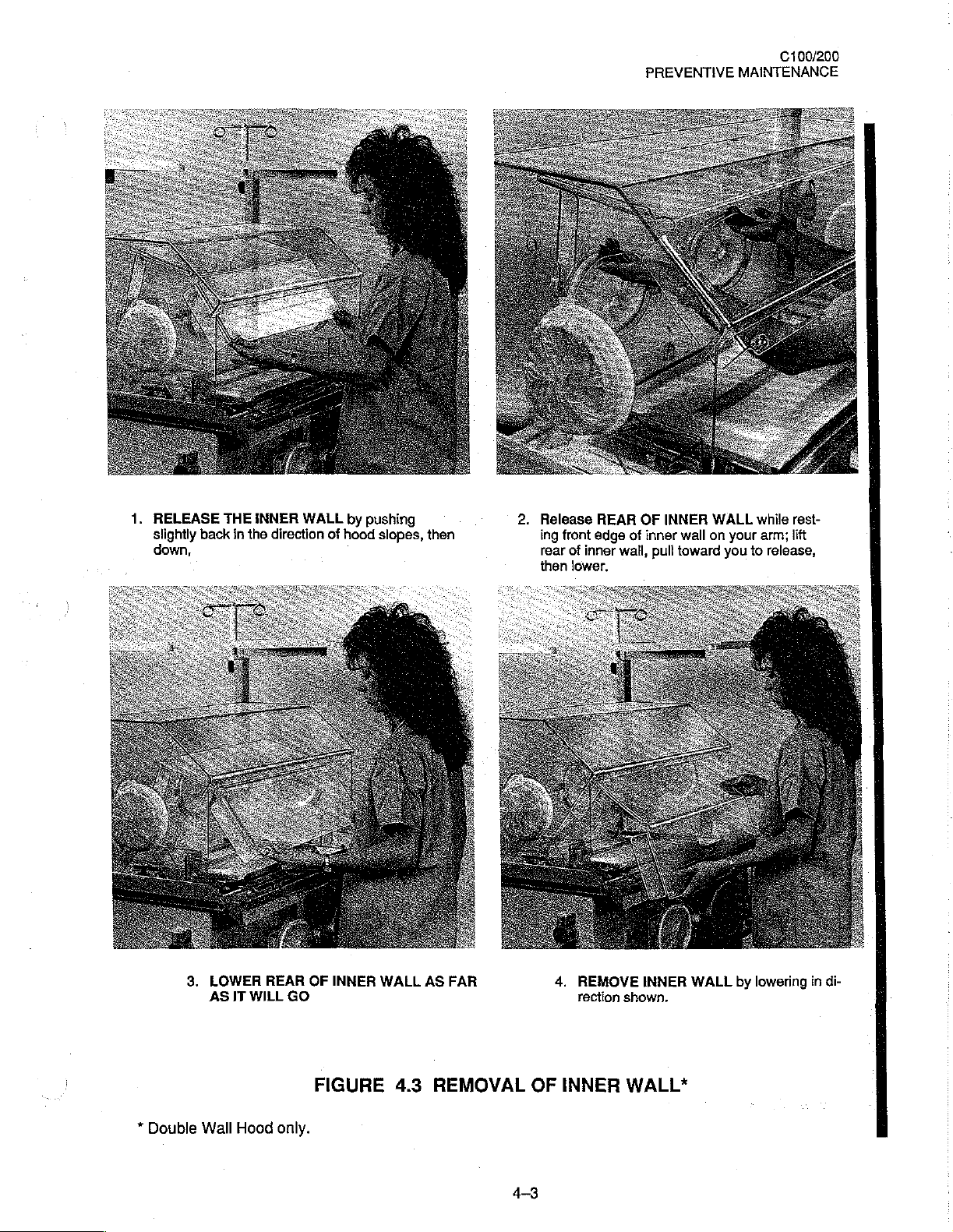
1.
RELEASE
slightly
down,
back
THE
in
INNER
the
direction
WALL
of
by
pushing
hood
slopes,
then
2.
Release
ing
rear
then
front
of
inner
lower.
REAR
edge
OF
of
inner
wall,
INNER
pull
WALL
wall
on
toward
your
you
while
arm;
to
release,
rest-
lift
*
Double
3.
LOWER
AS
Wall
IT
WILL
Hood
REAR
GO
only.
OF
INNER
FIGURE
WALL
4.3
AS
FAR
REMOVAL
OF
4-3
4.
REMOVE
rection
INNER
INNER
shown.
WALL*
WALL
by
lowering
in
di-
C100/200
PREVENTIVE
MAINTENANCE
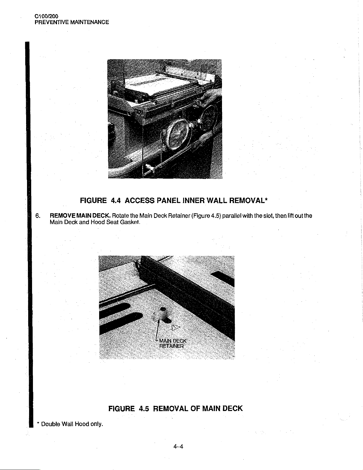
6.
REMOVE
Main
Deck
FIGURE
MAIN
DECK.
and
Hood
4.4
Rotate
Seat
ACCESS
the
Gasket.
Main
PANEL
Deck
INNER
Retainer
WALL
(Figure
4.5)
REMOVAL*
parallel
with
the
slot,
then
lift
out
the
*
Double
Wall
Hood
only.
FIGURE
4.5
REMOVAL
OF
MAIN
DECK
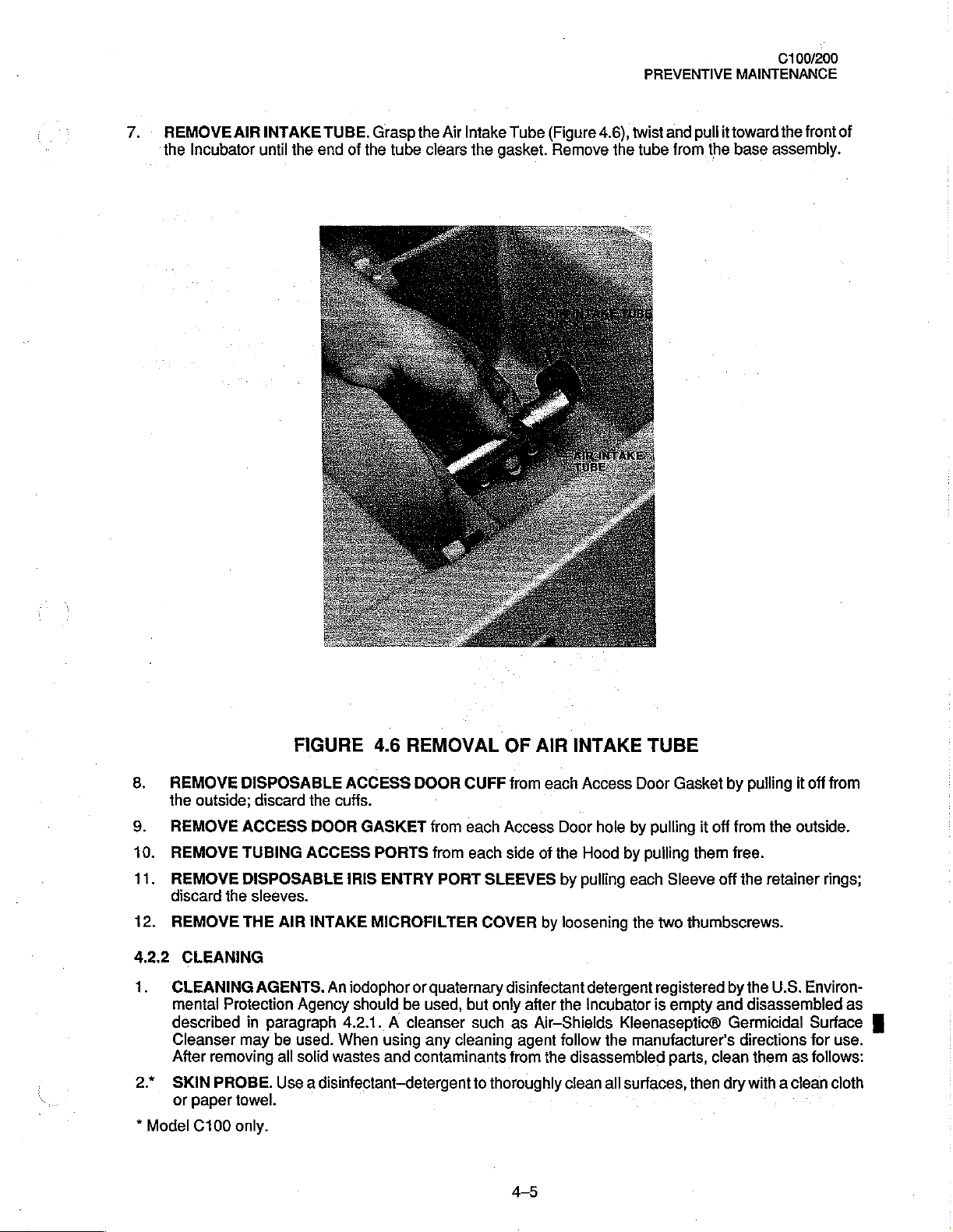
7.
REMOVEAIRINTAKE
the
Incubator
until
the
TUBE.
end
of
Grasp
the
tube
the
Air
clears
Intake
the
gasket.
Tube
(Figure
Remove
4.6),
twist
the
PREVENTIVE
and
pull
tube
from
MAINTENANCE
it
toward
the
base
C100/200
the
front
assembly.
of
8.
9.
10.
11.
12.
4.2.2
1.
2.*
*
Model
REMOVE
the
outside;
REMOVE
REMOVE
REMOVE
discard
REMOVE
CLEANING
mental
described
Cleanser
After
SKIN
or
the
CLEANING
Protection
removing
PROBE.
paper
C100
FIGURE
DISPOSABLE
discard
ACCESS
TUBING
DISPOSABLE
sleeves.
THE
AGENTS.
in
may
towel.
only.
the
DOOR
ACCESS
AIR
INTAKE
Agency
paragraph
be
used.
all
solid
Use a disinfectant—detergent
4.6
ACCESS
cuffs.
GASKET
PORTS
IRIS
ENTRY
MICROFILTER
An
iodophor
should
4.2.1. A cleanser
When
using
wastes
and
REMOVAL
DOOR
or
be
contaminants
CUFF
from
each
from
each
PORT
COVER
quaternary
used,
but
such
any
cleaning
to
OF
AIR
from
each
Access
side
of
SLEEVES
by
disinfectant
only
after
as
Air-Shields
agent
from
the
thoroughly
45
INTAKE
Access
Door
hole
by
the
Hood
by
by
pulling
loosening
the
follow
disassembled
clean
each
detergent
Incubator
Kleenaseptic®
the
all
surfaces,
TUBE
Door
Gasket
pulling
pulling
Sleeve
the
two
registered
is
empty
manufacturer's
parts,
by
it
off
from
them
free.
off
thumbscrews.
by
and
Germicidal
clean
then
dry
pulling
the
the
disassembled
directions
with a clean
the
retainer
U.S.
them
as
it
off
outside.
Environ-
Surface
for
follows:
from
rings;
as
use.
cloth
100/200
PREVENTIVE
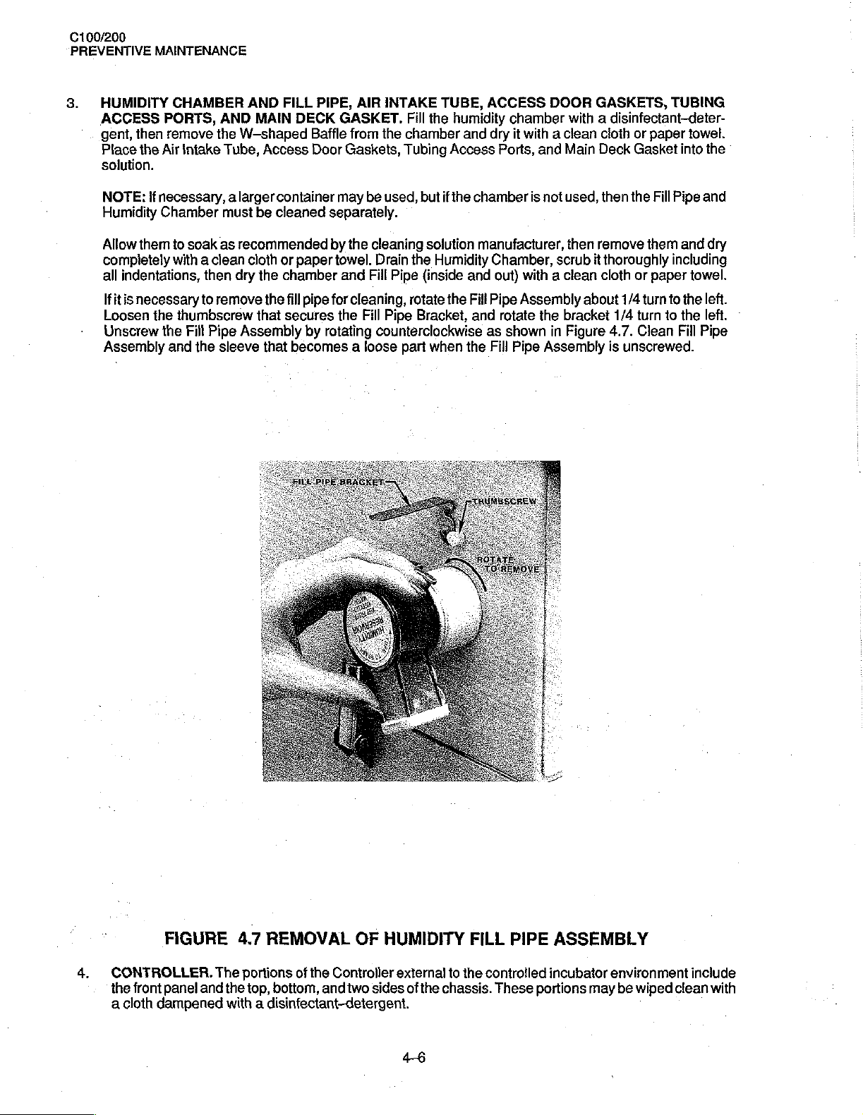
3.
HUMIDITY
ACCESS
gent,
Place
solution.
MAINTENANCE
CHAMBER
PORTS,
then
remove
the
Air
AND
the
Intake
AND
MAIN
W-shaped
Tube,
FILL
DECK
Access
PIPE,
AIR
GASKET.
Baffle
from
Door
Gaskets, Tubing
INTAKE
Fill
the
chamber
TUBE,
the
humidity
Access
and
ACCESS
chamber
dry
it
with a clean
Ports,
DOOR
and
GASKETS,
with a disinfectant-deter-
cloth
Main
Deck
TUBING
or
paper
Gasket
towel.
into
the
*
NOTE:
Humidity
Allow
completely
all
Ifit
Loosen
Unscrew
Assembly
if
necessary, a larger
Chamber
them
indentations,
is
necessary
the
the
and
must
to
soak
as
recommended
with a clean
then
dry the
to
remove
thumbscrew
Fill
Pipe
Assembly
the
sleeve
container
be
cleaned
cloth
the
that
that
may
be
separately.
by
the
cleaning
or
paper
towel.
chamber
fill
secures
becomes a loose
pipe
for
by
rotating
and
Fill
cleaning,
the
Fill
used,
but
if
the
chamber
solution
Drain
the
Humidity
Pipe
(inside
rotate
Pipe
Bracket,
counterclockwise
part
when
manufacturer,
and
the
Fill
and
the
is
Chamber,
out)
with a clean
Pipe
Assembly
rotate
as
shown
Fill
Pipe
not
used,
then
scrub
about
the
bracket
in
Figure
Assembly
then
the
remove
it
thoroughly
cloth
them
or
1/4
turn
1/4
turn
4.7.
Clean
is
unscrewed.
Fill
Pipe
and
including
paper
to
the
to
the
Fill
and
dry
towel.
left.
left.
Pipe
-
4.
CONTROLLER.
the
a
front
cloth
FIGURE
panel
and
dampened
4.7
REMOVAL
The
portions
the
top,
with a disinfectant-detergent.
of
the
bottom, and
OF
HUMIDITY
Controller
two
external
sides
46
of
to
the
chassis.
FILL
the
controlled
These
PIPE
portions
ASSEMBLY
incubator
environment
may
be
wiped
include
clean
with
PREVENTIVE
-
C100/200
MAINTENANCE
CAUTION:
mita
trical
CAUTION:
temperature
A.
B.
NOTE: A disinfecting
ofthe
gent,
5.
6.
Some
chemical
build-up
components.
The
face:
the
Remove
air
Clean
Controller.
then
MATTRESS
surfaces
MATTRESS
WASTES
tergent
nism. A cleanser
any
of
dust
portions
included
Controller
flow
allowing
cleaning
of
Failure
control
any
lint
sensor.
these
surfaces
The
thoroughly,
and
registered
are the
to
to
it
TRAY,
TILT
agent
cleaning
or
dirt
which
Do
not
spray
the
Controller
air
temperature
which
these
clean
could
and
cause
build-up,
tank
Controller
to
soak
pay
with a disinfectant-detergent,
is
available
rear
as
recommended
AIR
CURTAIN
then
dry
CONTROL,
contaminants
with
the
U.S.
such
as
Kleenaseptic®
follow
the
agents
may
cleaning
that
are
components
result
high
particular
as
surface
with a clean
may
be
conductive.
solutions
within
probe,
in
sufficient
oxygen
attention
an
accessory
is
COVER,
immersed
C100/200
from
the
Mattress
Environmental
Germicidal
manufacturer's
be
conductive
Do
not
onto
any
the
Incubator's
the fan
are
concentrations.
by
cloth
QT
impeller,
mounted.
lint
build-up
to
the
fan
then
from
Air-Shields
into
the
manufacturer
MAIN
DECK.
or a paper
(SERIES
Tilt
Control.
Protection
Surface
directions
impeller,
dry
the
—02)
Agency
for
and/or
permit
of
controlled
the
with a clean
tank
Use a disinfectant-detergent
towel.
An
Cleanser
use.
leave a residue
cleaning
these
surfaces.
environment
heater,
to
after
of
the
reduce
heater,
cloth
to
facilitate
filling
the
cleaning
gaskets,
air
air
it
INCUBATORS.
iodophor
or
should
may
quaternary
be
which
agents
cleaning
with a disinfectant-deter-
to
are
and
flow,
which
temperature
or
paper
solution.
REMOVE
disinfectant-de-
used
to
clean
also
be
used.
may
contact
on
the
the
surface
will
probe,
towel.
the
rear
to
ALL
the
When
per-
elec-
rear sur-
of
affect
and
surface
clean
all
SOLID
mecha-
using
WARNING:
in
an
7.
-
CAUTION:
Alcohol
Do
not
from
Hood.
8.
**
Model
DO
NOT
lubricate
enriched
HOOD
oughly,
baffles,
expose
these
AIR
than 3 months,
cover
WARNING:
build-up.
tions.
oxygen
AND
including
etc.,
then
can
cause
the
sources
INTAKE
with a disinfectant-detergent.
Be
C100
only.
environment.
CABINET
crazing
hood
can
MICROFILTER.
it
A
dirty
sure
(Optional
STAND.
the
inner
dry
with a clean
of
assembly
cause
should
Filter
the
filter
be
elevator
Use a disinfectant-detergent
wall
and
cloth
the
clear
to
cracking
Do
not
replaced.
may
affect
is
checked
in
C200).
tilt
mechanism
access
or
paper
acrylic
direct
of
attempt
Before
oxygen
.
with
door
heat
shield*.
towel.
Hood.
radiation
gaskets,
on a routine
Do
fading
to
clean
installing a new
concentration
oil
Clean
not
from
or
reverse
basis
or
other
to
clean
Make
sure
the
exposed
use
alcohol
germicidal
of
paint,
and
the
filter,
clean
and/or
commensurate
potentially
all
to
clean
surfaces
for
lamps.
crazing
microfilter.
cause carbon
flammable
surfaces
all
of
cleaning.
Ultraviolet
of
If
visibly
the
Microfilter
with
of
the
holes,
indentations,
the
cabinet
the
clear
dirty,
chamber
dioxide
local
material
hood
thor-
stand.
radiation
acrylic
or
older
and
condi-
4-7
100/200
PREVENTIVE
MAINTENANCE
4.2.3
IMPORTANT:
not
proper
After
REASSEMBLY
interchangeable
identification
cleaning
INSTALL
1.
ure
4.6.
INSERT
2.
INSTALL
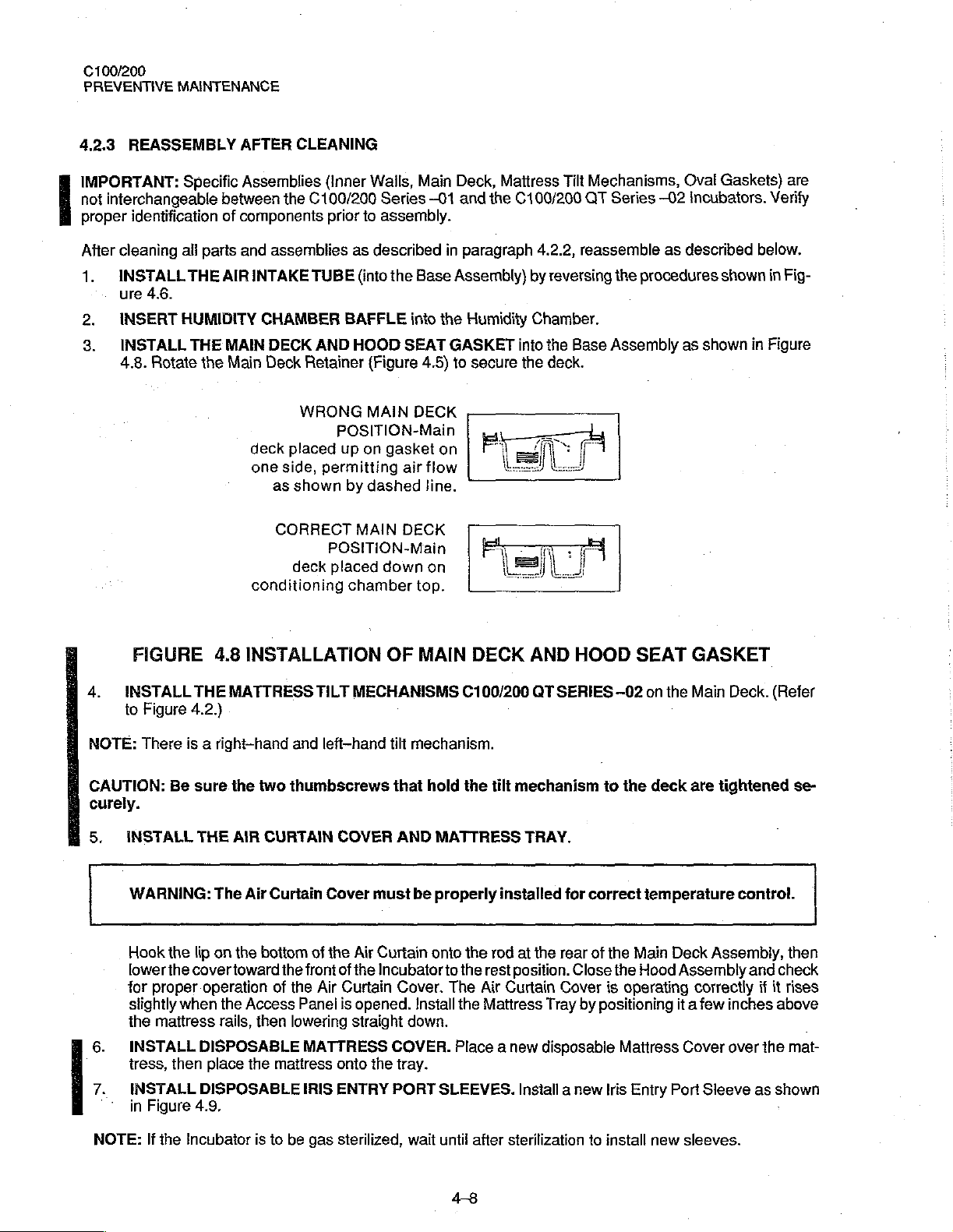
3.
4.8.
Rotate
Specific
between
of
all
parts
THE
AIR
HUMIDITY
THE
MAIN
the
Main
AFTER
Assemblies
components
and
CLEANING
the
C100/200
assemblies
INTAKE
CHAMBER
deck
one
conditioning
DECK
Deck
WRONG
placed
side,
as
shown
CORRECT
deck
TUBE
AND
Retainer
(inner
Wails,
Series
prior
to
assembly.
as
described
(into
the
BAFFLE
HOOD
POSITION-Main
up on
permitting
by
MAIN
POSITION-Main
placed
chamber
into
SEAT
{Figure
MAIN
gasket
air
dashed
DECK
down
Main
-01
Base
the
4.5)
DECK
on
flow
line.
on
top.
Deck,
Mattress
and
the
in
paragraph
Assembly)
Humidity
GASKET
to
secure
Tilt
C100/200
4.2.2,
by
reversing
Chamber.
into
the
the
deck.
Mechanisms,
QT
Series
reassemble
the
Base
Assembly
Oval
—02
Incubators.
as
described
procedures
as
shown
Gaskets)
Verify
below.
shown
in
in
Figure
are
Fig-
FIGURE
INSTALL
4.
to
NOTE:
CAUTION:
curely.
5.
There
INSTALL
WARNING:
Hook
lower
for
slightly
the
INSTALL
tress,
INSTALL
in
THE
Figure
4.2.)
is a right-hand
Be
sure
THE
the
lip
the
cover
proper
when
mattress
DISPOSABLE
then
DISPOSABLE
Figure
4.9,
4.8
INSTALLATION
MATTRESS
the
two
AIR
CURTAIN
The
Air
Curtain
on
the
bottom
toward
operation
the
rails,
place
of
Access
then
the
mattress
TILT
MECHANISMS
and
left-hand
thumbscrews
COVER
Cover
of
the
Air
the
front
of
the
the
Air
Curtain
Panel
is
opened.
lowering
MATTRESS
IRIS
straight
onto
ENTRY
OF
MAIN
tilt
mechanism.
that
hold
AND
must
be
Curtain
Incubator
Cover.
Install
down.
COVER.
the
tray.
PORT
DECK
C100/200
the
MATTRESS
properly
onto
the rod
to
the
rest
The
Air
the
Mattress
Place a new
SLEEVES.
AND
GT
tilt
mechanism
TRAY.
installed
at
the
position.
Curtain
Tray
disposable
Install a new
HOOD
SERİES
for
correct
rear
of
Close
Cover
by
positioning
SEAT
—02
on
to
the
temperature
the
Main
the
Hood
is
operating
Mattress
Iris
Entry
the
deck
Deck
Assembly
it a few
Port
GASKET
Main
Deck.
are
tightened
Assembly,
correctly
inches
Cover
over
Sleeve
(Refer
se-
control.
then
and
check
if it
rises
above
the
mat-
as
shown
NOTE:
If
the
Incubator
is
to
be
gas
sterilized,
wait
until
48
after
sterilization
to
install
new
sleeves.
PREVENTIVE
C100/200
MAINTENANCE
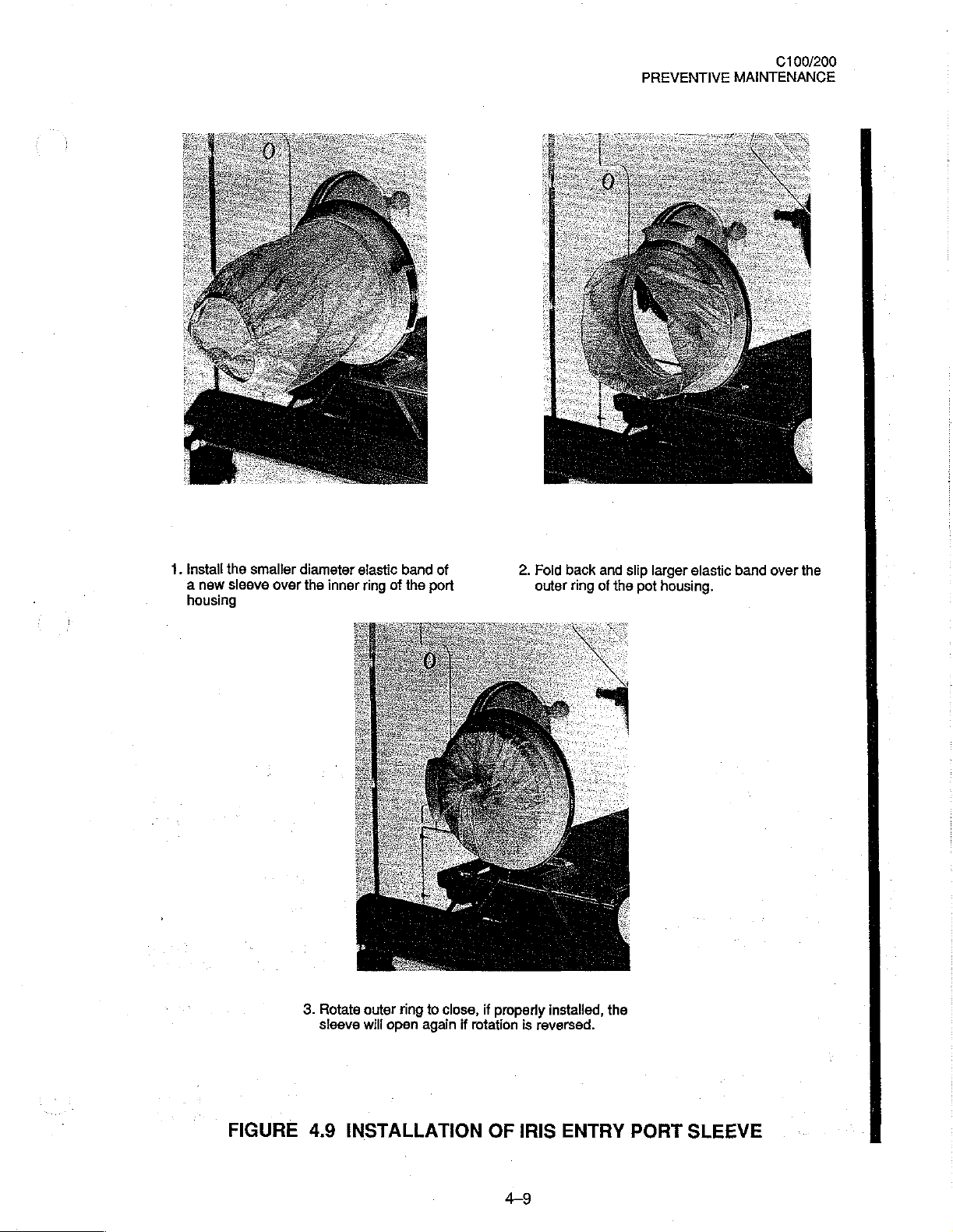
1.
Install
a
new
housing
the
smaller
sleeve
over
diameter
the
inner
3.
Rotate
sieeve
elastic
ring
of
outer
ring
will
open
band
the
again
of
port
to
close,
if
properly
if
rotation
2.
Fold
outer
installed,
is
reversed.
back
ring
and
of
the
slip
the
larger
pot
housing.
elastic
band
over
the
FIGURE
4.9
INSTALLATION
OF
IRIS
49
ENTRY
PORT
SLEEVE
C100/200
PREVENTIVE
8.
INSTALL A TUBING
or
torn.
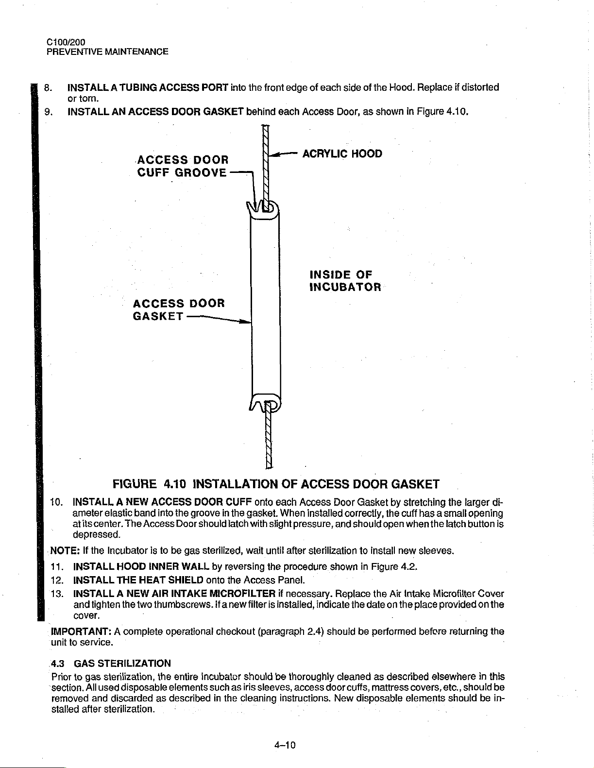
9.
INSTALL
MAINTENANCE
AN
ACCESS
ACCESS
DOOR
PORT
GASKET
into
behind
the
front
each
edge
Access
of
each
side
Door,
of
as
the
Hood.
shown
Replace
in
Figure
if
distorted
4.10.
ACCESS
CUFF
GROOVE
ACCESS
GASKET
DOOR
DOOR
——
„|
a
ACRYLIC
É
INSIDE
INCUBATOR
HOOD
OF
FIGURE
10.
INSTALL A NEW
ameter
atits
depressed.
NOTE:
11.
INSTALL
12.
INSTALL
13.
INSTALL A NEW
and
elastic
center.
If
the
tighten
Incubator
HOOD
THE
the
cover.
IMPORTANT: A complete
unit
to
service.
、4.3
GAS
STERILIZATION
Prior
to
gas
sterilization,
section.
removed
stalled
All
used
disposable
and
discarded
after
sterilization.
The
ACCESS
band
Access
is
INNER
HEAT
AIR
two
4.10
INSTALLATION
DOOR
into
the
groove
Door
should
to
be
gas
sterilized,
WALL
SHIELD
INTAKE
thumbscrews.
operational
the
entire
elements
as
described
onto
incubator
CUFF
onto
in
the
gasket,
latch
with
wait
by
reversing
the
Access
MICROFILTER
ifa
new
filter
checkout
such
in
the
(paragraph
should
as
iris
sleeves,
cleaning
OF
ACCESS
each
Access
When
installed
slight
pressure,
until
after
sterilization
the
procedure
Panel.
if
necessary.
is
instatled,
2.4)
be
thoroughly
access
instructions.
4-10
Door
correctly,
and
shown
Replace
indicate
:
should
cleaned
door
cuffs,
New
the
DOOR
Gasket
should
to
in
be
disposable
GASKET
by
the
open
install
Figure
the
Air
date
on
performed
as
described
mattress
stretching
cuff
has a small
when
the
new
sleeves.
4.2,
Intake
Microfilter
the
place
provided
before
elsewhere
covers,
elements
the
larger
opening
latch
button
returning
etc.,
shouldbe
should
di-
is
Cover
on
the
the
in
this
be
in-
・
PREVENTIVE
C100/200
MAINTENANCE
Release
Access
NOTE:
the
Doors
Gas
CAUTION:
Standard
Sterilizers
Upon
should
period
Gas
and
completion
be
properly
of
aeration
disposable
IMPORTANT:
turning
44
It
repairs
the
CALIBRATION
is
recommended
have
Controller
should
sterilization
Sterilization
latches
be
left
does
temperature
sterilization
Wilmot
Castle
of
gas
sterilization,
secured
at a temperature
dust
cover
should
A
complete
unit
to
service.
SCHEDULE
that
the
been
made.
and
slide
open.
The
not
eliminate
procedures
are
satisfactory
an
in
place
and
of
be
placed
operational
Controller
Calibration
and
the
unit
Air
Intake
the
should
as
programmed
aeration
the
C100
32
to
35
on
the
checkout
of
the
Incubator
test
out
about
Microfilter
need
for
not
exceed
by
as
these
do
period
of
Incubator
°C.
After
aeration,
Incubator.
procedure
be
procedures
1/4”.
The
may
routine
replacement
130 ° F
automatic
not
normally
16
to
24
should
(paragraph
tested
are
provided
Access
be
left
(54.5
equipment
exceed
hours
should
be
operated
if
the
unit
2.4)
and
calibrated
in
Panel
in
place.
of
the
°C).
such
130
be
allowed.
in a dry
is
not
to
should
at
Section 5 of
may
be
Air
Intake
as
made
°F
(64.5
condition
be
used
be
performed
least
annually
this
closed,
but
Microfilter.
by
American
°C).
The
Control
for
the
entire
immediately,
before
and
after
manual.
the
unit
a
re-
4-11

100/200
PREVENTIVE
MAINTENANCE
{This
page
is
intentionally
left
blank.)
4-12
C100/200
SERVICE
5.1
GENERAL
This
section
C100
and
IMPORTANT:
ably
in
this
5.2
CALIBRATION
5.2.1
This
paragraph
Unless
1.
The
2.
The
3.
Primary
GENERAL
otherwise
provides
C200
Incubators.
It
should
manual.
WARNING:
frame
provides
indicated,
Gontroller
Controller
is
is
power
calibration,
be
noted
PROCEDURES
The Motor
may
be
at
calibration
all
calibration
removed
connected
applied
to
from
the
SECTION
SERVICE
troubleshooting,
that
the
terms
Assembly
mains
potential.
procedures
procedures
the
Incubator
to a primary
Controller
and
"SET
is
for
source
for a minimum
5
removal
TEMP”
not
grounded.
the
Controllers and
are
performed
and
the
cover
of
the
correct
of
and
replacement
and
“SET
Under
under
is
removed.
voltage and
ten
minutes
POINT"
fault
tests
the
before
instructions
are
conditions,
for
the
Incubator.
following
frequency.
calibrating.
for
the
used
interchange-
the
metal
conditions:
Model
5.2.2
The
test
tion
tests.
.
ㆍ
ο
.
ㆍ
.
.
TEST
EQUIPMENT
equipment
Equivalent
Probe
Simulator,
Logic
Probe — capable
Variable
Digital
Oxygen
Flowmeter,
Leakage
Transformer,
VOM,
Analyzer,
Current
REQUIRED
listed
below
test
equipment
Part
No.
of
General
Fluke
Model
Ametek,
Victor — Model
Tester,
Bio—Tek
is
required
may
68
900
+/—
12
Vdc
Radio
8060A
Thermox
1099-0025
for
calibration
be
substituted.
80
Model
Instrument
501
of
WSM
Division,
(Change
the
Controller
T3AW
16)
Model
and
performing
S-3A1,
Oxygen
Pittsburgh,
PA.
Concentra-
5-1
100/200
SERVICE
5.23
TEST
Connect
1.
Controller.
+/—
2.
Onthe
to
3.
On
location
PCB2—
SETUP
2V~
AIR.
the
PROCEDURE
1.
Refer
2.
Adjust
3.
Onthe
SKIN.
4.
Adjust
5.
Turn
Monitor
6.
Turn
Models);
6a.
On
the
MODEL
the
Simulator
Connect
(110/120V
Controller,
Simulator,
of
test
points
to
Figure
R35
Simulator,
Connect
R50
off
the
TP15
the
simulator,
5.1
on
PCB2
the
for a reading
POWER
with
unit
on.
80
+/-
C100
to
the
the
ac
line
Models);
set the
2V- (100V
set
AIR
set the
set
Set
MODE
and
adjustments.
and
connect
for a reading
the
MODE
DVM
between
of
switch
the
logic
the
variac
the
mode
PATIENT
cord
through a variac
240
+/-
and
SKIN
switch
the
of
switch
TP13
-350
+/-
on
the
Controller.
probe.
as
follows:
Models).
switch
PROBE
2V~
set
DVM
-350
to
50
On
to
to
(+)
mV
AIR.
and
(220/240V
Temp.
between
SKIN
PCB2,
AIR
+/-
and
on
95
switches
and
50
on
TP22.
the
Connect
+/-
turn
AUXILIARY
and
turn
Models);
to
the
TEMP
TP20
(+)
mV
on
the
the
Controller,
DVM.
the
2V~
(110/120V
R100
fully
PROBE
jacks
on
the
unit.
Set
100
+/-
2V-
36.0
°C.
Setthe
switch
and
DVM.
logic
to
36
TP22
on
set
the
CONTROL
probe
between
Models);
counterclockwise.
on
the
the
variac
(100V
CONTROL
°C.
Refer
PCB2.
+12
190
Side
as
follows:
Models).
MODE
to
Figure
MODE
Vdc
+/-
2V~
Panel
of
switch
5.1 for
Switch
and
ground.
(220/240V
the
120
to
7.
On
the
7a.
Set
Vac (100V
Set
(100V
approximately
Turn
the
Controller,
logic
probe
the
variac
Models).
the
variac
Models).
off
the
set
just
as
follows:
as
follows:
The
two
Power.
the
AIR
stays
off
130
The
light
120
fight
should
seconds
Remove
SET
TEMP
constantly
+/-2
Vac
on
the
logic
+/~2V~
(Heater
the
(110/41
go
off
Off).
logic
probe.
Switch
(full
heater
(110/120V
probe
should
20V
Models);
for
approximately
to
37
°C.
power).
Models);
be on
Slowly
240
four
turn
260+/- 2 Vac
for
approximately
+/-
2V~
seconds
R100
clockwise
(220/240V
50
(220/240V
(Heater
until
Models);
percent
Models);
On)
and
the
108+/—2
of
the
100
come
light
on
time.
+/-2V-
on
for
5-2

=
日
>
o
=
Eni
ba
a]
P
sé
ae
B
Oto
EC
PS
Bdl
P
EL
0
S
Lo
=>
г
20040
や
STI
a
DPédl
E
v
一
ARE
eg
a
和
=)
SEV
Q
mo
o
Sat
의
8
O
gidin
+
эп
sn
<
O
3
5
5
5
그
CC
mee
om
tetta
п)
suy
a
an
06012
ee!
a
120,
5
¢
be
buy
069
ný
MBE
seu
o
iz
Pê
21
mm
ČI
úd
poi
Ve.
©
GF
E
cu
Pau
7
58
O
DO
o
O
8001
3
$
Gigi
B
E
EİN,
S
e
è
zou
o
E
o
0
*
=
"L
nana)
|
6
čl
o
mi
2
EE.
Ler
°С
$
em
gın
Zin
Doro
-C
EA
O
ιο
ОНИ
sora
0
9bdl
L
o
00
58
SE
gö
ANY
SLNIOd
LS31
osu
JO
|
|
NOLLY901
SIN
ヨ
WLSPQV
‘(0019
SALYA
o
LABS
+
S
oy
10018
μμ
©
го
©
μη
ozdi
are
orali
8
Ze
aziona
à
s
ita
or
M.R.
O
ade
1300W)
6800
WS
+
a
——
“44
15€
89
зая
ON
ASSY
da
|
ヨ
HnOH
10
o
|
seu
C100/200
SERVICE
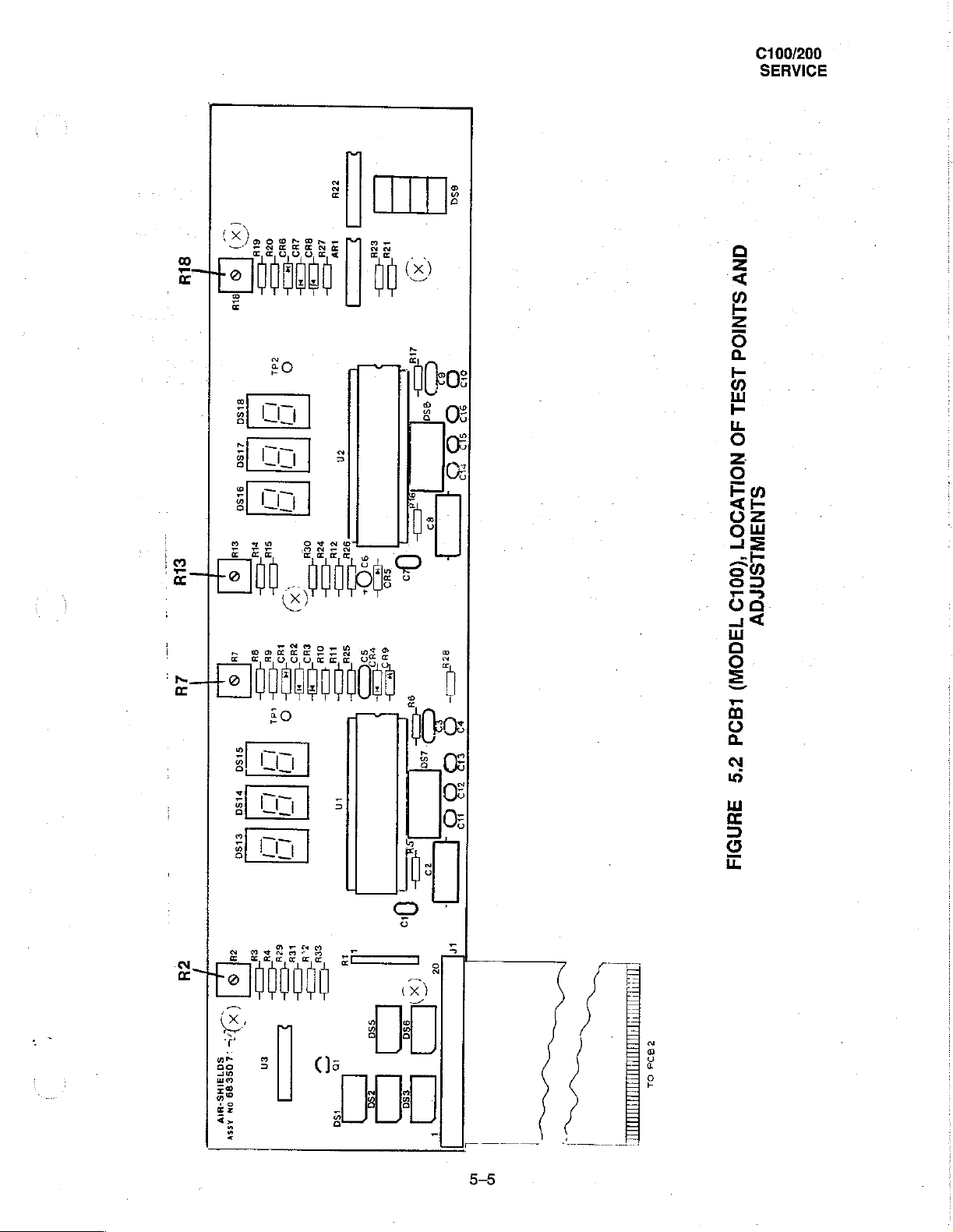
5.2.4
PCB1 - MODEL
TEST
SETUP
Remove
1.
Panel.
POWER
2.
Gonnect
the
Simulator
test
points
PROCEDURE
On
PCBI,
2.
Set
the
3.
Repeat
4.
Set
the
5.
On
PCB1
6.
Set
the
Repeat
7.
C100
ihe
CONTROL
Set
PCB1
and
switches.
the
Simulator
to
36°C.
and
adjustments.
adjust
R7
until
Simulator
steps 1 and 2 to
Simulator
adjust
Simulator
to
to
R18
to
20
AIR
20
steps 5 and 6 to
MODE
PCB2
to
the
Set
the
the
°C.
ensure
mode
until
°C.
ensure
knob.
vertically
PATIENT
Controller
left
display
Adjust R2
proper
and
the
right
On
PCB1
proper
Remove
behind
PROBE
and
(SKIN)
on
PCB!
settings.
36.0
°C.
display
adjust
settings.
the
five
the
brackets
and
AUXILIARY
Simulator
reads
until
the
Readjust
(AIR)
reads
R13
until
Readjust
screws
to
SKIN
36.0
left
if
36
+/-
the
right
if
which
hold
located
behind
PROBE
mode.
Refer
+/-
0.1
°C.
display
necessary.
0.1
(SKIN)
°C.
display
necessary.
PCB1
the
jacks
to
reads
(AIR)
and
PCB2
to
SILENCE/RESET
on
the
Side
Figure
5.2.
for
20.0
+/-
reads
20+/-
the
Front
Panel.
location
0.1
°C.
0,1
°C.
and
Set
of
5.2.5
TEST
1.
PCB2-
SETUP
Connect
ac
fine
cord
els);
240
On
the
Controller,
On
the
Simulator,
location
MODEL
the
C200
Simulator
through a variac
+/-2V~
(220/240V
set
set
of
test
points
to
the
AUXILIARY
and
Models);
the
SET
the
MODE
and
adjustments.
turn
TEMP
switch
on
the
100
°C
to
PROBE
unit.
+/-
switch
AIR and
jack
on
the
Set
the
variac
2V~ (100V
to
36.0
°C.
the
TEMP
Side
Panel
as
follows:
Models).
switch
to
of
120
36
the
+/-2V~
°C.
Controller.
Connect
(110/120V
Refer
to
Figure
Mod-
5.3
the
for
5-4
ㄷㄷ
teu
100/200
SERVICE
ssa
Luv
sn
|
o
>
pa
ES
X)
PE
üm
o,
TE
45H
Do
5
ο
asd
686s
95
+
oo
913
S
PD
QNV
SINIOd
1S
ヨ
I
O
NOILVOO1
__
SLNAWLSNrav
(0019
(x)
eus
P
sug
oa
вв
>=
©
few
8150
215а
9150
t+
zs
OHIO]
|
I
1
Et
+
O
{ORTI
pa
기
]
1
一
et
ou.
X
var
+
cul
sw
„=
|
I
二
©
i
TICON)
¿us
eua
me
ou
oo
=
一
-
In
3
>
ow
==
Oo
~
Es
O
v
159)
6067
Eh
2
во
75
3)
lgod
z9
UNO
24
wl
©
Sisa
visa
esa
eu
sa
ot
E
O
[ENO
一
一
一
cu
7
a
ui
L
©
j
(X)
~~"
©
:109689
en
5013IHS-U1Y
on
assv
vi
>
ev
vei
£
그
E
нЕ
se
ni
ーー
za
CT
‘sa
.
55а
>
050
S)
(x
τες
[7]
a
Mo
DZ
0000
上
5-5
100/200
SERVICE
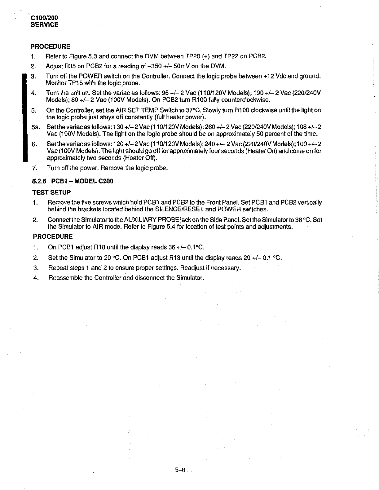
PROCEDURE
1.
Refer
2.
Adjust
3.
Turn
Monitor
4.
Turnthe
Models);
5.
Onthe
the
5a.
Setthe
Vac
6.
Setthevariacas
Vac
approximately
7.
Turn
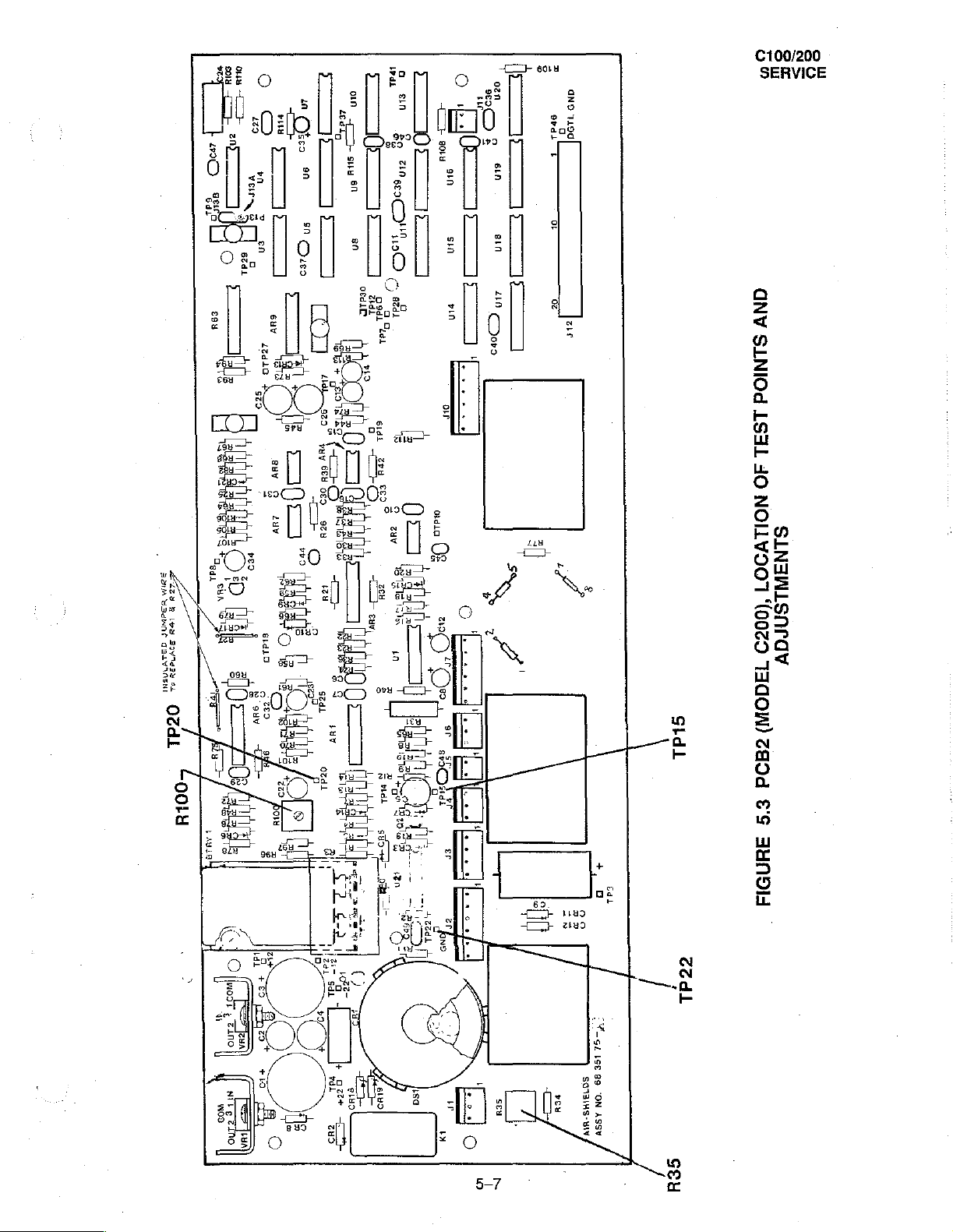
5.2.6
TEST
1.
2.
PCB1—
SETUP
Remove
behind
Connect
the
PROCEDURE
to
Figure
R35
off
the
TP15
Controller,
logic
variac
(100V Models).
(100V
off
the
Simulator
on
POWER
with
unit
on,
80
+/— 2 Vac
probe
as
Models).
the
power.
MODEL
the
five
brackets
the
Simulator
to
5.3
PCB2
Set
set
just
follows:
follows:
two
screws
AIR
and
connect
for a
reading
switch
the logic
the
variac
(100V
the
AIR
stays
off
130
The
light
120
The
light
seconds
Remove
C200
which
located
to
the
mode.
the
DVM
of
—350
on
the
Controller.
probe.
as
follows:
Models).
SET
TEMP
constantly
+/—2
Vae
on
the
logic
+/-2
Vac
should
(Heater
the
behind
AUXILIARY
Refer
logic
høld
to
go
Off).
PCB1
the
Figure
.
between
+/—
50mV
Connect
95
+/— 2 Vac
On
PCB2
turn
Switch
(full
(110/120V
(110/120V
off for
probe.
SILENCE/RESET
PROBE
to
heater
Models);
probe
should
Models);
approximately
and
PCB2
jack
5.4
for
TP20
(+)
on
the
the
logic
(110/120V
R100
37°C.
Slowly
power).
260
be on
240
to
the
Front
and
on
the
location
and
TP22
on
DVM.
probe
between
Models);
fully
counterclockwise.
turn
R100
+/- 2 Vac
approximately
+/- 2 Vac
four
seconds
Panel.
POWER
Side
Panel.
of
test
(220/240V
(220/240V
Set
switches.
Set
points
(Heater
and
PCB2.
+12
Vde
190
+/— 2 Vac
clockwise
Models);
50
percent
Models);
On)
PCB1
and
the
Simulator
adjustments.
and
uniil
the
of
and
come
PCB2
to
ground.
(220/240V
light
on
108
+/—
2
the
time.
100
+/-
2
on
for
vertically
36
°C.
Set
1.
2.
3.
4
On
PCB1
adjust
Set
the
Simulator
Repeat
Reassemble
steps 1 and 2 to
R18
to
the
Controller
until
20
*C.
the
display
On
ensure
and
reads
PCB1
adjust
proper
disconnect
settings.
36
+/-0.1°C.
R13
until
Readjust
the
Simulator.
the
display
if
reads
necessary.
20
+/-
0.1
°C.
on
en
mo
TT
Teo
Sy
Gum
BoA
WSdWOP
TLV
INSNE
Tadı
Zu
в
bpm
Bovnešy
où
OZd
上
al
NEZ
OT
€
T
Looru
ou
ALI
6001
202
Vera
i
o
©
=
129469
sido
E
+
|
=
e
=
Sad
iş
©
di
a
on
te
Fo
o
su
sn
en
ein
58
o
zın
sd
sn
io
の
addi
cs
FER
sidi
よら
E
Es
3
E
E
더
JA:
u,
к
ne
ψ
sino
ее
m
ar
5
る
이은
er
i
sou
an
sin
pin
or
calo
-
o
ες)
ir
so
SP
893
SO
+
o
ozn
SED
εις
EO
£
sin sin
TET:
210
(Doro
=
ОНИ
В
и
sou
96801
α
+
마
σσ
EN
I
aN9
1190
ze
,
\
C100/200
SERVICE
QNV
SINIOd
1S
ヨ
1
ヨ
O
NOLVOOT
SLNAWLSNraVv
(0029
TAdOW)
Sidi
240d
£'S
нот:
AHNOI
5-7
pe
—
34
156
89
S0331HS-
ON
ASSV
819
AZ IN
seu
C100/200
SERVICE
esa
giù
ELY
1
eeu
=
©
CINV
©
pedali
3
6H
一
8
+
ad
一
ll
st
SINIOd
a
SIGG
isa
AA!
1159
SST
>
ul
=
mu
O
US)
P
στὴ
oy
so
4
=
三
三
20800000
a
TE
06
6
|
==
SS
65
©
LS3L
40
NOILV907
ANTIALSAPAY
(0029
TAGOW)
a
=
О
DI
полон
=
S0731HS-HIv
ss
sey
一
©
西西
а
290
ir
o
Eo)
LAL)
SET
EST
T
|
LEOd
#°9
anel
=
|
5-8
C100/200
SERVICE
5.2.7
TEST
1.
2.
LEAKAGE
SETUP
Connect
is
ungrounded,
The
leakage
tance
of
must
be
PROCEDURE
1.
Use
the
ground
micro-amps
2.
Reverse
3.
Perform
5.2.8
TEST
2.
OXYGEN
SETUP
1.
Place a calibrated
Apply
PROCEDURE
1.
Turn
the
2.
After
40
3.
Increase
centration
CURRENT
the
Controller
Turn
current
1000
ohms.
adjusted
Leakage
such
as
in
the
plug
steps 1 and 2 with
to
the
test
If
the
to
provide
Current
the
ground
120
Vac
and repeat
CONCENTRATION
oxygen
oxygen
at a flow
unit
ON.
minutes
the
Oxygen
level
is
of
operation,
flow
between
TESTS
the
primary
POWER
standards
Leakage
it.
Tester
connection
Units
or
step
the
Controller
analyzer
rate
of 8 LPM
verify
to
12
LPM.
65%
power
switch
provided
Tester
to
measure
500
micro-amps
1.
TESTS
on
to
that
After
and
95%.
source
on.
in
the
being
between
of a wall
POWER
.
the
maitress
the
O2
the
oxygen
another
through
procedure
used
receptacle.
in
nipple
40
an
does
not
the
chassis
The
220/240
switch
OFF.
in
the
Incubator.
on
the
concentration
minutes
ungrounded
below
assume
provide
Vac
Filter
of
this
of
the
leakage
Units.
Cover.
level
operation,
adapter
unit
current
is
plug,
leakage
resistance,
under
must
between
verify
that
so that
the
unit
through a resis-
the
test
set-up
test
and a known
not
37%
the
exceed
and
oxygen
100
52%.
con-
|
5-9
C100/200
SERVICE
5.3
TROUBLESHOOTING
WARNING:
frame
5.3.1
Troubleshooting
form
good
5.3.2
The
equipment
GENERAL
guides
of
flowcharts.
condition.
TEST
EQUIPMENT
test
equipment
may
be
e
Digital
.
‧
+
« © Variable
9
e
Voltmeter,
Logic
Probe — capable
Oscilloscope,Tektronix
Probe
Simulator,
Transformer,
Resistor,
Resistor,
3.6
4.3
The
may
be
at
for
the
lt
is
assumed
REQUIRED
listed
below
substituted.
Fluke
Model
of
Model
Part
No.
General
K,
1/4
Wat,
K,
1/4
Watt,
Motor
Assembly
mains
Incubators
that
is
|
12
68
5%
5%
poteniial.
an
attempt
required
8060A
Vdc
465
900
80
Radio
is
not
and
the
Controllers
has
been
for
troubleshooting
Model
WSM
grounded.
are
made
to
the
Coniroller
T3AW
Under
fault
presented
calibrate
the
conditions,
under
unit
and
of
the
Incubator.
the
paragraph
that
all
Equivalent
metal
5.3.3
cables
in
the
are
test
in
9
Resistor,
ㆍ
Resistor,
9
Oxygen
5.3.3
ап ac
TROUBLESHOOTING
Unless
procedures
Controller
otherwise
power
400
100
Analyzer
specified
source
described
is in
the
Ohms,
Ohms,
Incubator.
1/4
1/4
Flowmeter
on
and
the
in
paragraph
the
POWER
Watt,
5%
Watt,
5%
PROCEDURES
troubleshooting
switch
5.2
have
is
on.
been
charts,
all
checks
The
troubleshooting
attempted.
Flowcharts
are
made
charts
with
5-14
the
Controller
assume
and
5-15
that
assume
plugged
the
calibration
that
into
the
5-10
 Loading...