

Air-Shields 7810, 7820, 7830, 7840 User manual
infant
infant
Wall
Free
Wall
From
Intensive
Iniensive
Mounted
Standing
Mounted
Hill-Rom
Care
Care
Infant
Infant
Infant
Air-Shields
Sysiem
System
Intensive
Warmer
Warmer
for
ihe
Care
Delivery
System
Room
Product:
For
Paris
USA
intemational:
Or
(800)
445-3720
Technical
Canada
Contact
Systems
Assistance
(800)
your
distributor.
7810/7820/7830/7840
man212
267-2337

LIMITED
The
product
from
During
labor
This
This
or
consequential
*The
comply
service
being
Hill-Rom
All
Calibrations
charge
warranty
1.
2.
4.
warranty
Accreditation
Air-Shields,
consumable
the
warranty
for
is
Damage
The
customer
The
customer
inc.
Sale
or
is in
with
this
can
be
performed
are
replacing
rendered
damages
standard,
described
and
disposable
considered
period
any
the
void
to
the
unit
fails
uses
service
is
lieu
of
all
Manual
for
we
by
in
this
manual
Inc.,
Hatboro,
normal
defective
parts
within
and
Hil-Rom
is
incurred
to
maintain
any
parts,
performed
other
warranties,
including
Hospitals
recommend
certified
WARRANTY
is
warranted
with
the
following
products
loss
are
guaranteed
maintenance
parts other
the
as a result
the
accessories,
by a non-certified
of
requires
that
technicians
than
continental
Air-Shields,
of
unit
in a proper
expressed
use,
propery
each
piece
you
participate
through
against
defects
exceptions:
to
be
and
are
not
those
listed
U.S.
Inc.
cannot
mishandling.
manner.
or
fittings
not
service/dealer
or
implied,
and
damage,
of
equipment
in
our
our
Product
in
materials
free
from
included
above
will
be
held
specified
agency.
Hill-Rom
or
personal
to
be
Preventive
Service
or
workmanship
defects
in
the 1 year
be
replaced
tiable
for
or
sold
Air-Shields,
injury
tested
prior
Maintenance
Group
upon
shipment
warranty.*
at
no
conditions
by
Hill-Rom
Inc.
resulting
to
initial
and
authorized
for
one
only.
charge
resultant
Air-Shields,
shall
from
breach
use
and
Program
dealers.
year
to
the
in
no
atieast
during
from
the
customer.
therefrom
event
be
liable
of
warranty.
annually
the
warranty
date
of
shipment
There
will
if:
for
incidental
thereafter.
period.
be no
To
This
For
optimal
located
throughout
da
(800)
tor for
service,
Cat.
A123456789
E123456789
SERVICE
performance,
267-2337.
product
the
United
Customers
service
States
outside
and
should
Canada
the
U.S,
be
performed
and
are
and
Canada
only
dispatched
should
Hill-Rom
A
HILLENBRAND
330
Jacksonville
991
78
No.
25-14
INDUSTRY
Road,
Hatboro,
by
qualified
for
contact
Air
PA
service
required
their local
19040
personnel.
maintenance
factory-authorized
Shields.
.
Technical
by
calling
Printed
in
rinted
Change
Change
Change
Change
Change
Change
Change
Change
Change
Change
Change
Change
Change
Services
USA
(800)
Hih-Rom
U.S.A.,
in
01
02
03
04
05
06
07
08
09
10
11
12
13
representatives
445-3720
Air-Shields'
184
2,
U.S
11/84
3/86
9/86
4/87
1/88
4/92
12/92
9/93
3/94
1/95
11/85
2/97
12/98
and
Cana-
distribu-
are

PLEASE
READ
Please
Since
and
incorporated
separate
package.
to
THIS
MODIFICATIONS
TO
CANNOT
OPERATION
OR
check
Hill-Rom
component
into
sheets
Changed
the
changed
MANUAL
MAINTAIN
ASSUME
OF
MODIFICATION.
NOTE
Some
parts
used
this
manual.
function
for a listing
of
This
the
of
the A page
Air-Shields,
improvements
the
printed
at
the
rear
material
material,
CONTAINS
SHOULD
YOUR
WARRANTY
RESPONSIBILITY
THIS
EQUIPMENT
ON
in
your
equipment
sometimes
equipment.
recommended
for
change
Inc.
manuals.
of
on
as
shown
PROPRIETARY
BE
information.
conducts a continuous
are
sometimes
the
manual
each
page
on
the
PERFORMED
AND
WHICH
incorporated
When
or
under
of
text
right.
INFORMATION.
ONLY
TO
AVOID
FOR
ANY
MAY
this
is
indicated
CONDITIONS
RESULT
REPLACEMENT
may
be
different
occurs
Order
the
spare
NOTE:
due
to
part
listed
parts.
ALSO
difficulty
in
SEE
in
the
product
occurs,
separate
BY
QUALIFIED
CREATING
than
those
parts
Parts
List.
PAGE
improvement
into
equipment
changed
by a vertical
REPAIRS
FROM
which
procurement,
Refer
2.
material
cover
in
SERVICE
SAFETY
AFFECTING
UNAUTHORIZED
appear
to
Section 6 of
program,
before
they
is
provided
the
form
of a change
bar
in
the
margin
AND
AUTHORIZED
PERSONNEL
HAZARDS.
THE
PROPER
PARTS
in
the
Parts
but
does
not
this
circuit
can
be
on
next
WE
REPAIR
List
alter
the
Manual
of
Change
13
1

LIST
OF
AVAILABLE
MODIFICATION
KITS
ITEM
1
2
3
4
DESCRIPTION
ICS
Corner
rear
corner
of
breakage
Power
in
Series
and
tighten
Remote
els
CM78-1
00
with
Audio
lers,
Series
transducer.
Power
er
Cords
panel
Module
00
Alarm
ability
Transducer
Models
01
Cord
of
Bracket
Power
tolerances.
Series
to
CM78-1
and
Clamps.
the
Reinforcement
mountingbracket
PCB1
Modification
Modules
Retrofit
02
accept
Replacement
Series
lower
Provides
IICS.
AND
PURPOSE
to
Kit.
Provides
and
lower
Remote
with a new
Alarm
Kit.
03
strain
Kit.
to
reduce
Kit.
Modifies
provide
Controllers
and
CM78-2
Model
Provides
and
lower,
type
relief
Reinforces
possibility
PCB1
adjustments
Mod-
Series
AM78-1.
Control-
CM78-2
of
audio
forthe
Pow-
PART
NO.
78
930
70
78
930
72
78
211
70
68
903
88
78
932
20
(Change
11)
LIST
OF
EFFECTIVE
PAGES
PAGE
А,
ithrough
ix
A...
1-5
QT
NO
В, C and
viii
and x ......
aaa
D
..
nee
CHANGE
NO
DATE
OF
ISSUE
2-14
through
2-17
through
2-26
through
2-29
........,...............
2-30
through
É
PPP
4-1
through
5-1
5-16
5-19
through
6-1
and
2-16
2-25
2-28
2-36
4-8
2...
5-32
6-2
...................,............
beeen
Baar
還
RR
„0 B rra
.6
tees
ké
...
(é
10
RD
een
PPP
i
PPP
(Change
13)
4/92
1/95
9/93
1/95
A

_
LIST
OF
EFFECTIVE
PAGES
(cont.)
PAGE
6-8
through
6-11
NO
and
6-10
6-12
........
CHANGE
NO
DATE
OF
ISSUE6-8
6-56
6-60
S-86
6-87
6-94
6-96
6-99
6-105
6-106
B
(Change
through
and
rr
through
and
and
through
and
6-59
6-61
..........................,....
6-93
6-95
..........................,....
6-97
.......................,,......
6-104
...............,..,,........,,.....2.,
6-107
13)
.............................
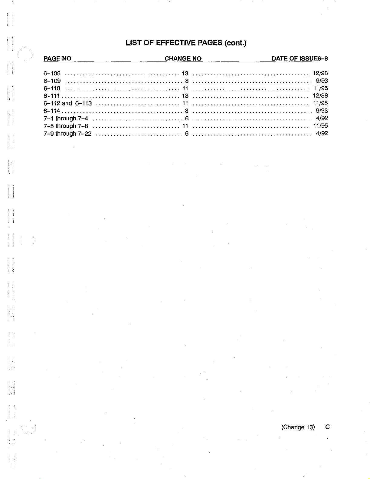
LIST
OF
EFFECTIVE
PAGES
(cont.)
PAGE
7-1
through
7-5
through
7-9
through
NO
7-4
7-8
7-22
...
...
CHANGE
NO
DATE
OF
ISSUE6-8
(Change
13)
С

This
page
is
intentionally
left
blank.
D.
(Change
13)
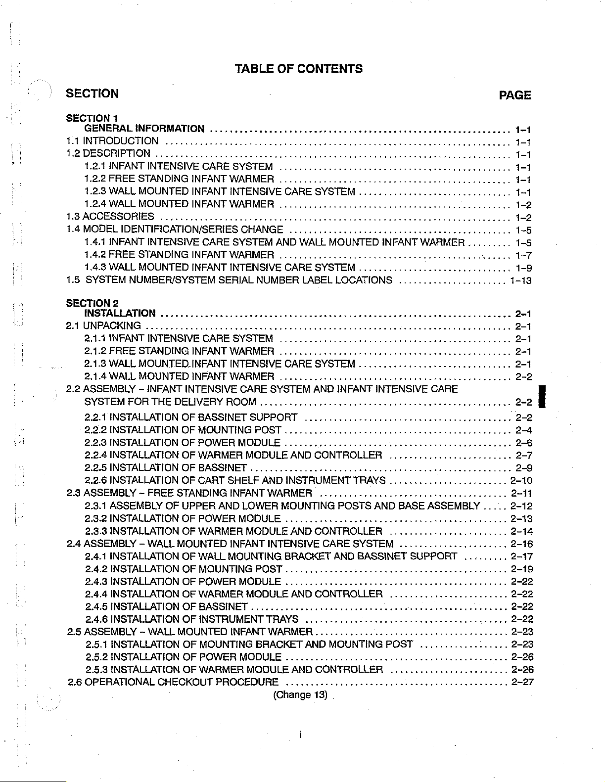
TABLE
OF
CONTENTS
SECTION
SECTION
1.1
INTRODUCTION
1.2
DESCRIPTION
1BACCESSORIES
1.4
MODEL
SECTION
2.1UNPACKING
2.2
ASSEMBLY
2.3
ASSEMBLY
2.4
2.5
2.6
1
GENERAL
1.2.8
WALL
1.2.4
WALL
IDENTIFICATION/SERIES
1.4.1
INFANT
1.4.2
FREE
2
INSTALLATION
2.1.3
WALL
2.1.4
WALL
SYSTEM
2.2.1
2.2.2
2.2.3
2.2.4
2.2.5
2.2.6
2.3.1
2.3.2
2.3.3
ASSEMBLY - WALL
2.4.1
2.4.2
2.4.3
2.4.4
2.4.5
2.4.6
ASSEMBLY ~ WALL
2.5.1
2.5.2
2.5.3
OPERATIONAL
FOR
INSTALLATION
INSTALLATION
INSTALLATION
INSTALLATION
INSTALLATION
INSTALLATION
ASSEMBLY
INSTALLATION
INSTALLATION
INSTALLATION
INSTALLATION
INSTALLATION
INSTALLATION
INSTALLATION
INSTALLATION
INSTALLATION
INSTALLATION
INSTALLATION
|
INFORMATION
..........
MOUNTED
MOUNTED
..............................
INTENSIVE
STANDING
.........
MOUNTED.INFANT
MOUNTED
-
INFANT
THE
-
FREE
CHECKOUT
INTENSIVE
DEHVERY
OF
OF
OF
OF
OF
OF
STANDING
OF
UPPER
OF
OF
MOUNTED
OF
OF
OF
OF
OF
OF
MOUNTED
OF
OF
OF
INFANT
INFANT
INFANT
NFANT
BASSINET
MOUNTING
POWERMODULE...............
WARMER
BASSINET
CART
POWER
WARMER
WALL
MOUNTING
POWER
WARMER
BASSINET
INSTRUMENT
MOUNTING
POWER
WARMER
INTENSIVE
WARMER
CARE
WARMER
0000
INTENSIVE
WARMER
ROOM
SHELF
INFANTWARMER
AND
INFANT
MOUNTING
INFANT
PROCEDURE
CHANGE
SYSTEM
CARE
SUPPORT
POST
MODULE
LOWER
MOCDULE
MODULE
POST
MODULE
MODULE
.................,....444
BRACKET
MODULE
MODULE
CARE
AND
WALL
S
00
ne K P K K S
CARE
SYSTEM
.............
AND
ccc
AND
INSTRUMENT
MOUNTING
...
AND
INTENSIVE
BRACKET
AND
TRAYS
WARMER
AND
.........
(Change
PAGE
SYSTEM
MOUNTED
K
SYSTEM
AND
CONTROLLER
cece
....................
CONTROLLER
CARE
CONTROLLER
...........
AND
MOUNTING
ο
νε
CONTROLLER
13)
...........................,...
INFANT
KK O K K O K KO O KK
n
.......,..........,...,........
INFANT
eee e terre
POSTS
AND
ενω ε νεο
cece
INTENSIVE
eee
TRAYS
AND
SYSTEM
BASSINET
ee
νο
cece
cee
enter
.................,......
eee
POST
WARMER
P
eee
nee
CARE
reat
eee
BASE
ASSEMBLY
ee r 0
SUPPORT
cere
eect
ε
κος
.............
ων
ω
ων
ρω
ν
ενο
ενω
κο
.........
eect
cece
εκ
εκ
déesse.
.........
K K o K
erence
iii
ennes
.....
.........
cence
κών κ ενω
ken
ewes
eee
..
ner
....
eee
ων
ως
1-
1-5
2-1
2-1
2-1
2-2
2-12
2-13
2-14
2-16
2-17
SECTION
2.6.1
2.6.2
2.7
CLEANING
ELECTRICAL
MECHANICAL
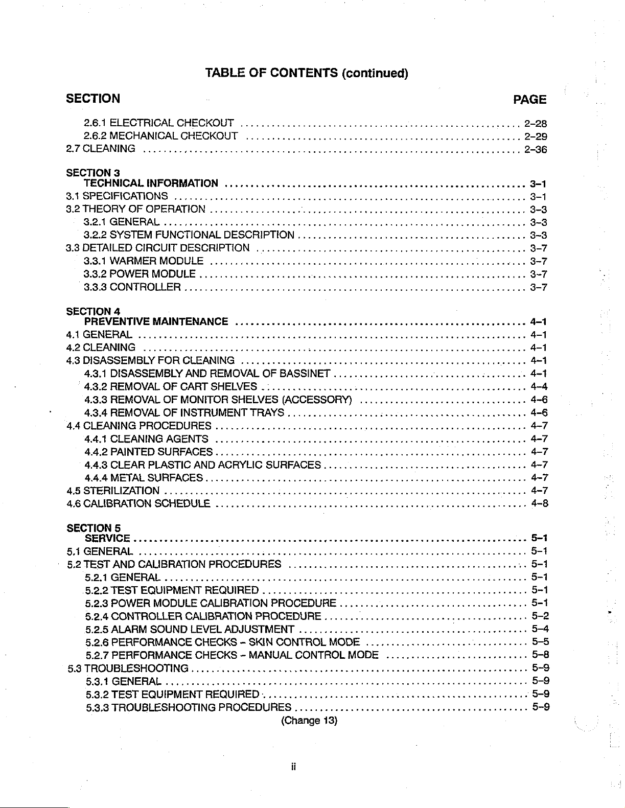
TABLE
CHECKOUT
CHECKOUT
OF
...
CONTENTS
(continued)
SECTION
3.1
SPECIFICATIONS
3.3
DETAILED
SECTION
4.1
GENERAL
4.2
CLEANING
4.3
DISASSEMBLY
4.4
4.5
4.6
3
TECHNICAL
3.21GENERAL.............
3.2.2
SYSTEM
3.3.1
WARMER
3.3.2
POWER
3.3.3
CONTROLLER
4
PREVENTIVE
4.3.1
DISASSEMBLY
4.3.2
REMOVAL
4.3.3
REMOVAL
4.3.4
REMOVAL
CLEANING
4.4.1
CLEANING
4.4.2
PAINTED
4.4.3
CLEAR
4.4.4
METAL
STERILIZATION
CALIBRATION
INFORMATION
FUNCTIONAL
CIRCUIT
MODULE
MODULE
MAINTENANCE
FOR
OF
OF
OF
PROCEDURES
AGENTS
SURFACES
PLASTIC
SURFACES.......
...............
SCHEDULE
.ν
εννοω
.................
DESCRIPTION
DESCRIPTION
CLEANING
AND
CART
MONITOR
INSTRUMENT
REMOVAL
SHELVES
SHELVES
TRAYS
...........
...................
eo
AND
ACRYLIC
κο
ννν
νο
κων
OF
BASSINET
(ACCESSORY)
に
SURFACES
ενω
τν
ーー
ρα
εο
νο
νεο νεα
εν
κεν
ες
아이
aires
............
トー
トー
トー
スー っ ーー
εε
νεο
νο
σσ
νε
ен
laa
トー に ーーーーーーー
νεο κ εκ ω ον
нннани:
4-6
SECTION
5.1
5.2
TEST
5.3
5
SERVICE
νι
GENERAL
AND
CALIBRATION
5.2.1
GENERAL に に
5.2.2
TEST
EQUIPMENT
5.2.3
POWER
5.2.4
CONTROLLER
5.2.5
ALARM
5.2.6
PERFORMANCE
5.2.7
PERFORMANCE
MODULE
SOUND
TROUBLESHOOTING
5.3.1
GENERAL
5.3.2
TEST
EGUIPMENT
5.3.3
TROUBLESHOOTING
이이
니이 이 이 이 아
PROCEDURES
ュー
REQUIRED
CALIBRATION
CALIBRATION
LEVEL
ADJUSTMENT
CHECKS - SKIN
CHECKS - MANUAL
«ο
οκ ν κο ν ον
.
i
REGUİRED......
PROCEDURES
아 피
미 마 이 이 이 이 아 미 이
に
PROCEDURE
PROCEDURE
し
CONTROL
CONTROL
νν
νοκ
ετεκ
ニーーー
1.0
(Change
ーーー
.....
て
MODE
MODE
εν
κε κ νε
13)
아 이 이 마 이 아 이 익 이
이 이 이 미 이 니
ーー
60600060 e tenké
スー
リー
て
ーー
トー
トー
ーーーーー
トー
Lei
ーー
レー
し
トー
ーーー
ーー
トー
バーー
トーー
............................
νε
εκ
ένεκεν
κε ε νε
εκτ
εν
5-1
5-1
5-1
5-1
5-1
5-1
5-2
5-4
5-5
5-8
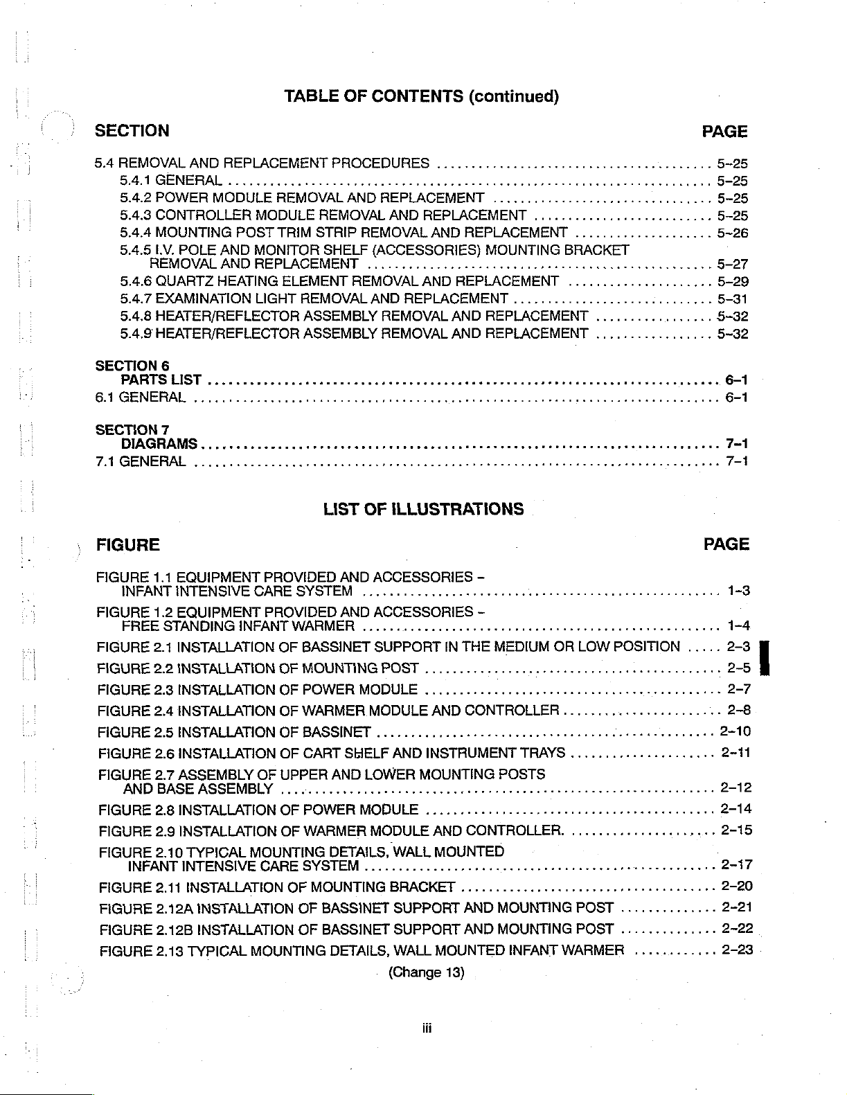
LIST
OF
ILLUSTRATIONS
(continued)
FIGURE
FIGURE
FIGURE
FIGURE
FIGURE
FIGURE
FIGURE
FIGURE
FIGURE
FIGURE
FIGURE
FIGURE
FIGURE
FIGURE
FIGURE
FIGURE
FIGURE
FIGURE
FIGURE
FIGURE
FIGURE
FIGURE
FIGURE
FIGURE
FIGURE
FIGURE
FIGURE
FIGURE
FIGURE
FIGURE
FIGURE
6.9A
PARTS
BOARD
(INFANT
INTENSIVE
(FREE
(WALL
WITH
REGULATION
RADIOGRAPHY
INFANT
DAGRAM................
WARMER
PCB1
6.10
PARTS
INTENSIVE
CARE
6.11
PARTS
6.12
PARTS
6.13
PARTS
6.14
PARTS
6.15
PARTS
STANDING
6.16
PARTSLOCAMON
6.17
PARTS
6.18
PARTS
6.19
PARTS
6.20
PARTS
OXYGEN
6.21
PARTS
AUXILIARY
6.22
PARTS
6.23
PARTS
6.24
PARTS
6.25
PARTS
6.26
PARTS
6.27
PARTS
INTENSIVE
6.28
PARTS
6.29
PARTS
6.294
6.30
6.31
6.32
6.33
6.33
6.34
6.35
7.1
WARMER
PARTS
PARTS
PARTS
PARTS
PARTS
PARTS
PARTS
SCHEMATIC
HOUSING
(SERIES
ASSEMBİY
LOCATION
01
LOCATION
CARE
SYSTEM,
LOCATION
LOCATION
LOCATION
LOCATION
LOCATION
INFANT
LOCATION
LOCATION
LOCATION
LOCATION
ONLY)
LOCATION
TANK
LOCATION
LOCATION
LOCATION
(DMR)
CASSETTE
LOCATION
LOCATION
LOCATION
CARE
LOCATION
LOCATION
MODULE
LOCATION
LOCATION
LOCATION
LOCATION
LOCATION
LOCATION
LOCATION
DIAGRAM,
DIAGRAM,
POWER
DIAGRAM,
SYSTEM,
AND
WALL
DIAGRAM,
DIAGRAM,
DIAGRAM,
DIAGRAM,
DIAGRAM,
WARMER)
DIAGRAM,I.V.POLEFACKAGE.............................
DIAGRAM,
DIAGRAM,
DIAGRAM,
DIAGRAM,
DIAGRAM,
PROVISION
DIAGRAM,
DIAGRAM,
................
DIAGRAM,
DIAGRAM,
DIAGRAM,
DIAGRAM,
ЗУЗТЕМ
DIAGRAM,
DIAGRAM,
ASSEMBLY,
DIAGRAM,
DIAGRAM,
DIAGRAM,
DIAGRAM,
DIAGRAM,
DIAGRAM,
DIAGRAM,
POWER
POWER
MODULE)
WARMER
WALL
PACKAGE
HOLDER
......
еее
MOUNTED
MOUNTED
WARMER
HEATER/REFLECTOR
BASSINET
FREE
STANDING
WARMER
ーー に ーー
CART
MONITOR
MONITOR
OXYGEN
OXYGEN
TANK
AUXILIARY
A.C.
WALL
SHELF
BRACKET
уни
DIRECT
PACKAGE.
SHELF
RECEPTACLE
MOUNTED
BASSINET
WALL
MOUNTED
90°
ия
нии
DRAWER
OXYGEN/AIR
PCB4
ASSEMBLY,
RESUSCITATION
RESUSCITATION
CLASSIC
DELUXE
MODULE
(Change
MODULE
MODULE
INFANT
MODULE
ASSEMBLY
MODULE
SHELF
SHELF
DELIVERY
DELIVERY
(WALL
OXYGEN
иене
MAGNIFICATION
ASSEMBLY, X-RAY
SUPPORT
PIVOT,
MODULE
RESUSCITATION
RESUSCITATION
(SERIES
0
13)
POWER
ASSEMBLY
INFANT
WARMER)
SUBASSEMBLY
ASSEMBLY
INFANT
ASSEMBLY
に に に に に に ーー
PACKAGE
AND
vee
K
CYLINDER
ーー
PACKAGE
UNIT
PACKAGE
SYSTEM
AUXILIARY
ASSEMBLY
SUPPLY
...................
BOX
©
FRAME
INFANT
PARTS LOCATION
K
KIT
...,..,...,......,.......
MOTHERBOARD
MODULE
MODULE
00)
AND
K
SUPPLY
.
WARMER
トト
トート
.........................
.....................
に
に
e
TANK
.....,,..........,...
K K K
ASSEMBLY
teeter
WARMER
MOUNTING
K K P
K
CASSETTE
een
ASSEMBLY
K P
K K K
(Sheet
(Sheet
MODULE
MODULE
1)
2)
K
PAGE
nens
.............-
ーー
OXYGEN)
rr
HOLDER
..............
..............
・
BRACKET
.............
............
............
............
.............
K
K
..
K
ини
..
K
........
K
..
νο
ον
6-42
6-56
6-60
6-64
6-66
6-68
6-70
6-72
6-74
6-76
6-78
6-80
6-82
6-84
6-86
6-90
6-92
6-96
6-100
6-102
6-104
6-106
6-107
6-110
6-112
7-3/4
LIST
OF
ILLUSTRATIONS
(continued)
FIGURE
FIGURE
FIGURE
FIGURE
FIGURE
FIGURE
FIGURE
FIGURE
FİGURE
FIGURE
AND
BOARD
BOARD
7.1A
WARMER
7.2
7.3
7.4
7.5
7.6
7.7
7.8
7.9
FLOWCHART
FLOWCHART
FLOWCHART
FLOWCHART
SCHEMATIC
HOUSING
SCHEMATIC
SCHEMATIC
PCB2
SCHEMATIC
SCHEMATIC
WIRİING
SCHEMATIC
PCB2,
SCHEMATIC
SCHEMATIC
5.1
CONTROLLER
5.2
WARMER
5.3
POWER
DIAGRAM,
DIAGRAM,
DIAGRAM,
DIAGRAM,
DIAGRAM,
DIAGRAM,
DIAGRAM,
DIAAGRAM,MOTHERBOARD,PCB4
DIAGRAM,
MODULE
MODULE
POWER
CONTROLLER
CONTROLLER
CONTROLLER
CONTROLLER
POWER
MODULE
MODULE
CONTROLLER
SPEAKERASSEMBLY,PCB4
LIST
OF
TROUBLESHOOTING
TROUBLESHOOTING
MODULE
een
(SERIES
DISPLAY
MEASUREMENT/DIGITAL
CONTROL
MOTHERBOARD
ANDWARMER
MEASUREMENT/DIGITAL
01)
BOARD
K
BOARD
........................
S
............................
........................
eee
PCB4
PCBS
PCB4
ener
.................
K k ee
...............
teense
n
n
.............
anan
FLOWCHARTS
TROUBLESHOOTING_...........................-
....
PAGE
ene
7-11/12
7-13/14
7-15/16
7-17/18
7-19/20
7-21/22
PAGE
7-5/6
7-7/8
7-9/10
5-11
TABLE
TABLE
TABLE
TABLE
TABLE
TABLE
TABLE
TABLE
TABLE
TABLE
TABLE
TABLE
TABLE
TABLE
TABLE
1.1
SERIES
1.2
SERIES
1.3
SERIES
1.4
SERIES
1.5
SERIES
1.6
SERIES
1.7
SERIES
1.8
SERIES
1.9
SERIES
1.10
1.11
1.12
1.13
1.14
SERIES
SERIES
SERIES
SERIES
SERIES
LIST
CHANGE - CART/BASSINET,
CHANGE - WARMER
CHANGE - POWER
CHANGE - CONTROLLER,
CHANGE - CONTROLLER,
CHANGE - WARMER
CHANGE ~ POWER
CHANGE - CONTROLLER,
CHANGE - CONTROLLER,
CHANGE - WARMER
CHANGE - POWER
CHANGE - CONTROLLER,
CHANGE - CONTROLLER
CHANGE 0 WARMER
MODULE,
MODULE,
MODULE,
MODULE,
MODULE,
MODULE,
MODULE
(Change
OF
TABLES
MODEL
MODEL
MODEL
MODEL
MODEL
MODEL
MODEL
MODEL
MODEL
MODEL
MODEL
MODULE,
CB78-1
CM78-1
CM78-2
CM78-1
CM78-2
MODEL
CM78-1
(90°
PIVOT),
13)
WR78-1
PM78-1
WFS78-1
PM78-1
WR78-1
PM78-1
MODEL
...................
and
1E
and
1E
and
1E
and
1E
....................
............,................
..................
and
1E
and
1E
..................
............................
CM78-2
MODEL
...................
WRP78-1
AND
1E...
1-12
-
vi

LIST
OF
TABLES
(continued)
TABLE
TABLE
TABLE
6.23
(ACCESSORY)
6.24
CASSETTE
(ACCESSORY)
TABLE
6.25
[πως
TABLE
6.26
(ACCESSORY)
TABLE
TABLE
TABLE
TABLE
TABLE
TABLE
TABLE
TABLE
TABLE
TABLE
6.27
WALL
6.28
6.29
6.29A
6.30
6.31
6.32
6.33
6.34
6.35
AUXILIARY
DIRECT
HOLDER
OXYGEN
MAGNIFICATION
上
SHELF
ο
A.C.
ASSEMBLY,
μμ
RECEPTACLE
MOUNTED
BASSINET
WALL
WARMER
DRAWER
OXYGEN/AIR
PCB4
RESUSCITATION
CLASSIC
DELUXE
SUPPORT
MOUNTED
MODULE
MODULE
ASSEMBLY,
RESUSCITATION
RESUSCITATION
PACKAGE,
X-RAY
BOX
スス
スー
INFANT
INFANT
ASSEMBLY,
KIT,
CYLINDER
MOTHERBOARD,
MODULE,
SUPPLY
REGULATION
RADIOGRAPHY
PARTS
ーー
スー
CASSETTE
ΑΜ
ASSEMBLY,
トー
INTENSIVE
FRAME
ASSEMBLY,
WARMER,
PARTSLIST
MOUNTING
PARTS
MODULE,
MODULE,
LIST
90°
LIST
ASSEMBLY,
(DMR)
スー
トー
スー
HOLDER,
ΜΕ...
PARTS
CARE
PARTS
PIVOT,
BRACKET,
PARTS
PARISLIST
PARTS
LIST
スー
ーー し ーーーーーーーーーーーーーーー…ーー
SYSTEM,
PARTS
LIST
PARTS
LIST
..............
LIST
PARTS
een
nen
トーー
ーー
ーーーーーーーー…
PARTS
LIST
PARTS
LIST
...............,.,...,....
............
LIST
cece
cece
cece e cence
PARTS
LIST
.........,....,..,............
........................
.................,..,........
LIST
ee
Eee K K
LIST
...............
eet
...........,....,..
erir
K
K
k
PAGE
6-79
6-81
6-83
6-85
6-87
6-103
6-105
6-108
6-111
6-113
(Change
viti
13)
TABLE
OF
DEFINITIONS
AND
SYMBOLS
NOTE,
NOTE: A Note
looked. A Note
IMPORTANT:
CAUTION: A Caution
age
IMPORTANT,
is
inserted
may
Similar
or
destruction
WARNING: A Warning
to
the
operation,
death
of
the
operator
of
CAUTION,
in
text
also
be
used
to a Note
is
inserted
the
equipment.
is
inserted
cleaning,
or
to
point
to
clarify
but
used
in
text
and
maintenance
patient.
AND
out
procedures
apparently
where
to
call
in
text
WARNING
greater
attention
to
call
attention
of
or
conditions
contradictory
emphasis
to a procedure
the
equipment
which
or
is
to
dangerous
may
confusing
required.
which,
which
if
or
may
not
otherwise
situations.
followed
hazardous
result
be
misinterpreted
exactly,
conditions
in
can
personal
or
over-
lead
to
dam-
inherent
injury
or
|
(Change
8)

(This
page
is
intentionally
left
blank.)
(Change
8)
GENERAL
HCS
INFORMATION
1.1
INTRODUCTION
This
manual
*
“Infant
©
Free
Standing
®
Wali
Mounted
@
Wail
Mounted
manual
The
equipment
1.2
DESCRIPTION
1.2.1
INFANT
DELIVERY
The
Infant
consists
Controller
which
of a Cart
are
provides
Intensive
Infant
Infant
Infant
is
intended
are
provided
INTENSIVE
ROOM
Intensive
and
Assembly.
mounted
instructions
Care
System
Warmer
intensive
Warmer
for
use
in a separate
CARE
Care
System
Bassinet
The
Infant
on
the
Bassinet
SECTION
GENERAL
for
installation,
and
Infant
Intensive
System
Care
System
only
by
SYSTEM
and
Assembly, a Warmer
Intensive
7830
System
7840
trained,
Operator’s
AND
Infant
Care
Support
qualified,
Intensive
System
at
1
INFORMATION
maintenance,
Care
System
7820
manual.
INFANT
the
rear
service
is
of
personnel.
INTENSIVE
Care
System
Module,
also
equipped
the
Bassinet.
and
repair
of
the
for
the
Delivery
Instructions
CARE
for
the
with a built-in
with
two
following
Room
for
SYSTEM
Delivery
Examination
removable
equipment:
System
the
operator
FOR
THE
Room
Light,
instrument
7810
of
(Figure
and
trays
I
the
1.1)
a
U
©
Cart
and
Bassinet — The
a
mounting
e
Warmer
examination
*
Controller — Provides
1.2.2
FREE
The
Free
except
be
height
to
positions
specified
©
©
1.2.3
The
(Figure
on a wall.
that
swiveled
of
the
the
various
Warmer
examination
Controller — Provides
WALL
Wall
1.1)
for
Module — The
or
STANDING
Standing
it
is
not
from
base
styles
to
accommodate
distance
Module 一 The
MOUNTED
Mounted
except
the
Warmer
special
Infant
equipped
side
to
is
only 9 cm
of
between
or
special
Infant
that
itis
Bassinet provides
Module
Warmer
procedures.
either
manual
INFANT
Warmer
side.
“bassinets.”
either
INFANT
Intensive
WARMER
(Figure
with a Cart
The
mobile
(3-1/2 inches)
The
bassinets
the
Warmer
procedures.
which
lower
manual
INTENSIVE
Care
not
equipped
maximum
and
Bassinet.
Module
heat
contro!
1.2)
and
Bassinet
base
and
Warmer
have
surface
Module
heat
of
control
CARE
System
with a Cart
visibility
houses a heating
or
automatic
is
functionally.
Assembly
is
designed
the
base
Posi
different
the
Warmer
houses a heating
or
identical
and
for
use
has a single
can
be
assembled
mattress—to—floor
Module
automatic
SYSTEM
is
functionally
Assembly
identical
andis
and
access
element
skin
the
with a variety
center
and
element
skin
designed
to
and
temperature
to
the
Warmer
support
to
the
and
temperature
to
the
the
infant;
an
Examination
control.
Infant
Intensive
Module
of
“bassinets.”
leg
provide one
heights
maitress
Infant
for
while
surface.
an
Examination
control.
Intensive
mounting
the
Cart
Care
is
fixed
to
make
of
three
maintaining
Care
ina
fixed
provides
Light
System
and
cannot
The
overall
it
adaptable
height
Light
System
position
for
the
for
©
{Change
14
8)
 Loading...