

Air-Shields 100V, 110V, 120V, 220V, 240V User manual
HCS
INSTALLATION
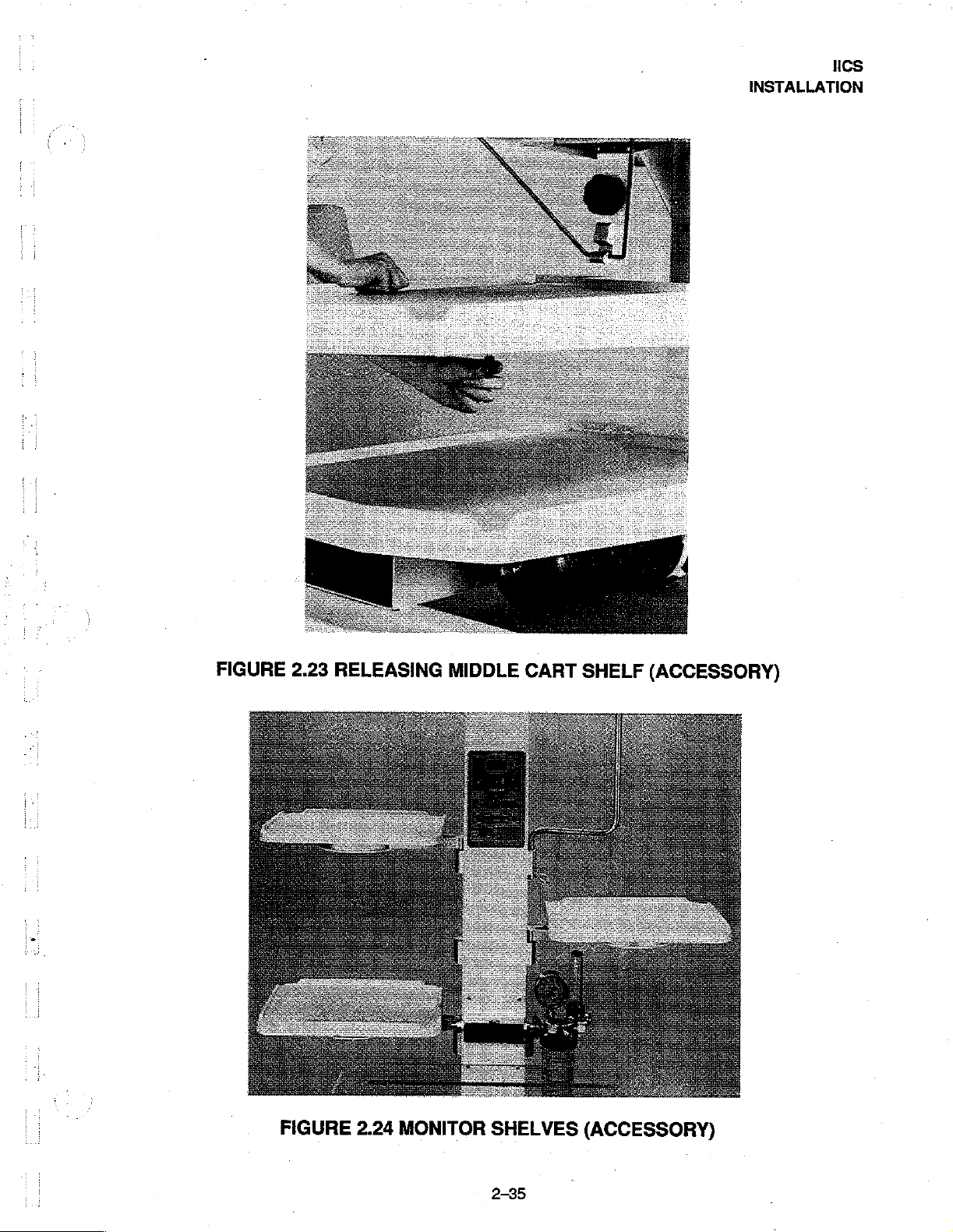
FIGURE
2.23
RELEASING
MIDDLE
CART
SHELF
(ACCESSORY)
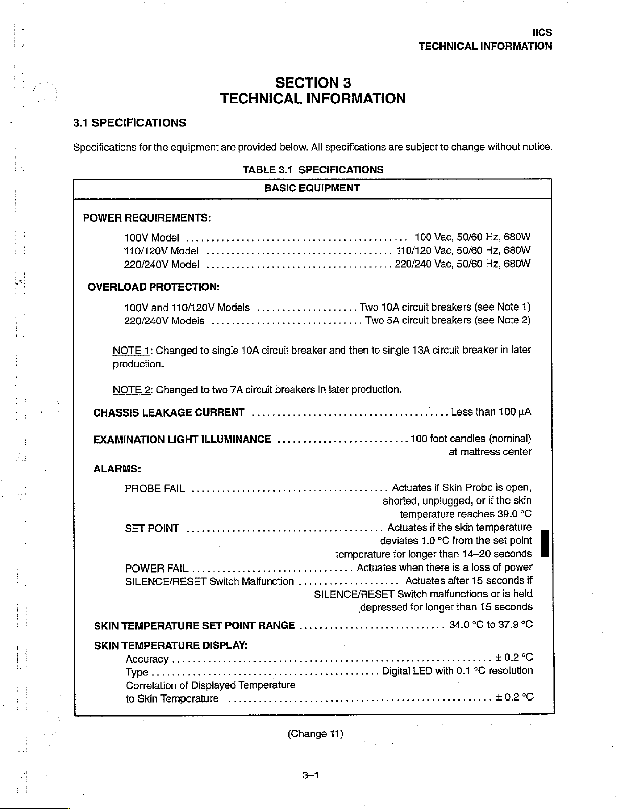
FIGURE
2.24
MONITOR
SHELVES
2-35
(ACCESSORY)

ICS
INSTALLATION
2.7
CLEANING
The
equipment
should
be
cleaned
as
necessary
using
the
procedures
given
in
Section
4
of
this
manual.
2-36
TECHNICAL
HCS
INFORMATION
3.1
SPECIFICATIONS
Specifications
POWER
OVERLOAD
REQUIREMENTS:
100V
110/120V
220/240V
100V
220/240V
NOTE
production.
for
the
equipment
Model
Model
Model
PROTECTION:
and
110/120V
Models
1:
Changed
SECTION
TECHNICAL
are
provided
TABLE
BASIC
...,.........................,...,...
..................,.........,........
Models
.............................,
to
single
...............,...,
10A
circuit
INFORMATION
below.
3.1
All
SPECIFICATIONS
EQUIPMENT
breaker
3
specifications
Two
and
then
rr
Two
to
are
kenese
110/120
220/240
10A
circuit
5A
circuit
single
subject
100
Vac,
Vac,
Vac,
breakers
breakers
13A
circuit
to
change
50/60
50/60
50/60
(see
(see
breaker
without
Hz,
680W
Hz,
680W
Hz,
680W
Note
Note
in
later
notice.
1)
2)
NOTE
CHASSIS
EXAMINATION
ALARMS:
SKIN
SKIN
2:
Changed
LEAKAGE
РВОВЕ
SETPOINT
POWERFAL..............................
SILENCE/RESET
TEMPERATURE
TEMPERATURE
Accuracy
Type
Correlation
to
Temperature
Skin
РАШ
CURRENT
LIGHT
.......-
...............
.0
of
Displayed
to
two
7A
circuit
ILLUMINANCE
иене
1...
Switch
SET
DISPLAY:
Malfunction
POINT
RANGE
Temperature
.......................
breakers
.....................
in
later
production.
νο
ον
етяниня
aa
temperature
Actuates
....................
SILENCE/RESET
depressed
.......................:.....
...
shorted,
deviates
0.00
Actuates
Actuates
for
lee
νο ο να
“....
100
foot
if
unplugged,
temperature
if
the
1.0
°C
longer
than
when
there
Actuates
Switch
malfunctions
for
longer
Less
candles
at
mattress
Skin
Probe
reaches
skin
from
14-20
is a loss
after
than
34.0
than
100
pA
(nominal)
center
is
open,
or
if
the
skin
39.0
°C
temperature
the
set
point
seconds
of
power
15
seconds
or
is
held
15
seconds
°C
to
37.9
+0.2
+0.2°C
上
if
°C
°C
(Change
3-1
11)
HCS
TECHNICAL
INFORMATION
SKIN
TEMPERATURE
TEMPERATURE
MANUAL
WARMER
NOMINAL
TABLE
VARIABILITY
EQUILIBRIUM
HEAT
Height
Height
Width
МаНгез$
Mattress
Weight..............................
WarmerModuleSwivel..........................
Matiress
Mattress
CONTROL
MODULE
DIMENSIONS
ο
ο
SWIVEL
(Maximum)
(Alternative
(With
Warmer
iii
МОМ
Length
Height
Height
.....................,..........
(Not
—
INFANT
......................................
lower
Module
............
........................................
(High
position)
(Low
position)
3.1
SPECIFICATIONS
BASIC
AT
provided
INTENSIVE
position)
in
Center
.....................................
...................................
EQUIPMENT
on
Free
Standing
CARE
........................
position)
SYSTEM
PPP
(CONT.)
Fully
adjustable
maximum
..................
heater
Warmer)
,
reeeee
κ
65°
power
................
77
74.75
43
21
26
εν
ερ
ο
either
side
이
(560W
center
inches
inches
28
inches
inches
inches
inches
ρος
185
of
center
이
이이
from
nominal)
either
position
(195.6
(189.9
(109.22
(53.34
(66.04
lbs
39
36.75
0.2
°С
zero
to
65°
side
of
cm)
cm)
(71
cm)
cm)
cm)
cm)
(84
kg)
position
inches
inches
NOMINAL
NOMINAL
NOMINAL
DIMENSIONS
Height(Maximum)
Height
Height
Height
Width
Depih
Weight
Height
Width
Depth
Weight
Height
Width
Depth
Weight
Warmer
(intermediate
(Low
position)
of
Base
(Maximum)
.............................
DIMENSIONS
(Unmounted)
(With
Warmer
(Including
.........
DIMENSIONS
(Unmounted)
(With
Warmer
(Including
ille
Module
AND
WEIGHT
i
position)
......................................
................
μμ
AND
WEIGHT
........
Module
Wall
Bracket)
i
eee
AND
WEIGHT
..............,.......................
Module
Wall
Bracket)
Swivel
..........................
—
FREE
STANDING
...............................
和
------.
—
WALL
in
Center
...............................
~
in
Center
.
.........,............,........
Position)
WALL
Position)
MOUNTED
ян
MOUNTED
INFANT
..................
..............
INFANT
iii.
INFANT
65°
WARMER
77
74
71
이.
38.5
eue
INTENSIVE
aaa
59
46
ce
WARMER
53
12.5
either
side
inches
inches
inches
3.5
inches
28
inches
inches
103
CARE
inches
22
inches
inches
124
inches
inches
38
inches
44
of
center
(195.6
(188
(180
(9
(71
(98
lbs
(47
SYSTEM
(150
(56
(117
Ibs
(56
(135
(31.75
(97
Ibs
(20
position
cm)
cm)
cm)
cm)
cm)
cm)
kg)
cm)
cm)
cm)
kg)
cm)
cm)
cm)
kg)
3-2
TECHNICAL
HCS
INFORMATION
TABLE
ENVIRONMENTAL:
Ambient
Humidity
Vibration
Alitude
OXYGEN
Oxygen
Oxygen
MONITORSHELFLOADING*
CARTSHELFLOADING*..................
Operating
LL...
and
..........................................
DELIVERY
From
From
Temperature
Shock
SYSTEM
Wall
Source
Суйлаег
................................,..
......
.............................
3.1
SPECIFICATIONS
BASIC
REQUIREMENTS:*
...........,..............,..........
EQUIPMENT
.....................
eee
ACCESSORİES
000.
이
(CONT.)
eh
이 이 이
이이
68
R
이 이 이
up
50
or
up
°F
еее
Sea
to
Ibs
to
(20
Normal
level
이
이이.
40
(22.7
50
Ibs
°C)
нал.
to
Ibs
kg)
(22.7
to
86
nursery
1.9
miles
50
psi
up
to
(18
kg)
per
kg)
°F
(30
0
to
95%
handling
(3
km)
nominal
2500
psi
per
shelf
total
side
per
shelf
°C}
PHOTOTHERAPY
“infant
“Infant
3.2
3.2.1
This
Controller
3.2.2
WARMER
The
minimum
either
examination
provides
intensive
THEORY
GENERAL
section
and
SYSTEM
radiant
discomfort
manual
added
Intensive
OF
contains
Power
FUNCTIONAL
MODULE
heat
from
heater
light
which
illumination
SYSTEM
Care
System
Care
System
OPERATION
a
system
Module
the
vented
to
attending
control
or
is
controlled
of
ies
and
Wall
Only.
functional
used
DESCRIPTION
personnel.
automatic
the
description
in
the
equipment.
hood
is
directed
by
a
switch
mattress
Mounted
The
Warmer
skin
temperature
on
area.
(Nominal
Infant
of
the
equipmentand
A
system
by
parabolic
is
the
front
light
energy
400-500
Intensive
controlled
control.
of
Care
block
diagram
reflectors
by
Located
the
Warmer
output
nanometer
System
detailed
a
is
onto
the
single
in
the
Module.
Theory
shown
nn
k
9uW/cm2/nm
at
center
wavelength)
Only.
of
Operation
in
Figure
bassinet
Controller
Warmer
which
The
examination
maltress,
ofthe
3.1.
mattress
provides
Module
is
with
an
light
33
CS
TECHNICAL
CONTROLLER
When
operated
be
adjusted
utilizes
adjust
switches
a
the
permit
Skin
ALARMS
Each
time
audible
Skin
and
alarm
Temperature
manual
INFORMATION
in
the
from
zero
Temperature
heat
output
adjustment
the
unit
is
are
functional.
Control
alert
when
Manual
to
maximum
of
the
turned
Mode);
in
Manual
Control
Probe
Warmer
of
skin
on,
Alarms
settings.
connected
temperature
an
automatic
are
probe
Control.
Mode,
When
Module
provided
failure
the
between
to
set
test
sequence
and
Controller
operated
the
maintain
point
and
for
power
unplugged
permits
in
the
Skin
Temperature
Controller
a
desired
a
digital
is
initiated
failure,
probe,
heat
output
input
and
preset
to
high
skin
display
SILENCE/RESET
verify
and
provides
that
tow
of
the
Warmer
Control
Mode,
the
infant
temperature.
temperature
the
visual
skin
temperature
switch
Module
the
Controller
to
automatically
Thumbwheel
readout.
displays
and
(when
malfunction,
to
the
in
POWER
audible
SET
high
FAIL.
alarm
POINT
SET
continuous
until
the
alarm
depressing
corrected
circuit
within
will
automatically
light.
If
power
will
sound
(HIGH).
POINT
audible
alarm
alarm
condition
the
SILENCE/RESET
14-20
to
the
unit
continuously.
if
the
temperature
will
occur
will
sound
is
corrected.
minutes,
reset.
is
interrupted
When
sensed
after a 14-20-second
and
the
heater
In
Model
Switch;
the
The
SILENCE/RESET
however,
audible
alarm
for
any
power
by
the
is
CM78-2,
will
(Change
reason,
is
restored,
skin
turned
the
the
indicator
resume.
Switch
11)
the
the
probe
delay.
off.
In
audible
will
When
must
POWER
alarm
is 1 °C
The
Model
portion
continue
the
be
actuated
FAIL
circuit
above
SET
POINT
CM78-1,
of
the
to
alarm
to
indicator
is
self-resetting.
the
set
point
indicator
this
alarm
alarm
can
flash.
If
the
condition
turn
off
the
will
light
and
temperature,
will
flash,
cannot
condition
is
steady
be reset
be
silenced
is
corrected,
ALARM
the
a
a
by
not
the
3-4
104
39080
Е
3243715/1
3535
fad)
|
=
=
277919
135
2903
=
<
VA
umd
EN
es
《
는
ZETA
ATdSIQ
6970)
TWOINVHOAW
AVI
OL
|
Q
304)
ZAH
AY
1ASIO
y
ЗА
3A31
BL
wie
50697
01
+
22-
NIVO
ANTI
139430
A0GINOI
(1929
1IWIT
Ad
1
は
Aero
83009
37009
an
NY
너
1081003
60340
Ang
从
(O3DAS
nao
AGro——
+
o
tr
[au
Addns
BOVIIOA
ONISNIS
INIT
ROZ
woud
!
CAE
HIH
(awvAl
(9319)
|
HOLIMS
AdYd3HLOLOHd
TECHNICAL
-
AdVB3H101OHd
VX
ics
INFORMATION
нот
|
liv
1d
135
{2
38044
924)
OV
도
lesa
SONY
703
MHD
wo
38044
NIS
SOTWNY
(2
839),
|
ST
2
5
NS
625-055
NS
1d
135
;
NOISIDR
say
=
.
ANYA
1
|
>
し
し
ーー
A
|
{ved
Vol
(ve)
VS
HOLIMS
=
440/NO-
ㅣ
|
e
B
awa
sit/oor
|
|
|
RE]
20060
|
|
|
240/N0
„азов
09
A
ENV
(BONZI)
og
os
—
|
=
(23100338)
ME
VS
1090/05
I
|
|
广
一
一
一
一
一
ο
o
ο
|
|
"HOLIMS
LHO
340/N0
Ol
ama
O
9NVHO
NH1
.
VOT
34V
289
NV
199
“1
SION
"NO119nQ0dd
“NOTLONGOUd
VET
931V1
331V1
NI
NI
VZ
01
qAOM3M
39NVHO
289*(NO1190Q0dd
289
qNV
99
?
』Sdfd)
SION
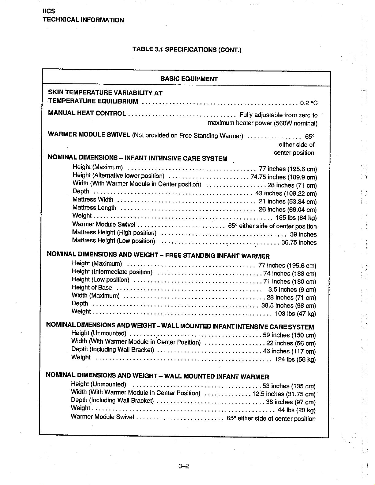
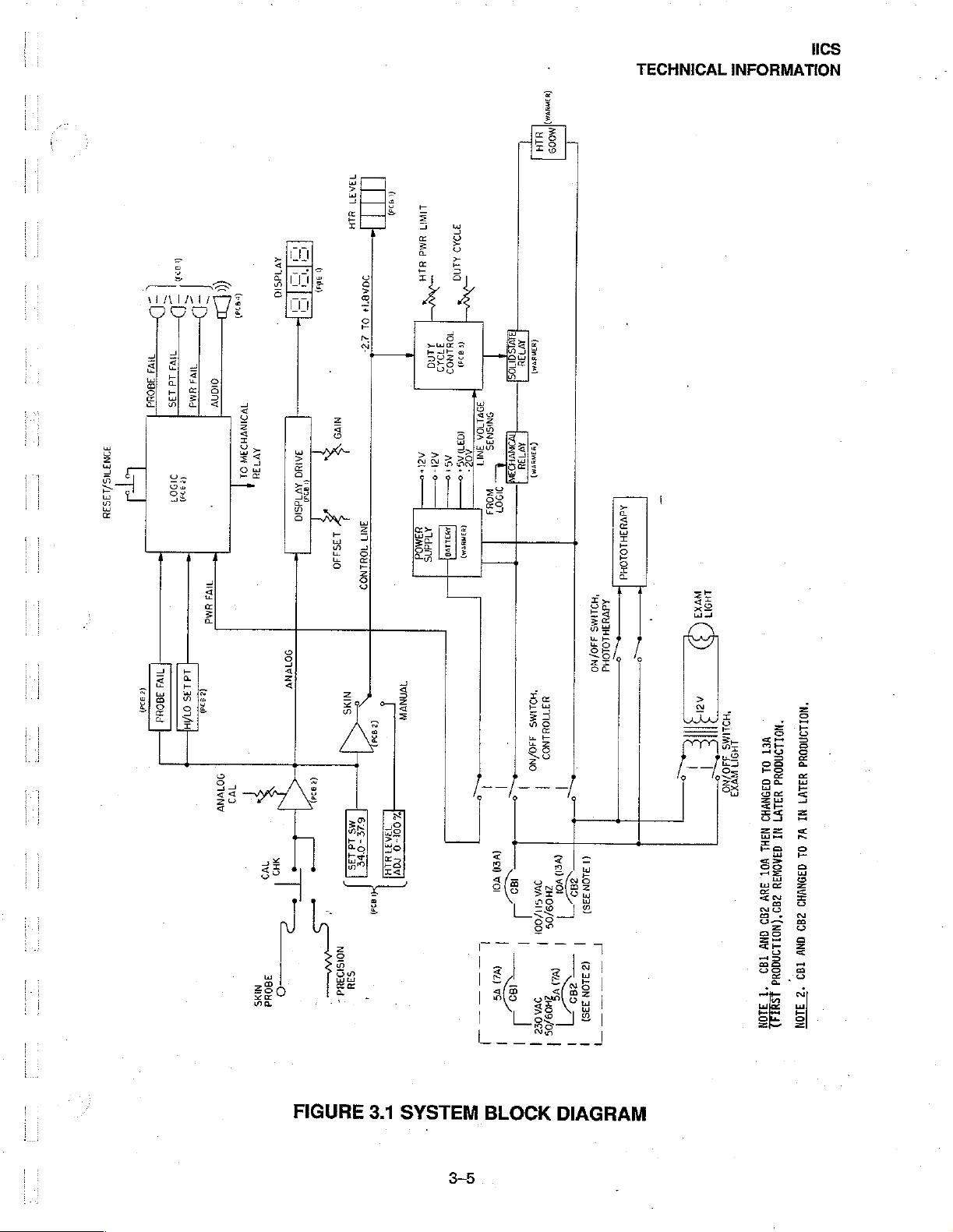
FIGURE
3.1
SYSTEM
3-5
BLOCK
DIAGRAM

CS
TECHNICAL
INFORMATION
NOTE:
°C
alarm
if
not
below
set
indications
follows).
SET
POINT
set
point
on/one
silenced
condition
correcied,
cease
During
visual
warm-up
minute
NOTE:
silenced
PROBE
(LOW).
alarm
off
chirping
by
is
not
the
to
flash).
initial
SET
POINT
or
until
period,
The
SILENCE/RESET
to
allow
FAIL.
14—20-second
chirping
is
PATIENT
in
alarm
corrected.
PROBE
the
event
of a PATIENT
manually
point,
the
will
will
reset
system
now
Ifthe
occur
alarm
depressing
corrected
circuit
will
The
SILENCE/RESET
warm-up
of
alarm
the
skin
the
low
SET
internal
If
the
skin
delay.
The
will
sound,
The
PROBE
is
used
when
the
sensed
changes
cease
if
temperature
the
to
a
sensed
sensed
after a 14-20-second
will
sound,
the
SILENCE/RESET
within
automatically
the
infant,
will
flash
temperature
TEMP
circuitry
temperature
display
and
the
FAIL
for
monitoring
PROBE
but the
14-20
if
the
but the
alarm
switch
to
reset.
will
heater
alarm
failure
minutes,
reset
must
infant’s
audible
is
within 1 °C
returns
must
Failure
probe
blank,
will
will
also
during
or
temperature
low
set
point
temperature
by
the
skin
delay.
heater
will
Switch;
the
audible
(i.e
the
audible
be
actuated
skin
temperature
alarm
of
SET
to
normal
be
depressed
to
do
is
open,
shorted,
the
PROBE
be
turned
off.
sound
MANUAL
if
it
is
unplugged.
returns
alarm
returns
probe
The
remain
however,
to
is
automatically
POINT,
to
condition
to
is 1 °C
SET
POINT
on.
the
alarm
alarm
will
turn
off
is
whichever
will
more
function.
for
at
least 2 seconds
so
could
result
or
unplugged, a probe
FAIL
alarm
This
alarm
if
the
skin
temperature
Control,
the
set
point
and
set
point
below
the
indicator
The
audible
indicator
resume.
cease
the
steady
than 1 °C
silenced
is
in
alarm
indicator
cannot
PROBE
be
FAIL
and
the
temperature
the
heater
turns
(see
SET
POINT
set
point
temperature,
will
flash, a one-second
portion
will
When
and
ALARM
for
shorter.
reactivation.
will
flash, a one—second
reset
reaches
continue
the
the
light
below
the
first
After
after
the
alarm
until
alarm
of
the
alarm
will
Light.
the
14-20
audible
will
the
39.0
will
on
(LOW)
alarm
to
flash.
condition
remain
SET
the
initial
occur
alarm
°C.
not
be
falls
to
0.5
again.
The
which
alow
can
be
if
the
on
but
TEMP,
the
minutes
14-20
signal
after
on/off
condition
When
the
activated
is
of
is
a
SILENCE/RESET
audible
more
MANUAL:
seconds.
the
minutes
chirping
NOTE:
silenced
POWER
The
Module
Controller
The
heating
alarm
than
15
After 9 to
The
SILENCE/RESET
of
continuous
alarm
The
SILENCE/RESET
to
allow
MODULE
Power
and
Power
element
Module
overload
by
means
Module
SWITCH
will
sound
seconds.
13
heater
may
is
activated.
internal
plugs
of a plug-in
also
in
the
MALFUNCTION.
after a 15-second
This
alarm
cannot
minutes
switch.
operation
be
of
operation, a one-second
reset
for
If
the
circuit
have
switch
circuitry
into
protection
the
to
Warmer
is
provided
ribbon
provides
warmer
power
housing.
If
the
SILENCE/RESET
delay.
The
alarm
be reset
an
additional
is
elapsed,
must
be
reset.
Failure
until
13
not
reset,
the
MANUAL
depressed
to
to
do
Module. A detachabie
by
circuit
cable
located
to
the
phototherapy
(Change
will
also
the
alarm
audible tone
19
minutes
the
heater
is
indicator
for
at
least 2 seconds
so
could
result
power
breaker(s).
in
the
The
warmer
connectors,
11)
switch
sound
condition
if
the
is
(Manual
without
the
automatically
light
goes
in
alarm
cord
supplies
Power
housing.
examination
malfunctions, a continuous
switch
is
held
depressed
corrected.
Alert)
will
sound
every
heater
turning
turned
off,
and a one-second
after
off
the
off
by
when
audible
pressing
13
to
on/off
signal
reactivation.
line
Module
voltage
supplies
to
power
light,
and
the
warmer
Power
to
for
30
19
is
the
3.3
DETAILED
The
following
e.
Warmer
+
Power
+
Controller
3.3.1
WARMER
Refer
to
radiant
the
mattress
for
the
paragraphs
Module
Module
Figures
heat
for
infant
by a parabolic
optional
Phototherapy
CIRCUIT
MODULE
7.1
and
warming.
DESCRIPTION
contain
7.1A.
The
The
reflector.
Attachment.
detailed
Warmer
heater
The
Warmer
circuit
descriptions
Module
is
contained
Module
of
the
contains a 600
in a vented
also
contains
following
watt
quartz
hood
and
the
examination
TECHNICAL
components
heater
the
radiant
INFORMATION
of
the
(HTR1)
heat
is
light
and
1ICS
equipment.
that
provides
directed
onto
connectors
Power
housing.
application
Controller,
T2
application
3.3.2
Refer
supplies
to
When
to
secondary
(+)
and
unregulated
output
—16.
Rectifiers
provided
for
supply
POWER
to
Figures
all
ac
input
the
the
primary
output
+5
Vdc,
at
Filtering
the
The
in
power
connector
WARMER
windings,
of
J10—10
CR5
by
Warmer
interconnection
of
ac
turn,
of
power
MODULE
ac
and
Module
power
controls
to
the
to
the
7.1
and
de
power
to
examination
7.1A.
J1.
ON-OFF
winding
CR3
respectively.
+20
for
and
capacitor
one
feeds
Vdc
output
and,
these
CR6
of
power
feeds
voltage
These
in
conjunction
circuits
produce
C6.
is
supplied
is
made
the
Power
heater
phototherapy
Circuit
power.
The
Power
to
the
equipment.
breaker(s)
switch
transformer
bridge
regulators
outputs
at
J10-9.
is
provided
an
by
the
through
Module
light
connector
which
The
EXAMINATION
(DSi).
connectors
Module
Primary
provide
(S1)
on
the
Warmer
T1
through
rectifier
with
unregulated
VR1
are fed
The
negative
voltage
by
CR3
and
to
capacitors
Power
Module
supplies
The
PHOTOTHERAPY
(J11
plugs
into
ac
J2.
and
power
overload
Module
connectors
and
the
other
VR2
which
J10-5
and
(-)
output
regulator
+5
VR3, a regulated
C1
Vdc
output
(para. 3.3.2)
The
WARMER
de
power
LIGHT
the
J12).
Warmer
is
applied
ON-OFF
protection
is
set
to
J2,
feeds
in
turn,
produce
—6
and
J10-17
of
CR3
through
at
C5.
J10-3
which
ON-OFF
to
the
Controller
switch
ON-OFF
Module
through
through
for
the
ac
the
ON—1
J5,
and
J6.
rectifiers
produces
regulated
and—18.
—12
and
—4.
CR5
Vde
plugs
into
switch
(para.
(S3)
and
switch
connector
a
detachable
line.
position,
Transformer
an
Filtering
power
and
CR6.
outputs
CR3
also
unregulated
output
at
for
the
warmer
(81)
controls
3.3.3).
transformer
(S2)
power
T1
The
produces
J10—15
this
controls
J2
is
applied
has
positive
of
+12
—20
circuit
The
and
cord
two
Vdc
Vdc
and
an
is
Solid
state
(J10—7)
Relay
generated
Battery BT1
the
and
driver
event
of
relay
(SSR)
SSR
Q1
on
PCB2.
and
associated
primary
LO
and
K2
controls
(J10-8)
relay
The
circuit
power
heater
power
which
are
generated
K1
are
activated
provides a redundant
components
failure.
provide
during
by
the
the
operation.
on
the
signal
means
voltage
3-7
The
Coniroller
RELAY
of
necessary
Control
DRIVE
cutting
relay
off
to
activate
is
actuated
Board
(J10-20).
power
in
the
by
the
PCB3.
The
the
event
POWER
signals
contro!
of
an
FAIL
SSR
signal
alarm.
alarm
Hi
is
in
105
TECHNICAL
3.3.3
CONTROLLER
INFORMATION
DISPLAY
The
indicators,
BOARD — PCB1
Display
TEMPERATURE
The
analog
needed
converter
to
drive
includes
determined
capacitor
fo
provide
The
and
Trimpots
The
the
The
segments
decimal
and
proper
sensitivity
R12
sets
R2
diode
network
permissible
lamp
test
and
point
Board,
control
signal
the
by
the
is
used
of
the
the
and
R7
limits
function
giving
is
lighted,
PCB1,
mode
indicator
DISPLAY
inputs
from
seven
auto
zero
RC
network
to
reduce
operation
A/D
converter
voltage
set
the
reference
CR1, CR2,
caused
is
provided
a
reading
even
contains
the
and
the
Measurement/Digital
segment
and
current
R6
and
noise
of
the
auto
is
at
converters
and
CR3
by
the
temperature
by
U4
of
88.8.
when
the
digital
readout
switches
LED
displays,
limiting
C4
which
in
the
voltage
zero
and
determined
a
nominal
offset
and
is
used
to
which
drives
Note
that
line
input
for
for
calibration,
Board,
DS1
for
the
LED
gives
approximately
reference
integrator
by
the
voltage
2.0
volts
gain,
respectively.
provide
measuring
pin
37
the
decimal
range
is
skin
temperature,
reset
PCB2,
through
DS3,
drivers.
circuit.
circuits
reference
which
will
display
blanking
thermistor
of
the
A/D
point
exceeded,
and
control
are
by
The
number
one
reading
The
RC
in
the
A/D
provide
being
converter
is
driven
blanking
alarm
mode.
converted
the
A/D
of
per
network
converter.
at
pin
36.
a
sensitivity
when
the
either
high,
through
the
indicators,
Refer
to
to
the
digital
converter
readings
second.
R5,
C1
per
C3
and
Resistor
of
200
input
voltage
open
or
shorted.
lighting
R1
at
all
all
display.
heater
Figure
signals
U1.
The
second
is
a
bypass
C2
is
network
mV
per
is
outside
the
display
times,
output
7.2.
A/D
is
used
R114
°C.
so
the
The
A/D
which
insures
CONTROLS
The
CAL
measuring
probe
and
The
SILENCE
1.
IN
SKIN
A.
Silences
if
B.
Resets
C.
In
D.
In
automatically
2.
INTHE
converter
power
CHECK
circuit
will
calibration.
cause
RESET
TEMPERATURE
low
another
alarm
PROBE
Model
Model
CM78-1
CM78-2
MANUAL
uses
the
supply
switch,
the
temperature
switch,
SET
POINT
occurs
FAIL
overridden
CONTROL
system
tracking.
S2,
is
a
Depressing
$3,
CONTROL
alarm
within
alarm
resets
high
silences
if
MODE,
+5V
supply
The
LED
momentary
this
display
is
used
to
MODE,
for
nominally
the
period
only
after
SET
high
SET
another
it
and
supply
pushbutton
switch
to
read
reset
various
of
the
condition
POINT
POINT
alarm
occurs
performs
a
-5V
supply
is
obtained
inserts
36.0
+
it
performs
15
minutes;
silence.
alarm
only
alarm
within
the
following:
derived
from
switch
a
precision
0.1
°C
circuits
in
the
following:
alarm
is
corrected.
after
for
nominally
the
from
a
separate
that
is
resistor,
if
the
Circuit
the
Controller
silence
the
condition
period
a
unity
used
to
R17,
is
calibrated.
is
automatically
is
15
minutes;
of
silence.
gain
inverting
high
current
check
as
the
in
place
follows:
corrected.
alarm
op
amp
+5V
supply.
temperature
of
the
skin
over~ridden
silence
is
A.
Resets
the
manual
control
timer
after 10
minutes
3-8
of
expired
time.
B.
The
1.
2.
Resets
manual
CONTROL
SWITCH
control
SWITCH
manual
control.
MODE
SECTION
mode
SECTION
indicator,
Measurement/Digital
3.
SWITCH
circuits
The
MIN-HEAT-MAX
operation.
The
SKIN
operation.
SECTION
on
The
TEMP
The
the
Measurement/Digital
control
°C
thumbwheel
binary
Measurement/Digital
mechanical
stops
to
limit
control
switch,
S1-A
S1-B
Board
S1-C
control,
permits
coded
Board
PCB2
the
timer,
$1,
is
controls
DS5.
controls
PCB2
serves
R35,
adjustment
switches,
decimal
(referto
setting
silences
a
three
the
selection
the
selection
(refer
as
a
manual
Board
provides
of
S4,
switches
Figure
of
the
set
alarm,
section
Figure
to
PCB2
the
means
heater
are
used
7.3)
point
and
restores
switch
of
the
of
either
which
SKIN
the
7.3).
switching
(refer
power
to
for
adjusting
from
to
select
point
Figure
zero
interconnect
to
control
to
between
the
34.0
heater
controls
control
manual
for
logic
7.3).
heater
to
maximum.
set
point
with
binary
set
point
°C
TECHNICAL
power
after
the
following:
mode
indicator,
or
skin
levels
used
output
temperature
weighted
temperature.
and
37.9
°C.
INFORMATION
15
minutes
DS4,
control
by
in
the
manual
during
resistors
The
of
expired
or
MANUAL
circuitry
various
on
control
mode
skin
mode
on
switches
ics
the
of
of
the
have
INDICATORS
The
SKIN
MANUAL
MANUAL
The
The
steps.
The
temperature
returns
Low
High
High
lf
the
falls
again.
The
open
delay,
the
off
Control
Contro!
HEATER
indicator
The
number
SET
POINT
to
within
Temperature
Temperature
Temperature
Model
to
0.5
°C
Alarm
PROBE
probe,
the
heater
indicator,
Control
Mode
Mode
Mode
level
indicator,
segments
of
alarm
deviates
0.5
°C
Alarm:
Alarm:
Alarm:
CM78-1
below
set
indications
FAIL
alarm
shorted
is
shut
probe,
silence
indicator,
indicator,
indicator
DS6,
are
driven
lamps
illuminated
indicator,
+
0.5
°C
from
of
set
point,
Resets
Must
Resets
is
not
manually
point,
alarm
will
now
indicator,
unplugged
down.
After
alarm,
the
DS4,
lights
DS5,
flashes
may
be
switched
is
a
four
segment
by
a
quad
comparator,
indicates
DS8
and
U2,
the
set
point
the
alarms
automatically.
be
manually
reset
automatically
reset
when
system
cease
DS7
if
and
changes
sensed
U2,
probe,
the
condition
restore
and
when
operating
continuously
off
by
LED
U3,
the
relative
flashes
and
temperature
are
reset
(CM78-1).
(CM78-2).
sensed
temperature
to
a
temperature
flashes
or
and
skin
temperature
is
corrected,
heater
power.
when
a
signal
that
provides
so
that
heater
a
continuous
for
longer
as
follows:
low
set
returns
a
continuous
the
in
skin
operating
from
PCB2.
a
relative
the
heater
output.
audible
than
returns
point
alarm
to
audible
above
RESET
temperature
in
manual
-
indication
output
alarm
15
seconds.
io
set
point,
condition
set
point.
alarm
39.0
+
0.5
button
must
control
control
of
is
indicated
occurs
if
the
and
and
sounds
°C.
After
be
depressed
mode.
mode.
heater
when
output.
in
discrete
the
temperature
temperature
heater
turns
to
indicate
a
15-second
to
The
The
skin
on
an
turn
The
is
a
with
POWER
loss
of
the
resumption
FAIL
power.
alarm
The
of
indicator,
circuit
is
power.
DS9
powered
and
by
Q2,
lights
a
battery,
continuously
BT1,
in
3-9
the
and
Power
an
audible
Module.
alarm
The
occurs
alarm
when
there
is
self-resetting
CS
TECHNICAL
INFORMATION
MEASUREMENT/DIGITAL
ANALOG
The
The
which
fixed
voltage
The
8,
9,
thermistor
an
open
is
generated
The
on
PCB1
+5.0
parallel
direction
The
Pins
temperature.
SECTION
analog
first
output
and
set
Vde,
set
5,
section
circuit
combines
reference
is
fed
of
14.
These
amplifier
probe,
point
(refer
and
with
+5
U1—7.
at
point
6,
and
of
is
the
the
voltage
to
J2-14
the
thermistor
comparators
is
shorted
at
J2-6.
D
to
A
converter,
to
Figures
as
the
Vdc
to
voltage
7.
This
With
the
patient
temperature
less
J2~1.
and
amplifier
BOARD — PCB2
PCB2
consists
probe
to
produce
and
rises
amplifier
than
3.8
probe,
number
set
unplugged
U1
7.2
and
dialed
Therefore,
the
voltage
sums
point
fixed,
of
six
thermistor
versus
an
almost
resistance
nominally
is
fed
form
a
window
volts
and
probe,
pins
5, 6,
7.5).
Switch
into
increasing
representing
the
as
temperature
separate
amplifier,
perfectly
200
mV/
to
the
probe
comparator
greater
ora
and
7,
S4
the
thumbwheels
voltages
circuits.
U1
pins
Refer
1,
characteristic
linear
voltage
°C
from
O-volts
fail
limit
comparators,
whose
than
—5.0
volts.
probe
temperature
senses
the
has
the
a
network
set
point
setting
is
increased,
causes
temperature
and
produces
decreases,
to
2,
and
of
the
versus
output
ifthe
of
of
binary
are
combined
an
the
output
Figure
7.3.
3.
This
patient
is a nonlinear
probe
temperature
at
20.0
°C
U3, pins
is
high
output
above
the
of
39.0
thumbwheel
weighted
more
a
voltage
that
in
proportional
difference
thermistor
output.
to
4.0
volts
10,
11,
as
long
as
this
circuit
°C,
a
PROBE
switch
resistors
resistors
increases
the
deviation
to
voltage
at
inverting
at
40.0
13,
and
the
output
goes
assembly
connected
are
connected
ina
amplifier,
set
point
J2~7
circuit
(T1)
with
a
The
output
°C.
U3
pins
of
the
low,
due
to
FAIL
signal
S4
to
in
negative
U2
minus
increases.
This
voltage
a
low
output
measured
The
last
analog
manual
a
slide
heater
switch
DIGITAL
The
digital
generated
man”
timer
trigger
alarm
If
the
silence/reset
alarm
will
that
triggers
Most
of
the
sequence
1.
THE
2.
ANALOG
fail
(J2-28),
reset.
also
feeds
at
J2-20
temperature
section
control
selects
SECTION
logic
section
by
U6A
and
formed
also
is
DISPLAY
by
if
USB
circuit
sound
the
alarm
digital
circuitry
coordinated
SWITCH
low
a
set
of
if
the
measured
is
0.5
is
a
buffer,
on
the
display
or
skin
is
run
U8A,
U20
pins
clock
the
malfunctions,
if
the
SILENCE/RESET
is
generated
is
by
U15,
TEST
pin
U4is
temp.
alarm
limit
comparators,
temperature
°C
above
manual
set
U2
pins
board,
control.
PCB1,
synchronously
respectively.
8
through
signal
involved
a
(J2-8)
used
to
(J2—20),
Since
12
present.
not
is
a
continuous
by
U9—B
in
the
one
of
eight
goes
high,
simulate
heater
U3
point.
1,
2,
3,
by
master
these
detects
switch
which
start
decoder.
turning
an
open
power
pins
is
0.5
and
associated
and
the
clocks
clocks
the
audible
is
held
is
configured
up
test
on
probe,
display,
1,
6, 7,
and
°C
below
output
is
0/1
are
absence
alarm
depressed
sequence.
The
start
all
the
turning
and
U3
pins
2,
set
point,
components.
fed
back
to
(1
Hz)
and
vital
to
the
of
a
clock
will
sound
for
more
as
15-second
When
up
proceeds
segments
on
the
probe
audio
(J2-29)
4,
and
5.
This
or
a
low
output
:
The
input
the
control
0/2
(1/2
Hz).
functioning
signal
after
than
of
and
activates
a
15—second
15
seconds.
timer.
power
in
is
applied,
as
follows:
the
temperature
fail
(J2-6
alarms;
circuit
at
is
taken
board
These
the
and
this
produces
J2-24
if
from
PCB3
where
signals
unit,
a
“dead
the
audio
delay.
The
signal
the
start
display.
27),
set
point
condition
the
the
are
The
up
is
3-10
3.
ANALOG
probe
fail
4.
THE
POWER
function
In
the
normal
before
When
for
in
relay
alarm.
The
alarms
a
low
15
minutes
addition
is
powered
This
logic
used
to
components;
SWITCH
(J2-6
and
UP
normally.
(non-start
will
be
temp.
alarm
by
activating
the
solid
by
U18,
circuit
also
to
turn
the
lights
U4
is
then
27),
set
SEQUENCE
up}
mode,
activated.
is
This
sounded,
counter
state
relay
pin
4.
This
ensures
the
are
that
set
point
caused
used
point
(J2-28),
GENERATOR
any
alarm
function
depressing
U10.
which
controls
relay
the
and
to
flash
to
simulate a shorted
and
audio
(U15)
condition
is
performed
the
silence/reset
This
circuit
will
the
heater
provides
heater
probe
by
a
power
fail
clock
redundant
lights
indicators
signal
probe.
(J2—29)
then
latches
(except
by
U9A
not
silence
power
means
are
0/2
(J2-26).
TECHNICAL
This
turns
alarms;
clock
and
button
in
operation, a safety
off
in
on
comprises
this
itself
in
fail)
must
associated
will
silence
a
high
temp.
of
cutting
this
instance
the
on
the
alarm
is
last
state
exist
for
components.
the
alarm
alarm.
interlock
off
power
(U4
U7A
and
INFORMATION
high
temp.
also
reset.
and
the
about
15
from
mechanical
in
the
event
pins
1
and
B
and
associated
IICS
(J2-24),
unit
will
seconds
sounding
of
an
2).
Finally,
into
by
audible
the
U6-B
the
manual
alarm
CONTROL
CONTROL
The
function
voltage
the
A
the
rises,
power
portion
minus
Precision
amplifier
from
rising
clamp
circuit
—2.7
point,
CONTROL
The
signal
applied
is
signal
circuit
formed
mode,
every
30
seconds,
are
activated
BOARD — PCB3
VOLTAGE
of
ihe
voltage
the
power
going
from
of
the
unregulated
(=)
input
of
voltage
(U1—1)
above
has
volts
set
by
is
fed
the
voltage
no
effect
equals
AMPLIFIER
CONT.-INPUT
a
to
by
USB,
the
manual
continuously
LIMITER
limiter
available
the
over
+20
summing
the
Duty
to
a
clamp
on
duty
0%
on
control
U12-U14,
lamp
flashes.
causing
651
is
from
Vdc
a
to
limit
the
watt
supply
amplifier
Cycle
Limit
circuit
on
U1~10.
operation
and
cycle
J3-12
amplifier,
represents
U1
U16-U18
short
and
maximum
heater
limit.
is
U1
Adjust
(U1
pins
As
long
and
the
+1.8
pins
After
beep.
heater
goes
Refer
fed
to
pins
1,
9,
as
voltage
volts
a
weighted
12,
is
used
nominally
After
five
power
heater
up
by
Figure
to
buffer
U1
2,
and
control,
the
10,
11,
voltage
on
R6,
TP2
equals
and
13,
during
the
10
minutes,
additional
is
disconnected
output
power
thé
square
7.4.
pins
5, 6,
3.
The
voltage
during
and
at
calibration.
CR1)
J3—1
2
(J3-26)
during
100%
error
signal
14.
manual
J2—29
minutes,
by
to
approximately
of
the
voltage.
and
7.
The
at
the
which
prevents
is
less
than
equals
the
cycle.
(set
point
mode.
When
is
pulsed
the
manual
U18.
560
The
output
of
the
plus
(+)
The
output
the
voltage
the
voltage
voltage
temperature).
first
high
for
light
watts.
limiter
buffer
input
of
the
at
on
J3-12.
switched
1
second
and
As
prevents
is
fed
(U1-3)
summing
on
J3-12
U1—10,
At
This
the
line
to
is
a
the
this
error
The
error
signal
at
amplifier
established
duty
(U2-9).
cycle
At
at
U2—10
controller.
produces a signal
The
output
signals
7.
At
TP3
(J3-26),
duty
cycle.
the
output
of
the
this
point,
the
by
the
setting
The
error
proportional
at
U2~14
to
and
approximately
control
error
of
the
signal
the
rate
U2-8
0.2
volts
amplifier
signal
Duty
is
also
of
change
are
summed
equals
(U1—1
is
inverted
Cycle
ac
coupled
together
0%
3-11
4)
Adjust
to
of
the
duty
cycle
is
applied
and
summed
control
an
amplifier
error
signal.
by
R11/Ri7
and
to
the
minus
with
an
R14
which
sets
(U2,
and
amplified
approximately
(-)
input
adjustable
the
zero
pins
12,
by
—1.6
of a proportional
offset
voltage
reference
13,
and
U2, pins
volts
equals
14)
5, 6,
of
which
100%
the
and
CS
TECHNICAL
INFORMATION
DUTY
The
CYCLE
duty
cycle
controller
pin 7 decreases,
solid
state
relay
MOTHER
Refer
(41),
provides
Athumbwheel
set-point
During
clamping
components
of
U2
attachment
connected
MOTHER
BOARD — PCB4
to
Figures
PCB2
(J2),
the
interconnections
switch
switch
normal
action
to
drive
is
inoperative
of
Remote
or
an
BOARD - PCB4
CONTROLLER
is
the
duty
cycle
(SSR)
K2
7.5
and
7.8.
PCB3
(J3),
assembly
assembly
operation,
of
peripheral
the
Piezzo
and
transducer
Alarm
alarm
will
formed
at
in
the
(Series
The
set-point
between
is
to
develop
the
audible
driver
electric
Module
occur.
(Series
by
U2,
pins
U2,
pin 1 increases.
power
module.
00
and
01)
mother
board
switch
the
controller
connected
the
to
proper
alarm
(U2).
During
transducer
circuitry
is
(Accessory).
62
and
Higher)
1,
2,
and 3 and
provides
(J7),
J7.
Resistors
resistance
(DS1)
is
alarm
(DS1).
powered
P9,
associated
The
output
of
the
means
and
skin
probe
and
power
R1
value
not
driven
conditions,
Under
power
by a battery.
jumper
piug,
components.
the
controller
for
power
(J5). A ribbon
module.
through
R8
necessary
by
the
free
U2
allows
failure
In
Series
or
the
As
is
fed
to
and
signal
cable
are
used
in
for
PCB2
running
U1
oscillator
and
its
conditions,
01
Models
Remote
Alarm
the
voltage
Q1,
which
drives
distribution
to
connected
conjunction
circuitry.
(U1)
associated
the
clamping
J9
is
provided
Module
on
U2,
the
PCB1
to
J4
with
the
due
to
discrete
action
for
the
must
be
Refer
to
Figure
PCB2
(J2),
interconnections
A
thumbwheel
set-point
During
normal!
clamping
U3A
and
oscillator.
PCB3
switch
switch
operation,
action
U4)
to
U1,
U4D
7.9.
(J3),
between
assembly
of
the
drive
approximate 1 second
J9
is
Alarm
provided
Module
for
the
must
be
The
mother
set-point
the
assembly
to
develop
the
audible
peripheral
the
speaker
and
U3A
ON/OFF
attachment
connected
board
provides
switch
(J7),
controlier
is
and
connected
the
alarm
driver
U2B.
(DS1).
modulate
period.
the
Volume
of a Remote
or
an
alarm
the
and
skin
power
to
J7.
proper
resistance
speaker
During
U4A, B C,
fundamental
control
Alarm
will
occur.
(Change
means
probe
(J5). A ribbon
module.
Resistors
(DS1)
is
alarm
conditions,
and
associated
frequency
R11
will
Module
10)
for
power
and
R1
through
value
necessary
not
driven
by
U2B
R9,
to
vary
the
voltage
(Accessory).
signal
distribution
cable
connected
to
.
R8
are
used
in
conjunction
for
PCB2
circuitry.
the
audio
drive
circuit
allows
the
alarm
drive
10
and
C1
form a free
provide a chirping
P9,
applied
jumper
to
the
plug,
to
PCB1
J4
provides
due
circuit
sound
speaker
or
the
(J1),
the
with
the
to
the
(U1,
running
with
an
DS1.
Remote
3-12

-
PREVENTIVE
HCS
MAINTENANCE
4.1
GENERAL
This
section
instructions,
sterilization
provides
PREVENTIVE
preventive
procedures,
SECTION
MAINTENANCE
maintenance
and a calibration
procedures
4
for
schedule.
the
equipment.
Included
are
cleaning
WARNING:
©
If
oxygen
supply
©
when
when
delivery
to
the
equipment
performing
performing
equipment
is
cleaning
cleaning
is
being
turned
and
maintenance
and/or
used
with
off
and
that
procedures; a fire
maintenance
the
equipment,
it
is
disconnected
procedures
in
make
and
an
oxygen
sure
that
from
the
explosion
enriched
the
oxygen
hazard
oxygen
supply
exists
environ-
ment.
e
An
electric
make
4.2
CLEANING
When
an
infant
Cleaning
effectively
according
be
of
the
be
to
disassembled
shock
sure
that
is
discharged,
Infant
Intensive
accomplished
the
method
for
cleaning.
hazard
the
power
of
cleaning
exists
cord
is
or
at
least
Care
System
by
disassembling,
required.
when
performing
disconnected
once a week,
and
Wall
then
The
Free
cleaning
from
the
equipment
Mounted
grouping
Standing
the
Infant
the
and
and
wall
receptacle.
should
Intensive
parts
and/or
Wall
Mounted
maintenance
be
thoroughly
Care
assemblies
Infant
procedures;
disinfected.
System
Warmers
can
in
categories
most
need
not
4.3
DISASSEMBLY
4.3.1
DISASSEMBLY
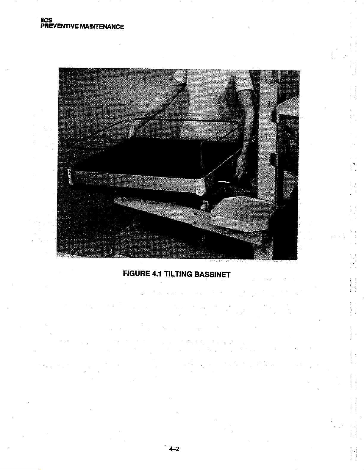
1.
TILT
THE
NOTE:
for
removing
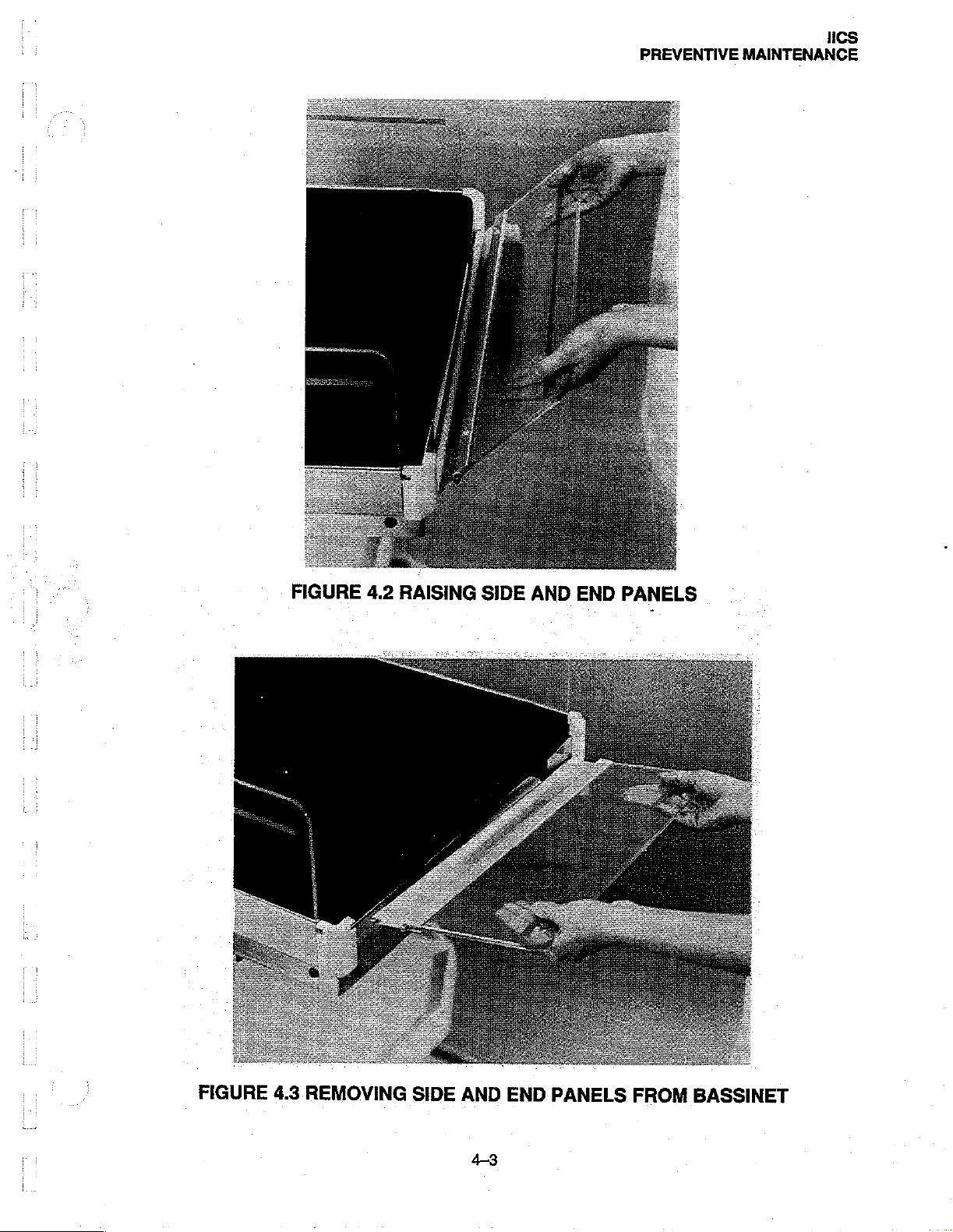
2.
RAISE
3.
REMOVE
until
it
4,
REMOVE
BASSINET
The
side,
THE
THE
snaps
THE
front,
any
or
PANEL
PANEL
free
of
MATTRESS
FOR
AND
to
and
all
of
(Figure
the
detent
CLEANING
REMOVAL
the
Fowler
back
panels
these
panels
4.2)
(Figure
4.3)
in
the
from
|
OF
position
of
is
and
swing
by
grasping
corner
the
Bassinet.
BASSINET
as
shown
the
Bassinet
the
same.
the
panel
the
mount;
slide
in
are
away
ends
the
Figure
mounted
from
of
the
panel
other
end
4.1.
identically;
the
Bassinet.
and
raising
of
the
panel
therefore,
out
the
one end
of
the
corner
procedure
of
the
panel
mount.
41
ICS
PREVENTIVE
.
MAINTENANCE
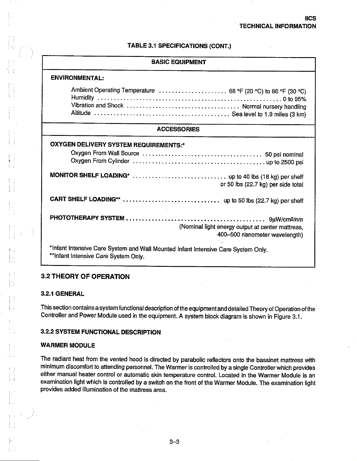
FIGURE
4.1
TILTING
BASSINET
42
PREVENTIVE
HCS
MAINTENANCE
FIGURE
4.3
REMOVING
SIDE
AND
43
END
PANELS
FROM
BASSINET
 Loading...