

Page 1
INSTALLATION INSTRUCTIONSOWNER’S GUIDE &
Sealcast
™
and Cast Resin Transducers
Models: M42, M155, M163, M172, M177, R155
IMPORTANT : Please read the instructions completely
before proceeding with the installation. These
instructions supersede any other instructions in your
instrument manual if they differ.
CAUTION : NEVER USE SOLVENTS!
Cleaners, fuel, paint, sealants, and other products may
contain strong solvents, such as acetone, which attack
many plastics greatly reducing their strength.
17-011 rev. 05 10/05
Mounting Location
Carefully study the hull to determine the best mounting location.
•Away from the propeller(s) and shaft(s), other machinery, and
other echosounders to minimize the effect of noise on the
echosounder display. The lower the noise level, the higher the
gain setting that can be used.
• On the side of the hull where the propeller(s) blades are moving
downward. The upward motion of blades generates pressure
waves and pushes bubbles up against the hull. By mounting on
the downward side, the hull shades the transducer from this
effect (see Figure 1).
• Where the transducer beam will be unobstructed by the keel or
propeller shaft(s).
• Where there is a minimum deadrise angle.
• Where there is adequate headroom inside the vessel for the
height of the stuffing tube and tightening the nuts.
• Locate the transducer about 1/3 aft LWL. Generally, this
provides the best compromise between obtaining aeration-free
water away from the bow and minimizing propeller noise (see
Figure 2).
Caution : Do not mount in an area of turbulence or bubbles:
Near water intake or discharge openings,
Behind strakes, fittings, or hull irregularities.
Record the information found on the cable tag for future reference.
Part No._________________Date___________Frequency________kHz
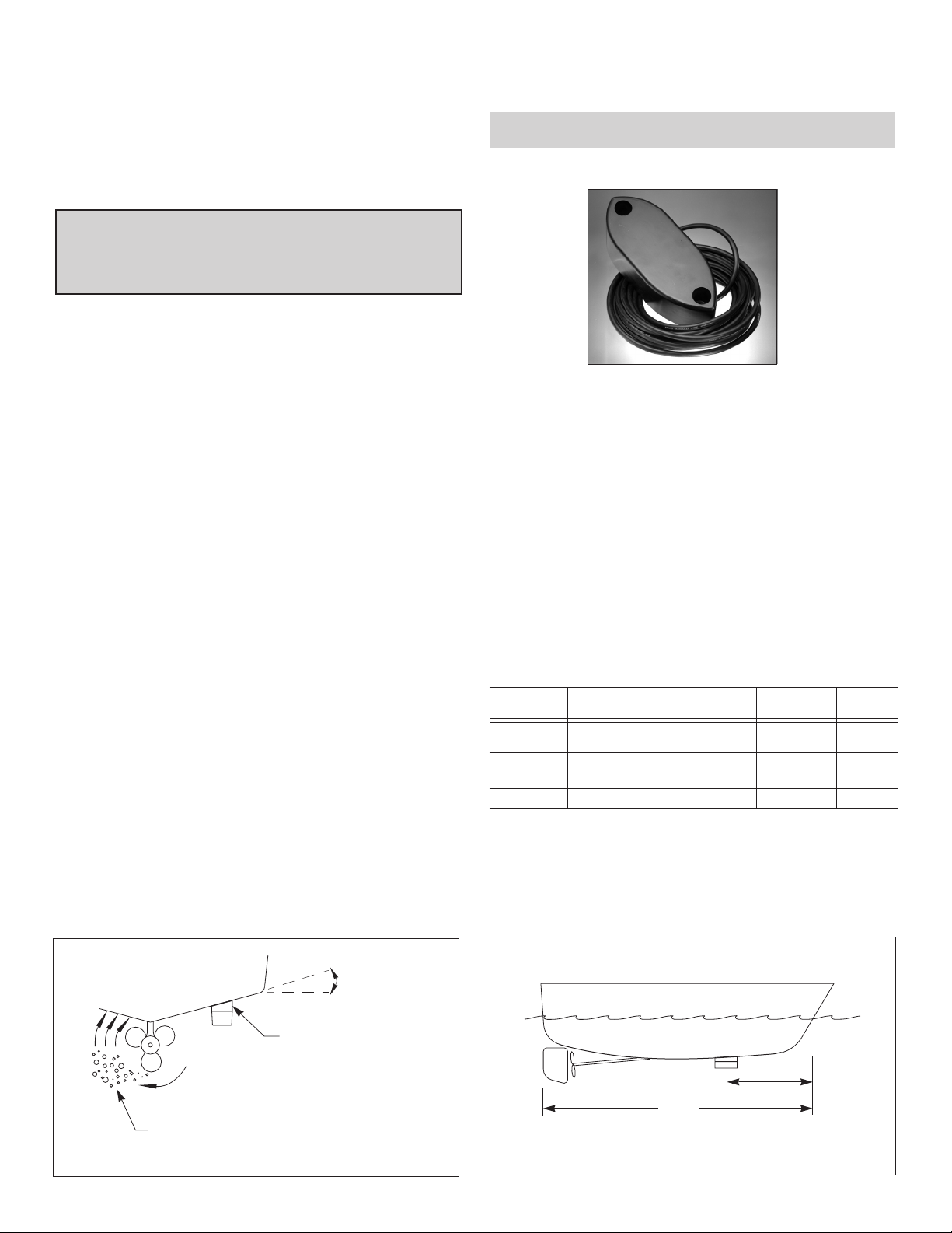
M155
Stuffing Tube
Choosing the Stuffing Tube
Warning: A stuffing tube is required for all installations.
Caution : The stuffing tube must be compatible with the hull material
The stuffing tube seals the hull forming a water-tight conduit for
the cable. Choose a stuffing tube based on the hull material and
diameter of the transducer cable. Airmar stuffing tubes are
available from your marine dealer (see table below).
Fiberglass hull —The stuffing tube
fiberglass, not in coring.
Aluminum hull —Use a stainless steel stuffing tube.
bronze stuffing tube as electrolytic corrosion will occur.
Stuffing Tube
Material
bronze
stainless steel
steel weld to steel hull up to 0.5” D 38mm (1-1/2") 33-818
a. Requires the tube to be isolated from the hull with non-electrically conductive spacers.
Hull Material Cable Diameter
fiberglass
wood
fiberglass, wood
steel, aluminum
a
Installing the Stuffing Tube
After determining the best mounting location, install the stuffing tube.
Follow the installation instructions that came with the stuffing tube.
must
be installed in solid
Never
use a
Hull Hole
Diameter
up to 0.47” D 44mm (1-3/4") 33-511-01
up to 0.47” D 26mm (1") 33-819
Airmar
Part No.
Tr ansom View
pressure waves
aeration, cavitation, and turbulence
slope of hull
deadrise angle
parallel to waterline
fairing
- corrects for the deadrise angle
of the hull, so the transducer
beams shoots straight down
- mounts the transducer deeper
in the water for clean flow
over the transducer’s face
Figure 1. Mounting location and deadrise angle
AIRMAR
®
1/3 aft
LWL
(Load Waterline Length)
AIRMAR
®
Figure 2. Mounting location on displacement hull
Page 2
▲
AIRMAR
®
cutting
cavity
guide
Figure 3. Airmar fairing
Bow
➣
arrow points
toward bow
backing block (2)
77mm (3")
deadrise shape
deadrise shape
fairing
Figure 4. Fabricating a fairing
and backing blocks
Fairing
Nearly all vessels have some deadrise angle at the transducer’s
mounting location. If the transducer is mounted directly to the hull,
the sound beam will be tilted off the vertical at the same angle as
the deadrise. If the deadrise angle at the mounting location
exceeds 10 ° a fairing is strongly recommended (see Figure 1).
•Orients the sound beam straight down by mounting the
transducer parallel to the water surface.
• Mounts the transducer deeper in the water for clean flow over
the transducer’s face.
AIRMAR Polymer Fairing
Made of a high impact polymer with an integrated cutting guide,
the Airmar fairing is easy to cut with a band saw and shape with
hand tools (see Figure 3). The fairing also has a center cavity for
the stuffing tube and cable service loop.
Model (see cab
M155, R155, M172 33-147
M177 33-145
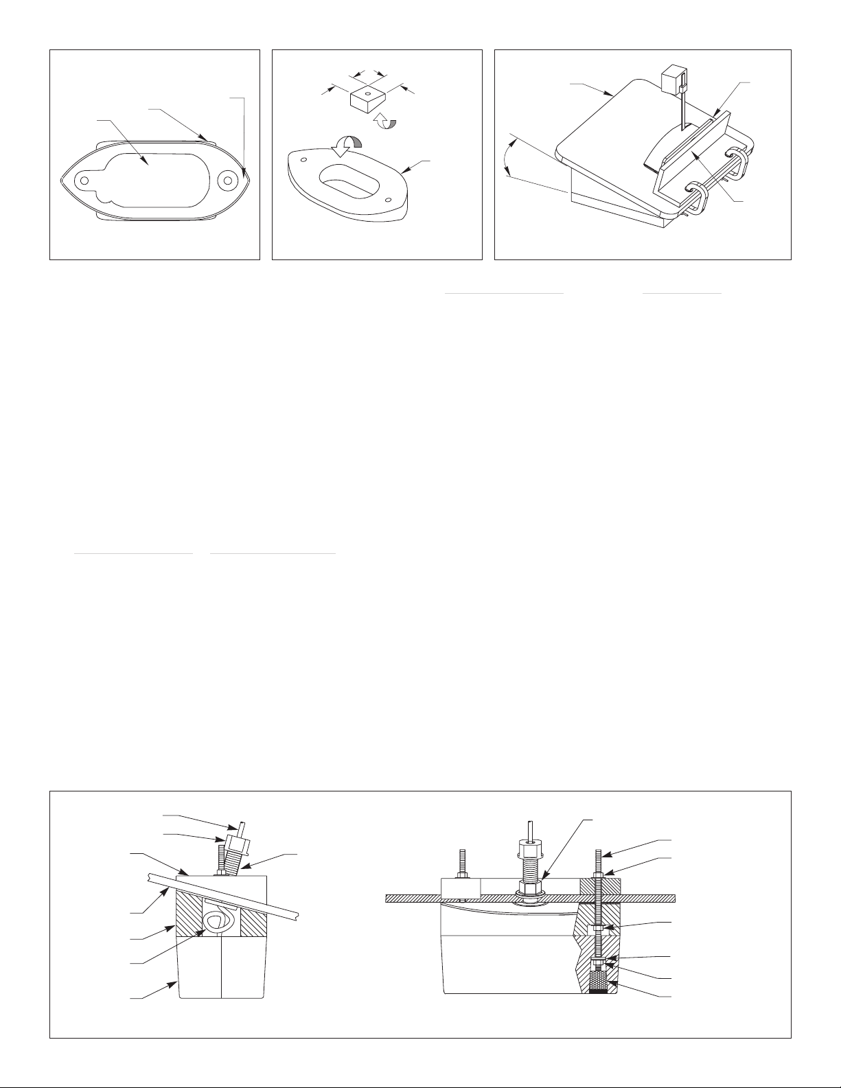
Fabricating a Fairing & Backing Blocks
A fairing is usually constructed of an oily wood such as mahogany
or teak. Shape the fairing to match the outline of the transducer
(see Figure 4). Cut a 75mm x 150mm (3" x 6") hole in the center
of the fairing for the stuffing tube and the cable service loop. Place
the transducer over the fairing and using the transducer as a
guide, drill two holes for the threaded rods.Backing blocks are
mounted inside the hull to provide a level surface for tightening the
nuts that hold the threaded rods. They are fabricated to match the
interior deadrise angle. Drill a hole through the center of each
backing block.
le tag) Airmar Fairing Part No.
➣
®
band saw
table
deadrise
angle
AIRMAR
77mm (3")
blunt
end
Bow
Figure 5. Cutting an Airmar fairing
Model (see cab
le tag) Hole Diameter
M42 13mm or 1/2"
M163 10mm or 3/8"
Cutting the Fairing
Warning : The fairing must be installed parallel to the keel to
ensure proper boat handling and water flow over the transducer.
1. The stuffing tube will be centered in the cavity of the fairing (see
Figures 3, 4 & 6). Measure the deadrise angle of the hull at the
stuffing tube using an angle finder or a digital level (see Figure 1).
2. Tilt the band saw table to the measured angle and secure the
cutting fence (see Figure 5).
Caution : The arrow will be pointing forward toward the bow
after the fairing is installed (see Figure 3).
M177 —This fairing is symmetrical.
3. Place the fairing on the table so the cutting guide rests against
the fence. The arrow will be pointing toward you for installation
on the port side and away from you for installation on the
starboard side of the boat (see Figure 5).
fairing on the band saw so the angle cut matches the intended
side of the hull and not the mirror image.
Warning : Always wear safety goggles and a dust mask.
4. Recheck steps 1 through 3; then cut the fairing.
5. Center the stuffing tube in the cavity of the fairing.
fairing is parallel to the keel (centerline). Shape the fairing to the
hull as precisely as possible with a rasp or power tool.
6. The remaining section of the fairing with the cutting guide will
be used as the backing block inside the hull. It will provide a
level surface for tightening the nuts on the threaded rods.
Be sure
to orient the
Be sure
AIRMAR
cutting
guide
fence
the
®
backing block
service loop
transducer
2
cable
compression nut
hull
fairing
cable
forward view
stuffing
tube
Figure 6. Threaded stem stuffing tube installation
Bow
➣
backing block
fairing
transducer
—stainless steel stuffing tube shown
flanged nut
or
nut & washer
threaded rod (2)
nut (2) & washer (2)
nut (2) & washer (2)
rubbery washer (2)
nut (2) & washer (2)
plug (2)
AIRMAR
®
Page 3

Installing the Fairing & Transducer
M172 —Follow separate installation instructions on page 3.
Warning: The fairing must be installed parallel to the keel to
ensure proper boat handling and water flow over the transducer.
1. Locate the hole for the forward threaded rod (see Figures 3 & 6).
Hold the fairing against the hull,
points forward toward the bow
inside the cavity. With the fairing parallel to the centerline of
the boat (keel) , use the
Drill the 11mm or 7/16" diameter hole through the hull for the
threaded rod.
2. Temporarily fasten the fairing to the hull with one of the
threaded rods. With the fairing parallel to the centerline of
the boat (keel) , use the
the 11mm or 7/16" diameter hole through the hull for the
remaining threaded rod.
3. Remove the temporary threaded rod. Clean and sand the area
around the holes, inside and outside, to ensure that the marine
sealant will adhere properly. Remove any petroleum residue with
a mild household detergent or a weak solvent such as alcohol.
Metal hull —Remove all burrs with a file and sandpaper
Welded steel stuffing tube
seal the cable inside the stuffing tube before the transducer and
fairing are attached to the hull. Follow the instructions that came
with your stuffing tube.
4. Apply a 2mm (1/16") thick layer of marine sealant to the surface
of the fairing that will contact the hull (see Figures 6 & 7).
5. Apply a 2mm (1/16") thick layer of marine sealant to each
threaded rod. The marine sealant will seal the hull and hold the
nuts securely in place. Screw a nut and slide a stainless steel
washer onto each threaded rod. Position the nuts a distance
from the rod ends equal to dimension “A”. Slide the threaded
rods through the fairing.
Do not drill the second hole at this time.
forward
aft
Note : The rods will extend above and below the fairing
6. Place the fairing against the hull, pushing the threaded rods
through the hull. With a person stationed inside the vessel,
position the backing block on the rods. Secure each rod with a
stainless steel washer and nut (see Figure 8). Tighten the nuts
with a torque wrench using a force not exceeding 7 N-m (5 ft.-lb.).
Aluminum hull —
prevent electrolytic corrosion.
Be sure
Caution : Never pull, carry, or hold the transducer by its cable as
this may sever internal connections.
7. Thread the transducer cable through the cavity in the fairing and
the stuffing tube to the inside of the hull. Apply a 2mm (1/16")
thick layer of marine sealant to the surface of the transducer that
will contact the fairing. Push the transducer onto the threaded
rods (see Figures 6 & 7).
8. Mount the transducer to the fairing by sliding a rubbery washer
and stainless steel washer onto each threaded rod and
securing them with a nut. Tighten the nuts with a torque wrench
using a force not exceeding 12 N-m (10 ft.-lb.).
Note : The rods should extend a minimum of 3 threads beyond
the nut after it is tightened. Be sure there is marine sealant on
the exposed threads.
9. Plug the mounting holes to minimize turbulence on the surface
of the transducer. Cut the foam plugs to length so that each
plug will be recessed 5mm (3/16") below the surface of the
housing. Push the foam plugs into the holes. Use marine
sealant to fill each recess
10.Remove excess sealant on the outside of the hull and the
fairing to ensure smooth water flow over the transducer.
being sure the arrow/blunt end
and the stuffing tube is centered
hole in the fairing as a guide.
hole in the fairing as a guide. Drill
with
conduit only —It is easier to
.
the rods are isolated from the hull to
FLUSH
with the transducer’s surface.
model dimension “A”
M155 28kHz 54mm (2.13")
M155 38kHz 45mm (1.75")
R155 45mm (1.75")
M177 86mm (3.38")
dimension “A”
Figure 7. Marine sealant
—detail shown
AIRMAR
marine
sealant
Sealing & Routing the Cable
To form a watertight seal inside the stuffing tube, follow the
installation instructions that came with your stuffing tube.
Route the cable to the echosounder
cable jacket when passing it through the bulkhead and other parts of
the boat. To reduce electrical interference separate the transducer
cable from other electrical wiring and the engine. Refer to your
echosounder owners manual to connect the cable to the instrument.
being careful
not to tear the
Checking for Leaks
Warning : Never install a transducer and leave the boat in the
water unchecked for several days.
When the boat is placed in the water, immediately check around
the stuffing tube and the rods that fasten the transducer to the hull
for leaks. Note that very small leaks may not be readily observed. It
is best not to leave the boat in the water unattended for more than 3
hours before checking it again. If there is a small leak, there may be
considerable bilge water accumulation after 24 hours.If a leak is
observed around the stuffing tube, tighten the compression nut
another quarter turn and see if the leakage stops. If there is a leak
around the threaded rods or the outside of the stuffing tube, repeat
the installation and sealing procedures immediately .
Maintenance & Replacement
Antifouling Paint
Surfaces exposed to salt water
paint. Use water-based antifouling paint only.
based antifouling paint, since ketones can attack many plastics
possibly damaging the transducer.
Cleaning
Aquatic growth can accumulate rapidly on the transducer’s face,
reducing its performance within weeks. Clean it using a ScotchBrite® scour pad and mild household detergent,
avoid making scratches. In severe cases, lightly wet sand the
surface with fine grade wet/dry paper.
Replacement
Contact your marine dealer or echosounder manufacturer to
obtain parts.The information needed to order a replacement Airmar
transducer is printed on the cable tag.
ordering, specify the part number, date, and frequency in kHz. For
convenient reference, record this information on the top of page one.
must
be coated with antifouling
Never
being careful
Do not
remove this tag. When
use ketone
to
®
3
Page 4

marine
sealant
®
transducer
housing
AIRMAR
Figure 8. M172 installation in resin housing
Installing the M172
M172 in Resin Housing with Fairing
1. After the stuffing tube is installed following the instructions that
came with it, apply a 2mm (1/16") thick layer of marine sealant to
each threaded rod. Secure each rod with a nut. The rods should
extend a minimum of 3 threads beyond the nut. Slide a stainless
steel washer and rubbery washer onto each rod (see Figure 8).
2. Insert the transducer into the housing and place the clamp bar
on top. Slide the threaded rods up through the housing and
clamp bar. Secure the assembly in place with a stainless steel
washer and nut. Tighten the nuts with a torque wrench using a
force not exceeding 12 N-m (10 ft.-lb.).
3. Slide the fairing onto the threaded rods. Position it against the
transducer assembly.
Caution : Never pull, carry, or hold the transducer by its cable as
this may sever internal connections.
4. Thread the transducer cable through the stuffing tube to the
inside of the hull. Allow a service loop in the cavity of the fairing
so there is no tension applied to the cable.
5. Apply a 2mm (1/16") thick layer of marine sealant to the surface
of the fairing that will contact the hull.
AIRMAR
threaded
rod (2)
nut (2) and
washer (2)
backing
block
hull
fairing
clamp
nut (2)
rubbery
washer (2),
nut (2) and
washer (2)
plug (2)
hull
tank
nut (2)
clamp bar
(shortened)
screw (2)
plate
bolt (4)
transducer
weld
Figure 9. M172 tank mount
6. Place the entire assembly against the hull, pushing the rods
through the hull. With a person stationed inside the vessel,
position the backing block on the rods. Secure each rod with a
stainless steel washer and nut. Tighten the nuts with a torque
wrench using a force not exceeding 7 N-m (5 ft.-lb.).
7. Plug the mounting holes to minimize turbulence on the surface
of the transducer.Cut the foam plugs to length so that, each
plug will be recessed 5mm (3/16") below the surface of the
housing. Push the foam plugs into the holes. Use marine
sealant to fill each recess flush with the transducer’s surface.
8. Remove excess marine sealant on the outside of the hull and
fairing to ensure smooth water flow over the transducer.
9. Follow the instructions that came with your stuffing tube to seal
the cable.
10.Check for leaks (see “Checking for Leaks” on page 3).
M172 Tank Mount
11.It is recommended that the clamp bar be shortened and redrilled to accommodate two bolts. They will secure the
transducer to threaded stand-offs that are welded to the floor of
the tank (see Figure 9). Check for leaks (see “Checking for
Leaks” on page 3).
®
®
AIRMAR
TECHNOLOGY CORPORATION
4
35 Meadowbrook Drive, Milford, New Hampshire 03055-4613, USA
■
Copyright © 2005 Airmar Technology Corp. All rights reserved.
www.airmar.com
 Loading...