

Page 1
INSTALLATION INSTRUCTIONSOWNER’S GUIDE &
In-Hull, 1kW
Transducer
Models: M260, M265LH, M265LM
U.S. Patent No. 7,369,458. UK Patent No. 2 414 077. U.S. Patent Pending
Follow the precautions below for optimal
product performance and to reduce the risk of
property damage, personal injury, and/or death.
WARNING: Always wear safety goggles and a dust
mask when installing.
CAUTION: The fiberglass hull below the transducer
17-446-01 rev.05 01/12/13
must be solid. The transducer will not transmit through
coring material such as foam or balsa wood.
CAUTION: CHIRP transducer—Do not install in the
engine compartment or other hot place. The
transducer may fail if the temperature of the liquid in
the tank exceeds 60° C (140° F).
CAUTION: CHIRP transducer—Always operate the
transducer in liquid. Operating in air will allow the
transducer to overheat resulting in failure.
CAUTION: Never pull, carry, or hold the transducer by
the cable. This may sever internal connections.
CAUTION: Never use solvents. Cleaners, fuel, sealant,
paint and other products may contain solvents that can
damage plastic parts, especially the transducer’s face.
IMPORTANT: Please read the instructions completely
before proceeding with the installation. These
instructions supersede any other instructions in your
instrument manual if they differ.
Tools & Materials
Safety goggles
Dust mask
Rope
Detergent (some installations)
Weak solvent (such as alcohol)
Disk sander (some installations)
Thin sealable plastic bag (some installations)
Cable ties (some installations)
Water-based lubricant (such as K-Y
Carpenter’s level
Pencil
Saw
Scissors
Sand paper: 80 grit
Bonding material (see www.airmar.com for additional brands):
Fiberglass resin: Bondo 401
West Marine #1937762)
or Marine-Tex epoxy putty (14 oz. pack)
or 3M™ Marine Adhesive/ Sealant 5200
Propylene glycol (non-toxic anti-freeze/coolant)
Grommet(s) (some installations)
Torque wrench with Allen-wrench adaptor (recommended)
®
jelly) (some installations)
Record the information found on the cable tag for future reference.
Part No._________________Date___________Frequency________kHz
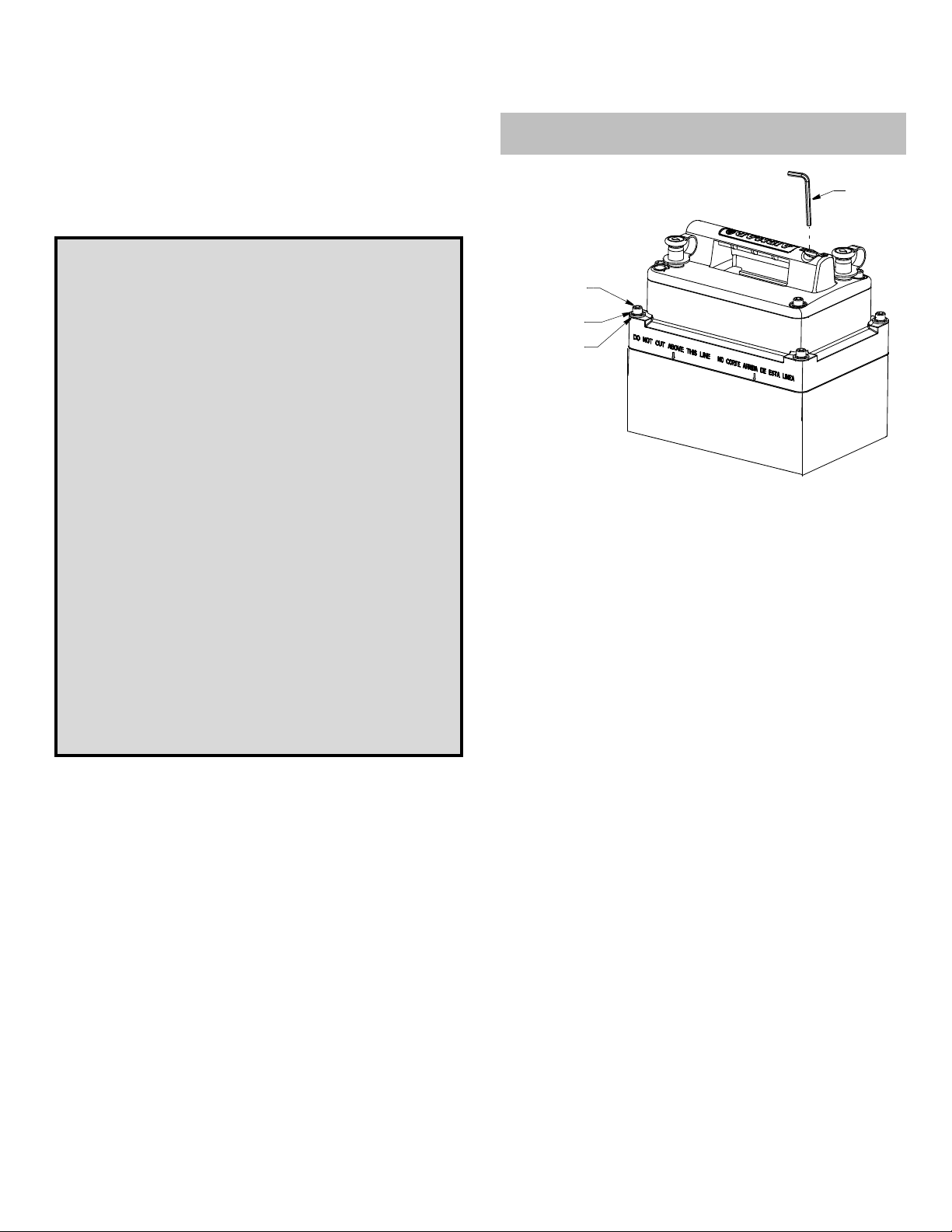
Allen
wrench
socket head
cap screw (4)
lock washer (4)
flat washer (4)
Figure 1. M260
upper section of tank
lower section of tank
Applications
• Fiberglass hulls only
• Recommended for high-speed boats
• Accommodates a deadrise angle up to 30° with the longest side
of the tank installed parallel to the centerline (keel) of the hull.
Mounting Location
About Fiberglass Hulls
Since the hull absorbs acoustic energy, transmitting through the
hull reduces the transducer’s performance. Fiberglass hulls are
often cored in places for added strength or to reduce weight. These
cored areas contain balsa wood or structural foam which are poor
sound conductors. Do not locate the transducer over coring.
Choose a Location
• Where the fiberglass is solid (no air bubbles are trapped in the
fiberglass resin) and where no coring, flotation material, or dead
air space is sandwiched between the inside skin and outer skin
of the hull.
• Where the hull below the transducer will be in contact with the
water at all times.
• Where the water flowing under the hull is smoothest with a
minimum of bubbles and turbulence (especially at high speeds).
Do not mount the transducer near water intake or discharge
openings; or behind strakes, fittings, or hull irregularities.
• Where the transducer beam will not be blocked by the keel or
propeller shaft(s).
• Away from interference caused by power and radiation sources
such as: the propeller(s) and shaft(s), other machinery, other
echosounders, and other cables. The lower the noise level, the
higher the echosounder gain setting that can be used.
• Where the deadrise angle of the hull does not exceed 30°.
• Where there is space inside the vessel for the size of the tank
and removing the transducer.
• CHIRP transducer—Mount in a cool well-ventilated area away
from the engine to avoid overheating the liquid inside the tank.
Page 2
displacement hull
pressure waves
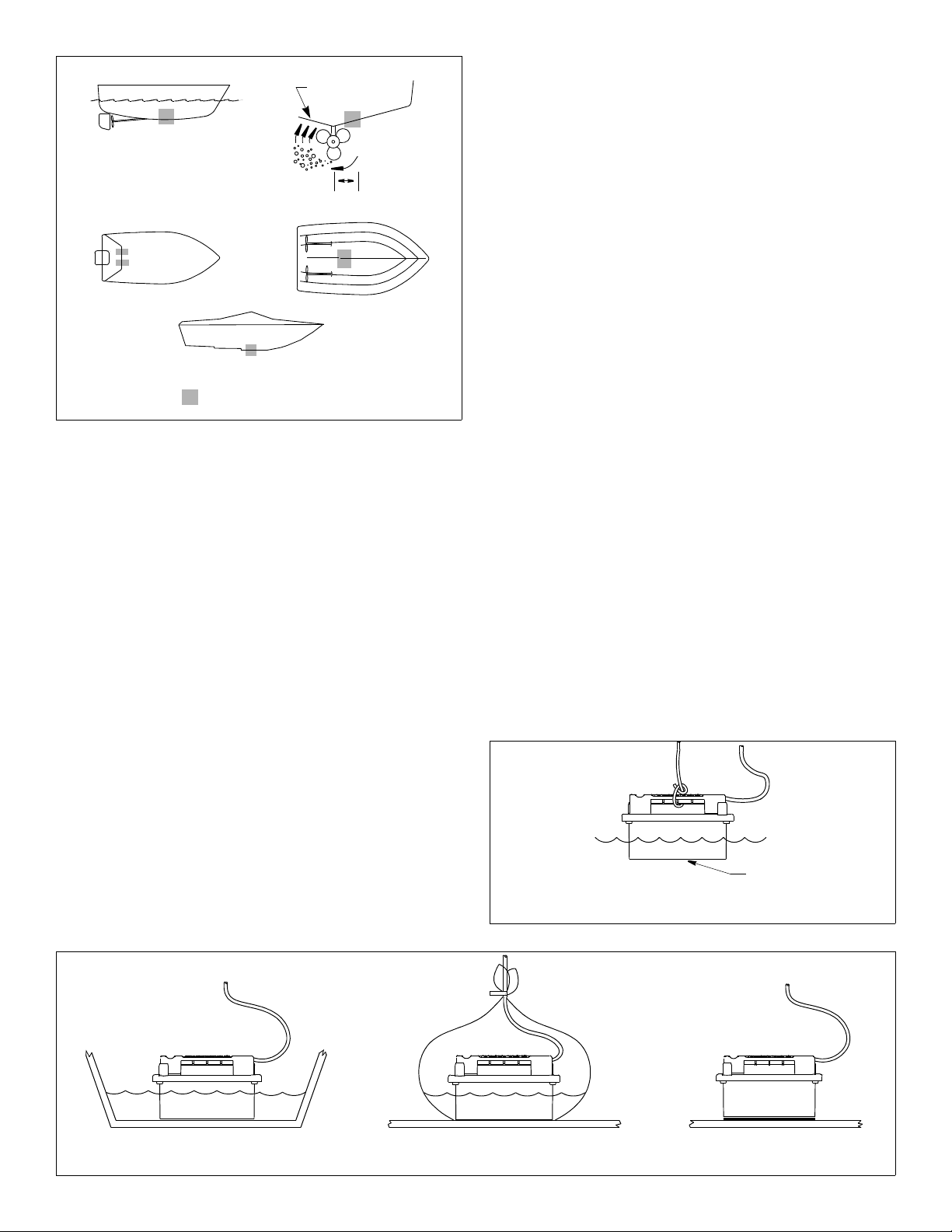
Testing the Location
While the boat is at the same site (depth of water), test the
transducer inside the hull at the mounting location. Use one of the
test methods below:
150- 300mm
(6-12")
planing hulls
outboard and I/O
Figure 2.
stepped hull
Best location for the transducer
Copyright © 2006 Airmar Technolog y Corp.
inboard
Boat Types (see Figure 2)
• Displacement hull powerboats—Locate amidships near the
centerline. The starboard side of the hull where the propeller
blades are moving downward is preferred.
• Planing hull powerboats—Mount well aft, on or near the
centerline, and well inboard of the first set of lifting strakes to
ensure that the transducer will be in contact with the water at
high speeds. The starboard side of the hull where the propeller
blades are moving downward is preferred.
Outboard and I/O—Mount just forward of the engine(s).
Inboard—Mount well ahead of the propeller(s) and shaft(s).
Stepped hull—Mount just ahead of the first step.
Testing the Selected Mounting Location
Establishing a Performance Baseline
The results of this test are used as a basis of comparison to
determine the best in-hull location for the transducer.
1. Take the boat to the maximum depth in which you will be
operating the echosounder. If deep water is not available, find a
location with at least 30m (100').
2. Connect the transducer to the echosounder.
3. Tie a rope securely around the handle of the transducer (see
Figure 3). Lower it over the side of the boat until the active face
is fully submerged and parallel to the water surface.
4. Observe the echosounder’s performance and the depth reading.
A.If the transducer will be located near the stern and the boat has
a minimum deadrise angle—Clean away any build-up of dirt and/
or grease using detergent or a weak solvent such as alcohol. Place
the transducer against the hull and flood the area with bilge water
to cover the surface where they touch (see Figure 4-A).
B.For a moderate deadrise angle—If the hull surface is not
smooth, grind it with a disc sander. Place the transducer inside
a thin plastic bag. Partially fill the bag with water and close it
tightly with a cable tie. Wet the surface of the hull and press the
active face of the transducer against it through the bag (see
Figure 4-B).
C.For any location—If the hull surface is not smooth, grind it with a
disc sander. Coat the active face of the transducer with a waterbased lubricant (such as K-Y
®
jelly). With a twisting motion, press
the face firmly against the hull (see Figure 4-C). After testing,
wipe away all traces of the lubricant from the transducer’s face.
Observe the echosounder’s performance and compare it to the
baseline. Look for a stable depth reading that is similar to the
baseline. Compare the thickness and intensity of the bottom trace.
If the performance is close to the baseline, this is a good mounting
location. Remember, some energy is lost transmitting through the
hull. If the test reading differs markedly from the baseline, you will
need to find another location to install the transducer.
NOTE: If there is no reading or it is erratic, the transducer may be
positioned over coring which is absorbing the acoustic energy.
Choose another location. If no other location is available, check
with the boat manufacturer to be certain coring is present.
active face
Figure 3. Establishing a performance baseline
Copyright © 2006 - 2011 Airmar Tech nology Corp.
AB C
Figure 4. Testing the transducer at the selected location
Copyright © 2006 Airmar Technology Corp.
2
Page 3

Installation
Marking & Cutting
CAUTION: For optimal performance, the transducer must be
installed so the beam will be aimed straight down. This is accomplished by cutting the tank to match the deadrise angle of the hull.
Draw a level line
starting at the
lower corner.
carpenter’s
level
CAUTION: Do not mark or cut the tank in the space labeled
“Do not cut above this line.”
1. The tank can be disassembled for installation in tight places.
Do not disassemble the tank unless it is necessary. If the tank
will be installed as one unit, lightly tighten the socket-head cap
screws that hold the two sections of the tank together with a
force not exceeding 50 in.-lb. (see Figure 1). Use the Allen
wrench supplied. Do not over tighten. (To remove the Allen
wrench from the handle of the transducer, use a blade
screwdriver. After use, replace the Allen wrench in the recess.)
2. When you are satisfied that the selected mounting location is
optimal, place the tank up-side-down on the hull (see Figure 5).
NOTE: The tank can be placed with either a short side or a long
side parallel to the centerline of the boat.
3. Holding a carpenter’s level even with the lower corner of one of
the sides to be cut, draw a level line on the tank. Repeat this
process on the opposite side of the tank. Connect the two lines
to form the SHORTEST side of the tank. Be sure the lines are
level, as they will be the cutting guidelines.
4. Before cutting the tank, be sure the TALLEST side will be
closest to the centerline (keel) of the boat after the tank is
installed. And be sure to observe the “Do not cut above this
line.” Using a saw, cut the three sides of the tank along the
guidelines drawn. It may be necessary to further shape the tank
to the hull to ensure a liquid-tight bond.
5. The tank is provided with a cork liner to reduce sound echoes.
After the tank has been cut, wrap the cork liner around the
inside of the tank (see Figure 6). Butt the sides of the liner along
the center of the tallest side. Push the cork liner up against the
top edge on the inside of the tank. Trace the bottom edge of the
tank onto the liner.
NOTE: There may be a gap between the butted edges which
will not affect performance.
6. Remove the cork liner from the tank. Use scissors to cut the
liner along the line drawn.
Do not mark
below this line.
top
of tank
hull
Figure 5. Marking the cutting guidelines (30° deadrise angle shown)
Copyright © 2006 - 2011 Airmar Technol ogy Corp.
Bonding the Tank
CAUTION: The tank must be liquid-tight. To ensure a tight bond,
the hull surface under and around the tank must be smooth, free
of paint or any other finish, clean, and dry.
1. To ensure a tight bond, remove any paint or other hull finish. If the
surface is rough, use a disk sander to smooth an area slightly larger
than the tank. Clean any dust, grease, or oil from the hull surface
with a weak solvent, such as alcohol. Dry the effected area.
2. Use 80 grit sand paper to sand the outside and inside of the
tank up 50mm (2") above the bottom edge. Remove the dust
with a weak solvent, such as alcohol. Dry the effected area.
3. Use an approved bonding material (see “Tools & Materials” on
page 1). Glass the tank to the hull with fiberglass resin, using
standard fiberglass technique. Alternatively, apply a generous
bead of marine putty/ sealant to the bottom edge of the tank
following the manufacturer’s instructions (see Figure 7). Press
the tank firmly in place. Apply a second bead around the inside of
the tank. And apply a third bead around the outside of the tank.
4. Allow the bonding material to cure. The seal must be liquid-tight.
5. If the tank is being installed in two parts, reattach the two
sections now (see Figure 1). Be sure the O-ring gasket is in place
around the lip and lubricated. Screw the two sections together
using the socket-head cap screws, lock washers, and flat
washers supplied. Use the Allen wrench to tighten the screws
with a force not exceeding 50 in.-lb. Do not over tighten.
trace bottom
edge of tank
onto cork liner
Figure 6. Fitting the cork liner (30° angle shown)
Copyright © 2006 - 2011 Airmar Tech nology Corp.
possible
gap
after bonding
material cures,
insert cork liner
Figure 7. Bonding the tank
Copyright © 2006 - 2011 Airmar Techn ology Corp.
hull
fiberglass
in place
or apply
three beads
of marine
putty/ sealant
3
Page 4

Installing the Transducer
CAUTION: Do not use sealant or adhesive on the gasket. To do
so may break the tank when the transducer is removed.
CAUTION: Do not over-tighten the bolts to avoid cracking the tank.
1. After the bonding material has cured, insert the cork liner into the
tank (see Figure 7). Butt the edges along the center of the tallest
side. Note, there may be a gap, but this will not affect performance.
2. Following the manufacturer’s directions for use, pour propylene
glycol into the tank until it covers the exposed hull.
3. Before installing the transducer, wipe it clean of any lubricant
that was used in testing the mounting location. Check that the
O-ring gasket is in the groove around the lip of the transducer.
4. Grasp the transducer by the handle and lower it into the tank
(see Figure 8). There is no fore or aft to the transducer; it fits
either way.
M265LH/LM—Be careful lowering the transducer. The metal
plate on each side make a snug fit against the tank opening.
5. Attach the transducer to the tank. Use the four socket-head cap
screws, four lock washers, and four flat washers supplied.
Lightly tighten with the Allen wrench supplied, using a force not
exceeding 35 in.-lb. Do not over tighten. (Use a blade
screwdriver to remove the Allen wrench from the recess in the
handle of the transducer. Replace the Allen wrench after use.)
6. Top-off the propylene glycol in the tank. However, allow a small
air space to accommodate expansion with temperature
changes. Using the funnel supplied, pour the fill-liquid through
one of the fill/vent holes until the tank is full (see Figure 9). The
second hole will act as a vent. (Alternately, the tank can be filled
using standard diameter tubing secured with a band clamp.)
Attach the stoppers supplied and plug both fill/vent holes. To
ease sliding, lubricate the stoppers with the fill liquid. Tie the
funnel to the handle to keep it near-at-hand.
Cable Routing & Connecting
CAUTION: If the transducer came with a connector, do not
remove it to ease cable routing. If the cable must be cut and
spliced, use Airmar’s splash-proof Junction Box No. 33-035 and
follow the instructions provided. Removing the water-proof
connector or cutting the cable, except when using water-tight
junction box, will void the transducer warranty.
stopper (2)
socket head
cap screw (4)
lock washer (4)
flat washer (4)
transducer
with O-ring gasket
in place under lip
upper section
of tank
lower section
of tank
Figure 8. Installing the transducer in the tank
Copyright © 2006 - 2011 Airmar Techno logy Corp.
funnel
transducer
propylene glycol
(non-toxic antifreeze/ coolant)
cork liner
(M260 shown)
stopper (2)
fill/vent hole (2)
hull
Allen
wrench
1. Route the cable to the echosounder being careful not to tear the
cable jacket when passing it through the bulkhead(s) and other
parts of the boat. Use grommets to prevent chafing. To reduce
electrical interference, separate the transducer cable from other
electrical wiring and the engine(s). Coil any excess cable and
secure it in place with cable ties to prevent damage.
2. Refer to your echosounder owner’s manual to connect the
transducer to the instrument.
Replacement Transducer & Parts
The information needed to order a replacement Airmar transducer
is printed on the cable tag. Do not remove this tag. When ordering,
specify the part number, date, and frequency in kHz. For convenient reference, record this information at the top of page one.
®
AIRMAR
TECHNOLOGY CORPORATION
4
35 Meadowbrook Drive, Milford, New Hampshire 03055-4613, USA
•
Copyright © 2006 - 2013 Airmar Technology Corp. All rights reserved.
Figure 9. Cross section of installed transducer
Copyright © 2006 - 2007 Airmar Tech nology Corp.
Lost, broken, or worn parts should be replaced immediately.
In-Hull Mounting Kit 33-539-01
Obtain parts from your instrument manufacturer or marine dealer.
Gemeco Tel: 803-693-0777
(USA) Fax: 803-693-0477
email: sales@gemeco.com
Airmar EMEA Tel: +33.(0)2.23.52.06.48
(Europe, Middle East, Africa) Fax: +33.(0)2.23.52.06.49
email: sales@airmar-emea.com
www.airmar.com
 Loading...