

Page 1

dB PLUS II
Acoustic Deterrent System
U.S. Patent No. 5,610,876
Norwegian Patent No. 304001
European Patent No. EP 0706 317 B1
AIRMAR
TECHNOLOGY CORPORATION
OWNER ’ S
MANUAL
35 Meadowbrook Drive, Milford, New Hampshire 03055-4613, USA
Tel: 603.673.9570
■
Fax: 603.673.4624
■
E-mail: sales@airmar.com
17-5000 rev . 4 06/02
Page 2

Table of Contents
Section Page
Airmar Technology Corporation .................................................. 1
dB Plus II
Installation ................................................................................... 2
Operation ..................................................................................... 5
Maintenance ................................................................................ 6
Safety .......................................................................................... 7
Troubleshooting Problems .......................................................... 7
Specifications .............................................................................. 8
Repair .......................................................................................... 8
Options, Parts and Accessories .................................................. 9
Airmar Limited Warranty ............................................................ 10
dB Plus II
System Overview .................................................. 1
System Layout ......................................................................... 2
Projector Installation ............................................................... 3
Transmitter Installation ........................................................... 3
Power Supply System ............................................................. 4
Battery Charging ..................................................................... 4
Battery Enclosure .................................................................... 4
Power-up ................................................................................. 5
Normal Mode .......................................................................... 5
Power Save Mode ................................................................... 5
Shutdown Mode ...................................................................... 6
Fuse Protection ........................................................................ 6
Batteries .................................................................................. 6
Projectors ................................................................................ 6
Transmitter Inoperative ........................................................... 7
Projector(s) Not Pulsing .......................................................... 7
Reduced Sound Output. .......................................................... 7
Cable ....................................................................................... 8
Transmitter .............................................................................. 8
External Triggering Capability ............................................... 9
Parts and Accessories .............................................................. 9
Limited Warranty .................................................................. 10
Warranty Return Procedure .................................................. 10
Limitation of Remedies ......................................................... 10
Registration Form ................................................ 11
Page 3

AIRMAR
To our customers:
Thank you for purchasing Airmar Technology Corporation’s
Since its founding in 1981, Airmar has been a leader in product innovation and technical excellence. Our
position as a world-class manufacturer is evidenced by the many U.S. and foreign patents we hold.
You have chosen a product with a proven performance record of reliability and quality, and we are
confident you will be satisfied with it. This manual provides important information regarding its operation
and maintenance. To achieve optimal performance, it is important that you familiarize yourself with its
content.
Installation of your
determine the best layout of equipment based on a site assessment. The proper placement of the sound
projectors is necessary to ensure maximum protection from predators.
A reliable power source is of crucial importance to the effectiveness of the product, especially when it must
be installed away from shore power. Care should be taken to ensure proper installation and maintenance
of your power supply in accordance with the manufacturer’s instructions.
Airmar has made product safety a priority in the design of the
using the safety features, should ensure the protection of both humans and marine mammals.
Airmar Technology Corporation backs the
defects in workmanship. However, we cannot guarantee that the system will completely eliminate attacks,
such as those from hearing impaired seals. Hearing loss, occurring in a small portion of marine mammals,
can be attributed to interactions with fisheries using “seal bombs” and parasites known to effect the hearing
of older marine mammals. Airmar recommends using the
predator control methods.
Welcome to the Airmar family of satisfied customers!
dB PLUS II
system should be performed by a factory authorized technician who will
Technology Corporation
dB PLUS II
dB PLUS II
dB PLUS II
equipment with a one year warranty against
dB PLUS II
system in conjunction with other
Acoustic Deterrent System.
system. Proper operation,
dB Plus II
dB PLUS II
The
projectors
that cause significant discomfort to seals in the guarded area. However, these pulses have no known effect
on fish since the system’s frequency of operation is well above their hearing range.
The rugged
environment. This feature-rich system includes low-power warning alarms as well as an array of safety
enhancements.
To protect both divers and marine mammals, it is equipped with a unique Soft-start feature which allows
time to clear the area before reaching full sound output. As further protection for divers, the transmitter
power switch is designed to be locked in the “OFF” position to prevent accidental activation, and the highvisibility cover can be drawn over the transmitter box to signify a diver’s presence in the water.
Development of the
over an extended period of time. It is the most advanced system available today.
1
, operating from one, four circuit, DC powered transmitter, provide high intensity acoustic pulses
1.Projector and transducer are synonymous terms in this document.
Acoustic Deterrent System provides up to 3,000 square meters of protection. Four
dB PLUS II
dB PLUS II
equipment is designed to withstand the harsh conditions of the marine
Acoustic Deterrent System has involved extensive field tests conducted
System Overview
1
Page 4
Installation
After the installation of your
dB Plus II
system by a trained authorized technician, please familiarize
yourself with the following principles of installation, operation, and maintenance. This system has been
custom engineered and carefully installed at your facility. Should it be necessary to move equipment,
including relocating any of the projectors, it is recommended that the move be done by an authorized
technician for best results.
System Layout
At fish farms with square pens, Airmar recommends placing the batteries, charging devices, and
transmitter in the center of the set of pens thus allowing the projectors to be located close to the outer
corners (see Figure 1). However, if a sheltered location is available for the batteries, charging devices, and
transmitter, it should be used.
projector
pens
12m
(40')
transmitter
projector
30m
(100')
projector
60m (200')
battery bank (can be connected to alternative charging sources
such as: solar panels, wind generator, AC mains or portable generator)
projector
Figure 1. Recommended system layout for typical square pen configuration
(
The
dB Plus II
Layout will vary with different pen styles
system is designed to emit high intensity acoustic pulses from each of its four underwater
)
projectors resulting in significant discomfort to most seals. Sound pressure drops dramatically with
increased distance from the projector, so proper projector layout is
Since the placement of the projectors is the key to the success of the
imperative
dB Plus II
.
system, they must be
positioned so that the sound patterns overlap. The closer the spacing between the projectors, the higher
the intensity of the sound field, and therefore the greater the protection from predators. Using the 60 m
(200') long projector cables provided, will result in the maximum recommended spacing between
projectors at a fish farm with the above pen layout. For protection from seals, the distance between
projectors should never exceed 60m (200').
2
Page 5

The effective range of the projectors is reduced by underwater obstructions such as fouled nets or the
biomass of a school of fish. Therefore, it is necessary to completely surround the entire pen system and, in
effect, create an acoustic barrier around the outer perimeter (see Figure 2). The range of each projector
limits the coverage of a complete 4 projector system to an area not exceeding 3,000 square meters
(33,000 sq. ft.).
100 m (330')
typical radius
40 m (133')
projector 1
projector 4
60m (200')
sound pattern
around pens
projector 2
30 m (100')
projector 3
Figure 2. Projector coverage
Projector Installation
The standard
dB Plus II
system has four underwater sound projectors. Each projector has 60m (200') of
high visibility, abrasion resistant cable with a corrosion resistant, weatherproof connector. It should be
noted that the projector connectors and the power supply connectors are of reverse gender to prevent
incorrect installation. The projectors are positioned at the outer edge of the pen walkways but not in the
path of boat traffic and propellers. If the transmitter has been placed away from the center of the
installation, it may have been necessary to add extension cables to the projector cables. Airmar’s unique
design allows adding extensions with very little loss of sound output.
Whenever possible, projector cables should be laid underneath walkways. Areas prone to moving and
swaying, such as gangplanks, should be avoided, as they could chafe or cut the cable.
Each projector is equipped with an eyelet to allow it to be suspended from a line approximately 1m (3')
below the bottom of the pen. Do not suspend a projector by its power cable since this may sever internal
connections. Below the waterline, the cable must be tie-wrapped to the supporting line and free of any
slack or loops. Each projector should be suspended at the outer most edge of the walkway in order to avoid
fouling with other lines or netting. Never suspend a projector between or inside pens.
Transmitter Installation
The transmitter must be mounted at least 1m (3') above any decking and, preferably, protected from the
rain. Placing it directly under solar panels is ideal. Although the transmitter is waterproof, this added
protection will prolong its life.
WARNING : Under no circumstances, should unauthorized personnel remove the transmitter cover. Doing
so may result in electrical shock. Unauthorized removal of the transmitter cover breaks the factory seal and
voids the warranty.
3
Page 6

4
•
Power Supply System
dB Plus II
The
system requires 24VDC, supplied by lead acid batteries, to provide adequate power
surge levels during sound transmission and a temporary reserve of power for times when the batteries
cannot be recharged. Power inverters are unable to meet this requirement and are not recommended.
• Shore Power —At locations where shore power is available, AC mains, two 12V batteries and a
battery charger(s) is advised.
• Batteries —At sites where shore power is not available, a system of four 6V deep cycle batteries is
recommended (see Figure 3). Four 6V batteries connected in series provides much more reserve
capacity than two 12V batteries. Deep cycle batteries are necessary because they can withstand
the many charge and discharge cycles which occur when operating the
dB Plus II
system.
Consult your power supply manual for proper installation and maintenance of the power supply
equipment.
power cable
# 22-242
black
red
yellow
+
6V
+
6V
+
6V
+
6V
external
“Insufficient Power”
alarm
alarm cable
# 22-243
Note: 12V batteries are
hooked up in series
(ref. negative-to-positive)
in same manner as shown.
Figure 3. Power supply cable hookup
The condition of the batteries must be checked daily, regardless of the type of charging system used. The
voltage level must never drop below 24V, and electrolyte levels must be maintained in accordance with the
manufacturer’s instructions. Terminal connections must be kept tight and free of corrosion.
Battery Charging
Solar panels —Depending on the climate, a four module regulated solar panel array may be
adequate.
• Wind generators —In windy locations, regulated 24V wind generators offer an alternative means
of charging the batteries.
• Solar and wind —Weather conditions effect the performance of both solar panels and wind
generators. A charging system that combines both may provide a reliable charging source since
one of these conditions is present on most days.
• Portable generator —Use of an engine powered generator with a battery charger is much less
desirable. Manual charging must be done often enough to keep the batteries above 24V. However,
a portable generator could be used as a backup to solar or wind systems.
Any charging method may have difficulty meeting the power demand. Two sets of batteries that can be
rotated is recommended. While one set is in use, the alternate batteries can be fully charged.
Battery Enclosure
The batteries should be protected in a weatherproof structure. A wooden enclosure with venting and
drainage holes is very effective, causing less condensation than one made of plastic or fiberglass. In
locations where the temperature drops below freezing, rigid foam insulation on the inside is highly
recommended.
Page 7

Operation
Power-up
Before activating the system, scan the area around the pens for the presence of divers in the water. When
the area is clear of divers, turn the power switch to the “ON” position. Note that the projectors will start
transmitting at 20% of power and take approximately 70 seconds to reach 100% power. This unique
Soft-start
the projectors thus avoiding the possibility of hearing damage.
safety feature allows both divers and marine mammals time to swim a safe distance away from
WARNING : Before a diver enters the water within 150 m (500') of a
dB Plus II
system, always turn the
power switch to “OFF” and secure it in the “OFF” position with the locking pin attached to the diver’s
cover (see Figure 4). In addition, the high visibility diver’s cover must be securely fastened over the
transmitter , signaling the presence of a diver in the water. The pin and cover shall remain in place until the
area is clear of divers.
COVER
PROJECTOR PROJECTOR PROJECTOR PROJECTOR
SERIAL No.
BREATHER
ON/OFF SWITCH
FUSE
POWER CABLEI/O PORT
locking pin
(from diver’s cover)
Figure 4. Bottom view of transmitter
Normal Mode
The transmitter operates in the
normal mode
when the battery voltage is above 22VDC. It pulses each
projector sequentially for 2.5 seconds with a 2 second off period between transmissions. The total cycle
takes 18 seconds for all four projectors to transmit. The green light on the front panel of the transmitter
indicates
normal mode
when it is illuminated (see Figure 5).
BATTERY STATUS ALERT
BATTERIES
OK
NORMAL
OPERATION
CHARGE
BATTERIES
Yellow RedGreen
POWER
SAVE
MODE
Figure 5. Transmitter panel
Power Save Mode
When the battery voltage drops below 22VDC, the transmitter will automatically switch to the
mode
. This extends the off period between projector pulses to 6.5 seconds. Power consumption is cut by
50% while maintaining close to full sound output from the projectors. The total cycle time for all four
projectors to transmit extends to 36 seconds. When the yellow and red lights alternately illuminate on the
transmitter and the “Insufficient Power” alarm sounds, the
power save mode
batteries need recharging (see Figure 5).
Caution: Do not run the system in the power save mode for an extended period of time. This will result in
less than optimal protection from predators. This feature is designed to allow for temporary coverage until
the batteries are recharged.
INSUFFICIENT
POWER
TRANSMITTER
OFF
power save
is active indicating that the
5
Page 8

Shutdown Mode
Whenever the battery voltage drops below 20VDC, the transmitter will automatically switch to the
shutdown
battery voltage is below the level needed to power the transmitter (see Figure 5). When in the
mode, recharge the batteries as soon as possible to minimize exposure to marine mammal attacks.
mode. The red light on the front panel will flash to signal that the transmitter is off and that the
shutdown
Caution: The importance of properly maintaining and charging the batteries cannot be stressed enough.
The
dB Plus II
system will not operate as designed unless the power supply is adequate. It is highly
recommended that you develop a program of daily battery monitoring and maintenance.
Fuse Protection
The dB Plus II transmitter is protected by a 8 amp AG fuse. If the power cable leads are mistakenly
reversed or the transmitter is inoperative, check for a blown fuse. The fuse is located in a drip-proof holder
on the bottom panel of the transmitter (see Figure 4).
Maintenance
Batteries
The condition of the batteries must be monitored daily. The voltage level should not drop below
24VDC and electrolyte levels must be maintained in accordance with the manufacturer’s instructions. Keep
battery terminal connections tight and free of corrosion.
Projectors
To maintain the projectors, they must be removed from the water every month and inspected for marine
growth, chaffing of the cable and wear of the support line. Any growth on the projector’s acoustic window
will block the sound generated severely reducing its effectiveness (see Figure 6).
acoustic window
Figure 6. Projector
Caution: Always switch the transmitter to “OFF” before removing a projector from the water. The projector
is designed to transmit in water only; transmitting in air may cause damage.
To clean a projector, gently scrape growth from its surface using a stiff brush or putty knife. Remove any
remaining growth with a “scotch pad” and water. Never use solvents. Strong solvents, such as acetone,
attack many polymers and dramatically reduce their strength leading to internal leaks and projector failure.
Clean with a soft cloth and mild household detergent.
6
Page 9

Safety
Always comply with the safety precautions. The following warnings are posted on the front panel of the
transmitter.
DANGER: Temporary or permanent hearing loss may result from
underwater exposure to high intensity sound generated by this
equipment. This transmitter’s “ON-OFF” switch must be locked in
the “OFF” position whenever a person is underwater and within
150 meters (500') of a transducer.
NOTICE TO DIVERS: This transmitter’s “ON-OFF” switch must
be locked in the “OFF” position and the diver’s safety cover put in
place over the transmitter box before entering the water. If the
system is switched on accidentally, immediately surface at the
normal ascent rate.
Troubleshooting Problems
WARNING: Always lock the system in the “OFF” position before troubleshooting to avoid electrical shock
and damage to the projector(s).
Transmitter Inoperative
• Check the power supply voltage; batteries must be charged to at least 20V. Recharge the
batteries.
• Check battery terminals for corrosion. Clean the terminals if necessary.
• Check for loose or corroded power cable ends at the batteries. Clean or tighten the cable ends.
• Check for a blown transmitter fuse. Replace the blown fuse with a new 8A fuse (see Figure 4).
• Check for a loose or disconnected power cable connector. Secure the connector.
WARNING: Under no circumstances should unauthorized personnel remove the transmitter cover. Doing
so may result in electrical shock. Unauthorized removal of the transmitter cover breaks the factory seal and
voids the warranty.
Projector(s) Not Pulsing
• Check for loose or disconnected projector connectors. Secure the connector.
• Check the inoperative projector(s) cable(s) for cuts or kinks. Have damaged cable(s) repaired by a
factory trained technician or use the Airmar Splice Kit #33-045.
Reduced Sound Output.
• Check the power supply voltage; batteries must be charged to at least 20V. Recharge the
batteries.
• Check each projector for fouling. Clean the projector’s acoustic window (see Maintenance,
page 6).
• Check for underwater obstructions that might be blocking the projector(s). Remove the
obstructions or reposition the projector(s).
7
Page 10

Specifications
•Coverage for aquaculture application: up to 3,000 square meters.
(This may vary according to location, target species, and pen configuration.)
• Standard cable length: 60m (200')
• Projector transmit source level: 198dB re 1 micropascal at 1m RMS
• Projector impedance: 100 ohms
•Transmitter: 4 channels with individual fuses
•Transmitter pulse power: 1.8kW RMS per channel
• Supply voltage:
Nominal 24 VDC
Normal mode
Power Save mode
Shutdown mode
•Power consumption: 1.7 A equivalent continuous current draw in
0.9 A in
• Soft-start: 70 seconds to go from 20% to full power
•Audible “Insufficient Power” alarm: 97dB
Note: Design and specifications are subject to change without notice.
22 VDC minimum - 30 VDC maximum
20 VDC minimum - 22 VDC maximum
0 VDC minimum - 20 VDC maximum
Power Save mode
(factory preset to use 50% less power)
Normal mode
Repair
Cable
Repairs to cut or damaged cables can be made using an Airmar Splice Kit #33-045, which includes simple
to follow instructions. This kit can be obtained through your local distributor.
Transmitter
All transmitter repairs must be performed by factory trained specialists. If you experience a problem with
the dB Plus II transmitter or have questions about its operation, please call your local distributor or
Airmar Technology Corp. at (603) 673-9570. Please have the transmitter serial number (located on the
bottom of the transmitter) available at the time of the call.
8
Page 11

Options, Parts, and Accessories
External Triggering Capability
The transmitter has a connector (I/O) port for a remote switch that can be activated by a mammal detection
device or a pen monitoring system (see Figure 2). Remote activation makes it possible to transmit only
when marine mammals are detected.
Parts and Accessories
Description
Power cable 22-242
Alarm cable 22-243
Alarm and cable assembly 20-151
“Insufficient Power” alarm 07-182
Projector 42-006
Projector (transducer) cable 06-041
Splice kit 33-045
Printed Circuit Board 25-067
Diver’s cover and pin 20-147
Airmar
Part Number
9
Page 12

AIRMAR
Airmar Technology Corporation warrants its dB Plus IIAcoustic Deterrent System to conform to the
specifications listed. Airmar will repair, replace or issue credit for any product proven to be defective by Airmar
under normal use at no charge for a period of 12 months from date of installation, except as provided below.
Where Airmar Technology Corporation has issued electrical and mechanical design specifications pertaining
to acoustic deterrent products, then those specifications are the sole basis for product acceptability.
Warranty claims pertaining to damage incurred during shipment must be made in writing to Airmar within 15
days of the invoice date.
Airmar Technology Corporation assumes no responsibility for damage incurred during installation by
unauthorized personnel.
The Airmar Technology Corp. warranty does not apply to any acoustic deterrent product that has had the
transmitter cover removed thus breaking the cover seal.
The Airmar Technology Corporation warranty does not apply to products which have been subjected to:
impact; abuse; pinched, cut or abraded cables; contact with strong solvents; misuse; improper mounting; or
operated with improper fuses or incorrect electrical connections.
The Airmar Technology Corporation warranty does not apply if the system part number, serial number or date
code have been removed, altered or rendered illegible.
Costs associated with product replacement (travel, customs duties and reinstallation labor) are specifically
excluded on all products.
THE WARRANTIES BY AIRMAR TECHNOLOGY CORPORATION ARE STRICTLY LIMITED TO THE TERMS
INDICATED HEREIN, TO THE EXPRESS WARRANTIES STATED HEREIN AND FOR THE PERIODS
STATED HEREIN. THERE ARE NO IMPLIED WARRANTIES OF MERCHANTABILITY OR WARRANTIES OF
FITNESS FOR A PARTICULAR PURPOSE OR ANY OTHER EXPRESS OR IMPLIED WARRANTIES.
Limited Warranty
Limited Warranty
Warranty Return Procedure
In returning any products which the buyer regards as defective, the buyer must state the product(s) to be
returned and receive a Returned Materials Authorization (RMA) number from Airmar prior to returning the
products. Upon receipt of the returned products, Airmar, at its election, will repair, replace, or issue credit
within 30 days after receipt at Airmar of returned products. Transportation charges to Airmar on warranty
returns must be prepaid by the customer. Return surface transportation charges will be prepaid by Airmar.
Airmar will inform the buyer in writing of any warranty claims disallowed and the reasons for disallowance.
Products returned to Airmar for a warranty claim, and not of Airmar manufacture, are subject to a handling fee.
Limitation of Remedies
The remedies provided in this limited warranty are the exclusive remedies available for defective equipment.
Airmar Technology Corporation shall not be liable for any incidental or consequential damages relating to the
sale of this equipment. Under no circumstances shall Airmar Technology Corporation’s liability in connection
with the sale of equipment exceed the price paid for the equipment.
AIRMAR
TECHNOLOGY CORPORATION
10
35 Meadowbrook Drive, Milford, New Hampshire 03055-4613, USA
Tel (603) 673-9570 ■ Fax (603) 673-4624 ■ E-mail sales@airmar.com
Page 13

dB Plus II
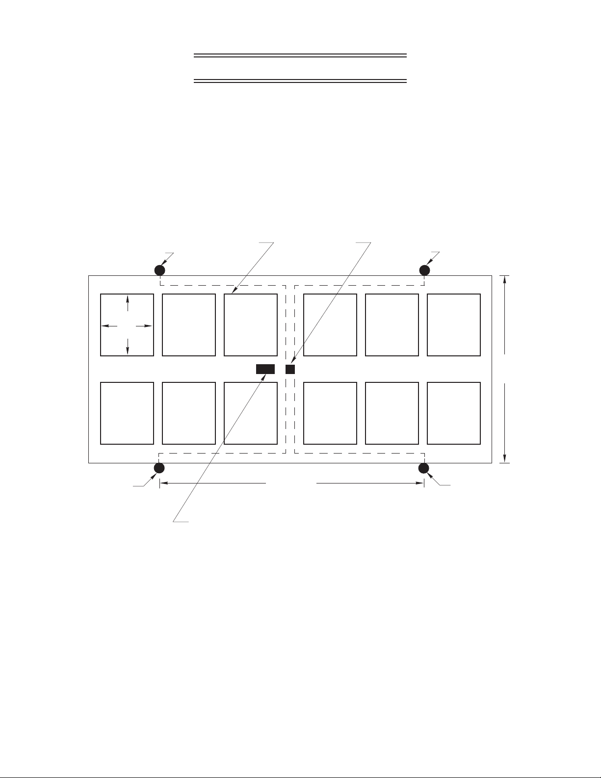
Registration Form
To be filled out by factory trained technician upon completion of system installation.
Mail to:
AIRMAR Technology Corporation
35 Meadowbrook Dr.
Milford, NH 03055-4613, USA
Date installed:
System part number: Serial number:
Customer: Site:
Installer: Company:
Transmitter output setting: Number of projectors:
Measured output of each projector: 1234
Depth of projectors: 1234
Length of projector cables: 1234
Description of power supply:
Layout: Draw shoreline, cages, batteries, transmitter and projectors (see Figure1).
Comments:
I verify that the system was installed according to the layout and specifications described above.
Customer Signature
17-5000 rev . 4 06/02
11
 Loading...