

Page 1
INSTALLATION INSTRUCTIONSOWNER’ S GUIDE &
Keel Mount
Depth Transducer
Model: CM422
US Patent 7,369,458. UK 2 414 077
WARNING: The transducer must be professionally
installed using accepted practices. The pocket must be
17-589-01 rev. 02 03/24/14
strong and watertight to reduce the risk of property
damage, personal injury, and/or death.
Follow the safety precautions below for optimal
product performance and to reduce the risk of
property damage, personal injury, and/or death.
Record the information found on the cable tag for future reference.
Part No._________________Date___________Frequency________kHz
WARNING: Always wear safety goggles and a dust
mask when installing.
WARNING: Immediately check for leaks when the
boat is placed in the water. Do not leave the boat
unchecked for more than three hours. Even a small
leak may allow considerable water to accumulate.
CAUTION: Do not install in the engine compartment or
other hot place. The transducer may fail if it overheats.
CAUTION: Always operate the transducer in water.
Operating in air will allow the transducer to overheat
resulting in failure.
CAUTION: Orient the transducer so the bosses on the
top are facing fore and aft—parallel to the centerline of
the boat.
CAUTION: The transducer must be flush with the
bottom of the hull for good performance.
CAUTION: Never pull, carry, or hold the transducer by
the cable. This may sever internal connections.
CAUTION: Never strike the transducer.
CAUTION: Never use solvents. Cleaners, fuel, sealants,
paint, and other products may contain solvents that can
damage plastic parts, especially the transducer’s face.
IMPORTANT: Please read the instructions completely
before proceeding with the installation. These
instructions supersede any other instructions in your
instrument manual if they differ.
Applications
• Keel mount in fiberglass hull only.
• Keel mount recommended for high-speed boats.
Hole Saw
Hole Saw 95mm or 3-3/4”
Mounting Location
CAUTION: Do not mount in line with or near water intake or
discharge openings or behind strakes, fittings, or hull irregularities
that will disturb the water flow.
Choose a Location
• In a cool well-ventilated area away from the engine to avoid
overheating.
• Where the transducer will be in contact with the water at all
times.
• Where the water flowing under the hull is smoothest with a
minimum of bubbles and turbulence (especially at high speeds).
Do not mount the transducer near water intake or discharge
openings; or behind strakes, fittings, or hull irregularities.
• Where the transducer beam will not be blocked by the propeller
shaft(s).
• Away from interference caused by power and radiation sources
such as: the propeller(s) and shaft(s), other machinery, other
echosounders, and other cables. The lower the noise level, the
higher the echosounder gain setting that can be used.
• Where there is working space inside the vessel.
Page 2
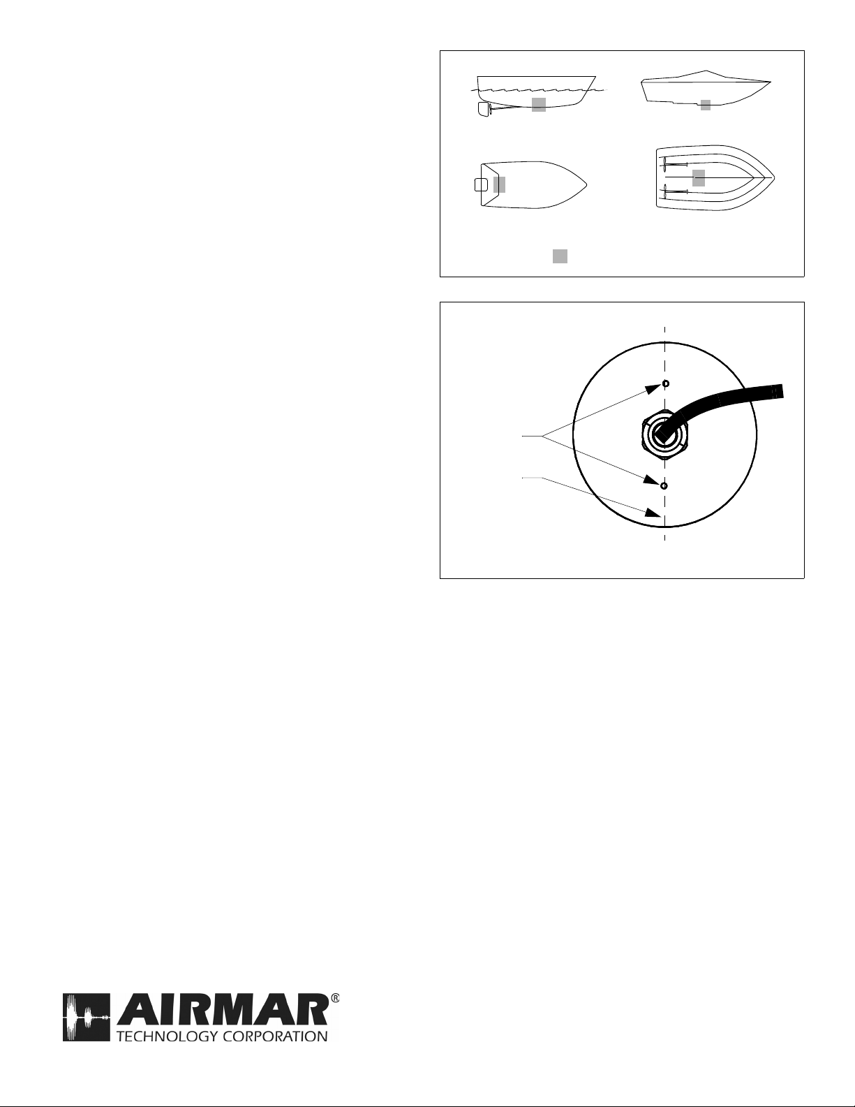
Boat Types (see Figure 1)
• Displacement hull powerboats—Locate amidships.
• Planing hull powerboats—Mount well aft and well inboard of
the first set of lifting strakes to ensure that the transducer will be
in contact with the water at high speeds.
Outboard and I/O—Mount just forward of the engine(s).
Inboard—Mount well ahead of the propeller(s) and shaft(s).
Stepped hull—Mount just ahead of the first step.
Installing
Orient the transducer, so one boss on the top is facing fore and
the other boss is aimed aft. The bosses must be parallel to the
centerline of the boat (see Figure 2).
Cable Routing & Connecting
displacement hull
outboard and I/O
Figure 1.
stepped hull
inboard
Best location for the transducer
Copyright © 2006 Airmar Technolog y Corp.
CAUTION: If the transducer came with a connector, do not
remove it to ease cable routing. If the cable must be cut and
spliced, use Airmar’s splash-proof Junction Box No. 33-035 and
follow the instructions provided. Removing the water-proof
connector or cutting the cable, except when using water-tight
junction box, will void the transducer warranty.
1. Route the cable to the echosounder being careful not to tear the
cable jacket when passing it through the bulkhead(s) and other
parts of the boat. Use grommets to prevent chafing. To reduce
electrical interference, separate the transducer cable from other
electrical wiring and the engine(s). Coil any excess cable and
secure it in place with cable ties to prevent damage.
2. Refer to your echosounder owner’s manual to connect the
transducer to the instrument.
Checking for Leaks
When the boat is placed in the water, immediately check around
the transducer for leaks. Note that very small leaks may not be
readily observed. Do not leave the boat in the water for more than
3 hours before checking it again. If a leak is observed, repeat the
installation procedures immediately.
Maintenance, Parts, & Replacement
Anti-fouling Paint
Surfaces exposed to salt water must be coated with anti-fouling
paint. Use water-based anti-fouling paint only. Never use ketone
based anti-fouling paint, since ketones can attack many plastics
possibly damaging the transducer. Apply anti-fouling paint every 6
months or at the beginning of each boating season.
Cleaning
Aquatic growth can accumulate rapidly on the transducer’s
surface, reducing its performance within weeks. Clean the surface
with a Scotch-Brite® scour pad and mild household detergent,
being careful to avoid making scratches. If the fouling is severe,
lightly wet sand it with fine grade wet/dry paper.
top view
NOTE: Orient one
boss forward
and one boss
toward the stern.
bosses
parallel to
centerline
of boat
Figure 2.Orient bosses fore and aft
Copyright © 2013 Airmar Technology Corp.
Transducer Replacement & Parts
The information needed to order a replacement Airmar transducer
is printed on the cable tag. Do not remove this tag. When ordering,
specify the part number, date, and frequency in kHz. For convenient reference, record this information near the top of page one.
Obtain parts from your instrument manufacturer or marine dealer.
Gemeco Tel: 803-693-0777
(USA) Fax: 803-693-0477
email: sales@gemeco.com
Airmar EMEA Tel: +33.(0)2.23.52.06.48
(Europe, Middle East, Africa) Fax: +33.(0)2.23.52.06.49
email: sales@airmar-emea.com
35 Meadowbrook Drive, Milford, New Hampshire 03055-4613, USA
•
www.airmar.com
Copyright © 2014 Airmar Technology Corporation. All rights reserved.
 Loading...