

Page 1
Junction Box Kit
INSTALLATION INSTRUCTIONS
for Replacement Speed/Temperature Insert
Models: B44V, B66VL, B744V, B744VC, B744VL, B744VLC
WARNING: Always wear safety goggles and a dust
mask when installing to avoid personal injury.
CAUTION: High Voltage Charge
The depth transducer may be storing a high voltage
charge. Accidental discharge could destroy the speed
sensor.
IMPORTANT: Read the instructions completely
17-033-02 rev. 07 12/14/10
before proceeding with the installation. These
instructions supersede any other instructions in your
instrument manual if they differ.
Applications
• These instructions are for a replacement speed/temperature
insert only. Installing a new insert will NOT solve problems with
depth sounding or fish finding.
• Determine which instructions to follow, either A or B, by looking
at your multisensor. If your multisensor has one cable, follow
instructions A on page 2. If your multisensor has two cables—
one from the depth transducer and one from the speed/
temperature insert—follow instructions B on page 3.
• If these instructions are followed carefully:
• The connections will not corrode
• The strain relief grommets will be water resistant and provide
excellent cable retention.
Before Installing
1. Be sure your new speed/temperature insert is the correct
replacement. Compare the length of the new insert with the
original insert (ignore the cable). If the new insert is more than
3mm (1/8") longer or shorter than the original insert, return it. To
obtain the correct insert, see “ Replacement Parts” on the back
of your multisensor’s owner’s guide.
2. Check the multisensor’s connector at the echosounder for
corrosion. If the connector’s pins are corroded, clean them.
Then test the multisensor to see if the problem has been
corrected.
3. Check the speed and temperature functions of the new insert.
Connect it to the echosounder and spin the paddlewheel.
Check for a reading of several knots. Check for the approximate
air temperature. If there is no reading(s), check the connection
and repeat the test. If there is still no reading(s) or it is
inaccurate, return the product to your place of purchase.
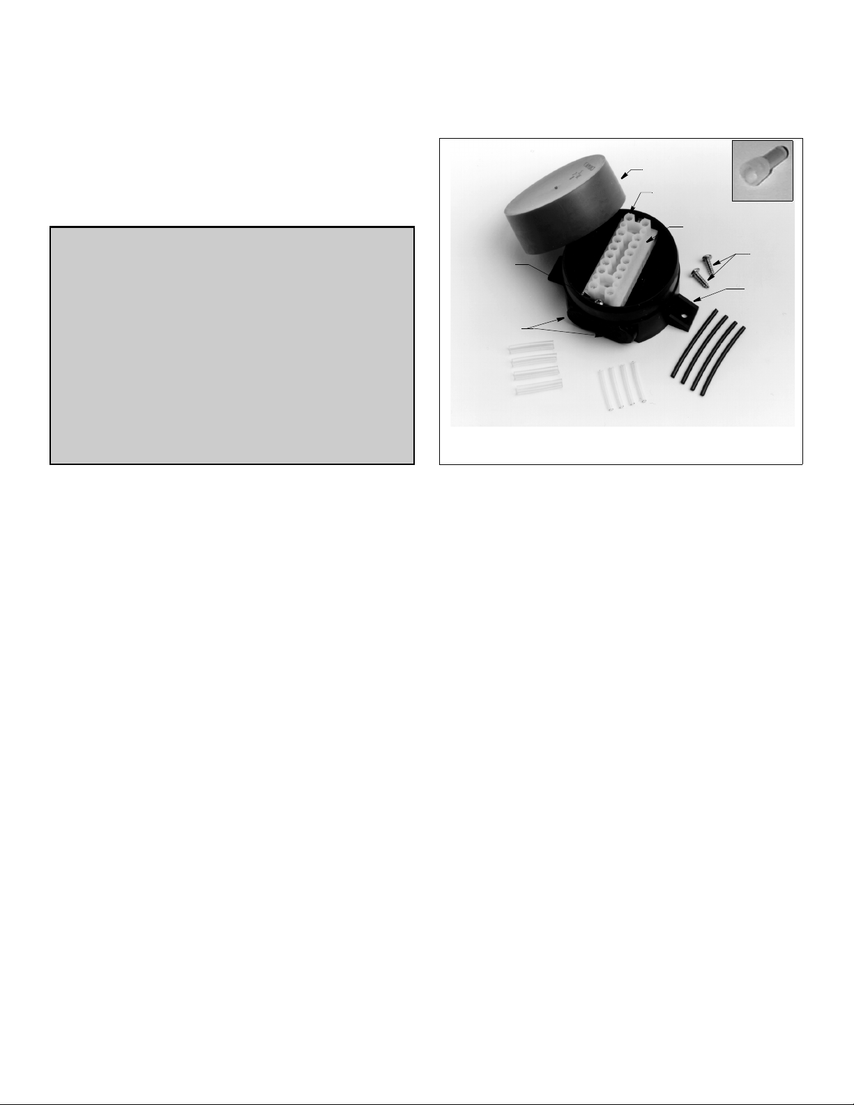
cap
terminal
block
screw (2)
grommet (4)
large diameter
sleeving
terminal screw
(16)
terminal block
mounting screws
small diameter
sleeving
Figure 1. Junction box and contents
Copyright © 2002, 2009 Airmar Techno logy Corp.
connector
mounting
screws
tab (2)
black sleeving
Tools & Materials
Safety goggles
Dust mask
Pencil
Drill
Drill bit: 3mm or 1/8"
Screwdrivers: Phillips and blade
Box-cutter knife (zip-cable installation)
Cutting pliers
Masking tape
Marker
Wire strippers
Alcohol
Crimping pliers (nine or ten-wire cables)
Anti-fouling paint (water-based) (mandatory in salt water)
Silicone lubricant or petroleum jelly
Mounting Location
1. Remove the red cap from the junction box and set the contents
aside (see Figure 1).
2. Select a convenient dry mounting location along the
multisensor’s cable route, preferably 1– 1.5 m (3–5') from the
multisensor but no more than 3m (10').
3. Position the junction box so the grommets are easily accessible
to the cable. Mark the location of the mounting holes.
4. At the marked location, drill two 3mm or 1/8" holes
approximately 10mm (3/8") deep. Do not fasten the junction
box in place at this time.
Page 2
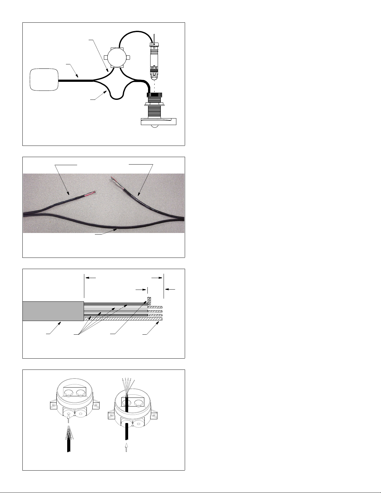
speed/temp half of zip-cable
Figure 4. Preparing the cables
cable
jacket
AIRMAR TRANSDUCER CABLE C344
colored
wires
bare
wire
folded
stripped end
Copyright © 2002, 2009 Airmar Techno logy Corp.
(contains red, green, brown,
echosounder
(printed half)
white, and bare wires)
zip-cable
depth-transducer
half of zip-cable
Figure 2. Splicing a zip-cable multisensor
Copyright © 2002, 2009 Airmar Tec hnology Corp.
zip-cable that is labeled
“Airmar Transducer Cable”
Cut the half of the
Preparing the Cables
C
3-5
5-75-7
insert
BA
multisensor
A. One Cable (Zip-cable) Multisensor
CAUTION: Do not cut the depth-transducer half of the zip-cable.
CAUTION: Do not puncture unused grommets.
1. Disconnect the multisensor from the echosounder.
2. On the junction box, use a small Phillips screwdriver to
puncture the center of both grommets marked 5-7 and one
grommet marked 3-5 (see Figure 2).
3. The multisensor’s cable is actually two separate cables joined
together. This type of cable is called zip-cable. Near the
mounting location of the junction box, separate the two halves of
the zip-cable. Carefully cut them apart with a box-cutter knife for
a distance of 0.5m (18"). Start at the junction box location and
move toward the sounder. Cut only the insulation between the
halves. DO NOT cut into the cables and expose the wires inside.
4. After you have separated the zip-cable, notice that one of the
halves is printed with the words “Airmar Transducer Cable” (see
Figure 3). The printed half of the zip-cable contains the speed
and temperature functions. Cut only the speed/temperature
half of the cable near the junction box. The wires inside will
be red and green. DO NOT cut the depth-transducer half of the
cable.
Figure 3. Cutting the speed/temperature half of a zip-cable
Figure 5. Pushing a cable through a grommet
2
Do not cut the
unmarked half
Copyright © 2002, 2009 Airmar Techn ology Corp.
remove outer jacket and foil shielding
5 -7
5 -7
Copyright © 2002, 2009 Airmar Tech nology Corp.
6cm (2 1/2")
5 -7
5 -7
13mm
(1/2")
NOTE: If the wires inside the cut-half of the cable are blue,
black, and orange, you have cut the depth-transducer side by
mistake. Now cut the speed/temp half of the zip-cable. Because
the depth-transducer cable has been cut, you will need to splice
it back together (see Figure 9). Puncture the center of the
remaining 3-5 grommet. Prepare the cut ends of the depthtransducer cable (see Figure 10). If you have a nine or ten wire
cable, use crimping pliers and the crimp connectors supplied.
Also use silicone lubricant or petroleum jelly to ease sliding
through the grommets.
5. Label the cables as follows with tape and a marker (see Figure 2).
• Cable A—cable to echosounder
• Cable B—cable to multisensor
• Cable C—new speed/temp insert cable
6. Cables A and B—Strip 6cm (2-1/2") of the outer jacket and foil
shield from the cut ends (see Figure 4).
7. Cable A—Strip 13mm (1/2") of insulation from the end of each
colored wire.
8. Cable B—Only the bare wire will be used. Cut-off all the colored
wires.
9. Bend the stripped wires of each cable back against its cable
jacket (see Figure 5). Apply alcohol to the cut end of each cable
jacket to ease sliding. (Do not use any other lubricant to ease
sliding. It will interfere with sealing the grommets.) Push about
20cm (8") of each cable through the appropriate grommet until
all the wires are inside the junction box (see Figure 2). Bend the
wires back to their original position (see Figure 5).
10.Slide a black sleeve over each bare wire and position it against
the cable jacket. For ease in holding the sleeves in place and
connecting to the terminals, fold the stripped ends of each wire
in half. Twist the ends and bend them 90
° (see Figure 4).
11.Go to “Connecting & Testing” on page 3 and follow the
instructions.
Page 3

B. Two-cable Multisensor
CAUTION: Do not cut the depth-transducer cable.
CAUTION: Do not puncture unused grommets.
speed/temp
cable
3-53-5
insert
1. Disconnect the multisensor from the echosounder.
2. On the junction box, use a small Phillips screwdriver to
puncture the center of both 5-7 grommets only (see Figure 6).
3. Near the marked location for the junction box, cut the cable
leading to the speed/temp insert ONLY. Do not cut the depth
transducer cable.
4. Strip 6cm (2-1/2") of the outer jacket and foil shield from the
cable ends (see Figure 4).
5. Strip 13mm (1/2") of insulation from the end of each colored wire.
6. Bend the stripped wires of each cable back against its cable
jacket (see Figure 5). Apply alcohol to the cut end of each cable
jacket to ease sliding. (Do not use any other lubricant to ease
sliding. It will interfere with sealing the grommets.) Push about
20cm (8") of each cable through a grommet until all the wires
are inside the junction box (see Figure 6). Bend the wires back
to their original position (see Figure 5).
7. Slide a black sleeve over each bare wire and position it against
the cable jacket. For ease in holding the sleeves in place and
connecting to the terminals, fold the stripped ends of each wire
in half. Twist the ends and bend them 90
° (see Figure 4).
Connecting & Testing
echosounder
depth
transducer
cable
Figure 6. Splicing a two-cable multisensor
Copyright © 2002, 2009 Airmar Techno logy Corp.
red
green
white
brown
terminals
A
bare wire
with black
sleeve
echosounder
Figure 7. Connecting a zip-cable multisensor
Copyright © 2002, 2009, 2010 Airmar Technology Corp.
B
multisensor
multisensor
red
green
white
brown
C
bare wire
with black
sleeve
speed/temp
insert
CAUTION: Make certain there are no bare wires, frayed strands,
or loose ends to cause shorting.
CAUTION: Zip-cable multisensor—If the depth-transducer half
of the cable (with the blue, black, orange, and bare wires) has
been cut, re-connect it FIRST before connecting the new speed/
temp insert (see Figure 11 on page 4).
1. Insert the stripped end of a colored wire from the echosounder
cable A into the first square opening in the side of the terminal
block (see Figure 7 or 8). Tighten the terminal screw until the
wire is held firmly. Connect each wire in turn including the bare
wire.
2. Connect each matching colored wire and bare wire from the
new speed/temp insert (cable C) to the corresponding terminal.
Zip-cable multisensor—Twist the bare wire from cable B and
the bare wire from cable C together. Connect the twisted pair of
bare wires to the terminal (see Figure 7). This shields the depth
transducer from acoustic noise.
3. Visually inspect all the wires. Make certain the sleeving
completely covers any bare wire(s). There should be no frayed
strands or loose ends to cause shorting. If any bare wire is
visible, shorten the stripped end and reconnect it to the terminal.
4. Connect the cable to the echosounder and turn it ON.
5. Check for the approximate air temperature.
6. Spin the new paddlewheel and look for a speed reading.
NOTE: If the new insert does not work properly, the wiring may
be incorrect. Return to step 1 and recheck your wiring.
terminals
white
bare wire
with sleeve
red
red
white
bare wire
with sleeve
AC
brown
green
echosounder
Figure 8. Connecting a two-cable multisensor
speed/temp half of zip-cable
(contains red, green, brown,
white, and bare wires)
Copyright © 2002, 2010 Airmar Technology Corp.
(printed half)
3-5 3-5
A
5-7 5-7
brown
green
C
speed/ temp
insert
insert
B
echosounder
depth-transducer
half of zip-cable
(contains blue, black,
orange, and bare wires)
DE
multisensor
Figure 9. Splicing both halves of a zip-cable
Copyright © 2002, 2009 Airmar Techno logy Corp.
3
Page 4

Closing & Mounting
1. Apply alcohol to each cable jacket inside the junction box to ease
sliding. Grasp each cable from outside the box and pull until only
25mm (1") of the cable jacket is left inside. This will invert the
grommets to seal the junction box.
2. Arrange the wires neatly inside the junction box.
3. Place the terminal block inside the junction box. Secure the
ends with the terminal block screws provided (see Figure 1).
4. Close the box using the red cap. Expel the excess air inside the
junction box by placing a thumb on the center of the red cap
and applying pressure for 30 seconds.
5. Screw the junction box to the selected mounting surface using
the two #6 x 1/2" (13mm) screws provided.
Anti-fouling Paint
Aquatic growth can accumulate rapidly on the speed / temp insert
reducing its performance within weeks. Surfaces exposed to salt
water must be coated with anti-fouling paint. Use water-based
anti-fouling paint only. Never use ketone based paint since
ketones can attack many types of plastic. Paint the following
surfaces:
• Exposed end of the insert
• Outside wall of the insert below the lower O-ring
• Paddlewheel cavity
• Paddlewheel
Installing the Speed Temperature Insert
WARNING: Different speed/ temperature inserts are attached to
the multisensor in different ways. See your multisensor’s owner’s
guide for more details.
WARNING: O-ring must be intact and well lubricated to make a
watertight seal.
black
bare wire with
black sleeve
shielded pair
with clear
sleeve
echosounder
speed/ temp
red
green
white
bare wire with
black sleeve
remove outer jacket and foil shielding
6cm (2 1/2")
13mm
(1/2")
Figure 10. Preparing the cut ends of the
depth-transducer half of a zip-cable
Copyright © 2002, 2009 Airmar Tec hnology Corp.
CAUTION: Reconnect the
depth transducer before
connecting the new
speed/ temp insert
terminals
D
depth
A
B
multisensor
remove
insulation
bare
wire
blueblue
black
bare wire with
black sleeve
shielded pair
with clear
sleeve
E
depth
multisensor
speed/ temp
insert
C
red
green
white
brownbrown
bare wire with
black sleeve
WARNING: Always attach the safety wire to prevent the insert
from backing out in the unlikely event that the cap nut and/or
insert nut fails or is screwed on incorrectly.
1. Check the O-rings on the new insert (replace if necessary) and
lubricate them with silicone lubricant or petroleum jelly.
2. Remove the failed speed/temperature insert from the housing.
If desired, save it for replacement parts. The paddlewheel and
shaft may be usable.
3. Slide the new insert into the valve assembly with the arrows on
the top pointing forward until it is fully seated.
• Insert nut—Use a twisting motion until the keys fit into the
notches. (The insert fits one way only.) Screw the insert nut
in place and hand-tighten only. Do not over tighten.
• Safety chain or Strap assembly—Reattach the safety
chain/strap assembly to the cable. Slide the retaining pin
through the holes and secure it with the safety ring(s).
4. Reattach the safety wire.
®
AIRMAR
35 Meadowbrook Drive, Milford, New Hampshire 03055-4613, USA
TECHNOLOGY CORPORATION
4
Copyright © 2002 - 2010 All rights reserved.
Figure 11. Reconnecting a depth transducer and
connecting new speed/temp insert
Copyright © 2002, 2010 Airmar Techn ology Corp.
Parts
Obtain parts from your instrument manufacturer or marine dealer.
Gemeco Tel: 803-693-0777
(USA) Fax: 803-693-0477
email: sales@gemeco.com
Airmar EMEA Tel: +33.(0)2.23.52.06.48
(Europe, Middle East, Africa) Fax: +33.(0)2.23.52.06.49
email: sales@airmar-emea.com
www.airmar.com
 Loading...