

Page 1
INSTALLATION INSTRUCTIONSOWNER’S GUIDE &
Thru-Hull, Retractable
Long-stem Sensors
Models: B122, DST800L, ST700
U.S. Patents.: 6,904,798; 7,110,908; 7,352,171. UK Patents: 2 407 874; 2 409 527
Follow the safety precautions below to reduce
the risk of poor product performance, property
damage, personal injury, and/or death.
WARNING: Always wear safety goggles and a dust
mask when installing.
WARNING: Fairing—The High-Performance Fairing
requires an anti-rotation bolt. Failure to install the anti-
17-284-01 rev. 05 05/15/11
rotation bolt may result in the fairing rotating while the
boat is underway. The effect may be violent
movement and loss of steering.
WARNING: Fairing—The fairing must be installed
parallel to the keel to ensure proper boat handling.
WARNING: Fairing—Do not install a fairing that has
been mis-cut. Replace it. Failure to do so may result in
the fairing rotating while the boat is underway.
- Cutting the fairing at an angle greater than the 35°
maximum allowed will cut into the sensor and/or bolt
pocket, thus weakening the fairing.
- Do not allow any gap between the fairing and the hull that
is greater than 3mm (1/8"). When the boat is underway,
water will enter any gaps and push against the fairing with
considerable force.
Record the information found on the cable tag for future reference.
PN:___________________Date___________Frequency_________kHz
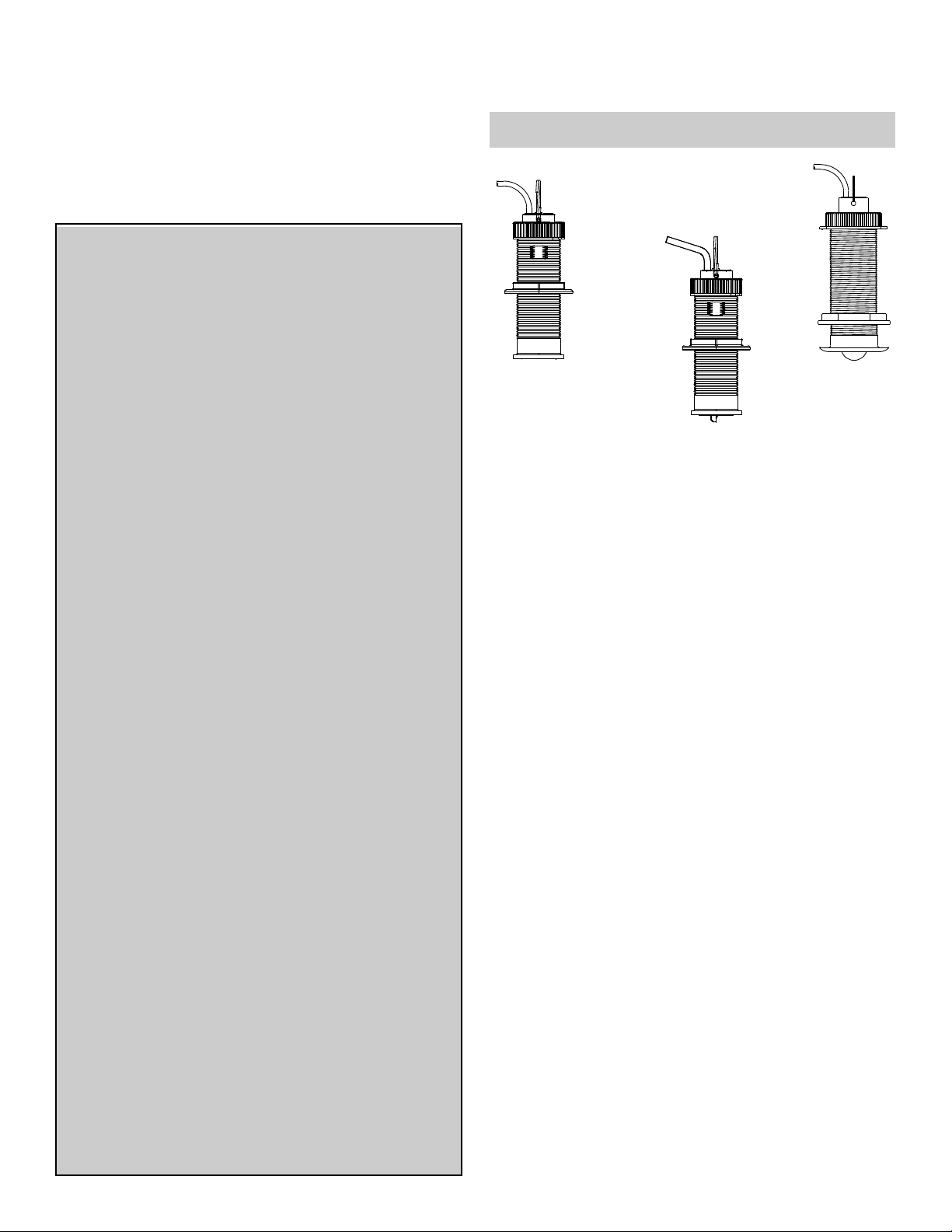
B122
depth
flush
B122 housing
DST800L
TRIDUCER®
Multisensor
flush
B122 housing
IMPORTANT: Read the instructions completely before
proceeding with the installation. These instructions supersede any
other instructions in your instrument manual if they differ.
ST700
speed &
temperature
low-profile
B123 housing
Application
• Recommended for a thick hull.
• Bronze housing recommended for fiberglass or wood hull.
Never install a bronze housing in a metal hull because electrolytic
corrosion will occur.
• Flush-mount accommodates a deadrise angle up to 10°.
• Fairing accommodates a deadrise angle up to 28°.
• Maximum hull thickness with 35° deadrise angle and fairing
(measured perpendicular to the water surface): 47 mm (1-7/8")
WARNING: Do not over tighten the hull nut and nut on
the anti-rotation bolt, crushing the hull and/ or fairing.
WARNING: The O-rings must be intact and well
lubricated to make a watertight seal.
WARNING: The valve is not a watertight seal!
the insert or blanking plug is fully inserted into the housing,
and the cap nut is screwed on completely.
Be sure
WARNING: Always attach the safety wire to prevent the
insert or blanking plug from backing out in the unlikely
event that the cap nut fails or is screwed on incorrectly.
WARNING: Immediately check for leaks when the
boat is placed in the water. Do not leave the boat
unchecked for more than three hours. Even a small
leak may allow considerable water to accumulate.
CAUTION: Never install a metal sensor on a vessel
with a positive ground system.
CAUTION: Never pull, carry, or hold the sensor by its
cable; this may sever internal connections.
CAUTION: Never strike the sensor.
CAUTION: The arrow on the top of the insert must
point forward toward the bow when installed.
CAUTION: Never use solvents. Cleaners, fuel,
sealants, paint, and other products may contain strong
solvents, such as acetone, which attack many
plastics, greatly reducing their strength.
Pretest
Connect the insert to the instrument and spin the paddlewheel if any.
Check for the approximate air temperature and any speed reading . If
there is no reading(s), check all the connections and repeat the test. If
there is still no reading(s) or it is inaccurate, return the product to your
place of purchase.
Tools & Materials
Safety goggles
Dust mask
Water-based anti-fouling paint (mandatory in salt water)
Electric drill with 10mm (3/8") or larger chuck capacity
Drill bits: 3mm or 1/8" (pilot hole)
11mm or 7/16" (anti-rotation bolt hole
Hole saw: 51mm or 2" (flush mount
57mm or 2-1/4"
Angle finder (some installations)
Band saw (faring installation)
Rasp or power tool (fairing installation)
Sandpaper
Mild household detergent or weak solvent (such as alcohol)
Marine sealant (suitable for below waterline)
Slip-joint pliers
Mallet (some installations)
Countersink tool (flush installation)
Grommet(s) (some installations)
Cable ties
Installation in a cored fiberglass hull (see page 6)
Hole saw for hull interior:
Sensor: min. 60mm or 2-3/8"
Anti-rotation bolt: min. 19mm or 3/4"
Cylinder, wax, tape, and casting epoxy
(installation with adapter ring)
Page 2
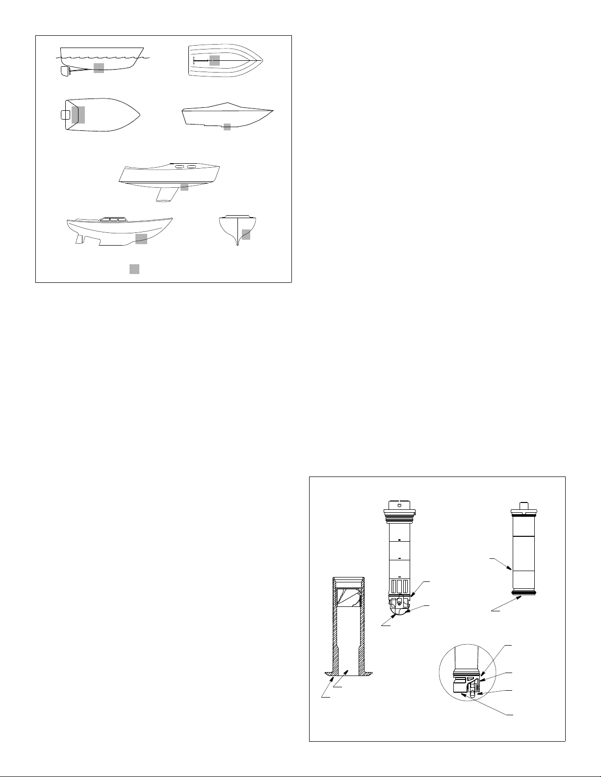
large displacement hulls
outboard and I/O
fin keel sailboats
planing hulls
small displacement hulls
stepped hull
installation location and operating results of similar boats before
proceeding.
• Fin keel sailboat—Mount on or near the centerline and forward
of the fin keel 300–600mm (1–2').
• Full keel sailboat—Locate amidships and away from the keel
at the point of minimum deadrise angle.
About the High-Performance Fairing
Nearly all vessels have some deadrise angle at the mounting
location. If the sensor is mounted directly to the hull, the transducer
beam will be tilted to the side at the same angle as the deadrise. A
fairing is strongly recommended if the deadrise angle exceeds 10°.
• Orients the transducer beam straight down by mounting the
sensor parallel to the water surface (see Figure 3).
• Mounts the sensor deeper in the water for clean flow under the
transducer face.
• Long streamlined shape directs the water around the sensor to
minimize drag.
full keel sailboats
Figure 1.
Copyright © 2006 - 2011 Airmar Technol ogy Corp
Best location for sensor
Mounting Location
CAUTION: Do not mount near water intake or discharge
openings, or behind strakes, fittings, or hull irregularities that will
disturb the water flow.
CAUTION: Never mount the speed sensor directly ahead of a
depth transducer, since turbulence generated by the
paddlewheel’s rotation will adversely effect the depth transducer’s
performance, especially at high speeds. Mount side-by-side.
• The water flowing under the hull must be smooth with a
minimum of bubbles and turbulence (especially at high speeds).
• The sensor must be continuously immersed in water.
• The transducer beam must be unobstructed by the keel or
propeller shaft(s).
• Choose a location away from interference caused by power and
radiation sources such as: the propeller(s) and shaft(s), other
machinery, other echosounders, and other cables. The lower
the noise level, the higher the echosounder gain setting that
can be used.
• If the sensor will be installed without a fairing, choose a location
with a minimal deadrise angle, less than 10°, so the transducer
beam will be aimed at the bottom.
• Choose an accessible spot inside the vessel with adequate
headroom for the height of the housing, tightening the nuts, and
removing insert. Allow a minimum of 200 mm (7-3/4") above the
top of the housing.
Hull Types (see Figure 1)
• Displacement hull powerboat—Locate amidships near the
centerline. The starboard side of the hull where the propeller
blades are moving downward is preferred.
• Planing hull powerboat—Mount well aft, on or near the
centerline, and well inboard of the first set of lifting strakes to
ensure that the sensor will be in contact with the water at high
speeds. The starboard side of the hull where the propeller
blades are moving downward is preferred.
Outboard and I/O—Mount just forward of the engine(s).
Inboard—Mount well ahead of the propeller(s) and shaft(s).
Stepped hull—Mount just ahead of the first step.
Boat capable of speeds above 25kn (29MPH)—Review the
2
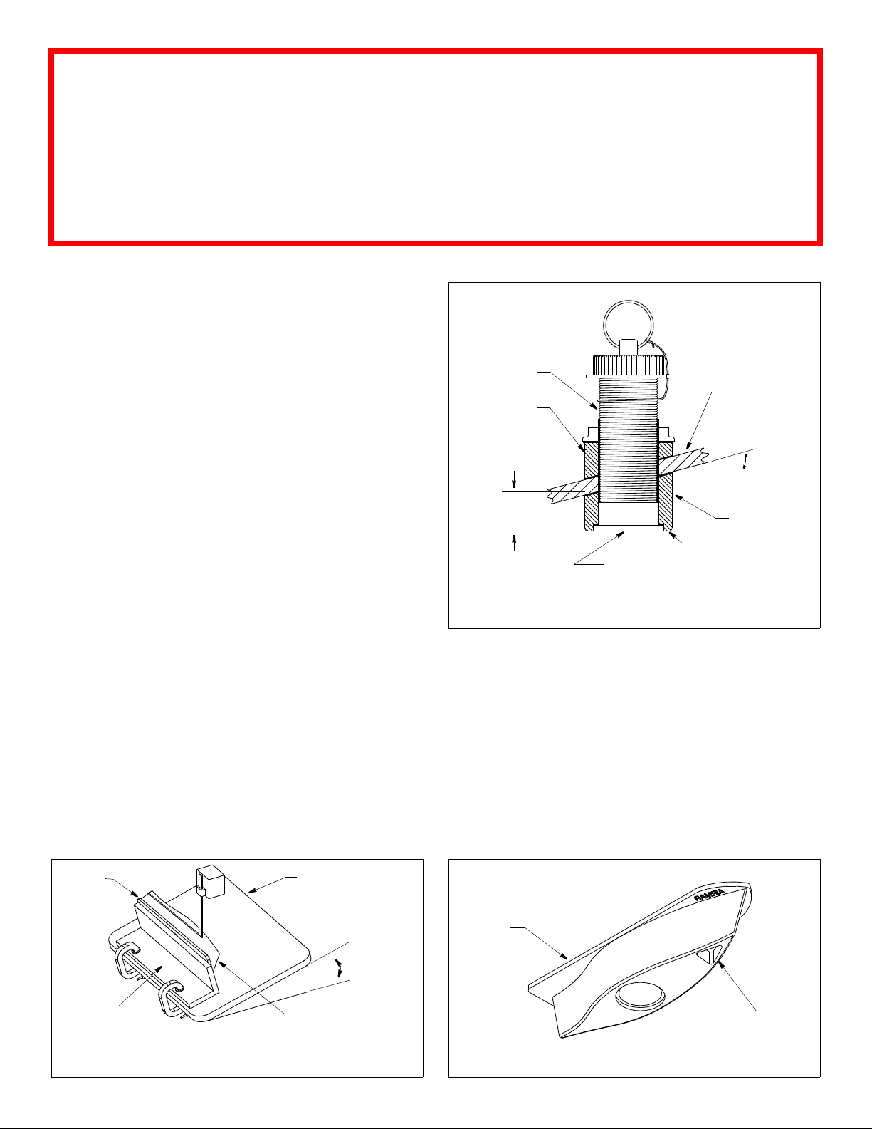
Anti-fouling Paint
Marine growth can accumulate rapidly on the sensor’s surface
reducing performance in weeks. Surfaces exposed to salt water
must be coated with anti-fouling paint. Use water-based anti-
fouling paint only. Never use ketone-based paint, since ketones
can attack plastics possibly damage the sensor.
It is easier to apply antifouling paint before installation, but allow
sufficient drying time. Reapply paint every 6 months or at the
beginning of each boating season. Paint the following surfaces
(see Figure 2 ):
• Exterior flange of housing
• Bore of housing up 30mm (1-1/4")
• Insert and Blanking Plug:
- B122, Blanking Plug—Outside wall below lower joint
Exposed end
- DST800L, ST700—Outside wall below lowest O-ring
Any exposed end
Paddlewheel
Paddlewheel cavity
insert
B122/ Blanking Plug
exposed end
outside wall
below lower
O-ring
paddlewheel
cavity
paddlewheel
exposed end
housing
(ST700 shown)
bore up 30mm (1-1/4")
exterior flange
insert
ST700
outside wall
below joint
outside wall
below
lowest O-ring
paddlewheel
cavity
paddlewheel
insert detail
DST800L
Figure 2. Anti-fouling paint
Copyright © 2001 - 2011 Airmar Technol ogy Corp.
Page 3
WARNING
Installation of the anti-rotation bolt is mandatory in a High-Performance Fairing!
Failure to install the anti-rotation bolt may result in the fairing rotating while the boat is
underway. The effect may be violent movement and loss of steering. This could result in
serious injury or death to passengers and/or damage to the boat or other property.
Installation with Fairing: Suitable for B122, DST800L
Hole Drilling: Sensor
Cored fiberglass hull—Follow separate instructions on page 7.
1. Drill a 3mm or 1/8" pilot hole perpendicular to the waterline from
inside the hull. If there is a rib, strut, or other hull irregularity near
the selected mounting location, drill from the outside.
2. Using the 51 mm or 2" hole saw, cut a hole from outside the
boat (see Figure 3). Be sure to hold the drill plumb, so the hole
will be perpendicular to the water surface.
Cutting the Fairing
CAUTION: The end of the fairing with the arrows/triangular
recess always points forward toward the bow when installed. Be
sure to orient the fairing on the band saw so the angle cut
matches the intended side of the hull and not the mirror image.
CAUTION: The housing must be flush with the fairing for smooth
water flow under the sensor.
aft view
sensor
backing block
min. fairing
thickness
13mm (1/2")
transducer face
hull
slope of hull
deadrise
angle
parallel to
water surface
fairing
NOTE: fairing must
be flush with housing
1. Measure the deadrise angle of the hull at the selected mounting
location using an angle finder (see Figure 3). Check to be sure
the angle does not exceed the 35° maximum allowed.
2. Tilt the band saw table to the measured angle and secure the
cutting fence (see Figure 4).
3. Place the fairing on the table so the cutting guide rests against
the fence (see Figures 4 and 5). The end with the triangular
recess will be pointing toward you for installation on the
starboard side of the boat or pointing away from you for
installation on the port side.
4. Adjust the cutting fence so the fairing will be cut in about two
equal parts. The section that will become the fairing must be a
minimum of 13mm (1/2") at its thinnest dimension (see Figure 3).
Cutting the fairing at an angle greater than 35° will cut into the
sensor and/or bolt pocket, thus weakening the fairing.
cutting
guide
cutting
fence
Figure 4. Cutting the fairing
Copyright © 2006 Airmar Technolog y Corp. Copyright © 2006 Airmar Technolog y Corp.
band saw
table
deadrise
angle
end with arrow
and triangular recess
for installation on
starboard side of hull
Figure 3. Measuring the deadrise angle
and fairing thickness
Copyright © 2006 - 2011 Airmar Technol ogy Corp.
(B122 shown)
5. Recheck steps 1 through 4. Then cut the fairing.
6. When the boat is underway, especially at high speeds, water
will enter gaps and push against the fairing with considerable
force. Shape the fairing to the hull as precisely as possible with
a rasp or power tool. If there is a gap of more than 3mm (1/8"),
replace the fairing.
7. Check to be sure the housing is flush with the fairing. If it is
recessed more that 0.5mm (1/64") inside the fairing, you may
shim the housing or carefully file/sand the fairing.
8. Use the remaining section of the fairing with the cutting guide
for the backing block.
cutting
guide
triangular
recess for
anti-rotation bolt
Figure 5. High-performance fairing
3
Page 4

cap nut
(bronze/ plastic)
NOTE
: Notch
in housing
must face
forward toward
the bow
anti-rotation
bolt
BOW ►
detail
backing
block
fairing
Figure 6. Bedding and installing the anti-rotation bolt (DST800L shown)
Copyright © 2006 Airmar Technology Corp.
Hole Drilling: Anti-rotation Bolt
Cored fiberglass hull—Follow separate instructions on page 7.
To locate and drill the hole for the anti-rotation bolt, use the fairing
as a guide. This will ensure that the hole is perpendicular to the
waterline and not drilled at the angle of the hull.
1. Dry fit the housing in the fairing. Seat the housing firmly in the
recess in the fairing (see Figure 6).
2. Slide the housing with the fairing in place into the mounting
hole. Hold the fairing parallel to the keel with the triangular
recess in the fairing is pointing forward toward the bow.
Using the bolt hole in the fairing as your guide, drill a 3mm or
1/8" pilot hole through the hull for the anti-rotation bolt.
3. With the 11 mm or 7/16" bit and using the bolt hole in the fairing
as your guide, drill the hole through the hull for the anti-rotation
bolt.
4. Remove the assembly from the mounting hole.
aft view
pull ring
insert
backing block
hull
safety wire
cap nut
housing
hull nut
nut &
washer
hull
triangular plug
curved surface
facing outward
marine
sealant
5. Sand and clean the area around both holes, inside and outside, to
ensure that the sealant will adhere properly to the hull. If there is
any petroleum residue inside the hull, remove it with either mild
household detergent or a weak solvent, (alcohol) before sanding.
Bedding the Housing & Fairing
CAUTION; Be sure the surfaces to be bedded are clean and dry.
1. Remove the housing from the fairing.
2. Apply a 2 mm (1/16") thick layer of marine sealant around the
flange of the housing that will contact the fairing and up the
sidewall of the housing (see Figure 7). The sealant must extend
6mm (1/4") higher than the combined thickness of the fairing,
hull, backing block, and the hull nut. This will ensure there is
sealant in the threads to seal the hull and to hold the hull nut
securely in place.
3. Apply a 2 mm (1/16") thick layer of marine sealant to the
following surfaces:
- Fairing that will contact the hull
- Backing block that will contact the hull.
- Hull nut that will contact the backing block
Installing the Housing & Fairing
1. Seat the housing firmly within the recess in the fairing (see
Figure 6). Align the notch in the top of the housing pointing
forward toward the anti-rotation bolt hole (bow).
2. From outside the hull, push the housing (with the fairing in
place) into the mounting hole using a twisting motion to
squeeze out excess sealant.
3. From inside the hull, Slide the backing block onto the housing.
Seat the backing block firmly against the hull.
4. Screw the hull nut in place. Do not tighten at this time.
Bedding & Installing the Anti-rotation Bolt
sealant on flange, side wall,
fairing, backing block, hull nut
Figure 7. Bedding the housing and fairing (B122 shown)
Copyright © 2006 Airmar Technolog y Corp.
4
fairing
CAUTION: Be sure the surfaces to be bedded are clean and dry.
CAUTION: For smooth water flow under the sensor be sure the
external surface of the triangular plug is flush with the curved
surface of the fairing.
1. Apply a 2 mm (1/16") thick layer of marine sealant to the antirotation bolt including the flange (see Figure 6). The sealant
must extend 6mm (1/4") higher than the combined thickness of
Page 5

the fairing, hull, backing block, washer, and nut. This will ensure
that there is marine sealant on the threads to seal the hull and
hold the nut securely in place.
2. Apply a 2mm (1/16") thick layer of marine sealant to the surface
of the washer that will contact the backing block.
3. Push the anti-rotation bolt through the fairing and into the hull.
4. From inside the hull, screw the washer (sealant side down) and
the nut onto the anti-rotation bolt.
5. Use slip-joint pliers to tighten both the hull nut and the antirotation bolt. Do not over tighten crushing the fairing or hull.
Cored fiberglass hull—Do not over tighten crushing the hull.
Wood hull—Allow for the wood to swell.
6. Use marine sealant to over-fill the hollow in the yellow triangular
plug. Apply a 2mm (1/16") thick layer of marine sealant to the
three sides of the plug that form the triangle. The sealant will
hold the plug firmly within the fairing and fill any gap between
the anti-rotation bolt and the plug.
7. The yellow triangular plug fits one way only. Push the yellow
plug into the recess in the fairing until it is FLUSH with the
outside of the fairing. This will squeeze out excess sealant. If
necessary, tap it into place with a mallet.
NOTE: If the triangular plug is slightly recessed within the
fairing, use sealant to fill the gap. The plug must be flush with
the fairing for good performance.
8. When the boat is underway, especially at high speeds, water
will enter gaps and push against the fairing with considerable
force. Fill any gaps between the fairing and the hull with marine
sealant. If there is any gap greater than 3mm (1/8”), replace
the fairing. Remove the excess sealant on the outside of the
fairing and hull to ensure smooth water flow under the sensor.
9. Continue with “Installing the Insert” on page 6.
Flush & Low-Profile Mount: Suitable for All Models
Hole Drilling
Cored fiberglass hull—Follow separate instructions on page 7.
1. Drill a 3 mm or 1/8" pilot hole from inside the hull. If there is a rib,
strut, or other hull irregularity near the selected mounting
location, drill from the outside.
2. Using the appropriate size hole saw, cut a hole perpendicular to
the hull from outside the boat (see figure 8).
Flush housing—Use a countersink tool to make a ‘seat’ in the
hull.
3. Sand and clean the area around the hole, inside and outside, to
ensure that the marine sealant will adhere properly to the hull. If
there is any petroleum residue inside the hull, remove it with either
mild household detergent or a weak solvent before sanding.
Bedding
CAUTION: Be sure the surfaces to be bedded are clean and dry.
Apply a 2mm (1/16") thick layer of marine sealant around the flange
of the housing that will contact the hull and up the sidewall of the
housing (see Figure 8). The sealant must extend 6mm
(1/4") higher than the combined thickness of the hull, washer, the
hull nut, and any adaptor ring. This will ensure there is sealant in
the threads to seal the hull and to hold the hull nut securely in place.
Adaptor ring—Slide the adaptor ring onto the housing. Apply
additional marine sealant to the surfaces of the ring that will
contact the hull, filling any cavities in and around the ring.
Installing
1. From outside the hull, push the housing into the mounting hole
using a twisting motion to squeeze out excess marine sealant
(see Figure 8). Align the notch in the top of the housing pointing
forward toward the bow.
2. From inside the hull, slide the washer onto the housing.
3. Screw the hull nut in place, being sure the notch is still
positioned forward toward the bow. Tighten with slip-joint pliers.
Cored Fiberglass Hull—Do not over tighten, crushing the hull.
Wood hull—Allow the wood to swell before tightening the hull nut.
4. Remove any excess marine sealant on the outside of the hull to
ensure smooth water flow under the sensor.
flush mount
B122 or DST800L
low-profile mount with adapter
housing
hull nut
washer
hull
marine sealant
Figure 8. Bedding and installing without a fairing
Copyright © 2006 Airmar Technology Cor p.
B122 or DST800L
notchnotch
adaptor
ring
BOW ►
housing
hull nut
washer
hull
low-profile mount
ST700
marine sealant on
sidewall and flange
notch
5
Page 6

BOW ►
BOW ►
pull
ring
key
large
O-ring
small
O-ring
Figure 9. B122 insert/blanking plug
Copyright © 2006 - 2011 Airmar Technol ogy Corp.
Figure 10. DST800L insert
Copyright © 2011 Airmar Technolog y Corp.
Installing the Insert
1. Slide the cap nut along the cable until it rests on top of the insert.
Attach the pull ring capturing the cap nut (see Figure 9, 10, or
11). Attach the pull ring to the blanking plug in a similar fashion.
2. The O-rings must be intact and well lubricated to make a
watertight seal. After the marine sealant cures, inspect the Orings on the insert (replace if necessary) and lubricate them
with the silicone lubricant supplied.
3. Slide the insert into the housing. Point the arrow on the top
forward toward the bow. Seat the insert into place with a
twisting motion until the key fits into the notch. Be careful not to
rotate the outer housing and disturb the sealant. Screw the cap
nut in place and hand tighten only. Do not over tighten.
4. Attach the safety wire to prevent the insert from backing out in
the unlikely event that the cap nut fails or is screwed on
incorrectly (see Figure 12). Wrap one end of the safety wire
tightly around the housing and twist it together with the long
end. Keeping the wire taut throughout, lead it straight up and
through the eye in the cap nut. Loop the wire through the pull
ring and twist it securely to itself.
pull ring
insert
safety cap nut
wire
(plastic)
arrow
pull
ring
key
large
O-ring
small
O-ring
shaft
flat side
of blade
faces bow
Figure 11. ST700 insert
Copyright © 2001 Airmar Technolo gy Corp.
arrow
pull ring
key
large
O-ring
medium
O-ring
small
O-ring
shaft
flat side
of blade
faces bow
Cable Routing & Connecting
CAUTION: If your sensor came with a connector, do not remove it
to ease cable routing. If the cable must be cut and spliced, use
Airmar’s splash-proof Junction Box No. 33-035 and follow the
instructions provided. Removing the waterproof connector or
cutting the cable, except when using a water-tight junction box,
will void the sensor warranty.
1. Route the cable to the instrument, being careful not to tear the
cable jacket when passing it through the bulkhead(s) and other
parts of the boat. Use grommet(s) to prevent chaffing. To reduce
electrical interference, separate the sensor cable from other
electrical wiring and the engine. Coil any excess cable and
secure it in place using cable ties to prevent damage.
2. Refer to the echosounder owner’s manual to connect the
sensor to the instrument.
Checking for Leaks
When the boat is placed in the water, immediately check around
the thru-hull sensor for leaks. Note that small leaks may not be
readily observed. Do not to leave the boat in the water for more
than 3 hours before checking it again. If there is a small leak,
there may be considerable bilge water accumulation after 24
hours. If a leak is observed, repeat the bedding and installing
procedures immediately.
Figure 12. Safety wire (ST700 shown)
Copyright © 2001 Airmar Technology Corp.
6
Page 7

Installation in a Cored Fiberglass Hull
The core (wood or foam) must be cut and sealed carefully. The
core must be protected from water seepage, and the hull must be
reinforced to prevent it from crushing under the hull nut allowing
the housing to become loose.
CAUTION: Completely seal the hull to prevent water seepage into
the core.
1. Drill a 3mm or 1/8" pilot hole from inside the hull. If there is a rib,
strut, or other hull irregularity near the selected mounting
location, drill from the outside. If the hole is drilled in the wrong
location, drill a second hole in a better location. Apply masking
tape to the outside of the hull over the incorrect hole and fill it
with epoxy.
Fairing—Drill perpendicular to the waterline (see Figure 13).
No fairing—Drill perpendicular to the hull (see Figure 14).
2. Using the 51 mm or 2" hole saw, cut a hole from outside the hull
through the outer skin only. Be sure to hold the drill plumb, so
the hole will be perpendicular to the water surface.
NOTE: The optimal interior hole diameter is affected by the
hull’s thickness and deadrise angle. It must be large enough in
diameter to allow the core to be completely sealed.
3. Using a minimum 60mm or 2-3/8" hole saw, cut through the inner
skin and most of the core from inside the hull keeping the drill
perpendicular to the hull. The core material can be very soft.
Apply only light pressure to the hole saw after cutting through the
inner skin to avoid accidentally cutting the outer skin.
4. Remove the plug of core material, so the inside of the outer skin
and the inner core of the hull is fully exposed. Sand and clean
the inner skin, core, and the outer skin around the hole.
5. Coat a hollow or solid cylinder of the correct diameter with wax
and tape it in place. Fill the gap between the cylinder and hull
with casting epoxy. After the epoxy has set, remove the cylinder.
6. Sand and clean the around the hole, inside and outside, to ensure
that the marine sealant will adhere properly to the hull. If there is
any petroleum residue inside the hull, remove it with either mild
household detergent or a weak solvent (alcohol) before sanding.
7. If this is an installation with a fairing, follow the same procedure
to prepare the hull for the anti-rotation bolt ("Installation in a
Cored Fiberglass Hull", steps 2 through 6). Use a 11mm or 3/8"
drill bit to cut the outer skin and a min. (19 mm or 3/4") drill bit for
the hull’s inner skin.
8. Proceed with the installation instructions.
Operation, Maintenance, Repair, & Parts
Using the Blanking Plug
To protect the insert, use the blanking plug:
- When the boat will be kept in salt water for more than a week.
- When the boat will be removed from the water.
- When aquatic growth buildup is suspected due to inaccurate
readings from the instrument.
1. The O-rings must be intact and well lubricated to make a
watertight seal. On the blanking plug, inspect the O-rings
(replace if necessary) and lubricate them with the silicone
®
lubricant supplied or petroleum jelly (Vaseline
2. Remove the insert from the housing by removing the safety wire
and unscrewing the cap nut (see Figure 12).
3. With the blanking plug ready in one hand, pull the insert most of
the way out. Remove the insert and rapidly replace it with the
blanking plug. Seat it into place with a pushing twisting motion
until the key fits into the notch in the housing. Screw the cap nut
in place and hand tighten only. Do not over tighten.
No valve—With practice, only about 250ml (10 oz.) of water will
enter the boat.
4. Reattach the safety wire to prevent the insert from backing out
in the unlikely event that the cap nut fails or is screwed on
incorrectly.
Servicing the Insert & Blanking Plug
B122, Blanking Plug—The O-rings must be intact and well
lubricated to make a watertight seal. Inspect the spare O-rings
and lubricate them with silicone lubricant or petroleum jelly
(Vaseline
DST800L, ST700—The water lubricated paddlewheel bearings
have a life of up to 5 years on low-speed boats [less than 10kn
(11MPH)] and 1 year on high-speed vessels. Paddlewheels can
fracture and shafts can bend due to impact with water borne
objects and mishandling in boat yards. O-rings must be free of
abrasions and cuts to ensure a watertight seal.
1. To remove the old paddlewheel shaft, grasp the end with small
2. Place the new paddlewheel in the cavity with the flat side of the
3. Tap the new shaft into place until the end is flush with the
4. The O-rings must be intact and well lubricated to make a watertight
®
) (see Figure 9). Install the O-rings.
diagonal wire cutters and pull (see Figure 10 or 11).
blade facing the same direction as the arrow on the top of the
insert.
outside wall of the insert.
seal. Inspect the spare O-rings and lubricate them with silicone
®
lubricant or petroleum jelly (Vaseline
). Install the O-rings.
) (see Figure 9).
Dimension equal to
the thickness of the
hull’s outer skin to
ensure adequate
clearance
pour in
casting
epoxy
hull
solid or hollow
cylinder
Figure 13. Preparing a cored fiberglass hull with fairing
Copyright © 2006 Airmar Technology Cor p.
inner
skin
core
outer
skin
9-12 mm
pour in
casting
epoxy
hull thickness
solid or hollow cylinder
Figure 14. Preparing a cored fiberglass hull: no fairing
(3/8- 1/2")
larger than the
hole through the
hull’s outer skin
Copyright © 2005 Airmar Technolog y Corp.
inner skin
core
outer skin
7
Page 8

ST700: Valve
How the Valve Works
The valve is not a watertight seal! The sensor incorporates a
self-closing valve which minimizes the flow of water into the boat
when the insert is removed. The curved flap valve is activated by
both a spring and water pressure. Water pushes the flap valve
upward to block the opening, so there is no gush of water into the
boat. Always use the insert or the blanking plug secured with the
safety wire for a watertight seal.
Servicing the Valve Assembly—Should the valve fail, remove it
for servicing.
1. Inspect the O-rings on the blanking plug and lubricate them with
silicone lubricant or petroleum jelly (Vaseline
2. Remove the insert from the housing.
3. Remove the snap ring from the valve assembly using a
screwdriver to pry the end of the ring free. Lift the ring out (see
Figure 15).
4. Slide the valve assembly upward and out of the housing slowly.
The flap valve retainer pin is a loose slip-fit and may slide out
when the assembly is removed.
5. Hold the cap nut on the blanking plug while sliding it into the
housing with the arrow on the top pointing forward toward the
bow. Seat the plug with a twisting motion until the key fits into
the notch. Screw the cap nut in place. Hand tighten only. Do
not over tighten. Reattach the safety wire (see Figure 12 ).
6. Clean, repair, or replace the valve assembly so the flap valve
moves freely and seats against the valve housing.
7. To reinstall the valve assembly, first reassemble the flap valve
in the valve housing with the retainer pin and spring in place
(see Figure 15).
8. Remove the blanking plug. Slide the valve assembly into the
housing with the flap valve pointing downward. Insert the snap
ring being certain that it locks into the groove in the housing
wall.
9. Hold the cap nut on the blanking plug/insert while sliding it into
the housing with the arrow on the top pointing forward toward
the bow. Seat it into place with a twisting motion until the key
fits into the notch. Screw the cap nut in place Hand tighten
only. Do not over tighten.
10.Reattach the safety wire to prevent the insert from backing out
in the unlikely event that the cap nut fails or is screwed on
incorrectly (see Figure 12).
®
).
snap ring
valve assembly:
flap valve
spring
retainer pin
notch
housing
Figure 15. ST700: Servicing the valve
Copyright © 2001 Airmar Technolo gy Corp.
Winterizing
After the boat has been hauled for winter storage, remove the
blanking plug to let the water drain away before reinserting it. This
will prevent any water from freezing around the blanking plug and
possibly cracking it.
Replacement Sensor & Parts
The information needed to order a replacement sensor is printed
on the cable tag. Do not remove this tag. When ordering, specify
the part number, date, and frequency in kHz. For convenient
reference, record this information on page one.
Lost, broken, and worn parts should be replaced immediately
Hull
Model Fairing Cap Nut
B122 33-409-01
DST800L 33-409-01
ST700 —
02-131-01
04-234-1 (plastic)
02-131-01
04-234-1 (plastic)
02-131-01
04-234-1 (plastic)
(bronze)
(bronze)
(bronze)
Adaptor
Nut
02-030 33-634-02 33-414 —
02-030 33-634-02 33-414 33-398-04
02-030 — 20-306-01 33-250
Obtain parts from your instrument manufacturer or marine dealer.
Gemeco Tel: 803.693.0777
(USA) Fax: 803.693.0477
Email: sales@gemeco.com
Airmar EMEA Tel: +33.(0)2.23.52.06.48
(Europe, Middle East, Africa) Fax: +33.(0)2.23.52.06.49
Email: sales@airmar-emea.com
Ring
Blanking
Plug
Pdwl &
O-rings
Cleaning
Aquatic growth can accumulate rapidly on the depth transducer
face and impede or freeze the paddlewheel’s rotation reducing
performance within weeks. Clean the insert with a Scotch-Brite®
scour pad and mild household detergent, being careful to avoid
scratching the depth transducer. If there is a paddlewheel and
fouling is severe, remove the paddlewheel and lightly wet sand it
with fine grade wet/dry paper.
®
AIRMAR
TECHNOLOGY CORPORATION
35 Meadowbrook Drive, Milford, New Hampshire 03055-4613, USA
Copyright © 2004 - 2011 Airmar Technology Corp. All rights reserved.
www.airmar.com
 Loading...