

Page 1

IP-2000VPN
Internet VPN Router
User’s Manual
6. Specifications
1
AirLive WLA-9000AP User’s Manual
Page 2

Declaration of Conformity
Internet VPN Router
is in conformity with
Clause Description
Limits and methods of measurement of radio disturbance
characteristics of information technology equipment
Disturbances in supply systems caused by household appliances
and similar electrical equipment "Harmonics"
Disturbances in supply systems caused by household appliances
and similar electrical equipment "Voltage fluctuations"
Information Technology equipment-Immunity characteristics-Limits
And methods of measurement
Manufacturer/Importer
Position/ Title : Vice President
OvisLink Corp.
5F., NO.6, Lane 130, Min-Chuan Rd.,
Hsin-Tien City, Taipei County, Taiwan
■ EN 55022:1998
■ EN 61000-3-2:2000
■ EN 61000-3-3:1995/
A1:2001
■ EN 55024:1998
■ CE marking
Signature:
Name :
Albert Yeh
Date: 2008/1/1
We, Manufacturer/Importer
Declare that the product
AirLive IP-2000VPN
In accordance with 89/336 EEC-EMC Directive and 1999/5 EC-R & TTE Directive
(Stamp)
Page 3

AirLive IP-2000VPN CE Declaration Statement
Country Declaration Country Declaration
cs
Česky [Czech]
da
Dansk [Danish]
de
Deutsch
[German]
et
Eesti [Estonian]
en
English
es
Español
[Spanish]
el
Ελληνική [Greek]
fr
Français [French]
it
Italiano [Italian]
lv
Latviski [Latvian]
sv
Svenska
[Swedish]
OvisLink Corp. tímto prohlašuje, že tento AirLive
IP-2000VPN je ve shodě se základními
požadavky a dalšími příslušnými ustanoveními
směrnice 1999/5/ES.
Undertegnede OvisLink Corp. erklærer herved,
at følgende udstyr AirLive IP-2000VPN
overholder de væsentlige krav og øvrige
relevante krav i direktiv 1999/5/EF.
Hiermit erklärt OvisLink Corp., dass sich das
Gerät AirLive IP-2000VPN in Übereinstimmung
mit den grundlegenden Anforderungen und den
übrigen einschlägigen Bestimmungen der
Richtlinie 1999/5/EG befindet.
Käesolevaga kinnitab OvisLink Corp. seadme
AirLive IP-2000VPN vastavust direktiivi
1999/5/EÜ põhinõuetele ja nimetatud direktiivist
tulenevatele teistele asjakohastele sätetele.
Hereby, OvisLink Corp., declares that this AirLive
IP-2000VPN is in compliance with the essential
requirements and other relevant provisions of
Directive 1999/5/EC.
Por medio de la presente OvisLink Corp. declara
que el AirLive IP-2000VPN cumple con los
requisitos esenciales y cualesquiera otras
disposiciones aplicables o exigibles de la
Directiva 1999/5/CE.
ΜΕ ΤΗΝ ΠΑΡΟΥΣΑ OvisLink Corp. ΔΗΛΩΝΕΙ
ΟΤΙ AirLive IP-2000VPN ΣΥΜΜΟΡΦΩΝΕΤΑΙ
ΠΡΟΣ ΤΙΣ ΟΥΣΙΩΔΕΙΣ ΑΠΑΙΤΗΣΕΙΣ ΚΑΙ ΤΙΣ
ΛΟΙΠΕΣ ΣΧΕΤΙΚΕΣ ΔΙΑΤΑΞΕΙΣ ΤΗΣ ΟΔΗΓΙΑΣ
1999/5/ΕΚ.
Par la présente OvisLink Corp. déclare que
l'appareil AirLive IP-2000VPN est conforme aux
exigences essentielles et aux autres dispositions
pertinentes de la directive 1999/5/CE
Con la presente OvisLink Corp. dichiara che
questo AirLive IP-2000VPN è conforme ai
requisiti essenziali ed alle altre disposizioni
pertinenti stabilite dalla direttiva 1999/5/CE.
Ar šo OvisLink Corp. deklarē, ka AirLive IP2000VPN atbilst Direktīvas 1999/5/EK
būtiskajām prasībām un citiem ar to saistītajiem
noteikumiem.
Härmed intygar OvisLink Corp. att denna AirLive
IP-2000VPN står I överensstämmelse med de
väsentliga egenskapskrav och övriga relevanta
bestämmelser som framgår av direktiv
1999/5/EG.
lt
Lietuvių
[Lithuanian]
nl
Nederlands [Dutch
mt
Malti [Maltese]
hu
Magyar
[Hungarian]
pl
Polski [Polish]
pt
Português
[Portuguese]
sl
Slovensko
[Slovenian]
sk
Slovensky [Slovak]
fi
Suomi [Finnish]
Íslenska [Icelandic]
no
Norsk [Norwegian]
Šiuo OvisLink Corp. deklaruoja, kad šis AirLive IP2000VPN atitinka esminius reikalavimus ir kitas
1999/5/EB Direktyvos nuostatas.
Hierbij verklaart OvisLink Corp. dat het toestel AirLive
IP-2000VPN in overeenstemming is met de
essentiële eisen en de andere relevante bepalingen
van richtlijn 1999/5/EG.
Hawnhekk, OvisLink Corp, jiddikjara li dan AirLive IP2000VPN jikkonforma mal-ħtiġijiet essenzjali u ma
provvedimenti oħrajn relevanti li hemm fid-Dirrettiva
1999/5/EC.
Az OvisLink Corporation kijelenti, hogy az AirLive IP2000VPN megfelel az 1999/05/CE irányelv alapvető
követelményeinek és egyéb vonatkozó
rendelkezéseinek.
Niniejszym OvisLink Corp oświadcza, że AirLive IP2000VPN jest zgodny z zasadniczymi wymogami
oraz pozostałymi stosownymi postanowieniami
Dyrektywy 1999/5/EC.
OvisLink Corp declara que este AirLive IP-2000VPN
está conforme com os requisitos essenciais e outras
disposições da Directiva 1999/5/CE.
OvisLink Corp izjavlja, da je ta AirLive IP-2000VPN v
skladu z bistvenimi zahtevami in ostalimi relevantnimi
določili direktive 1999/5/ES.
OvisLink Corp týmto vyhlasuje, že AirLive IP2000VPN spĺňa základné požiadavky a všetky
príslušné ustanovenia Smernice 1999/5/ES.
OvisLink Corp vakuuttaa täten että AirLive IP2000VPN tyyppinen laite on direktiivin 1999/5/EY
oleellisten vaatimusten ja sitä koskevien direktiivin
muiden ehtojen mukainen
Hér með lýsir OvisLink Corp yfir því að AirLive IP2000VPN er í samræmi við grunnkröfur og aðrar
kröfur, sem gerðar eru í tilskipun 1999/5/EC.
OvisLink Corp erklærer herved at utstyret AirLive IP2000VPN er i samsvar med de grunnleggende krav
og øvrige relevante krav i direktiv 1999/5/EF.
A copy of the full CE report can be obtained from the following address:
OvisLink Corp.
5F, No.6 Lane 130,
Min-Chuan Rd, Hsin-Tien City,
Taipei, Taiwan, R.O.C.
This equipment may be used in AT, BE, CY, CZ, DK, EE, FI, FR, DE, GR, HU, IE, IT, LV, LT, LU, MT, NL, PL, PT, SK,
SI, ES, SE, GB, IS, LI, NO, CH, BG, RO, TR
Page 4

Copyright
The contents of this publication may not be reproduced in any part or as a whole, stored, transcribed in an
information retrieval system, translated into any language, or transmitted in any form or by any means,
mechanical, magnetic, electronic, optical, photocopying, manual, or otherwise, without the prior written
permission.
Trademarks
All products, company, brand names are trademarks or registered trademarks of their respective companies.
They are used for identification purpose only. Specifications are subject to be changed without prior notice.
FCC Interference Statement
The IP-2000VPN has been tested and found to comply with the limits for a Class B digital device pursuant to
Part 15 of the FCC Rules. These limits are designed to provide reasonable protection against radio
interference in a commercial environment. This equipment can generate, use and radiate radio frequency
energy and, if not installed and used in accordance with the instructions in this manual, may cause harmful
interference to radio communications. Operation of this equipment in a residential area is likely to cause
interference, in which case the user, at his own expense, will be required to take whatever measures are
necessary to correct the interference.
CE Declaration of Conformity
This equipment complies with the requirements relating to electromagnetic compatibility,
EN 55022, EN 61000-3-2, EN 61000-3-3/A1, EN 55024, Class B.
The specification is subject to change without notice.
1
AirLive IP-2000VPN User’s Manual
Page 5

Table of Contents
Chapter 1 Introduction................................................................................................................. 4
1.1 Features.............................................................................................................................................. 5
1.2 Installation of the Router..................................................................................................................... 8
1.3 Front Panel and Rear Panel ............................................................................................................. 10
1.4 Packing List........................................................................................................................................11
1.5 Hardware DMZ...................................................................................................................................11
Chapter 2 Deployment ...............................................................................................................12
Chapter 3 Configure Router ...................................................................................................... 15
3.1 Setup Wizard .................................................................................................................................... 16
3.2 LAN ................................................................................................................................................... 21
Chapter 4 Internet Features....................................................................................................... 24
4.1 WAN Port .......................................................................................................................................... 24
4.2 Advanced Internet ............................................................................................................................. 27
4.3 Dynamic DNS ................................................................................................................................... 31
4.4 Virtual Server .................................................................................................................................... 33
4.5 Options.............................................................................................................................................. 36
Chapter 5 Security...................................................................................................................... 37
5.1 Admin Login ...................................................................................................................................... 37
5.2 Access Control .................................................................................................................................. 39
5.3 Firewall Rule ..................................................................................................................................... 42
5.4 Logs .................................................................................................................................................. 46
5.5 E-mail................................................................................................................................................ 49
5.6 Security Options................................................................................................................................ 51
5.7 Scheduling ........................................................................................................................................ 53
5.8 Services ............................................................................................................................................ 54
Chapter 6 IPSec VPN.................................................................................................................. 55
6.1 Common VPN Situations .................................................................................................................. 55
6.2 VPN Configuration ............................................................................................................................ 57
6.3 Certificates ........................................................................................................................................ 67
6.4 CLRs ................................................................................................................................................. 73
6.5 Status................................................................................................................................................ 74
Chapter 7 Microsoft VPN (PPTP) .............................................................................................. 75
7.1 PPTP Server ..................................................................................................................................... 75
7.2 Windows PPTP Clients Setup........................................................................................................... 79
Chapter 8 VPN Example............................................................................................................. 92
8.1 Office-to-office IPSec VPN – Connecting to 2 IP-2000VPN............................................................. 93
8.2 Office-to-office IPSec VPN – Connecting IP-2000VPN and RS-1200.............................................. 99
8.3 Getting into Office Network from Internet (PPTP) – Windows XP PPTP Client ............................. 105
8.4 Getting into Office Network from Internet (IPSec) – Windows XP IPSec Client..............................113
AirLive IP-2000VPN User’s Manual
2
Page 6

Chapter 9 Status....................................................................................................................... 132
9.1 Connection Status – PPPoE........................................................................................................... 134
9.2 Connection Status – PPTP ............................................................................................................. 136
9.3 Connection Status – Telstra Big Pond ............................................................................................ 138
9.4 Connection Status – SingTel RAS .................................................................................................. 140
9.5 Connection Status – Fixed/Dynamic IP Address ............................................................................ 142
9.6 Connection Status – L2TP.............................................................................................................. 144
Chapter 10 Other Features & Settings ................................................................................... 146
10.1 Config file ...................................................................................................................................... 146
10.2 Network Diagnostics ..................................................................................................................... 148
10.3 PC Database................................................................................................................................. 149
10.4 Remote Administration.................................................................................................................. 152
10.5 Routing.......................................................................................................................................... 154
10.6 Upgrade Firmware ........................................................................................................................ 158
10.7 UPnP............................................................................................................................................. 159
Appendix A PC Configuration................................................................................................. 160
Appendix B VPN Overview...................................................................................................... 169
Appendix C Troubleshooting.................................................................................................. 172
Appendix D Specifications...................................................................................................... 174
3
AirLive IP-2000VPN User’s Manual
Page 7

C
h
a
p
t
e
r
1
I
n
t
r
o
d
u
c
t
i
o
n
C
h
a
p
t
e
r
1
I
n
t
r
o
d
u
C
h
a
p
t
e
r
1
I
n
t
r
The AirLive Internet VPN Router, IP-2000VPN, features IPSec and PPTP VPN Server, to offer the easy
installation VPN connection for office-to-office or client-to-office environment. Follow the wizard to configure
IPSec VPN, and it will not be the difficult job to set up your own VPN environment.
The IP-2000VPN does not only feature VPN function, it is also a router built-in with SPI and DoS firewall to
protect internal device; with VPN and router’s feature, you can deploy AirLive IP-2000VPN in several
environment such as SMB office, branch office, SOHO user and the home user.
o
d
u
c
c
t
i
o
n
t
i
o
n
Recommendation before starting to configure IP-2000VPN
If you want to configure WAN interface first:
• Please refer to Chapter 3.1 Setup Wizard and follow the steps to configure WAN interface. You also
can refer to Chapter 4.1 WAN Port to configure WAN interface directly if you are an experience
user.
If you want to configure Office-to-Office IPSec VPN communication:
• Please refer to VPN example Chapter 8.1 Office-to-office IPSec VPN – Connecting 2 IP-2000VPN,
or Chapter 8.2 Office-to-office IPSec VPN – Connecting IP-2000VPN and RS-1200.
If you want to connect office VPN from home:
• Please refer to VPN example Chapter 8.3 Getting into Office Network from Internet (PPTP) –
Windows XP PPTP Client.
d
AirLive IP-2000VPN User’s Manual
4
Page 8

1.1 Features
IPSec VPN Features
• IPSec. Support for IPSec standards, including IKE and certificates.
• 1
0 Tunnels. Up to 10 VPN tunnels can be created.
• IPSec Authentication and Encryption. Support DES, 3DES, AES-128, 192, 256 bits Encryption,
and MD5, SHA-1 Authentication.
Microsoft VPN Gateway Support
• PPTP Server. The IP-2000VPN emulates a Microsoft PPTP VPN Server, allowing clients to use
the Microsoft VPN client provided in Windows.
• Windows Client Support. Remote users can use the Microsoft VPN client (VPN Adapter) provided
in recent versions of Windows.
• E
asy Setup. For both the Administrator and remote users, the Microsoft VPN is much easier to
configure than IPSec VPN.
Security Features
• Password - protected Configuration. Optional password protection is provided to prevent
unauthorized users from modifying the configuration data and settings.
• N
AT Protection. An intrinsic side effect of NAT (Network Address Translation) technology is that
by allowing all LAN users to share a single IP address, the location and even the existence of each
PC is hidden. From the external viewpoint, there is no network, only a single device – the
IP-2000VPN.
•
Stateful Inspection Firewall. All incoming data packets are monitored and all incoming server
requests are filtered, thus protecting your network from malicious attacks from external sources.
•
Protection against DoS attacks. DoS (Denial of Service) attacks can flood your Internet
connection with invalid packets and connection requests, using so much bandwidth and so many
resources that Internet access becomes unavailable. The IP-2000VPN incorporates protection
against DoS attacks.
• R
ule-based Policy Firewall. To provide additional protection against malicious packets, you can
define your own firewall rules. This can also be used to control the Internet services available to LAN
users.
5
AirLive IP-2000VPN User’s Manual
Page 9

Advanced Internet Functions
• Communication Applications. Support for Internet communication applications, such as
interactive Games, Telephony, and Conferencing applications, which are often difficult to use when
behind a Firewall, is included.
• S
pecial Internet Applications. Applications which use non-standard connections or port
numbers are normally blocked by the Firewall. The ability to define and allow such applications is
provided, to enable such applications to be used normally.
• V
irtual Servers. This feature allows Internet users to access Internet servers on your LAN. The
required setup is quick and easy.
• M
ulti-DMZ. For each WAN (Internet) IP address allocated to you, one (1) PC on your local LAN
can be configured to allow unrestricted 2-way communication with Servers or individual users on the
Internet. This provides the ability to run programs which are incompatible with Firewalls.
• P
hysical DMZ Port. PCs connected to the DMZ port are effectively isolated from your LAN, while
connected to the Internet. This provides additional security for your LAN while allowing your Servers
to be accessed from the Internet.
• U
RL Filter. Use the URL Filter to block access to undesirable Web sites by LAN users.
• I
nternet Access Log. See which Internet connections have been made.
• V
PN Pass through Support. PCs with VPN (Virtual Private Networking) software using PPTP,
L2TP and IPSec are transparently supported - no configuration is required.
Internet Access Features
• Shared Internet Access. All users on the LAN or WLAN can access the Internet through the
IP-2000VPN, using only a single external IP Address. The local (invalid) IP Addresses are hidden
from external sources. This process is called NAT (Network Address Translation).
• D
SL & Cable Modem Support. The IP-2000VPN has a 100BaseT Ethernet port for connecting a
DSL or Cable Modem. All popular DSL and Cable Modems are supported. SingTel RAS and Big
Pond (Australia) login support is also included.
• P
PPoE, PPTP, SingTel RAS and Telstra Big Pond Support. The Internet (WAN port) connection
supports PPPoE (PPP over Ethernet), PPTP (Peer-to-Peer Tunneling Protocol), SingTel RAS and
Telstra Big Pond (Australia), as well as "Direct Connection" type services.
• F
ixed or Dynamic IP Address. On the Internet (WAN port) connection, the IP-2000VPN supports
both Dynamic IP Address (IP Address is allocated on connection) and Fixed IP Address.
AirLive IP-2000VPN User’s Manual
6
Page 10

LAN Features
• 3-Port Switching Hub. The IP-2000VPN incorporates a 3-port 10/100BaseT switching hub,
making it easy to create or extend your LAN.
• D
HCP Server Support. Dynamic Host Configuration Protocol provides a dynamic IP address to
PCs and other devices upon request. The IP-2000VPN can act as a DHCP Server for devices on
your local LAN and WLAN.
• M
ulti Segment LAN Support. LANs containing one or more segments are supported, via the
IP-2000VPN's RIP (Routing Information Protocol) support and built-in static routing table.
• D
MZ Port. Used when allowing Servers on your LAN to be accessed from the Internet, the DMZ
port provides additional protection for both your Servers and your LAN.
Configuration & Management
• Easy Setup. Use your WEB browser from anywhere on the LAN or WLAN for configuration.
• R
emote Management. The IP-2000VPN can be managed from any PC on your LAN. And, if the
Internet connection exists, it can also (optionally) be configured via the Internet.
• U
PnP Support. UPnP (Universal Plug and Play) allows automatic discovery and configuration of
the IP-2000VPN. UPnP is by supported by Windows ME, XP, or later.
• C
onfiguration File Backup & Restore. You can backup (download) the IP-2000VPN's
configuration file to your PC, and restore (upload) a previously-saved configuration file to the
IP-2000VPN.
7
AirLive IP-2000VPN User’s Manual
Page 11
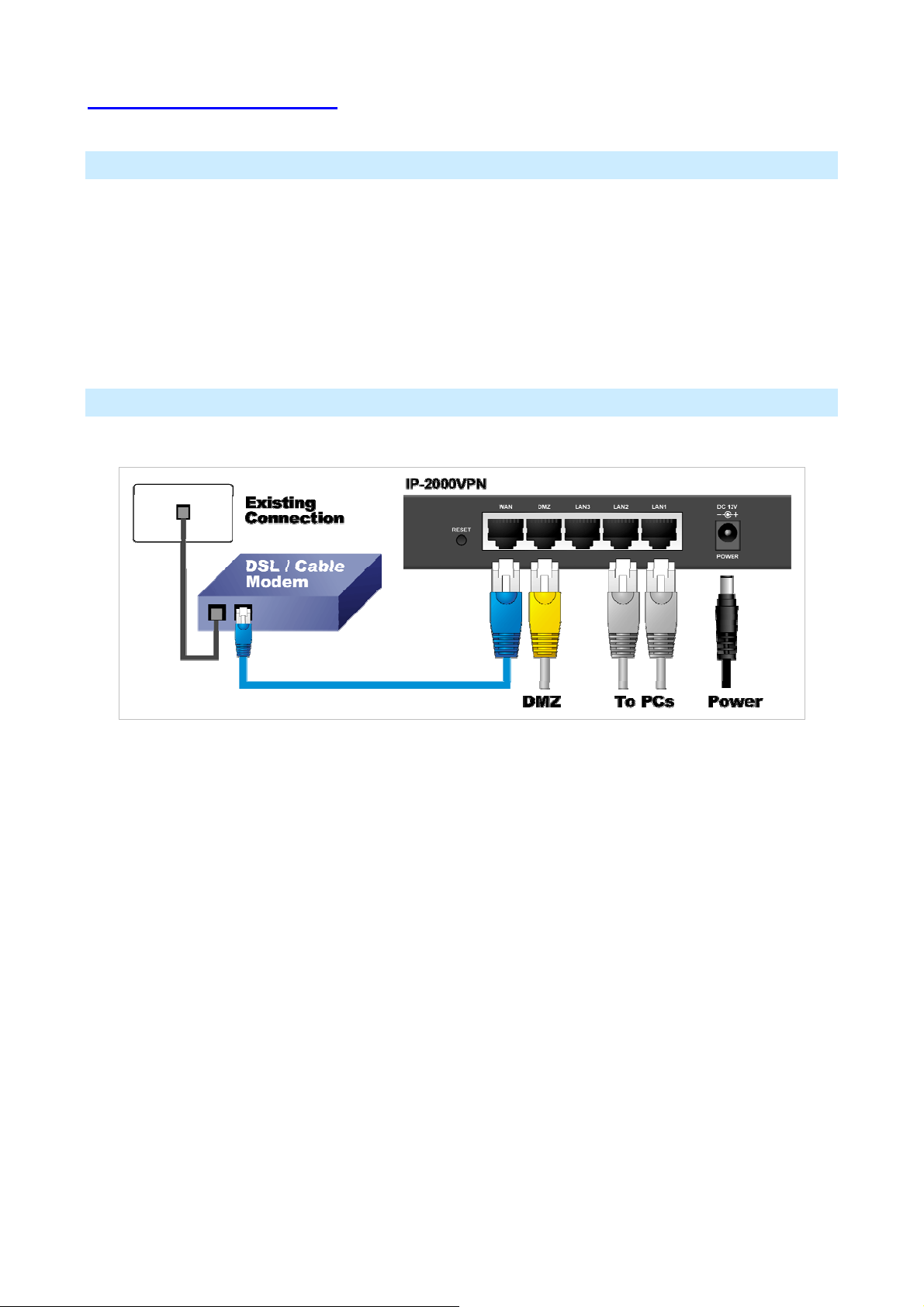
1.2 Installation of the Router
Requirement
• Network cables. Use standard 10/100BaseT network (UTP) cables with RJ45 connectors.
• TCP/IP protocol must be installed on all PCs.
• For Internet Access, an Internet Access account with an ISP, and a Broadband modem (usually, DSL
or Cable modem).
Procedure
1. Choose an Installation Site
Select a suitable place on the network to install the IP-2000VPN. Ensure the IP-2000VPN and the
DSL/Cable modem are powered OFF.
2. Connect LAN Cables
• Use standard LAN cables to connect PCs to the Switching Hub ports on the IP-2000VPN. Both
10BaseT and 100BaseTX connections can be used simultaneously.
• If required, you can connect any LAN port to another Hub. Any LAN port on the IP-2000VPN will
automatically function as an "Uplink" port when required. Just connect any LAN port to a normal port
on the other hub, using a standard LAN cable.
• If desired, connect a PC (server) to the DMZ port. To use multiple servers, use a standard LAN cable
to connect the DMZ port to a normal port on another hub, and connect your servers to the hub. PCs
connected to the DMZ port are isolated from your LAN.
3. Connect WAN Cable
Connect the Broadband modem to the WAN port on the IP-2000VPN. Use the cable supplied with your
Broadband modem. If no cable was supplied, use a standard LAN cable.
AirLive IP-2000VPN User’s Manual
8
Page 12

4. Power Up
• Power on the Broadband modem.
• Connect the supplied power adapter to the IP-2000VPN and power up. Please note that you should
use only the power adapter provided. Using a different one may cause hardware damage.
5. Check the LEDs
• The Power LED should be ON.
• The Status LED should blink during start up, and then turn Off. If it stays on, there is a hardware
error.
• For each LAN (PC) connection, the LAN Link/Act LED should be ON (provided the PC is also ON).
• If a PC is connected to the DMZ port, the DMZ port's Link/Act LED should be ON (provided the PC is
also ON).
• The WAN LED should be ON.
6. Router’s default IP
• The default IP address of router’s LAN port is:
IP Address: 192.168.1.1
Subnet Mask: 255.255.255.0
• For Web Management, please configure client PC as DHCP client to obtain IP address from
IP-2000VPN.
• After configuring the computer’s IP properly, please enter the router’s IP address “192.168.1.1” in
Web browser to manage the router, type the proper user name and password to pass the router’s
authentication.
7. User name and password
• User’s name: admin
• Password: airlive
9
AirLive IP-2000VPN User’s Manual
Page 13
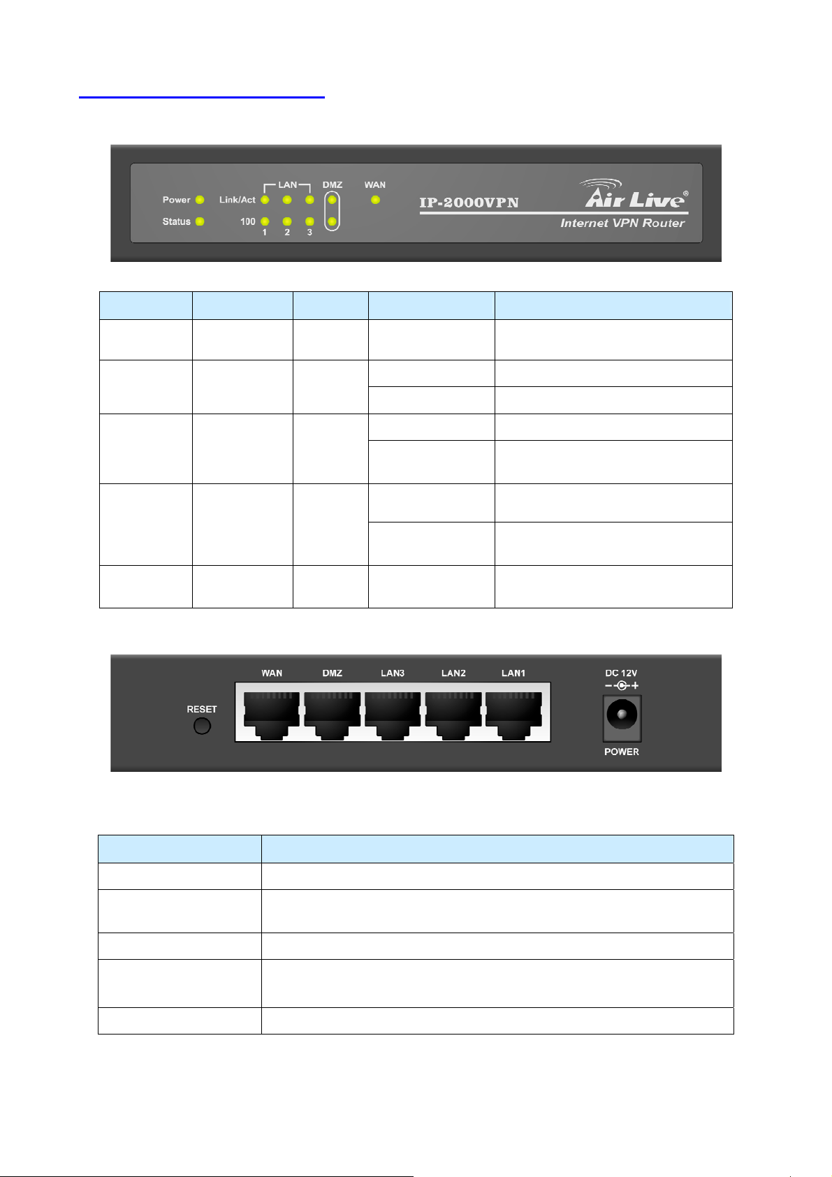
1.3 Front Panel and Rear Panel
LED Function Color Status Description
Power
Power
indication
Status System status ● Red
WAN
Link/Act
(LAN/DMZ)
100
(LAN/DMZ)
WAN port
activity
Link status ● Green
Link rate ● Orange On
● Green On Power on
On Error condition
Blinking System starts up
On The WAN port is linked.
● Green
Blinking
On
Blinking
The WAN port is sending or receiving
data.
An active station is connected to the
corresponding port.
The corresponding LAN port is
sending or receiving data.
Data is transmitting in 100Mbps on
the corresponding port.
Port / Button Description
Power Connect the supplied power adapter (DC12V, 1A ) here.
WAN
The port where you will connect your cable (or xDSL) modem or Ethernet
router
LAN 1 ~ 3 The ports where you will connect networked computers and other devices.
DMZ
PCs or devices connected to the DMZ port are isolated from the LAN.
You can deploy one or more servers to be accessed by Internet users.
Reset Press this button to reset system settings to factory defaults.
AirLive IP-2000VPN User’s Manual
10
Page 14

1.4 Packing List
The following items should be included:
• IP-2000VPN Internet VPN Router
• Installation CD-ROM
• Quick Installation Guide
• AC Adapter
When you open your package, make sure all of the above items are included and not damaged. If you
see that any components are damaged, please notify your dealer immediately.
1.5 Hardware DMZ
Using the DMZ Port
The DMZ port is intended for connection of a server you wish to make available to the public. To use multiple
servers, use a standard LAN cable to connect the DMZ port to a normal port on another switch, and connect
your servers to the switch.
Please note the following points regarding the DMZ port:
• Although physically attached to the switch ports, the DMZ port is not part of the built-in switch. It is a
separate single port which is isolated from the switch.
• PCs connected to the DMZ port are on the same LAN segment as PCs connected to the LAN ports.
They must use the same IP address range.
• PCs connected to the DMZ port are NOT visible to PCs on the LAN ports. So you cannot use
Microsoft networking or other networking protocols to connect to PCs on the DMZ. The connection
must be made via the Internet.
• PCs connected to the DMZ port still share the WAN port IP address for Internet access.
• To make PCs on the DMZ port available from the Internet, the "Virtual Server" (Port Forwarding)
feature must be configured to send incoming traffic to the appropriate server.
Advantages of the DMZ Port
If running any Servers on your LAN, you should connect them to the DMZ port, for the following reasons:
• Traffic passing between the DMZ and LAN passes through the firewall. The firewall will protect your
LAN if your Server is compromised and used to launch an attack on your LAN.
• When using the Virtual Servers feature, a firewall rule to allow incoming traffic from the Internet to the
DMZ is automatically created. If the Server is connected to the LAN ports, you must add the firewall
rule manually.
11
AirLive IP-2000VPN User’s Manual
Page 15

C
h
a
p
t
e
r
2
e
D
p
l
o
y
m
e
n
t
C
h
a
p
t
e
r
2
D
e
p
l
o
y
C
h
a
p
t
e
r
2
D
e
Overview
This chapter describes the setup procedure for:
• Internet Access
• LAN configuration
PCs on your local LAN may also require configuration. For details, see Appendix A - PC Configuration.
Other configuration may also be required, depending on which features and functions of the IP-2000VPN you
wish to use. Use the table below to locate detailed instructions for the required functions.
To Do this: Refer to:
Configure PCs on your LAN. Appendix A:
p
m
l
o
y
m
e
n
t
e
n
t
PC Configuration
Use any of the following Internet features:
• WAN Port
• Advanced Setup
• Dynamic DNS
• Virtual Servers
• Options
Change any of the following Security-related settings:
• Admin Login
• Access Control
• Firewall Rules
• Logs
• E-mail
• Security Options
• Scheduling
• Services
Use the IPSec VPN features:
• VPN Policies
Chapter 4:
Internet Features
Chapter 5:
Security
Chapter 6:
VPN (IPSec)
• Certificates
• CRLs
• VPN Status
Use the Microsoft VPN feature:
• PPTP Server in the IP-2000VPN.
• User and Client setup.
• Checking VPN connection Status.
Check IP-2000VPN Status. Chapter 9:
AirLive IP-2000VPN User’s Manual
Chapter 8:
Microsoft VPN
Status
12
Page 16

Configure or use any of the following:
Chapter 10:
• Configuration File backup and restore.
• Network Diagnostic
• PC Database
• Remote Administration
• Routing
• Upgrade Firmware
• UPnP
Other Features and
Settings
Configuration Program
The IP-2000VPN contains an HTTP server. This enables you to connect to it, and configure it using your Web
Browser. Your Browser must support JavaScript. The configuration program has been tested on the
following browsers:
• Netscape v4.08 or later
• Internet Explorer v4 or later
Preparation
Before attempting to configure the IP-2000VPN, please ensure that:
• Your PC can establish a physical connection to the IP-2000VPN. The PC and the IP-2000VPN must
be directly connected (using the switch ports on the IP-2000VPN) or on the same LAN segment.
• The IP-2000VPN must be installed and powered ON.
• If the IP-2000VPN’s default IP Address (192.168.1.1) is already used by another device, the other
device must be turned OFF until the IP-2000VPN is allocated a new IP Address during configuration.
Using UPnP
If your Windows system supports UPnP, an icon for the IP-2000VPN will appear in the system tray, notifying
you that a new network device has been found, and offering to create a new desktop shortcut to the
newly-discovered device.
• Unless you intend to change the IP Address of the IP-2000VPN, you can accept the desktop
shortcut.
• Whether you accept the desktop shortcut or not, you can always find UPnP devices in My Network
Places (previously called Network Neighborhood).
• Double - click the icon for the IP-2000VPN (either on the Desktop, or in My Network Places) to start
the configuration. Refer to the following section
configuration process.
錯誤! 找不到參照來源。
13
AirLive IP-2000VPN User’s Manual
for details of the initial
Page 17

Using your Web Browser
To establish a connection from your PC to the IP-2000VPN:
1. Start your WEB browser.
2. In the Address box, enter "http://" and the IP Address of the IP-2000VPN, as in this example, which uses
the IP-2000VPN's default IP Address:
3. You will be prompted for a username and password, as shown below.
4. Enter admin for the User name, and airlive for the Password.
5. These are the default values. Both the name and password can (and should) be changed, using the
Admin Login screen. Once you have changed either the name or the password, you must use the
http://192.168.1.1
current values
If you can’t connect
If the IP-2000VPN does not respond, check the following:
• The IP-2000VPN is properly installed, LAN connection is OK, and it is powered ON. You can test the
connection by using the "Ping" command:
• Open the MS-DOS window or command prompt window.
• Enter the command:
ping 192.168.1.1
If no response is received, either the connection is not working, or your PC's IP address is not
compatible with the IP-2000VPN’s IP Address. (See next item).
• If your PC is using a fixed IP Address, its IP Address must be within the range 192.168.1.2 to
192.168.1.254 to be compatible with the IP-2000VPN's default IP Address of 192.168.1.1. Also, the
Network Mask must be set to 255.255.255.0. See Appendix A - PC Configuration for details on
checking your PC's TCP/IP settings.
Ensure that your PC and the IP-2000VPN are on the same network segment. (If you don't have a router, this
must be the case.)
AirLive IP-2000VPN User’s Manual
14
Page 18
C
h
a
p
t
e
r
3
C
n
o
f
i
g
u
r
e
R
o
u
t
e
C
h
a
p
t
e
r
3
C
o
n
f
i
g
u
r
e
C
h
a
p
t
e
r
3
C
o
n
f
i
g
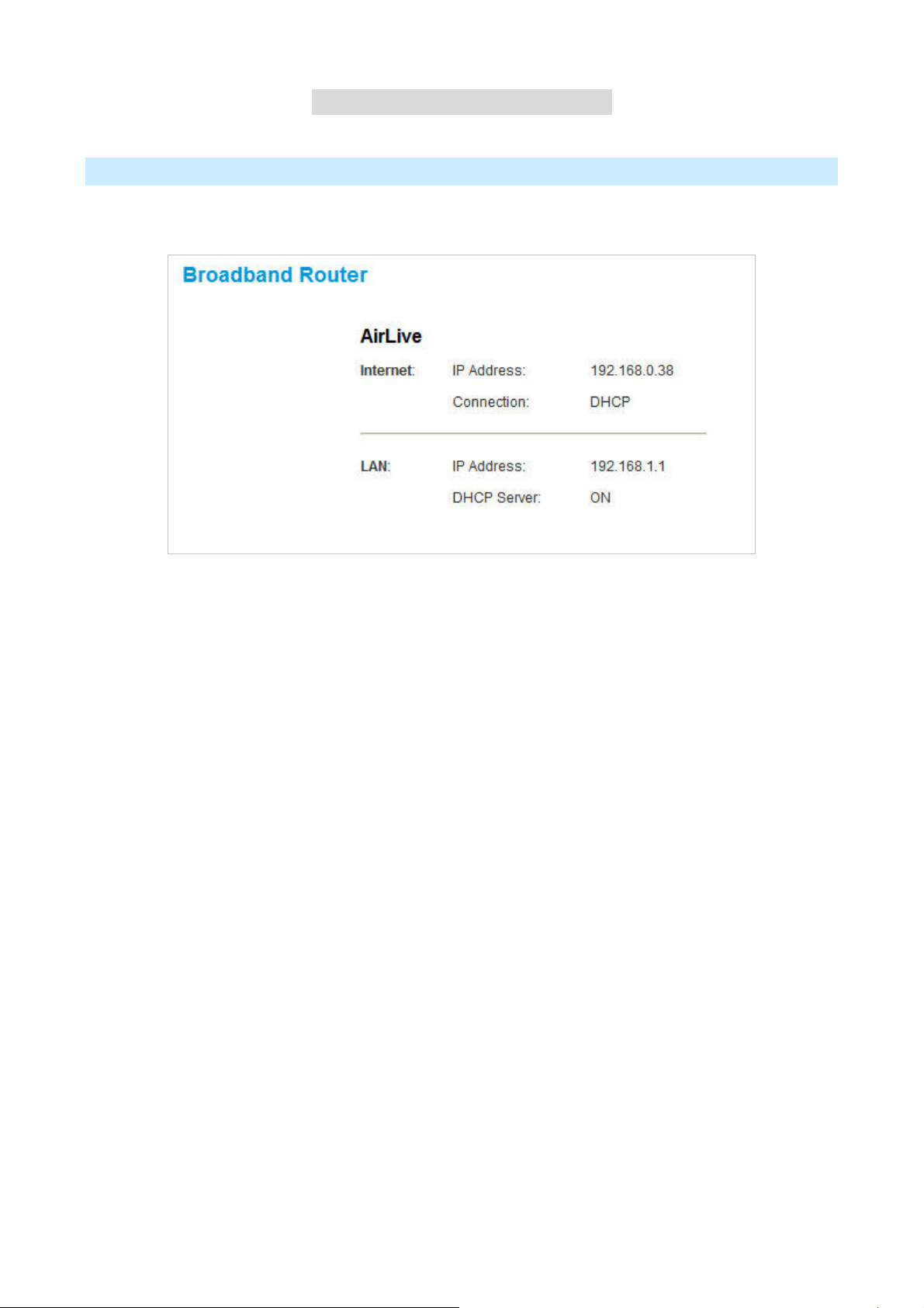
Home Screen
The first time you connect to the IP-2000VPN, you will see the Home screen shown below:
• Use the menu bar on the top of the screen, and the "Back" button on your Browser, for navigation.
u
R
r
e
R
o
o
u
u
r
t
e
r
t
e
r
• Changing to another screen without clicking "Save" does NOT save any changes you may have
made. You must "Save" before changing screens or your data will be ignored.
• On each screen, clicking the "Help" button will display help for that screen.
• From any help screen, you can access the list of all help files (help index).
15
AirLive IP-2000VPN User’s Manual
Page 19

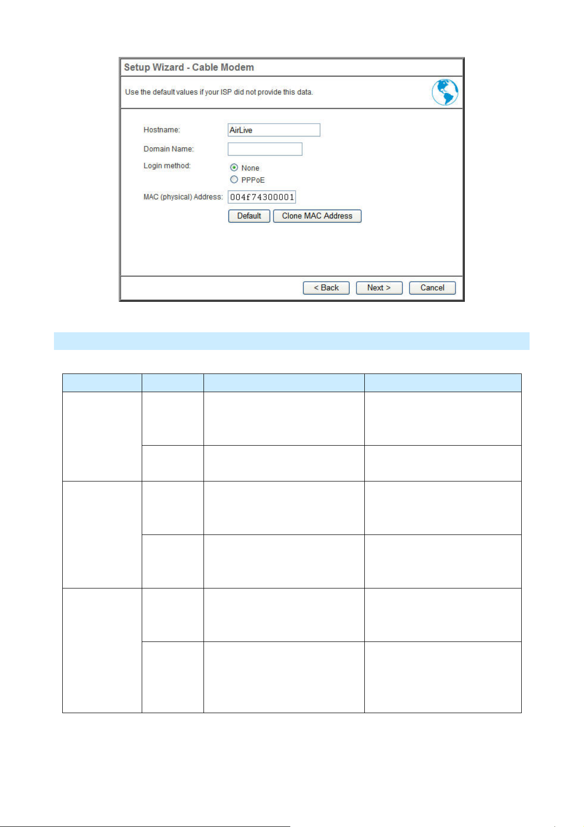
3.1 Setup Wizard
The main purpose of Setup Wizard works to configure WAN type, when you finish the WAN port’s
configuration, you can make the test in the wizard to verify the setting.
• You need to know the type of Internet connection service used by your ISP. Check the data supplied
by your ISP.
• The common connection types are explained in the tables below:
Cable Modem
Login method Type Details ISP Data required
None
Dynamic IP
Address
Static IP
Address
Dynamic IP
Address
Static IP
Address
Your IP Address is
allocated automatically,
when you connect to
you ISP.
Your ISP allocates a
permanent IP Address
to you.
Your IP Address is
allocated automatically,
when you connect to
you ISP.
Your ISP allocates a
permanent IP Address
to you.
Usually, none.
However, some ISP's may require you to
use a particular Hostname, Domain
name, or MAC (physical) address.
IP Address, mask, gateway and DNS
address allocated to you.
Some ISP's may also require you to use a
particular Hostname, Domain name, or
MAC (physical) address.
User name and password. PPPoE
User name and password.
IP Address, mask, gateway and DNS
address allocated to you.
Some ISP's may also require you to use a
AirLive IP-2000VPN User’s Manual
particular Hostname, Domain name, or
MAC (physical) address.
16
Page 20
DSL Modem
Login method Type Details ISP Data required
PPTP
L2TP
Dynamic IP
Address
Static IP
Address
Dynamic IP
Address
Static IP
Address
Dynamic IP
Address
Static IP
Address
Your IP Address is allocated
automatically, when you connect
to you ISP.
Your ISP allocates a permanent IP
Address to you.
You connect to the ISP only when
required. The IP address is usually
allocated automatically.
Your ISP allocates a permanent IP
Address to you.
You connect to the ISP only when
required. The IP address is usually
allocated automatically.
Your ISP allocates a permanent IP
Address to you.
User name and password. PPPoE
IP Address, mask, gateway and
DNS address allocated to you.
• PPTP Server IP Address.
• User name and password.
• PPTP Server IP Address.
• User name and password.
• IP Address allocated to you
• L2TP Server IP Address or
domain name.
• User name and password.
• L2TP Server IP Address or
domain name
17
• User name and password.
• IP Address allocated to you.
AirLive IP-2000VPN User’s Manual
Page 21

None
Dynamic IP
You connect to the ISP only when
Usually, none.
Address
Static IP
Address
required. The IP address is usually
allocated automatically.
Your ISP allocates a permanent IP
Address to you.
IP Address, mask, gateway and
DNS address allocated to you.
Telstra Big Pond Cable (Australia)
Type Details ISP Data required
Dynamic IP
Address
Static IP Address Your ISP allocates a permanent
Your IP Address is allocated
automatically, when you
connect to you ISP.
IP Address to you.
• Big Pond Server IP Address.
• User name and password.
• Big Pond Server IP Address.
• User name and password.
• IP Address allocated to you.
AirLive IP-2000VPN User’s Manual
18
Page 22

SingTel RAS
For this connection method, the following data is required:
• User Name
• Password
• RAS Plan
19
AirLive IP-2000VPN User’s Manual
Page 23
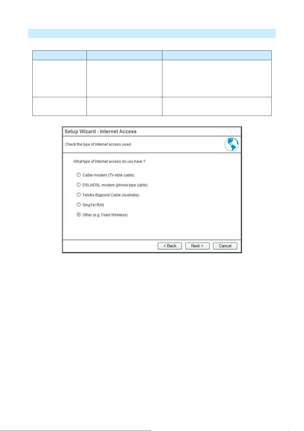
Others (e.g. Fixed Wireless)
Type Details ISP Data required
Dynamic IP Address Your IP Address is allocated
automatically, when you
connect to you ISP.
Static IP Address Your ISP allocates a
permanent IP Address to you.
Usually, none.
However, some ISP's may require you to use
a particular Hostname, Domain name, or
MAC (physical) address.
IP Address, mask, gateway and DNS address
allocated to you.
AirLive IP-2000VPN User’s Manual
20
Page 24

3.2 LAN
Use the LAN link on the main menu to reach the LAN screen. An example screen is shown below.
Data - LAN Screen
TCP/IP
IP Address
Subnet Mask
DHCP Server
IP address for the IP-2000VPN, as seen from the local LAN. Use the
default value unless the address is already in use or your LAN is using a
different IP address range. In the latter case, enter an unused IP
Address from within the range used by your LAN.
The default value 255.255.255.0 is standard for small (class "C")
networks. For other networks, use the Subnet Mask for the LAN
segment to which the IP-2000VPN is attached (the same value as the
PCs on that LAN segment).
• If enabled, the IP-2000VPN will allocate IP Addresses to PCs
(DHCP clients) on your LAN when they start up. The default (and
recommended) value is Enabled.
• If you are already using a DHCP Server, this setting must be
disabled, and the existing DHCP server must be re-configured to
treat the IP-2000VPN as the default Gateway. See the following
section for further details.
• The Start IP Address and Finish IP Address fields set the values
used by the DHCP server when allocating IP Addresses to DHCP
Buttons
Save
Cancel
clients. This range also determines the number of DHCP clients
supported.
See the following section for further details on using DHCP.
Save the data on screen.
The "Cancel" button will discard any data you have entered and reload
the file from the IP-2000VPN.
21
AirLive IP-2000VPN User’s Manual
Page 25

What DHCP Server Can Do
A DHCP (Dynamic Host Configuration Protocol) Server allocates a valid IP address to a DHCP Client (PC or
device) upon request.
• The client request is made when the client device starts up (boots).
• The DHCP Server provides the Gateway and DNS addresses to the client, as well as allocating an IP
Address..
• The IP-2000VPN can act as a DHCP server.
• Windows 2000/XP and other non-Server versions of Windows will act as a DHCP client. This is the
default Windows setting for the TCP/IP network protocol. However, Windows uses the term Obtain
an IP Address automatically instead of "DHCP Client”.
• You must NOT have two (2) or more DHCP Servers on the same LAN segment. (If your LAN does
not have other Routers, this means there must only be one (1) DHCP Server on your LAN).
Using the IP-2000VPN’s DHCP Server
This is the default setting. The DHCP Server settings are on the LAN screen. On this screen, you can:
• Enable or Disable the IP-2000VPN's DHCP Server function.
• Set the range of IP Addresses allocated to PCs by the DHCP Server function.
You can assign Fixed IP Addresses to some devices while using DHCP, provided that the Fixed
IP Addresses are NOT within the range used by the DHCP Server.
Using another DHCP Server
You can only use one (1) DHCP Server per LAN segment. If you wish to use another DHCP Server, rather
than the IP-2000VPN's, the following procedure is required.
• Disable the DHCP Server feature in the IP-2000VPN. This setting is on the LAN screen.
• Configure the DHCP Server to provide the IP-2000VPNs IP Address as the Default Gateway .
To Configure your PCs to use DHCP
This is the default setting for TCP/IP under Windows 98/ME/2000/XP or else operating system.
See Appendix A - Client Configuration for the procedure to check these settings.
AirLive IP-2000VPN User’s Manual
22
Page 26

Operation
Once both the IP-2000VPN and the PCs are configured, operation is automatic.
However, there are some situations where additional Internet configuration may be required:
• If using Internet-based Communication Applications, it may be necessary to specify which PC
receives an incoming connection. Refer to Chapter 4 - Internet Features for further details.
• Applications which use non-standard connections or port numbers may be blocked by the
IP-2000VPN's built-in firewall. You can define such applications as Special Applications to allow
them to function normally. Refer to Chapter 4 - Internet Features for further details.
• Some non-standard applications may require use of the DMZ feature. Refer to Chapter 4 - Internet
Features for further details.
23
AirLive IP-2000VPN User’s Manual
Page 27
C
h
a
p
t
e
r
p
p
4
t
e
r
t
e
r
C
h
a
C
h
a
4.1 WAN Port
Overview
The following advanced features are provided.
• WAN Port Configuration
• Advanced Internet
• Communication Applications
• Special Applications
• Multi-DMZ
• URL filter
• Dynamic DNS
• Virtual Servers
I
n
t
e
r
e
n
t
F
e
a
t
u
r
e
4
I
n
t
e
r
n
e
t
F
e
4
I
n
t
e
r
n
e
a
t
F
e
a
s
t
u
r
e
s
t
u
r
e
s
• Options
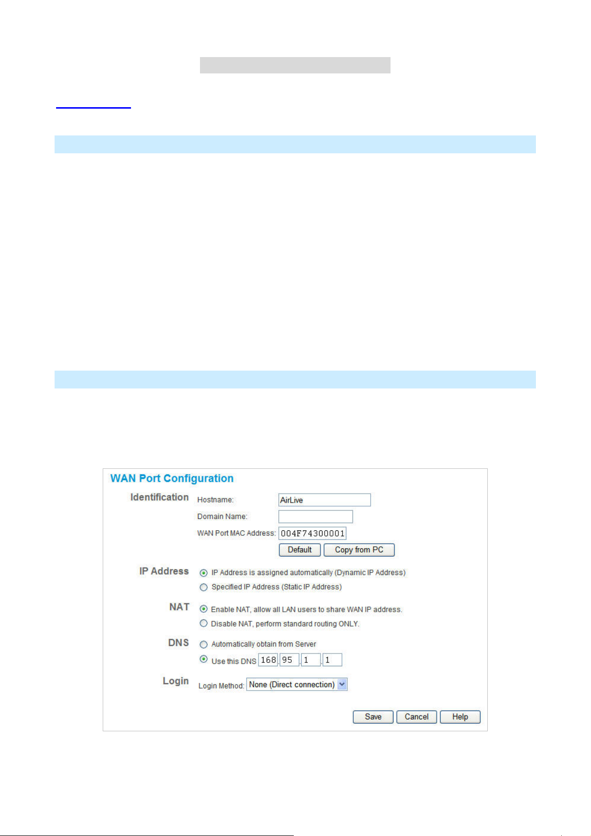
WAN Port Configuration
The WAN Port Configuration screen provides an alternative to using the Wizard. It can be accessed from the
Internet menu. An example screen is shown below.
AirLive IP-2000VPN User’s Manual
24
Page 28

Data – WAN Port Configuration Screen
Identification
Hostname
Domain name
MAC Address
IP Address
IP Address is assigned
automatically
Specified
Normally, there is no need to change the default name, but if your ISP
requests that you use a particular “Hostname”, enter it here.
If your ISP provided a domain name, enter it here. Otherwise, it can be left
blank.
Also called Network Adapter Address or Physical Address. This is a
low-level identifier, as seen from the WAN port.
Normally there is no need to change this, but some ISPs require a
particular value, often that of the PC initially used for Internet access.
You can use the Copy from PC button to copy your PC's address into this
field, the Default button to insert the default value, or enter a value directly.
Also called Dynamic IP Address. This is the default, and the most
common.
Leave this selected if your ISP allocates an IP Address to the IP-2000VPN
upon connection.
Also called Static IP Address. Select this if your ISP has allocated you a
IP Address
NAT
Enable NA T
Disable NAT Disabling NAT will disable Internet access, unless all PCs have valid
fixed IP Address. If this option is selected, the following data must be
entered.
• IP Address.
The IP Address allocated by the ISP.
• Network Mask (Not required for PPPoE)
This is also supplied by your ISP. It must be compatible with the IP
Address above.
• Gateway IP Address (Not required for PPPoE)
The address of the router or gateway, as supplied by your ISP.
NAT (Network Address Translation) is the technology which allows all PCs
on your LAN to share the Internet IP address allocated to the WAN port on
this Router. From the Internet, all PCs appear to have the same IP
address.
For normal operation, this setting must be ENABLED.
Internet IP addresses.
If you wish to use this device for Routing ONLY (and NOT for Internet
access), then NAT should be disabled.
25
AirLive IP-2000VPN User’s Manual
Page 29

DNS
Automatically obtain
from Server
Use this DNS
Login
Login Method
The DNS (Domain Name Server) address will be obtained automatically
from your ISP's server. Note that if using a fixed IP address, with no login
(login is set to "None"), then no Server is used, and this option cannot be
used.
If this option is selected, you must enter the IP address of the DNS
(Domain Name Server) you wish to use.
Note: If the DNS is unavailable, the "Backup DNS", entered on the
Internet - Options screen, will be used.
If your ISP does not use a login method (username, password) for Internet
access, leave this at the default value "None (Direct connection)"
Otherwise, check the documentation from your ISP, select the login
method used, and enter the required data.
• PPPoE - this is the most common login method, widely used with DSL
modems. Normally, your ISP will have provided some software to
connect and login. This software is no longer required, and should not
Login User Name
Login Password
RAS Plan
Server Address
Connection behavior
be used.
• PPTP - this is mainly used in Europe. You need to know the PPTP
Server address as well as your name and password.
• L2TP - You need to know the L2TP Server address as well as your
name and password.
• Big Pond Cable - for Australia only.
• SingTel RAS - for Singapore only.
The User Name (or account name) provided by your ISP.
Enter the password for the login name above.
For SingTel customers only, select the RAS plan you are on.
If using PPTP, L2TP or Big Pond Cable, enter the address of your ISP's
server.
For PPPoE or SingTel RAS, the Server address in not required.
Select the desired option:
• Automatic Connect/Disconnect
An Internet connection is automatically made when required, and
• Manual Connect/Disconnect
• Keep alive (maintain connection)
AirLive IP-2000VPN User’s Manual
disconnected when idle for the time period specified by the
"Auto-disconnect Idle Time-out".
You must manually establish and terminate the connection.
The connection will never be disconnected by this device. If
26
Page 30
disconnected by your ISP, the connection will be re-established
immediately. (However, this does not ensure that your Internet IP
address will remain unchanged.)
Auto-disconnect Idle
Time-out
This field has no effect unless the setting above is Automatic
Connect/Disconnect.
If Auto-disconnect is being used, enter the desired idle time-out period (in
minutes). After the connection to your ISP has been idle for this time
period, the connection will be terminated.
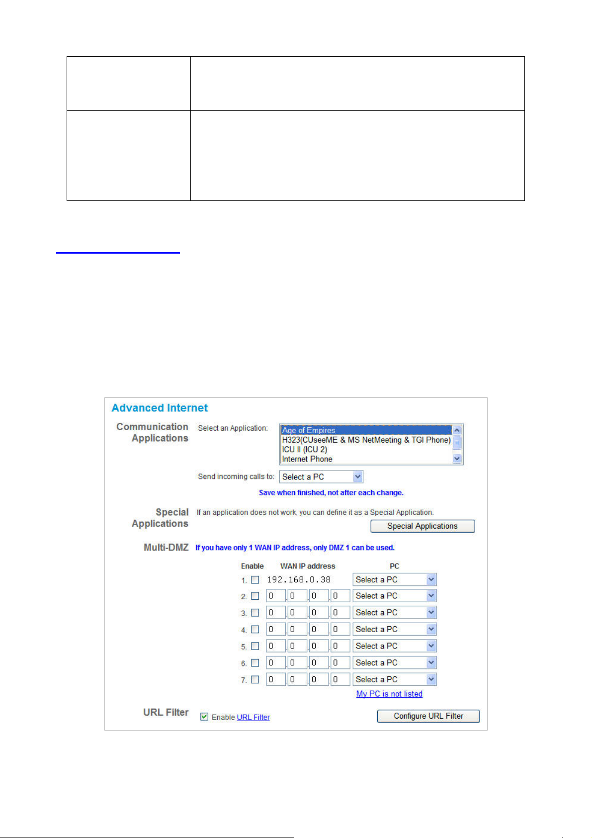
4.2 Advanced Internet
This screen allows configuration of all advanced features relating to Internet access.
• Communication Applications
• Special Applications
• Multi-DMZ
• URL Filter
27
AirLive IP-2000VPN User’s Manual
Page 31

Communication Applications
Most applications are supported transparently by the IP-2000VPN. But sometimes it is not clear which PC
should receive an incoming connection. This problem could arise with the Communication Applications
listed on this screen.
If this problem arises, you can use this screen to set which PC should receive an incoming connection, as
described below.
Communication Applications
Select an Application
Send incoming calls to
This lists applications which may generate incoming connections, where
the destination PC (on your local LAN) is unknown.
This lists the PCs on your LAN.
• If necessary, you can add PCs manually, using the PC Database
option on the Other menu.
• For each application listed above, you can choose a destination PC.
• There is no need to "Save" after each change; you can set the
destination PC for each application, then click "Save".
Special Applications
If you use Internet applications with non-standard connections or port numbers, you may find that they do not
function correctly because they are blocked by the IP-2000VPN's firewall. In this case, you can define the
application as a "Special Application".
Special Applications Screen
This screen can be reached by clicking the Special Applications button on the Advanced Internet screen.
You can then define your Special Applications. You will need detailed information about the application; this is
normally available from the supplier of the application.
Also, note that the terms "Incoming" and "Outgoing" on this screen refer to traffic from the client (PC)
viewpoint.
AirLive IP-2000VPN User’s Manual
28
Page 32

Data – Special Applications Screen
Special Applications
Checkbox
Name
Incoming Ports
Outgoing Ports
Use this to Enable or Disable this Special Application as required.
Enter a descriptive name to identify this Special Application.
• Type - Select the protocol (TCP or UDP) used when you receive data from the
special application or service. (Note: Some applications use different protocols
for outgoing and incoming data).
• Start - Enter the beginning of the range of port numbers used by the application
server, for data you receive. If the application uses a single port number, enter
it in both the "Start" and "Finish" fields.
• Finish - Enter the end of the range of port numbers used by the application
server, for data you receive.
• Type - Select the protocol (TCP or UDP) used when you send data to the
remote system or service.
• Start - Enter the beginning of the range of port numbers used by the application
server, for data you send to it. If the application uses a single port number,
enter it in both the "Start" and "Finish" fields.
• Finish - Enter the end of the range of port numbers used by the application
server, for data you send to it. If the application uses a single port number,
enter it in both the "Start" and "Finish" fields.
Using a Special Application
• Configure the Special Applications screen as required.
• On your PC, use the application normally. Remember that only one (1) PC can use each Special
application at any time. Also, when 1 PC is finished using a particular Special Application, there may
need to be a "Time-out" before another PC can use the same Special Application. The "Time-out"
period may be up to 3 minutes
If an application still cannot function correctly, try using the "DMZ" feature.
Multi-DMZ
This feature, if enabled, allows one (1) or more computers on your LAN to be exposed to all users on the
Internet. You can set a DMZ PC for each WAN IP address. If you only have 1 WAN IP addresses, only 1 DMZ
PC can be used.
29
AirLive IP-2000VPN User’s Manual
Page 33

This allows unrestricted 2-way communication between the "DMZ PC" and other Internet users or Servers.
• This allows almost any application to be used on the "DMZ PC".
• The "DMZ PC" will receive all "Unknown" connections and data.
• If the DMZ feature is enabled, you must select the PC to be used as the "DMZ PC".
• To use more than one (1) DMZ, your ISP must assign multiple fixed IP addresses to you. You must
enter each IP address; you can then assign a DMZ PC for each IP address.
The "DMZ PC" is effectively outside the Firewall, making it more vulnerable to attacks. For this
reason, you should only enable the DMZ feature when required.
URL Filter
The URL Filter allows you to block access to undesirable Web site.
• To use this feature, you must define "filter strings". If the "filter string" appears in a requested URL,
the request is blocked.
• Enabling the URL Filter also affects the Internet Access Log. If Enabled, the "Destination" field in
the log will display the URL. Otherwise, it will display the IP Address
• The URL Filter can be Enabled or Disabled on the Advanced Internet screen
URL Filter Screen
Click the "Configure URL Filter" button on the Advanced Internet screen to access the URL Filter screen. An
example screen is shown below.
AirLive IP-2000VPN User’s Manual
30
Page 34

Data – URL Filter Screen
Filter Strings
Current Entries
This lists any existing entries. If you have not entered any values, this list will be
empty.
Add Filter String
To add an entry to the list, enter it here, and click the "Add" button.
An entry may be a Domain name (e.g. www.trash.com) or simply a string.
(e.g. ads/ ). Any URL which contains ANY entry ANYWHERE in the URL will be
blocked.
Buttons
Delete/Delete All
Use these buttons to delete the selected entry or all entries, as required. Multiple
entries can be selected by holding down the CTRL key while selecting. (On the
Macintosh, hold the SHIFT key while selecting.)
Add
Use this to add the current Filter String to the site list.
4.3 Dynamic DNS
This free service is very useful when combined with the Virtual Server feature. It allows Internet users to
connect to your Virtual Servers using a URL, rather than an IP Address.
This also solves the problem of having a dynamic IP address. With a dynamic IP address, your IP address
may change whenever you connect, which makes it difficult to connect to you.
The Service works as follows:
1. You must register for the service at one of the listed DDNS Service providers.
2. After registration, follow the Service Provider's procedure to request a Domain Name, and have it
allocated to you.
3. Enter your DDNS data on the IP-2000VPN's DDNS screen (shown below).
4. The IP-2000VPN will then automatically ensure that your current IP Address is recorded and updated at
the DDNS server.
If the DDNS Service provides software to perform this "IP address update"; you should disable the
"Update" function, or not use the software at all.
5. From the Internet, users will be able to connect to your Virtual Servers (or DMZ PC) using your Domain
name, as shown on this screen.
31
AirLive IP-2000VPN User’s Manual
Page 35

Dynamic DNS Screen
Select Internet on the main menu, then Dynamic DNS, to see a screen like the following:
Data – Dynamic DNS Screen
DDNS Service
DDNS Service
DDNS Data
DDNS Service
User Name
Password/Key
• You must register for the service at one of the listed Service Providers. You
can reach the Service provider's Web Site by selecting them in the list and
clicking the "Web Site" button.
• Apply for a Domain Name, and ensure it is allocated to you.
• Details of your DDNS account (Name, password, Domain name) must then be
entered and saved on this screen.
• This device will then automatically ensure that your current IP Address is
recorded by the DDNS Service Provider. (You do NOT need to use the "Client"
program provided by some DDNS Service providers.)
• From the Internet, users will now be able to connect to your Virtual Servers (or
DMZ PC) using your Domain name.
Select the desired DDNS Service provider.
Enter your Username for the DDNS Service.
Enter your current password for the DDNS Service.
Domain Name
DDNS Status
AirLive IP-2000VPN User’s Manual
Enter the domain name allocated to you by the DDNS Service. If you have more
than one name, enter the name you wish to use.
• This message is returned by the DDNS Server
• Normally, this message should be something like "Update successful" or "IP
address updated".
• If the message indicates some problem, you need to connect to the DDNS
Service provider and correct this problem.
32
Page 36

4.4 Virtual Server
This feature allows you to make Servers on your LAN accessible to Internet users. Normally, Internet users
would not be able to access a server on your LAN because:
• Your Server does not have a valid external IP Address.
• Attempts to connect to devices on your LAN are blocked by the firewall in this device.
The "Virtual Server" feature solves these problems and allows Internet users to connect to your servers, as
illustrated below.
IP address seen by Internet Users
Note that, in this illustration, both Internet users are connecting to the same IP Address, but using different
protocols.
To Internet users, all virtual Servers on your LAN have the same IP Address. This IP Address is
allocated by your ISP.
This address should be static, rather than dynamic, to make it easier for Internet users to connect to your
Servers.
However, you can use the DDNS (Dynamic DNS) feature to allow users to connect to your Virtual Servers
using a URL, instead of an IP Address.
33
AirLive IP-2000VPN User’s Manual
Page 37

Using the DMZ port for Virtual Servers
You should connect your Virtual Servers to the DMZ port, for the following reasons:
• Traffic passing between the DMZ and LAN passes through the firewall. The firewall will protect your
LAN if your Server is compromised and used to launch an attack on your LAN.
• For each enabled Virtual Server, a firewall rule to allow incoming traffic from the Internet (WAN) to the
DMZ is automatically created. If the Server is connected to the LAN (switch) ports, you must add the
firewall rule manually.
The DMZ port is a normal port, not an "uplink" port. If connecting to a switch, connect to the
standard port on the switch.
Virtual Server Screen
The Virtual Servers screen is reached by the Virtual Servers link on the Internet menu. An example screen
is shown below.
This screen lists a number of pre-defined Servers, providing a quick and convenient method to set up the
common server types.
AirLive IP-2000VPN User’s Manual
34
Page 38

Data – Virtual Servers Screen
Servers
Servers
Properties
Enable
PC (Server)
This lists a number of pre-defined Servers, plus any Servers you have defined.
Details of the selected Server are shown in the "Properties" area.
Use this to Enable or Disable support for this Server, as required.
• If Enabled, any incoming connections will be forwarded to the selected PC.
• If Disabled, any incoming connection attempts will be blocked.
Select the PC for this Server. The PC must be running the appropriate Server
software.
Defining your own Virtual Servers
If the type of Server you wish to use is not listed on the Virtual Servers screen, you can use the Firewall
Rules to allow particular incoming traffic and forward it to a specified PC (Server).
Connecting to the Virtual Servers
Once configured, anyone on the Internet can connect to your Virtual Servers. They must use the Internet IP
Address (the IP Address allocated to you by your ISP).
e.g.
http://203.70.212.52
ftp://203.70.212.52
It is more convenient if you are using a Fixed IP Address from your ISP, rather than Dynamic. However, you
can use the Dynamic DNS feature, described in the following section, to allow users to connect to your Virtual
Servers using a URL, rather than an IP Address.
35
AirLive IP-2000VPN User’s Manual
Page 39

4.5 Options
This screen allows advanced users to enter or change a number of settings. For normal operation, there is no
need to use this screen or change any settings.
Data – Options Screen
Backup DNS
IP Address
MTU
MTU size
Enter the IP Address of the DNS (Domain Name Servers) here. These DNS will be
used only if the primary DNS is unavailable.
MTU (Maximum Transmission Unit) value should only be changed if advised to do so
by Technical Support.
• Enter a value between 1 and 1500.
• This device will still auto-negotiate with the remote server, to set the MTU size.
The smaller of the 2 values (auto-negotiated, or entered here) will be used.
• For direct connections (not PPPoE or PPTP), the MTU used is always 1500.
AirLive IP-2000VPN User’s Manual
36
Page 40

C
h
a
p
t
e
r
p
p
t
e
r
t
e
r
C
h
a
C
h
a
Overview
The following advanced configurations are provided.
• Admin Login
• Access Control
• Firewall Rules
• Logs
• E-mail
• Security Options
• Scheduling
• Services
5
S
e
c
u
r
i
t
y
5
S
e
5
c
S
e
c
u
u
r
i
t
y
r
i
t
y
5.1 Admin Login
The Admin Login screen allows you to assign a user name and password to the IP-2000VPN.
1. The default login name is "admin". Change this to the desired value.
2. The default password is airlive. Enter the desired password in the New Password and Verify Password
fields.
3. Save your changes.
You will see a login prompt when you connect to the IP-2000VPN, as shown below.
37
AirLive IP-2000VPN User’s Manual
Page 41

Enter the "User Name" and "Password" you set on the Admin Login screen above.
AirLive IP-2000VPN User’s Manual
38
Page 42

5.2 Access Control
This feature is accessed by the Access Control link on the Security menu.
The Access Control feature allows administrators to restrict the level of Internet Access available to PCs on
your LAN. With the default settings, everyone has unrestricted Internet access.
To use this feature
1. Set the desired restrictions on the "Default" group. All PCs are in the "Default" group unless explicitly
moved to another group.
2. Set the desired restrictions on the other groups ("Group 1", "Group 2", "Group 3" and "Group 4") as
needed.
3. Assign PC to the groups as required.
Restrictions are imposed by blocking "Services", or types of connections. All common Services
are pre-defined. If required, you can also define your own Services.
Access Control Screen
To view this screen, select the Access Control link on the Security menu.
39
AirLive IP-2000VPN User’s Manual
Page 43

Data – Access Control Screen
Group
Group
"Members" Button
Internet Access
Restrictions
Select the desired Group. The screen will update to display the settings for the
selected Group. Groups are named "Default", "Group 1", "Group 2", "Group 3"
and "Group 4", and cannot be re-named.
Click this button to add or remove members from the current Group.
• If the current group is "Default", then members can not be added or deleted.
This group contains PCs not allocated to any other group.
• To remove PCs from the Default Group, assign them to another Group.
• To assign PCs to the Default Group, delete them from the Group they are
currently in.
See the following section for details of the Group Members screen.
Select the desired options for the current group:
• None - Nothing is blocked. Use this to create the least restrictive group.
• Block all Internet access - All traffic via the WAN port is blocked. Use this to
create the most restrictive group.
• Block selected Services - You can select which Services are to block. Use
Block by Schedule
Services
Buttons
Members
Save
Cancel
View Log
this to gain fine control over the Internet access for a group.
If Internet access is being blocked, you can choose to apply the blocking only
during scheduled times. (If access is not blocked, no Scheduling is possible, and
this setting has no effect.)
To define the schedule, use the Schedule option on the menu.
This lists all defined Services. Select the Services you wish to block. To select
multiple services, hold the CTRL key while selecting. (On the Macintosh, hold the
SHIFT key rather than CTRL.)
Click this button to add or remove members from the current Group.
If the current group is "Default", then members can not be added or deleted. This
group contains PCs not allocated to any other group.
See the following section for details of the Group Members screen.
Save the data on screen.
Reverse any changes made since the last "Save".
Click this to open a sub-window where you can view the "Access Control" log.
This log shows attempted Internet accesses which have been blocked by the
Access Control feature.
Clear Log
AirLive IP-2000VPN User’s Manual
Click this to clear and restart the "Access Control" log, making new entries easier
to read.
40
Page 44

Group Members Screen
This screen is displayed when the Members button on the Access Control screen is clicked.
Use this screen to add or remove members (PCs) from the current group.
• The "Del >>" button will remove the selected PC (in the Members list) from the current group.
• The "<< Add" button will add the selected PC (in the Other PCs list) to the current group.
PCs not assigned to any group will be in the "Default" group. PCs deleted from any other Group
will be added to the "Default" group.
Access Control Log
To check the operation of the Access Control feature, an Access Control Log is provided. Click the View
Log button on the Access Control screen to view this log.
This log shows attempted Internet accesses which have been blocked by the Access Control function.
Data shown in this log is as follows:
Access Control Log
Date/Time
Name
Source IP address
Date and Time of the attempted access.
If known, the name of the PC whose access was blocked. This name is taken
from the Network Clients database
The IP Address of the PC or device whose access request was blocked
MAC address
Destination
The hardware or physical address of the PC or device whose access request was
blocked
The destination URL or IP address
41
AirLive IP-2000VPN User’s Manual
Page 45

5.3 Firewall Rule
For normal operation and LAN protection, it is not necessary to use this screen.
The Firewall will always block DoS (Denial of Service) attacks. A DoS attack does not attempt to steal data or
damage your PCs, but overloads your Internet connection so you can not use it - the service is unavailable.
As well, you can use this screen to create Firewall rules to block or allow specific traffic. But incorrect
configuration may cause serious problems.
This feature is for advanced administrators only!
Firewall Rules Screen
Click the Firewall Rules option on the Security menu to see a screen like the following example. This
example contains two (2) rules for outgoing traffic.
Since the default rule for outgoing (LAN => WAN) traffic is "Allow", having an "Allow" rule for
LAN => WAN only makes sense in combination with another rule.
For example, the screen below shows a rule blocking all traffic to a MSN Game Server, followed by
another rule allowing access by a specific PC.
AirLive IP-2000VPN User’s Manual
42
Page 46

Data – Firewall Rules Screen
Rule List
View Rules
for …
Data
Add
Edit
Move
Select the desired option; the screen will update and list any current rules. If you
have not defined any rules, the list will be empty.
For each rule, the following data is shown:
• Name - The name you assigned to the rule.
• Source - The traffic covered by this rule, defined by the source IP address. If the
IP address is followed by ... this indicates there is range of IP addresses, rather
than a single address.
• Destination - The traffic covered by this rule, defined by destination IP address.
If the IP address is followed by ... this indicates there is range of IP addresses,
rather than a single address.
• Action - Action will be "Forward" or "Block"
To add a new rule, click the "Add" button, and complete the resulting screen. See the
following section for more details.
To Edit or modify an existing rule, select it and click the "Edit" button.
There are 2 ways to change the order of rules
• Use the up and down indicators on the right to move the selected rule. You must
Delete
View Log
System Rules
confirm your changes by clicking "OK". If you change your mind before clicking
"OK", click "Cancel" to reverse your changes.
• Click "Move" to directly specify a new location for the selected rule.
To delete an existing rule, select it and click the "Delete" button.
Clicking the "View Log" button will open a new window and display the Firewall log.
Clicking the "System Rules" button will open a new window and display the default
firewall rules currently applied by the system. These rules cannot be edited, but any
rules you create will take precedence over the default rules.
43
AirLive IP-2000VPN User’s Manual
Page 47

Define Firewall Rule
Clicking the "Add" button in the Firewall Rules screen will display a screen like the example below.
AirLive IP-2000VPN User’s Manual
44
Page 48

Data – Define Firewall Rule Screen
Define Firewall Rule
Name
Type
Source IP
Dest IP
Enter a suitable name for this rule.
This determines the source and destination ports for traffic covered by this rule.
Select the desired option.
These settings determine which traffic, based on their source IP address, is
covered by this rule.
Select the desired option:
• Any - All traffic from the source port is covered by this rule.
• Single address - Enter the required IP address in the "Start IP address"
field". You can ignore the "Subnet Mask" field.
• Range address - If this option is selected, you must complete both the "Start
IP address" and "Finish IP address" fields. You can ignore the "Subnet
Mask" field.
• Subnet address - If this option is selected, enter the required mask in the
"Subnet Mask" field.
These settings determine which traffic, based on their destination IP address, is
covered by this rule.
Select the desired option:
Services
Action
Log
• Any - All traffic from the source port is covered by this rule.
• Single address - Enter the required IP address in the "Start IP address"
field". You can ignore the "Subnet Mask" field.
• Range address - If this option is selected, you must complete both the "Start
IP address" and "Finish IP address" fields. You can ignore the "Subnet
Mask" field.
• Subnet address - If this option is selected, enter the required mask in the
"Subnet Mask" field.
Select the desired Service or Services. This determines which packets are
covered by this rule, based on the protocol (TPC or UDP) and port number. If
necessary, you can define a new Service on the "Services" screen, by defining
the protocols and port numbers used by the Service.
Select the desired action for packets covered by this rule:
This determines whether packets covered by this rule are logged. Select the
desired option.
45
AirLive IP-2000VPN User’s Manual
Page 49

5.4 Logs
The Logs record various types of activity on the IP-2000VPN. This data is useful for troubleshooting, but
enabling all logs will generate a large amount of data and adversely affect performance.
Since only a limited amount of log data can be stored in the IP-2000VPN, log data can also be E-mailed to
your PC or sent to a Syslog Server.
AirLive IP-2000VPN User’s Manual
46
Page 50

Data – Logs Screen
Enable Logs
Incoming Traffic
Outgoing Traffic
Select the desired option:
• All IP traffic - this will log all incoming TCP/IP connections, of any type. This
will generate the largest logs, and fill the internal log buffer more quickly.
• All TCP/UDP/ICMP traffic - These 3 protocols are used by most internet traffic.
TCP is used by HTTP, FTP, Telnet, E-mail and other common Internet
protocols and applications. UDP is used by Video streams and other
communications where speed is more important than guaranteed delivery.
ICMP is used by the "ping" and "trace route" applications, and other network
diagnostics.
Select the desired option:
• All IP traffic - - this will log all outgoing TCP/IP connections, of any type. This
will generate the largest logs, and fill the internal log buffer more quickly.
• All TCP/UDP/ICMP traffic - These 3 protocols are used by most internet traffic.
TCP is used by HTTP, FTP, Telnet, E-mail and other common Internet
protocols and applications. UDP is used by Video streams and other
communications where speed is more important than guaranteed delivery.
ICMP is used by the "ping" and "trace route" applications, and other network
diagnostics.
Because most connections are logged, the logs will still be large.
• Selected Traffic only - This selection will reduce the size of the log
considerably. Only HTTP connections are logged. Select the traffic you wish to
include:
• Attempted access to blocked sites - This will only log Web connections
which are blocked by the URL filter.
• Websites and news groups - This logs successful (allowed) connections
to Web Sites and newsgroup servers.
47
AirLive IP-2000VPN User’s Manual
Page 51

System Log
Select the desired option:
• Router operations (start up, get time etc) - This option will log normal Router
operations.
• Connections to the Web - based interface of this Router - This option will
log each connection to the Router itself, whenever the Web-based
management interface is used.
• Other connections and traffic to this Router - This option will log other traffic
sent to the Router itself, such as "pings" or RIP (Router Information Protocol)
packets.
• Known DoS attacks and Port Scans - This will log details of DoS (Denial of
Service) attacks which have been blocked by the built-in Firewall. This Firewall
uses "Stateful Inspection" technology to block packets which are individually
valid, but collectively form an attack. Port scans, where a series of ports are
checked to see if they are opened (available) and also logged.
VPN
View Log Button
Clear Log
Button
Timezone
Timezone
Syslog Server
Enable Syslog
Syslog Server
Include
If enabled, the VPN log will record incoming and outgoing VPN connections.
Use this to view each log, as required.
Use this to restart the required log. This makes it easier to read the latest entries.
Select the correct Timezone for your location. This is required for the date/time
shown on the logs to be correct.
If enabled, log data will be sent to your Syslog Server.
Enter the IP address of your Syslog Server.
Select the logs you wish to be included in the data sent to the Syslog Server.
AirLive IP-2000VPN User’s Manual
48
Page 52

5.5 E-mail
Data – E-mail Screen
E-Mail Alerts
Send E-Mail alert
E-Mail Logs
Send Logs by
E-Mail
Include
Send
If enabled, an E-mail will be sent immediately if a DoS (Denial of Service) attack
is detected. If enabled, the E-mail address information must be provided.
If enabled, logs will be logs to the specified E-mail address. You need to select
the Logs to be E-mailed, and complete the E-mail address settings on this
screen.
Select the log items to be included in the E-mail.
Select the desired option for sending the log by E-mail.
• When log is full - The time is not fixed. The log will be sent when the log is
full, which will depend on the volume of traffic.
• Every day, Every Monday... - The log is sent on the interval specified.
• If "Every day" is selected, the log is sent at the time specified.
• If the day is specified, the log is sent once per week, on the specified
E-mail address
day.
• Select the time of day you wish the E-mail to be sent.
• If the log is full before the time specified to send it, it will be sent
regardless.
Enter the E-mail address the Log is to be sent to. The E-mail will also show this
address as the Sender's address.
49
AirLive IP-2000VPN User’s Manual
Page 53

Subject
Enter the text string to be shown in the "Subject" field for the E-mail.
SMTP Server
Port No.
Enter the address or address or IP address of the SMTP (Simple Mail Transport
Protocol) Server you use for outgoing E-mail.
Enter the port number used to connect to the SMTP Server. The default value is
25.
AirLive IP-2000VPN User’s Manual
50
Page 54

5.6 Security Options
This screen allows you to set Firewall and other security-related options.
Data – Security Options Screen
Firewall
Enable DoS
Firewall
Threshold
If enabled, DoS (Denial of Service) attacks will be detected and blocked. The
default is enabled. It is strongly recommended that this setting be left enabled.
Note:
• A DoS attack does not attempt to steal data or damage your PCs, but
overloads your Internet connection so you can not use it - the service is
unavailable.
• This device uses "Stateful Inspection" technology. This system can detect
situations where individual TCP/IP packets are valid, but collectively they
become a DoS attack.
This setting affects the number of "half-open" connections allowed.
• A "half-open" connection arises when a remote client contacts the Server with
a connection request, but then does not reply to the Server's response.
• While the optimum number of "half-open" connections allowed (the
"Threshold") depends on many factors, the most important factor is the
available bandwidth of your Internet connection.
• Select the setting to match the bandwidth of your Internet connection.
51
AirLive IP-2000VPN User’s Manual
Page 55

Options
Respond to
ICMP (ping)
Allow VPN
pass-through
Drop fragmented
The ICMP protocol is used by the "ping" and "trace route" programs, and by
network monitoring and diagnostic programs.
• If checked, the IP-2000VPN will respond to ICMP packets received from the
Internet.
• If not checked, ICMP packets from the Internet will be ignored. Disabling this
option provides a slight increase in security.
If enabled, PCs on the LAN can use VPN software to connect to remote clients via
the Internet connection. The protocols supported are:
• IPSec
IPSec protocol is used to establish a secure connection, and is widely used by
VPN (Virtual Private Networking) programs.
• PPTP
PPTP (Point to Point Tunneling Protocol) is widely used by VPN (Virtual
Private Networking) programs.
• L2TP
L2TP is a protocol developed by Cisco for VPNs (Virtual Private Networks).
If enabled, fragmented IP packets are discarded, forcing re-transmission of these
IP packets
Block TCP Flood
Block UDP Flood
Block
non-standard
packets
packets. In some situations, this could prevent successful communication.
Normally, this setting should be disabled.
A TCP flood is excessively large number of TCP connection requests. This is
usually a DoS (Denial of Service) attack.
This setting should normally be enabled.
A UDP flood is excessively large number of UDP packets. This is usually a DoS
(Denial of Service) attack.
This setting should normally be enabled.
Abnormal packets are often used by hackers and in DoS attacks, but may also be
generated by incorrectly configured network devices. (PCs will normally not
generate non-standard packets.)
This setting should normally be enabled.
AirLive IP-2000VPN User’s Manual
52
Page 56

5.7 Scheduling
• This schedule can be (optionally) applied to any Access Control Group.
• Blocking will be performed during the scheduled time (between the "Start" and "Finish" times).
• Two (2) separate sessions or periods can be defined.
• Times must be entered using a 24 hr clock.
• If the time for a particular day is blank, no action will be performed.
Define Schedule Screen
This screen is accessed by the Scheduling link on the Security menu.
Data – Define Schedule Screen
Define Schedule Screen
Day
Session 1
Session 2
Start Time
Finish Time
Each day of the week can be scheduled independently.
Two (2) separate sessions or periods can be defined. Session 2 can be left blank if
not required.
Enter the start using a 24 hr clock.
Enter the finish time using a 24 hr clock.
53
AirLive IP-2000VPN User’s Manual
Page 57

5.8 Services
Services are used in defining traffic to be blocked or allowed by the Access Control or Firewall Rules
features. Many common Services are pre-defined, but you can also define your own services if required.
To view the Services screen, select the Services link on the Security menu.
Data – Services Screen
Available Services
Available
Services
Delete Button
Add New Service
Name
Type
Start Port
This lists all defined Services.
Use this to delete the selected Service from the list.
Note that you can only delete Services you have added; the pre-defined services
can not be deleted.
Enter a suitable name for this Service.
Select the correct type for this Service.
If the "Type" (above) is TCP, UDP, or TCP/UDP, enter the port number for this
Service. If a port range is required, enter the beginning of the range here, and the
end of the range in the "Finish Port" field.
Finish Port
ICMP Type
AirLive IP-2000VPN User’s Manual
If the "Type" (above) is TCP, UDP, or TCP/UDP, this field can be used to enter the
end of range of port numbers. This can be left blank if not required.
If the "Type" (above) is ICMP, enter the ICMP type here. Otherwise, this field
should be left blank.
54
Page 58

C
h
a
p
t
e
r
6
I
P
S
e
c
V
P
N
C
h
a
p
t
e
r
6
I
P
S
e
c
C
h
a
p
t
e
r
6
I
P
6.1 Common VPN Situations
VPN Pass-through
Here, a PC on the LAN behind the Router/Gateway is using VPN software, but the Router/Gateway is NOT
acting as a VPN endpoint. It is only allowing the VPN connection.
• The PC software can use any VPN protocol supported by the remote VPN.
S
e
c
V
V
P
P
N
N
• The remote VPN Server must support client PCs which are behind a NAT router, and so have an IP
address which is not valid on the Internet.
• The Router/Gateway requires no VPN configuration, since it is not acting as a VPN endpoint
Client-to-Office VPN Gateway
In this situation, the PC must run appropriate VPN client software in order to connect, via the Internet, to the
IP-2000VPN. Once connected, the client PC has the same access to LAN resources as PCs on the local LAN
(unless restricted by the network administrator).
• Windows 2000 and Windows XP include a suitable IPSec VPN client program. Configuration of this
client program for use with the IP-2000VPN is covered later in this document.
55
AirLive IP-2000VPN User’s Manual
Page 59

Office-to-Office VPN Gateway
This allows two (2) LANs to be connected. PCs on each endpoint gain secure access to the remote LAN.
• The 2 LANs MUST use different IP address ranges.
• The VPN Policies at each end determine when a VPN tunnel will be established, and what systems
on the remote LAN can be accessed once the VPN connection is established.
• It is possible to have simultaneous VPN connections to many remote sites.
AirLive IP-2000VPN User’s Manual
56
Page 60

6.2 VPN Configuration
This section covers the configuration required on the IP-2000VPN when using Manual Key Exchange
(Manual Policies) or IKE (Automatic Policies).
Details of using Certificates are covered in a later section.
VPN Policies Screen
To view this screen, select VPN Policies from the VPN menu. This screen lists all existing VPN policies. If no
policies exist, the list will be empty.
The order of policies is important if you have more than one policy for a particular site. In that
case, the first matching policy (for the traffic under consideration) will be used.
Data – VPN Policies Screen
VPN List
Policy Name
Enable
Remote VPN
Endpoint
Key Type
Operations
The name of the policy. When creating a policy, you should select a suitable name.
This indicates whether or not the policy is currently enabled. Use the
"Enable/Disable" button to toggle the state of the selected policy.
The IP address of the remote VPN endpoint (Gateway or client).
This will indicate "Manual" (manual key exchange) or "IKE" (Internet Key
Exchange)
Add
Edit
To add a new policy, click the "Add" button. See the following section for details.
To Edit or modify an existing policy, select it and click the "Edit" button.
57
AirLive IP-2000VPN User’s Manual
Page 61

Move
The order in which policies are listed is only important if you have multiple polices
for the same remote site. In that case, the first matching policy is used. There are 2
ways to change the order of policies:
• Use the up and down indicators on the right to move the selected row. You
must confirm your changes by clicking "OK". If you change your mind before
clicking "OK", click "Cancel" to reverse your changes.
• Click "Move" to directly specify a new location for the selected policy.
Enable/Disable
Copy
Delete
View Log
Use this to toggle the On/Off state of the selected policy.
If you wish to create a policy which is similar to an existing policy, select the policy
and click the "Copy" button.
Remember that the new policy must have a different name, and there can only be
one active (enabled) policy for each remote VPN endpoint.
To delete an exiting policy, select it and click the "Delete" button.
Clicking the "View Log" button will open a new window and display the VPN log.
Adding a New Policy
1. To create a new VPN Policy, click the Add New Policy button on the VPN Policies screen. This will start
the VPN Wizard, as shown below.
AirLive IP-2000VPN User’s Manual
58
Page 62

• If you prefer to use a single setup screen instead of a Wizard, click the Setup Screen button. This is
recommended for experienced users only.
• Otherwise, click Next to continue. You will see a screen like the following.
General Settings
Policy Name
Enable Policy
Allow NetBIOS
traffic
Remote VPN
Endpoint
Enter a suitable name. This name is not supplied to the remote VPN. It is used only
to help you manage the policies.
Enable or disable the policy as required. For each remote VPN, only 1 policy can
be enabled at any time.
Enable this if you require NetBIOS traffic to be transferred through the VPN tunnel.
NetBIOS is used by Microsoft (Windows) networking. This setting should not be
enabled unless necessary, because it increases traffic volume.
The Internet IP address of the remote VPN endpoint (Gateway or client).
• Dynamic. Select this if the Internet IP address is unknown. In this case, only
incoming connections are possible.
• Fixed. Select this if the remote endpoint has a fixed Internet IP address. If
selected, enter the Internet IP address of the remote endpoint.
• Domain Name. Select this if the remote endpoint has a Domain Name
associated with it. If selected, enter the Domain Name of the remote endpoint.
Keys
Select Manually assigned or IKE (Internet Key Exchange) as required.
If you are setting up both endpoints, using IKE is recommended.
59
AirLive IP-2000VPN User’s Manual
Page 63

2. Click Next to continue. You will see a screen like the following:
• For outgoing VPN connections, these settings determine which traffic will cause a VPN tunnel to be
created, and which traffic will be sent through the tunnel.
• For incoming VPN connections, these settings determine which systems on your local LAN will be
available to the remote endpoint.
• The 2 VPN endpoints MUST use different address ranges.
If the addresses were in the same range, traffic intended for the remote VPN would be considered
local LAN traffic. So it would not be forwarded to the Gateway.
Local IP addresses
Type
• Any - no additional data is required. Any IP address is acceptable.
• For outgoing connections, this allows any PC on LAN to use the VPN tunnel.
• For incoming connections, this allows any PC using the remote endpoint to
access any PC on your LAN.
• Single address - enter an IP address in the "Start IP address" field.
• Range address - enter the starting IP address in the "Start IP address" field, and
the finish IP address in the "Finish IP address" field.
• Subnet address - enter the desired IP address in the "Start IP address" field,
and the network mask in the "Subnet Mask" field.
The remote VPN must have these IP addresses entered as its "Remote" addresses.
AirLive IP-2000VPN User’s Manual
60
Page 64

Remote IP addresses
Type
3. Click Next to continue. The screen you will see depends on whether you previously selected "Manual Key
Exchange" or "IKE".
• Single address - enter an IP address in the "Start IP address" field.
• Range address - enter the starting IP address in the "Start IP address" field, and
the finish IP address in the "Finish IP address" field.
• Subnet address - enter the desired IP address in the "Start IP address" field,
and the network mask in the "Subnet Mask" field.
The remote VPN should have these IP addresses entered as its "Local" addresses.
Manual Key Exchange
These settings must match the remote VPN.
You cannot use both AH and ESP at the same time.
61
AirLive IP-2000VPN User’s Manual
Page 65

Manually assigned Keys
AH Authentication
ESP Encryption
AH (Authentication Header) specifies the authentication protocol for the VPN
header, if used. (AH is often NOT used)
If AH is not enabled, the following settings can be ignored.
Keys
• The "in" key here must match the "out" key on the remote VPN, and the "out"
key here must match the "in" key on the remote VPN.
• Keys can be in ASCII or Hex (0 ~ 9 A ~ F)
• For MD5, the keys should be 32 hex/16 ASCII characters.
• For SHA-1, the keys should be 40 hex/20 ASCII characters.
SPI
• Each SPI (Security Parameter Index) must be unique.
• The "in" SPI here must match the "out" SPI on the remote VPN, and the "out"
SPI here must match the "in" SPI on the remote VPN.
• Each SPI should be at least 3 characters.
ESP (Encapsulating Security Payload) provides security for the payload (data)
sent through the VPN tunnel. Generally, you will want to enable both Encryption
and Authentication.
ESP
Authentication
Encryption Algorithm
• The 3DES algorithm provides greater security than DES, but is slower.
• If using AES, you must select the Key Size. If using DES or 3DES, this field is
ignored.
Key - In / Key - Out
• The "In" key here must match the "Out" key on the remote VPN, and the
"Out" key here must match the "In" key on the remote VPN.
• For DES, keys should be 8 ASCII characters (16 HEX chars).
• For 3DES, keys should be 24 ASCII characters (48 HEX chars).
• If using AES encryption, the key input size must match the Key Size selected
above.
Generally, you should enable ESP Authentication. There is little difference
between the available algorithms. Just ensure each endpoint use the same
setting.
• The "In" key here must match the "Out" key on the remote VPN, and the
"Out" key here must match the "In" key on the remote VPN.
• Keys can be in ASCII or Hex (0 ~ 9 and A ~ F)
• For MD5, the keys should be 32 hex/16 ASCII characters.
• For SHA-1, the keys should be 40 hex/20 ASCII characters.
AirLive IP-2000VPN User’s Manual
62
Page 66

ESP SPI This is required if either ESP Encryption or ESP Authentication is enabled.
• Each SPI (Security Parameter Index) must be unique.
• The "in" SPI here must match the "out" SPI on the remote VPN, and the "out"
SPI here must match the "in" SPI on the remote VPN.
• Each SPI should be at least 3 characters.
For Manual Key Exchange, configuration is now complete.
• Click "Next" to view the final screen.
• On the final screen, click "Finish" to save your settings, then "Close" to exit the Wizard.
IKE Phase 1
If you selected IKE, the following screen is displayed after the Traffic Selector screen. This screen sets the
parameters for the IKE SA.
63
AirLive IP-2000VPN User’s Manual
Page 67

IKE Phase 1 (IKE SA)
Local Identity
Remote Identity
This setting must match the "Remote Identity" on the remote VPN. Select the
desired option, and enter the required data in the "Local Identity Data" field.
• WAN IP Address - This is the most common method. If selected, no input is
required.
• Fully Qualified Domain Name - enter the Domain Name assigned to this
device.
• Fully Qualified User name - This name does not have to a valid Internet
Domain Name. E-mail addresses are often used for this entry.
• DER ANS.1 DN - This must be a DER ANS.1 Domain Name.
This setting must match the "Local Identity" on the remote VPN. Select the desired
option, and enter the required data in the "Remote Identity Data" field.
• IP Address - This is the most common method. If selected, no input is
required.
• Fully Qualified Domain Name - enter the Domain Name assigned to this
device.
• Fully Qualified User name - This name does not have to a valid Internet
Domain Name. E-mail addresses are often used for this entry.
Authentication
Authentication
Algorithm
Encryption
Algorithm
IKE Exchange
Mode
• DER ANS.1 DN - This must be a DER ANS.1 Domain Name.
• RSA Signature requires that both VPN endpoints have valid Certificates
issued by a CA (Certification Authority).
• For Pre-shared key, enter the same key value in both endpoints. The key
should be at least 8 characters (maximum is 128 characters). Note that this key
is used for the IKE SA only. The keys used for the IPSec SA are automatically
generated.
Select the desired option, and ensure that both endpoints have the same settings.
Select the desired method, and ensure the remote VPN endpoint uses the same
method.
• The 3DES algorithm provides greater security than DES, but is slower.
• If using AES, you must select the Key Size. If using DES or 3DES, this field is
ignored.
Select the desired option, and ensure the remote VPN endpoint uses the same
mode.
• Main Mode provides identity protection for the hosts initiating the IPSec
session, but takes slightly longer to complete.
• Aggressive Mode provides no identity protection, but is quicker.
AirLive IP-2000VPN User’s Manual
64
Page 68

Direction
Select the desired option:
• Initiator - Only outgoing connections will be created. Incoming connection
attempts will be rejected.
• Responder - Only incoming connections will be accepted. Outgoing traffic
which would otherwise result in a connection will be ignored.
• Both Directions - Both incoming and outgoing connections are allowed.
IKE SA Life Time
DH Group
IKE PFS
IKE Keep Alive
Click Next to see the following IKE Phase 2 screen.
This setting does not have to match the remote VPN endpoint; the shorter time will
be used. Although measured in seconds, it is common to use time periods of
several hours, such 28,800 seconds.
Select the desired method, and ensure the remote VPN endpoint uses the same
method. The smaller bit size is slightly faster.
If enabled, PFS (Perfect Forward Security) enhances security by changing the
IPSec key at regular intervals, and ensuring that each key has no relationship to
the previous key. Thus, breaking 1 key will not assist in breaking the next key.
This setting should match the remote endpoint.
Use Ping to maintain VPN connection. The value is used to set the LAN IP address
of other VPN side’s device.
IKE Phase 2
This screen sets the parameters for the IPSec SA. When using IKE, there are separate connections (SAs) for
IKE and IPSec.
65
AirLive IP-2000VPN User’s Manual
Page 69

IKE Phase 2 (IPSec SA)
IPSec SA Life
Time
IPSec PFS
AH Authentication
ESP Encryption
ESP
This setting does not have to match the remote VPN endpoint; the shorter time
will be used. Although measured in seconds, it is common to use time periods of
several hours, such 28,800 seconds.
If enabled, PFS (Perfect Forward Security) enhances security by changing the
IPSec key at regular intervals, and ensuring that each key has no relationship to
the previous key. Thus, breaking 1 key will not assist in breaking the next key.
AH (Authentication Header) specifies the authentication protocol for the VPN
header, if used.
AH is often NOT used. If you do enable it, ensure the algorithm selected matches
the other VPN endpoint.
ESP (Encapsulating Security Payload) provides security for the payload (data)
sent through the VPN tunnel. Generally, you will want to enable both ESP
Encryption and ESP Authentication.
Select desired method and ensure remote VPN endpoint uses the same method.
• The 3DES algorithm provides greater security than DES, but is slower.
• The Key Size is available for AES only.
Generally, you should enable ESP Authentication. There is little difference
Authentication
between the available algorithms. Just ensure each endpoint with same setting.
For IKE, configuration is now complete. Click "Next" to view the final screen.
On the final screen, click "Finish" to save your settings, then "Close" to exit the Wizard.
AirLive IP-2000VPN User’s Manual
66
Page 70

6.3 Certificates
Certificates are used to authenticate users. Certificates are issued to you by various CAs (Certification
Authorities). These Certificates are called "Self Certificates".
Each CA also issues a certificate to itself. This Certificate is required in order to validate communication with
the CA. These certificates are called "Trusted Certificates."
The Certificates screen lists either the Trusted Certificates - the certificates of each CA itself - or Self
Certificates - the certificates issued to you.
Use the radio button in the Type section of the screen to choose which type of Certificate you wish to view.
Trusted Certificates
Trusted Certificates
Subject Name
(CA)
Issuer Name
Expiry Time
Delete button
Add Trusted
Certificate
button
The "Subject Name" is always the company or person to whom the Certificate is
issued. For trusted certificates, this will be a CA.
The CA (Certification Authority) which issued the Certificate.
The date on which the Certificate expires. You should renew the Certificate before
it expires.
Use this button to delete a Trusted Certificate. Select the checkbox in the Delete
column for any Certificates you wish to delete, and then click the "Delete" button.
Use this to add a new Trusted Certificate to the table. See below for details.
67
AirLive IP-2000VPN User’s Manual
Page 71

Requesting a Trusted Certificate
1. After obtaining a new Certificate from the CA, you need to upload it to the IP-2000VPN.
2. On the "Certificates" screen, click the "Add Trusted Certificate" button to view the Add Trusted
Certificate screen, shown below.
3. Click the "Browse" button, and locate the certificate file on your PC.
4. Select the file. The name will appear in the "Certificate File" field.
5. Click "Upload" to upload the certificate file to the IP-2000VPN.
6. Click "Back" to return to the Trusted Certificate list. The new Certificate will appear in the list.
Self Certificates
AirLive IP-2000VPN User’s Manual
68
Page 72

Active Self Certificates
Name
Subject Name
Issuer Name
Expiry Time
Delete button
Self Certificate Requests
Request List
The name you assigned to this Certificate. You should select a name which helps
to identify this particular certificate.
The company or person to whom the Certificate is issued.
The CA (Certification Authority) which issued the Certificate.
The date on which the Certificate expires. You should renew the Certificate before
it expires.
Use this button to delete a Self Certificate. Select the checkbox in the Delete
column for any Certificates you wish to delete, and then click the "Delete" button.
Any current requests are listed. These requests are generated by using the New
Request button described below.
• After you have received the Certificate file for a request, you must select the
request in the list, and upload the certificate file. The request will then be
deleted from this list, and the Certificate will appear in the Active Self
Certificates table.
• If for some reason you never obtain the Certificate, you can manually delete
the request by using the Delete Request button.
Delete Request
Button
Upload
Certificate
New Request
Button
Use this to delete the selected certificate request.
After you have received a Certificate, use this to upload the certificate to the
IP-2000VPN.
You must select the correct certificate request, so the IP-2000VPN can correctly
match the request and the certificate.
Use this to generate a new request to be supplied to a CA (Certification Authority).
See the following section for details.
Requesting a Self Certificate
The IP-2000VPN must generate a request for the CA. This request must then be supplied to the CA. The
procedure is as follows:
1. On the Self Certificates screen, click the New Request button to view the first screen of the Self
Certificate Request procedure, shown below.
69
AirLive IP-2000VPN User’s Manual
Page 73

2. Complete this screen.
Name
Subject Name
Hash Algorithm
Signature
Algorithm
Signature Key
Length
IP address
Domain Name
E-mail Address
Enter a name which helps to identify this particular certificate. This name is
only for your reference, it is not visible to other people.
This is the name which other organizations will see as the Holder (owner)
of this Certificate. This should be your registered business name or official
company name. Generally, all Certificates should have the same value in
the Subject field.
Select the desired option.
Select the desired option. RSA is recommended.
Select the desired option. Normally, 1024 bits provides adequate security.
Enter your public (Internet) IP address.
This is optional. If you have a domain name, enter it here.
This is optional. If you have permanent E-mail address, enter it here.
AirLive IP-2000VPN User’s Manual
70
Page 74

3. Click "Next" to continue to the following screen.
4. Check that the data displayed in the Certificate Details section is correct. This data is used to generate
the Certificate request. If the data is not correct, click the "Back" button and correct the previous screen.
5. If the data is correct, copy the text in the Data to supply to CA panel
(including "-----BEGIN CERTIFICATE REQUEST-----" and "-----END CERTIFICATE REQUEST-----") to a
new document in a text editor such as Notepad, and save the file.
6. Click Finish to return to the Self Certificates screen.
Your request will be listed under Self Certificate Requests.
7. Apply for a Certificate:
• Connect to the CA's web site.
• Start the Self Certificate request procedure.
• When prompted for the request data, supply the data you copied and saved in step 5 above.
• Submit the CA's form.
• If there are no problems, the Certificate will then be issued.
8. After obtaining a new Certificate, as described above, you need to upload it the IP-2000VPN.
• Return to the Self Certificates screen.
• In the Self Certificate Requests list, select the request matching this certificate.
• Click the Upload Certificate button, and you will see a screen like the one below.
71
AirLive IP-2000VPN User’s Manual
Page 75

9. Upload the Certificate:
• Click the Browse button, and locate the certificate file on your PC.
• Select the file. The name will appear in the Certificate File field.
• Click the Upload button to upload the certificate file to the IP-2000VPN.
• Click Back to return to the Self Certificates screen. The new Certificate will appear in the Active
Self Certificates list
1. For the Certificate example file please refer to Chapter 7.4.
2. IP-2000VPN Certificate function is not compatible with Cisco router.
AirLive IP-2000VPN User’s Manual
72
Page 76

6.4 CLRs
• CRLs are only necessary if using Certificates.
• CRL (Certificate Revocation List) files show Certificates which have been revoked, and are no longer
valid.
• Each CA issues its own CRLs.
• It is VERY IMPORTANT to keep your CRLs up-to-date. You need to obtain the CRL for each CA
regularly. The "Next Update" field in the CRL shows when the next update will be available.
To add a New CLRs
1. Obtain the CRL file from your CA.
2. Select CRL from the VPN menu. You will see a screen like the example below:
3. Click the "Add New CRL" button. You will see a screen like the following:
4. Upload the CRL file:
• Click the "Browse" button, and locate the CRL file on your PC.
• Select the file. The name will appear in the "File to Upload" field.
• Click "Upload" to upload the CRL file to the IP-2000VPN.
• Click "Back" to return to the CRL list. The new CRL will appear in the list.
5. Use the "Delete" button to delete the previous (now outdated) CRL.
73
AirLive IP-2000VPN User’s Manual
Page 77

6.5 Status
This screen lists all VPN SAs (Security Association) which exist at the current time.
• If no VPN tunnels exist at the current time, the table will be empty.
• To update the display, click the "Refresh" button.
• If using IKE, there is one SA for the IKE connection, and another SA for the IPSec connection.
• For each VPN SA the following data is displayed.
Data – VPN Status Screen
VPN Status
SPI
SA Type
Policy Name
VPN Endpoint
Data Tx
Data Rx
Buttons
Refresh
View Log
Each SA (Security Association) has a unique SPI. For manual keys, this SPI is
specified by user input. If using IKE, the SPI is generated by the IKE negotiation
process.
Each SAs (Security Association) will be either IKE or IPSec.
The name of the VPN Policy which triggered this VPN connection.
The IP address of the remote VPN Endpoint.
Measures the quantity of data which has been sent (Transmitted) via this SA.
Measures the quantity of data which has been received via this SA.
Update the data shown on screen.
Open a new window and view the contents of the VPN log.
AirLive IP-2000VPN User’s Manual
74
Page 78

C
h
a
p
t
e
r
7
M
i
c
r
o
s
o
f
t
V
P
N
(
P
P
T
P
C
h
a
p
t
e
r
7
M
i
c
r
o
s
o
f
t
V
P
N
(
C
h
a
p
t
e
r
7
M
i
c
r
o
s
o
f
t
V
Overview
Microsoft VPN uses the Microsoft VPN Adapter which is provided in recent versions of Windows. This
feature can be used to provide remote access to your LAN by individual PCs. This method provides an
alternative to using IPSec VPN, which is described in the previous chapter. Using Microsoft VPN provides
easier setup than using IPSec VPN.
The following Microsoft VPN configuration screens are provided:
• Server
• Clients
• Status
P
N
P
(
P
P
P
T
T
P
P
)
)
)
7.1 PPTP Server
The IP-2000VPN incorporates a PPTP (Peer-to-Peer Tunneling Protocol) server which is compatible with the
"VPN Adapter" provided with recent versions of Microsoft Windows. Remote Windows clients are able to
connect to this Server. Once connected, they can access the LAN as if they connected locally.
The Server setup screen is accessed by selecting the Server option on the Microsoft VPN menu.
75
AirLive IP-2000VPN User’s Manual
Page 79

Data – Microsoft VPN Screen
PPTP Server
Enable
Authentication
Methods
Use this checkbox to enable or disable this feature as required.
To allow connection by remote Windows clients, you must enable this feature, and
enter the client details (on the Clients screen) to allow them to login to this Server.
Enable the desired authentication methods. The methods are listed with the most
secure first, least secure last. If multiple methods are checked, the most secure will
be tried first. If the remote client does not support this, then the other checked
methods are tried in order.
You must enable at least one method.
Client Database
To login to the PPTP Server (above) using the Microsoft Windows VPN Adapter, remote users must be
entered in the VPN client database.
The Client setup screen is accessed by selecting the Client option on the Microsoft VPN menu.
AirLive IP-2000VPN User’s Manual
76
Page 80

Data – Microsoft VPN Client Database Screen
Existing Users
User List
Delete Button
Properties
Allow
connection
Login Name
Login
Password
Verify
Password
Button
All existing users are listed. If you have not added any users, this list will be empty.
When a user is selected, their details are displayed in the Properties panel. You can
then edit the user's information as required; click Update Selected User to save
your changes. (If you select another user before saving your changes, your changes
are lost.)
Use this to delete the selected user if required.
Use this to enable or disable access by this user, as required.
Enter the login name. The remote user must provide this name when they connect.
The name must not contain spaces, punctuation, or special characters.
Enter the login password. The remote user must provide this password when they
connect.
Re-enter the password above.
Clear Form
Add as New
User
Update
Selected User
Use this to prepare the form for a new entry. Any existing data will be cleared.
Use this to save the data in the "Properties" area as a new entry. (If a user is
selected in the "Existing User" list, the selection is ignored.)
Use this to update the data for the user selected in the Existing User list. To change
an existing user's data, follow this procedure.
1. Select the desired user in the Existing Users list. Their information will be
displayed in the Properties panel.
2. Change the data in the Properties panel as required.
3. Click the Update Selected User button to save your changes.
77
AirLive IP-2000VPN User’s Manual
Page 81

Status Screen
The Status screen is accessed by selecting the Status option on the Microsoft VPN menu.
Data – Microsoft VPN Status Screen
Server Status
Status
Current
Connections
Server Log
Server Log
This indicates whether or not the PPTP (VPN) Server is enabled.
This indicates the number of remote clients currently logged into the PPTP (VPN)
Server.
This displays details of each connection or connection attempt.
You can use the Clear Log button to re-start the log, making new messages easier
to read.
AirLive IP-2000VPN User’s Manual
78
Page 82

7.2 Windows PPTP Clients Setup
To connect to the PPTP (VPN) Server in the IP-2000VPN:
• The Microsoft VPN feature in the IP-2000VPN must be enabled and configured, as described in the
previous section.
• Each user must have a login (username and password) on the VPN client database on the
IP-2000VPN.
• The remote client PC must be configured as described in the following sections.
• It is assumed that remote users have a Broadband (not dial-up) connection to the Internet.
Windows 98/ME
1. Click Start - Settings - Dial-up Networking.
2. Select Make New Connection.
3. Type a name for this connection, and ensure that "Microsoft VPN Adapter" is selected. Click "Next" to
continue.
79
AirLive IP-2000VPN User’s Manual
Page 83

4. Enter the Internet IP address or domain name of this device. (If you don't have a fixed IP address, you can
use a Dynamic DNS service to obtain a domain name).
Click "Next" to continue.
5. Click “Finish” to exit the Wizard.
The new entry will now be listed in "Dial-up Networking".
If necessary, you can change the settings for this connection by right-clicking on it, and selecting Properties.
To force all outgoing traffic to be sent via VPN, enable the setting “This is the default Internet connection”
on the Dialing tab. (Do NOT enable this setting if using Dial-up or PPPoE client software.)
To establish a connection:
1. Ensure you are connected to the Internet.
2. Select Start - Settings - Dial-up Networking.
3. Double-click the new VPN entry in Dial-up Networking.
4. Enter your User name and Password, as recorded in the Client database on the IP-2000VPN.
5. Click the "Connect" button.
AirLive IP-2000VPN User’s Manual
80
Page 84

Windows 2000
Ensure you have logged on with Administrator rights before attempting this procedure.
1. Open "Network Connections", and start the "New Connection" Wizard.
2. Select the VPN option ("Connect to a private network through the Internet"), as shown above, and click
Next.
81
AirLive IP-2000VPN User’s Manual
Page 85

3. On the screen above:
• Select "Do not dial the initial connection" if Internet access is via the LAN.
• If using a PPPoE software client, select "Automatically dial this initial connection" and select the
PPPoE connection.
• Click Next to continue.
4. On the screen above, enter the Domain Name or Internet IP address of the IP-2000VPN you wish to
connect to.
Click Next to continue.
AirLive IP-2000VPN User’s Manual
82
Page 86

5. Choose whether to allow this connection for everyone, or only for yourself, as required.
Click Next to continue.
6. Enter a suitable name, and click "Finish" to save and exit.
7. Setup is now complete.
To establish a connection:
1. Right-click the connection in "Network Connections", and select "Connect".
2. You will then be prompted for the username and password. Enter the username and password assigned
to you, as recorded in the VPN client database on the IP-2000VPN.
3. You can choose to have Windows remember the password if desired, so you do not have to enter it again.
Changing the connection settings
The PPTP (VPN) Server in the IP-2000VPN is designed to work with the default Windows settings.
• If necessary, you can change the Windows settings by right-clicking the VPN connection in Network
Connections, and selecting Properties.
• The Properties dialog has a Networking tab with a "Type of VPN" setting. If you have trouble
connecting, you can change this setting from "Automatic" to "PPTP VPN"
83
AirLive IP-2000VPN User’s Manual
Page 87

Windows XP
Ensure you have logged on with Administrator rights before attempting this procedure.
1. Open Network Connections (Start-Settings-Network Connections), and start the New Connection
Wizard.
2. Select the option "Connect to the network at my workplace", as shown above, and click Next.
AirLive IP-2000VPN User’s Manual
84
Page 88

3. On the next screen, shown above, select the "Virtual Private Network connection" option.
Click Next to continue.
4. Enter a suitable name for this connection.
Click Next to continue.
85
AirLive IP-2000VPN User’s Manual
Page 89

5. On the screen above, select "Do not dial the initial connection".
Click Next to continue.
6. On the screen above, enter the Domain Name or Internet IP address of the IP-2000VPN you wish to
connect to.
Click Next to continue.
AirLive IP-2000VPN User’s Manual
86
Page 90

7. Choose whether to allow this connection for everyone, or only for yourself, as required.
Click Next to continue.
8. On the final screen, click Finish to save and exit.
9. Setup is now complete.
To establish a connection:
1. Right-click the connection in "Network Connections", and select "Connect".
2. You will then be prompted for the username and password. Enter the username and password assigned
to you, as recorded in the VPN client database on the IP-2000VPN.
3. You can choose to have Windows remember the password if desired, so you do not have to enter it again.
Changing the connection settings
The PPTP (VPN) Server in the IP-2000VPN is designed to work with the default Windows settings.
• If necessary, you can change the Windows settings by right-clicking the VPN connection in Network
Connections, and selecting Properties.
• The Properties dialog has a Networking tab with a "Type of VPN" setting. If you have trouble
connecting, you can change this setting from "Automatic" to "PPTP VPN"
87
AirLive IP-2000VPN User’s Manual
Page 91

Windows Vista
Ensure you have logged on with Administrator rights before attempting this procedure.
1. Select Control Panel Æ Network and Sharing Center, click “Set up a connection or network”.
2. Select “Connect to a workplace”, and press “Next”.
AirLive IP-2000VPN User’s Manual
88
Page 92

3. On the next screen, select and press “Use my Internet connection (VPN)”.
4. If PC was configured to dial up ISP with PPPoE or else, system will ask user to verify the connection
which Internet connection will be used to connect. Select the specific one and press “Next”.
89
AirLive IP-2000VPN User’s Manual
Page 93

5. User should fill in the PPTP server IP address in the screen “Type the Internet address to connect to”.
6. Type in the user name and password of PPTP client, and then press “Connect” to connect with PPTP
server.
AirLive IP-2000VPN User’s Manual
90
Page 94

7. If PPTP client connect successfully to PPTP server, user can see the following screen.
8. Ping the IP-2000VPN LAN IP address (192.168.1.1) and the IP address (192.168.1.2) of PC connected to
IP-2000VPN, to verify the PPTP connection. The result is fine.
91
AirLive IP-2000VPN User’s Manual
Page 95

C
h
a
p
t
e
r
8
V
P
N
E
x
a
m
p
l
e
C
h
a
p
t
e
r
8
V
P
N
E
x
a
C
h
a
p
t
e
r
8
V
P
N
This section describes some examples of using the IP-2000VPN in common VPN situations.
It is used to create IPSec VPN tunnel between two offices’ sites, and encrypted the data for the access. When
the VPN tunnel is created, each user in the office can access another office’s data via VPN tunnel, so no more
VPN must be created by individual user.
Meanwhile, user could also need to access office’s data from home, so administrator must offer a secure
method for those users. PPTP VPN is a simple and secure choice, and most home users select to work with
it.
We offer several VPN examples for your reference, as the following the example, you will understand how to
configure the device and make the VPN tunnel working.
• Chapter 8.1 Office-to-office IPSec VPN - Connecting to 2 IP-2000VPN
• Chapter 8.2 Office-to-office IPSec VPN - Connecting to IP-2000VPN and RS-1200
m
E
x
a
m
p
p
l
e
l
e
• Chapter 8.3 Getting into Office Network from Internet (PPTP)
• Chapter 8.4 Getting into Office Network from Internet (IPSec)
AirLive IP-2000VPN User’s Manual
92
Page 96

8.1 Office-to-office IPSec VPN – Connecting to 2 IP-2000VPN
In this example, 2 IP-2000VPN will connect VPN with each other and gains access to the both LANs.
Environment:
IPSec Site A IPSec Site B
WAN IP address
LAN IP Subnet
Pre-shared Key
IKE Encryption
IKE Authentication
DH Group
ESP Encryption
ESP Authentication
The LANs MUST use different IP address ranges.
60.250.158.64 203.10.66.89
192.168.1.x 192.168.0.x
12345678 12345678
3DES 3DES
MD5 MD5
Group 2 Group 2
3DES 3DES
MD5 MD5
Step 1: IPSec VPN Site A – Network Configuration
93
AirLive IP-2000VPN User’s Manual
Page 97

Data – Network Configuration
Setting Type Value Notes
Name
Enable Policy
Allow NetBIOS
traffic
Remote Endpoint
Local IP addresses
Remote IP
addresses
Policy_A Name does not affect operation. Select a
meaningful name.
Enable
Enable Enable to allow NetBIOS passing through
VPN tunnel
Fixed IP 203.10.66.89 Other endpoint's WAN (Internet) IP address.
Subnet
Address
Subnet
Address
192.168.1.0 /
255.255.255.0
192.168.0.0 /
255.255.255.0
Use a more restrictive definition if possible.
Address range on other endpoint.
Use a more restrictive definition if possible.
Step 2: IPSec VPN Site A – Authentication and Encryption
AirLive IP-2
000VPN User’s Manual
94
Page 98

Data – Authentication and Encryption
Setting Type Value Notes
IKE Direction
Local Identify
Remote Identify
IKE Authentication
method
IKE Authentication
algorithm
IKE Encryption
IKE Exchange
mode
DH Group
Both Directions Do not have to match with Site B. Either
endpoint can block 1 direction.
WAN IP Address System will detect the IP address and fill
in the form automatically. It is the most
common ID method.
Remote WAN IP
Address
Pre-shared Key 12345678 Certificates are not widely used.
MD5 Must match with Site B
3DES Must match with Site B
Main Mode Must match with Site B
Group 2 (1024 Bit) Must match with Site B
System will detect the IP address and fill
in the form automatically. It is the most
common ID method.
IKE SA Life time
IKE Keep Alive
IKE PFS
IPSec SA Parameters
IPSec SA Life time
IPSec PFS
AH Authentication
ESP Authentication
ESP Encryption
180 Shorter period will be used.
Enable 192.168.0.1 Used to set the LAN IP address of
IP-2000VPN at Site B.
Disable Must match with Site B
300 Shorter period will be used.
Disable Must match with Site B
Disable AH is rarely used.
Enable MD5 Must match with Site B
Enable 3DES Must match with Site B
95
AirLive IP-2000VPN User’s Manual
Page 99

Step 3: IPSec VPN Site B – Network Configuration
Data – Network Configuration
Setting Type Value Notes
Name
Enable Policy
Allow NetBIOS
traffic
Remote Endpoint
Local IP addresses
Remote IP
addresses
Policy_B Name does not affect operation. Select
a meaningful name.
Enable
Enable Enable to allow NetBIOS passing
through VPN tunnel
Fixed IP 60.250.158.64 Other endpoint's WAN (Internet) IP
address.
Subnet Address 192.168.0.0 /
255.255.255.0
Subnet Address 192.168.1.0 /
255.255.255.0
Use a more restrictive definition if
possible.
Address range on other endpoint.
Use a more restrictive definition if
possible.
AirLive IP-2000VPN User’s Manual
96
Page 100

Step 4: IPSec VPN Site B – Authentication and Encryption
Data – Network Configuration
Setting Type Value Notes
IKE Direction
Local Identify
Remote Identify
IKE Authentication
Both Directions Do not have to match with Site A. Either
endpoint can block 1 direction.
WAN IP Address System will detect the IP address and fill
in the form automatically. It is the most
common ID method.
Remote WAN IP
Address
Pre-shared Key 12345678 Certificates are not widely used.
System will detect the IP address and fill
in the form automatically. It is the most
common ID method.
97
AirLive IP-2000VPN User’s Manual
 Loading...