

Page 1

.
IAR-5000
Internet Activity Recorder
User’s Manual
Page 2

Copyright and Disclaimer
Copyright & Disclaimer
No part of this publication may be reproduced in any form or by any means, whether
electronic, mechanical, photocopying, or recording without the written consent of OvisLink
Corp.
OvisLink Corp. has made the best effort to ensure the accuracy of the information in this
user’s guide. However, we are not liable for the inaccuracies or errors in this guide.
Please use with caution. All information is subject to change without notice
All Trademarks are properties of their respective holders.
AirLive IAR-5000 User’s Manual
Page 3

Table of Contents
Table of Contents
1. Introduction................................................................................................1
1.1 Overview..............................................................................................1
1.2 Firmware Upgrade and Tech Support..................................................1
1.3 Features...............................................................................................2
2. Installing the IAR-5000 ..............................................................................3
2.1 Before You Start...................................................................................3
2.2 Package Content .................................................................................3
2.3 Knowing your IAR-5000.......................................................................4
2.4 LED Table ............................................................................................5
2.5 Hardware Installation...........................................................................6
2.6 Restore Settings to Default..................................................................8
3. Configuring the IAR-5000........................................................................11
3.1 Important Information.........................................................................11
3.2 Prepare your PC................................................................................11
3.3 Management Interface.......................................................................12
3.4 Introduction to Web Management......................................................13
3.5 Initial Configurations ..........................................................................16
3.6 About IAR-5000’s Menu Structure......................................................21
4. System......................................................................................................22
4.1 Admin.................................................................................................22
4.2 Interface.............................................................................................24
4.3 Settings..............................................................................................25
4.4 Date/Time ..........................................................................................30
4.5 Permitted IPs .....................................................................................31
4.6 Logout................................................................................................32
4.7 Software Update................................................................................32
5. User List....................................................................................................34
6. Authentication..........................................................................................46
i
AirLive IAR-5000 User’s Manual
Page 4

Table of Contents
6.1 Settings..............................................................................................46
6.2 Auth User...........................................................................................48
6.3 RADIUS .............................................................................................49
6.4 POP3.................................................................................................60
6.5 LDAP .................................................................................................61
7. IM Management........................................................................................74
7.1 Login Notice.......................................................................................75
7.2 Default Rule.......................................................................................78
7.3 Account Rule......................................................................................79
7.4 Configuration Example.......................................................................80
8. Application Management.........................................................................89
8.1 Default Rule.......................................................................................89
8.2 Custom Rule......................................................................................91
9. Record: Settings ......................................................................................93
9.1 Settings..............................................................................................93
9.2 Settings Example...............................................................................96
10. Record: User and Service ...................................................................109
10.1 SMTP.............................................................................................109
10.2 HTTP .............................................................................................115
10.3 IM...................................................................................................118
10.4 Web SMTP.....................................................................................120
10.5 Web POP3.....................................................................................123
10.6 FTP................................................................................................126
10.7 Telnet .............................................................................................129
10.8 Custom Log ...................................................................................131
11. Record: Access Record ......................................................................135
11.1 Accessing Emails Sent via SMTP Protocol....................................135
11.2 Accessing Emails Sent via POP3/IMAP Protocol...........................139
11.3 Accessing Visited Webpages via HTTP Protocol...........................141
11.4 Accessing Details of an IM Conversation.......................................143
AirLive IAR-5000 User’s Manual
ii
Page 5

Table of Contents
11.5 Accessing Emails Sent via Web-Based Email Service...................146
11.6 Accessing Emails Received via Web-Based Email Service...........147
11.7 Accessing Files Transferred via FTP Protocol................................149
11.8 Accessing Details of Sessions Established via TELNET Protocol..151
12. Content Auditing..................................................................................153
13. Anomaly Flow IP ..................................................................................168
14. Local Disk.............................................................................................174
14.1 Storage Time..................................................................................174
14.2 Disk Space.....................................................................................175
15. Remote Backup....................................................................................177
15.1 Backup Settings.............................................................................177
15.2 Browse Settings.............................................................................180
16. Reporting..............................................................................................182
17. Status....................................................................................................188
17.1 System Info....................................................................................188
17.2 Authentication................................................................................190
17.3 Current Session.............................................................................190
17.4 IM / Application Log .......................................................................191
17.5 Even Log........................................................................................192
18. Specifications.......................................................................................195
iii
AirLive IAR-5000 User’s Manual
Page 6
1. Introduction
1. Introduction
1
1.1 Overview
Instead to restrict the access right of communication software, the AirLive brings you a
brand new model of Internet Activity Recorder, IAR-5000. It can record the defined service
packets in its hard disk, and provide the log to administrator for monitoring. With Sniffer
mode or Bridge mode, network administrator will not need to change current network
topology, and construct the advanced secure mechanism to protect the confidential
information.
1.2 Firmware Upgrade and Tech Support
If you encounter a technical issue that can not be resolved by information on this guide, we
recommend that you visit our comprehensive website support at www.airlive.com. The
tech support FAQ are frequently updated with latest information.
In addition, you might find new firmwares that either increase software functions or provide
bug fixes for IAR-5000. You can reach our on-line support center at the following link:
http://www.airlive.com/support/support_2.jsp
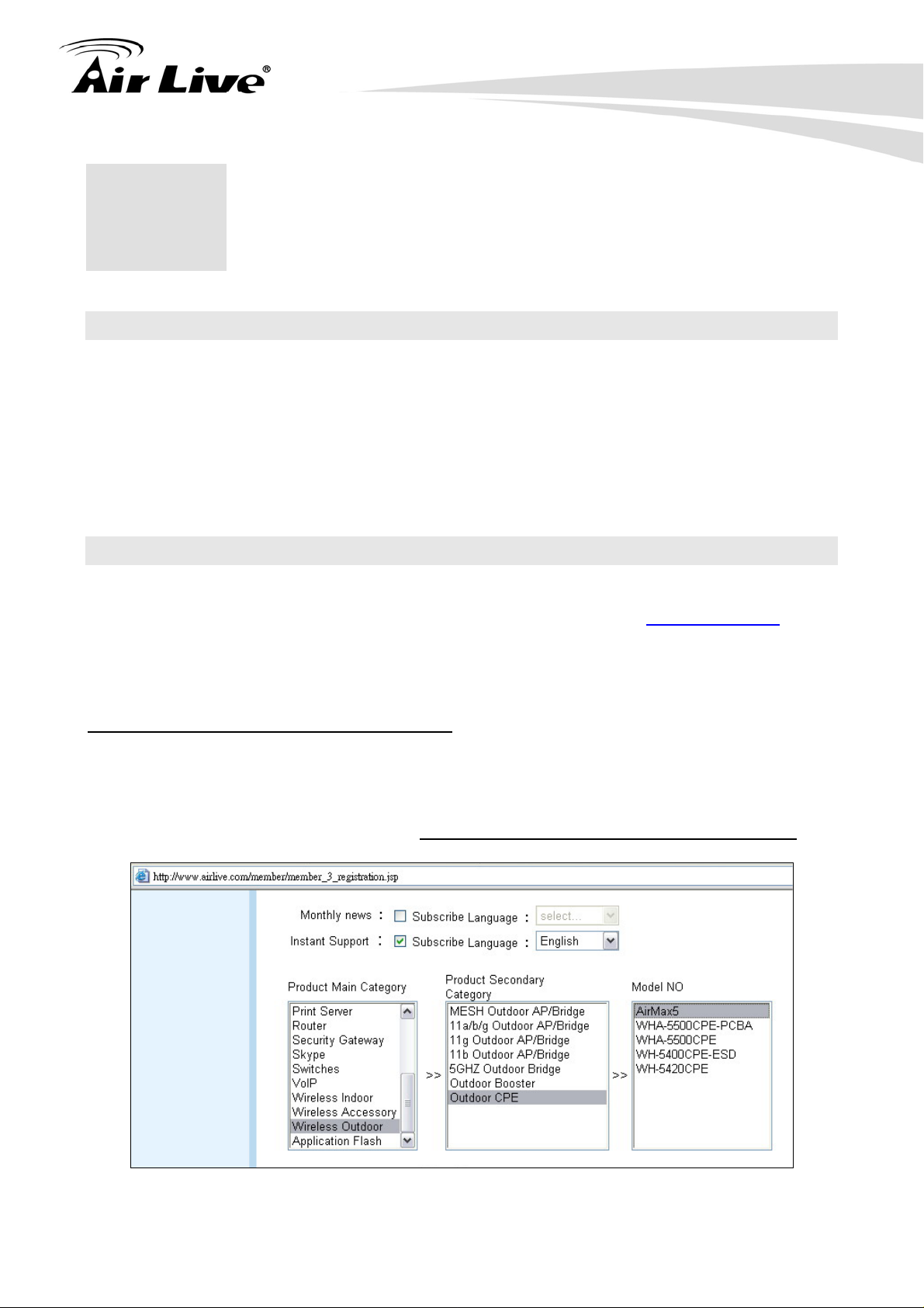
Since 2009, AirLive has added the “Newsletter Instant Support System” on our website.
AirLive Newsletter subscribers receives instant email notifications when there are new
download or tech support FAQ updates for their subscribed airlive models. To become an
AirLive newsletter member, please visit:
http://www.airlive.com/member/member_3.jsp
Figure: AirLive Newsletter Support System
1 AirLive IAR-5000 User’s Manual
Page 7

1. Introduction
1.3 Features
Sniffer and Bridge mode
SMTP, POP3/IMAP, HTTP, IM, Web SMTP, Web POP3, FTP, and Telnet Content
Record
IM, P2P, Web mail signature pattern update
IM Management
Application Management for Peer-to-Peer Sharing, Multimedia Streaming, Online
Gaming, VPN Tunneling, and Remote Controlling program
User Authentication
Content Auditing
Anomaly Flow IP
Remote Backup
AirLive IAR-5000 User’s Manual
2
Page 8
2. Install the IAR-5000
2. Installing the IAR-5000
2
This section describes the hardware features and the hardware installation procedure for
the IAR-5000. For software configuration, please go to chapter 3 for more details.
2.1 Before You Start
It is important to read through this section before you install the IAR-5000
The IAR-5000 is built-in with hard disk installed, so please install IAR-5000 gently
and carefully.
The default hard disk type and size is IDE 160 GB, you can change higher
capacity of hard disk to replace the original one.
You must power off IAR-5000 before to change hard disk. When new hard disk is
installed and power on IAR-5000, system will format hard disk automatically.
The maximum capacity of IDE hard disk is 750 GB.
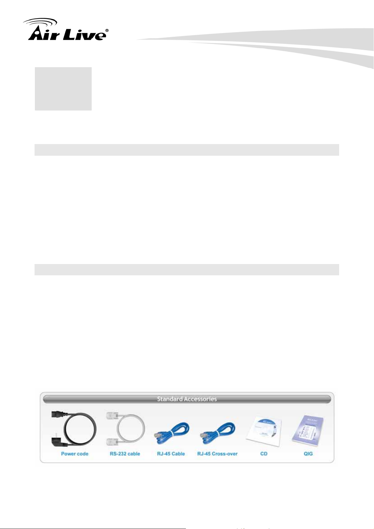
2.2 Package Content
The IAR-5000 package contains the following items:
One IAR-5000 main unit
User’s Guide CD
Quick Start Guide
CAT-5 UTP Fast Ethernet cable
CAT-5 UTP Fast Ethernet cross-over cable
RS-232 cable
Power code
Rack mount kits and accessories
3 AirLive IAR-5000 User’s Manual
Page 9
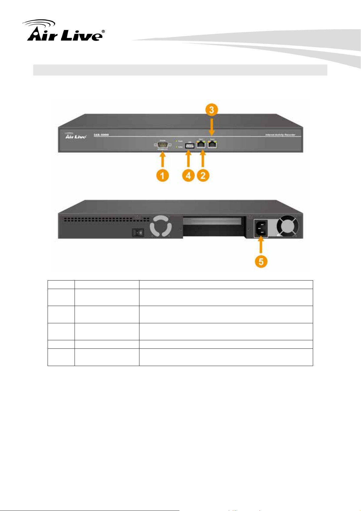
2.3 Knowing your IAR-5000
Below are descriptions and diagrams of the product:
2. Install the IAR-5000
No Port Description
1 Console Port
2 Port 1
3 Port 2
4 USB
5 AC Power
9-pin serial port connector for checking setting and
restore to the factory setting
Use this port to connect to a router, DSL router, or
Cable modem router
Use this port to connect to hub, switch, or switch’s
mirror port
Not Available
Input voltages ranging from 100 ~ 240 VAC, and with
a maximum power output of 85 watts.
AirLive IAR-5000 User’s Manual
4
Page 10
2.4 LED Table
IAR-5000:
No LED Color Status Description
1 POWER
2 Hard Disk
3
4
IAR-5000 v2:
No LED Color Status Description
1 POWER
2 Hard Disk
3
4
Port1 (L)
Port1 (R)
Port2 (L)
Port2 (R)
Port1 (L)
Port1 (R)
Port2 (L)
Port2 (R)
2. Install the IAR-5000
Green On Power on the device
Green Blinking Data reading / accessing
Orange Blinking Sending / Receiving
Green On 100 Mbps
Orange Blinking Sending / Receiving
Green On 100 Mbps
Green On Power on the device
Green Blinking Data reading / accessing
Orange Blinking Sending / Receiving
-- Off 10 Mbps
Green On 100 Mbps
Orange On 1000 Mbps
Orange Blinking Sending / Receiving
-- Off 10 Mbps
Green On 100 Mbps
Orange On 1000 Mbps
5 AirLive IAR-5000 User’s Manual
Page 11
2. Install the IAR-5000
2.5 Hardware Installation
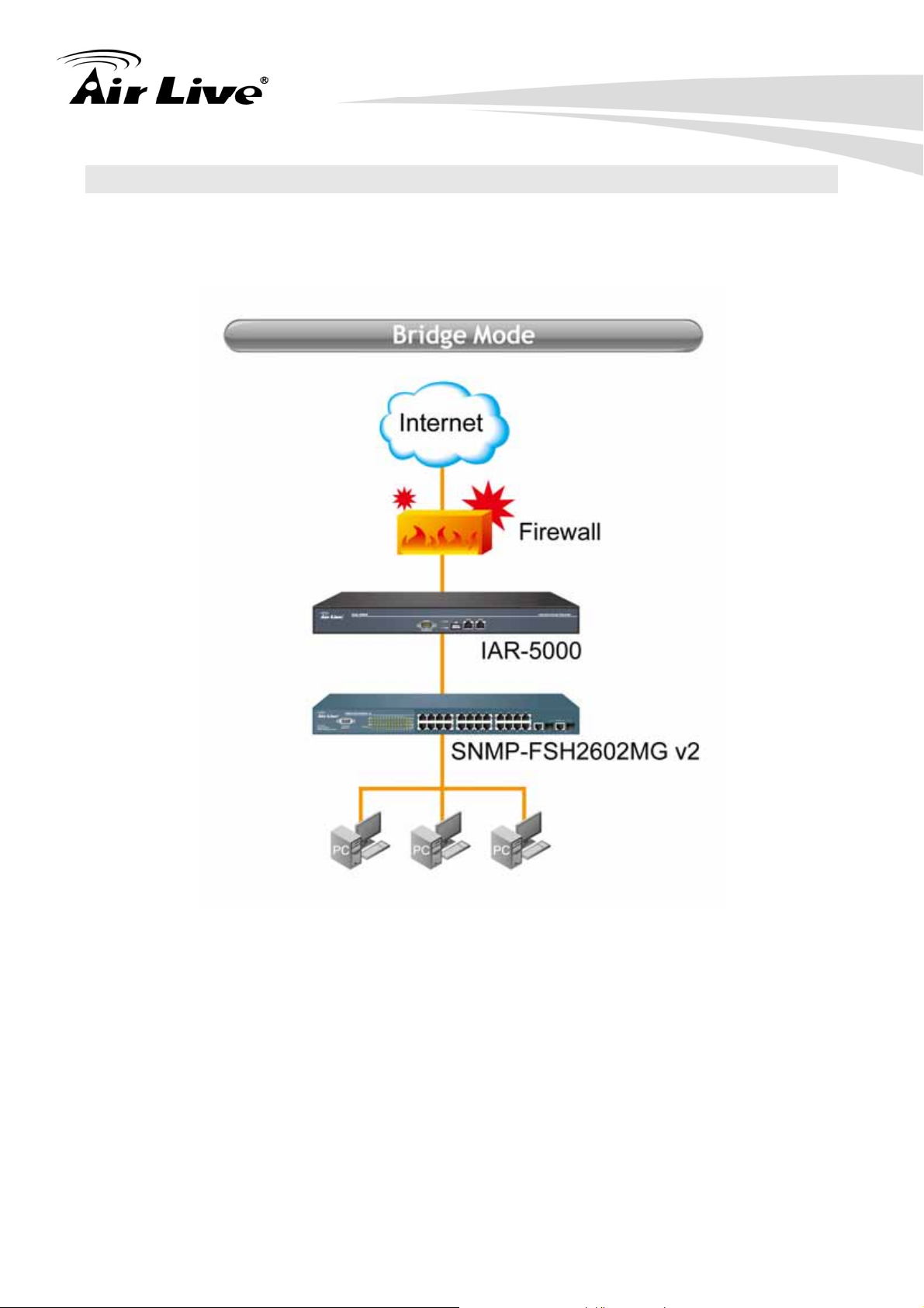
Bridge Mode: Connect the Port 1 to the firewall or gateway and Port 2 to a LAN
hub or switch.
AirLive IAR-5000 User’s Manual
6
Page 12

2. Install the IAR-5000
Sniffer Mode: Connect the Port 1 to the mirror port of a core switch or any port
available on a LAN hub and Port 2 to the network adaptor of the management PC.
Sniffer Mode Bridge Mode
Deployment
Anomaly Flow IP
Application Management
IM Management
Authentication
Connect Port1 to hub or
switch’s mirror port
Alert only Alert and Block connection
N/A Yes
N/A Yes
N/A Yes
Between LAN and firewall
Router
7 AirLive IAR-5000 User’s Manual
Page 13
2. Install the IAR-5000
2.6 Restore Settings to Default
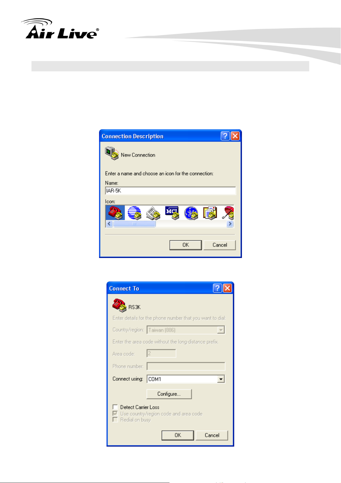
If you have forgotten your IAR-5000s IP address, you can restore your IAR-5000 to the
default settings by console. Please see diagram below for details.
1. Connect 9-pin RS-232 cable to PC and IAR-5000 console port.
2. Open Hyper Terminal program and configure the following settings.
3. Specify a name to the program
4. Select COM1 as the connecting type
AirLive IAR-5000 User’s Manual
8
Page 14
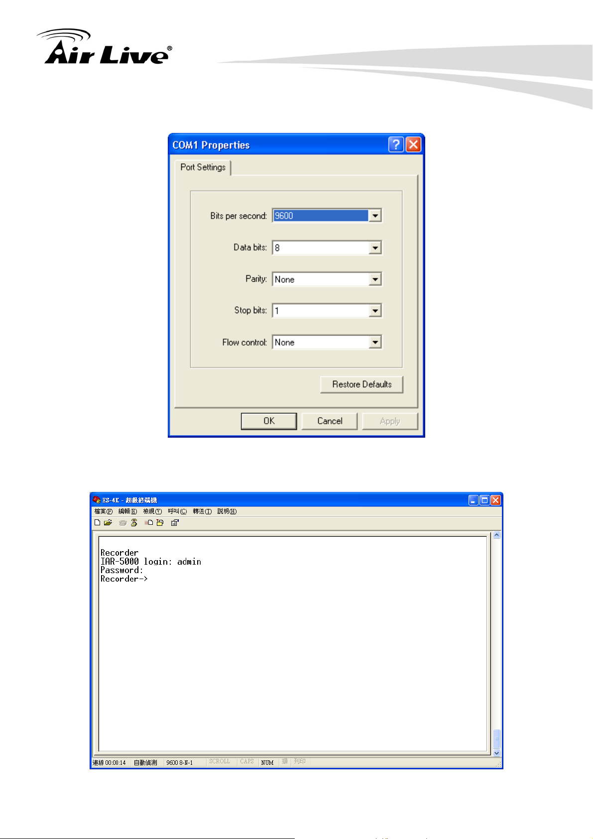
5. Fill in Port Setting as following value and clic k OK to save the setting
2. Install the IAR-5000
6. Press “Enter” and input Login name “admin” and password “airlive”.
9 AirLive IAR-5000 User’s Manual
Page 15
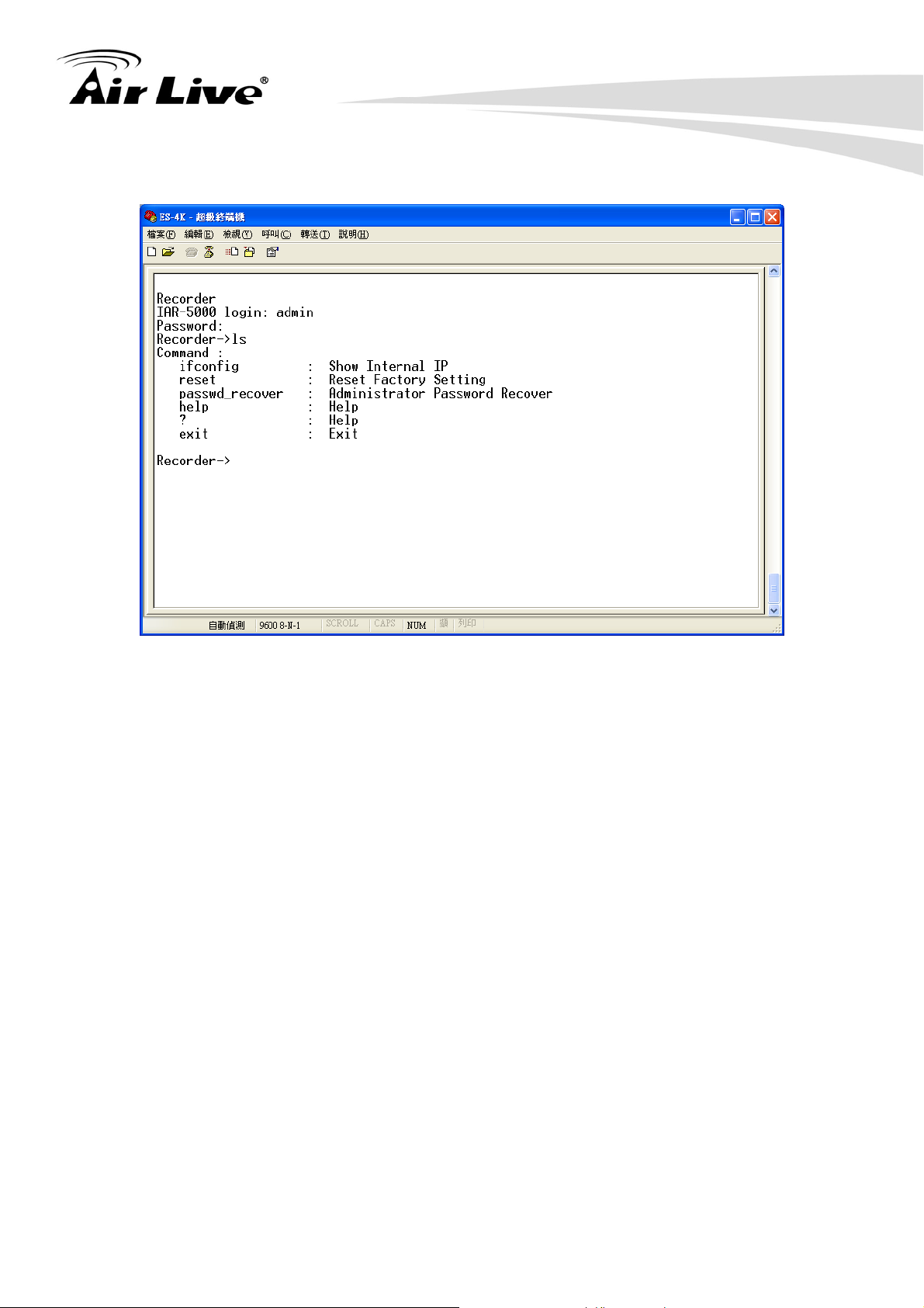
7. Type “ls” to display the command list
2. Install the IAR-5000
8. Type “reset” to reset the device as default.
AirLive IAR-5000 User’s Manual
10
Page 16

3. Configuring the IAR-5000
3. Configuring the
3
You can configure through standard web browser (http), secured web (https) management.
In this chapter, we will explain IAR-5000’s available management interfaces and how to get
into them. Then, we will provide the introduction on Web Management and recommended
initial settings.
IAR-5000
3.1 Important Information
The following information will help you to get start quickly. However, we recommend you
to read through the entire manual before you start. Please note the password is case
sensitive.
The default IP address is: 192.168.1.1 Subnet Mask: 255.255.255.0
The default user name: admin
The default password: airlive
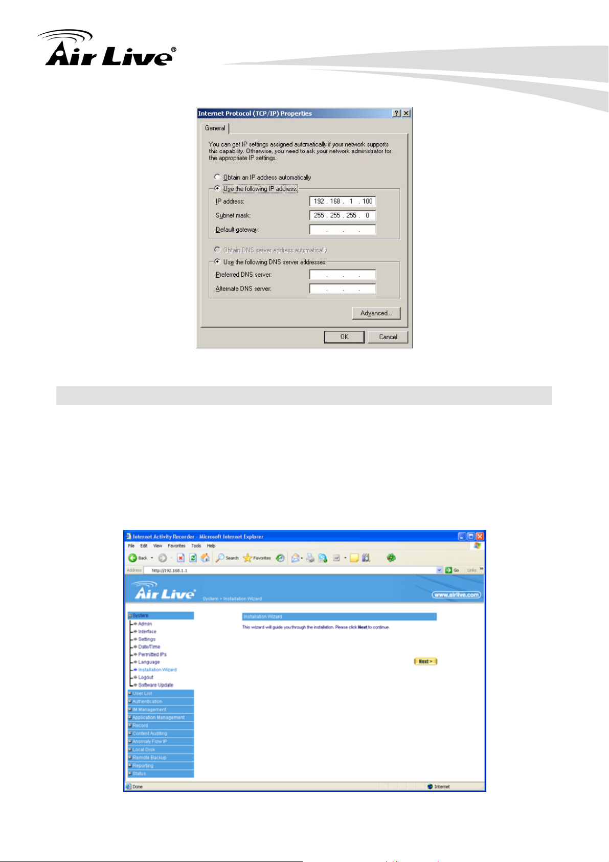
3.2 Prepare your PC
The IAR-5000 can be managed by a PC. The default IP address of the IAR-5000 is
192.168.1.1 with a subnet mask of 255.255.255.0. This means the IP address of the PC
should be in the range of 192.168.1.2 to 192.168.1.254.
To prepare your PC for management with the IAR-5000, please do the following:
1. Connect your PC directly to the Port1 on the of IAR-5000
2. Set your PC’s IP address manually to 192.168.1.100 (or other address in the same
subnet)
11 AirLive IAR-5000 User’s Manual
Page 17
3. Configuring the IAR-5000
You are ready now to configure the IAR-5000 using your PC.
3.3 Management Interface
The IAR-5000 can be configured using one the management interfaces below:
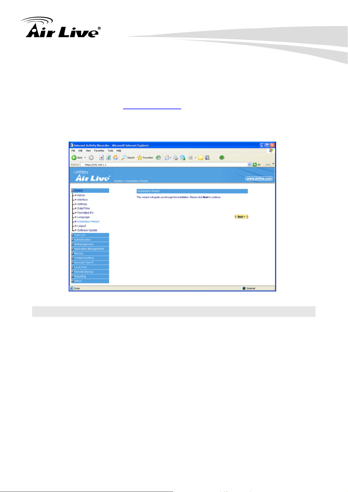
Web Management (HTTP): You can manage your IAR-5000 by simply typing its IP
address in the web browser. Most functions of IAR-5000 can be accessed by web
management interface. We recommend using this interface for initial configurations.
To begin, simply enter IAR-5000’s IP address (default is 192.168.1.1) on the web
browser. The default password is “airlive”.
AirLive IAR-5000 User’s Manual
12
Page 18
3. Configuring the IAR-5000
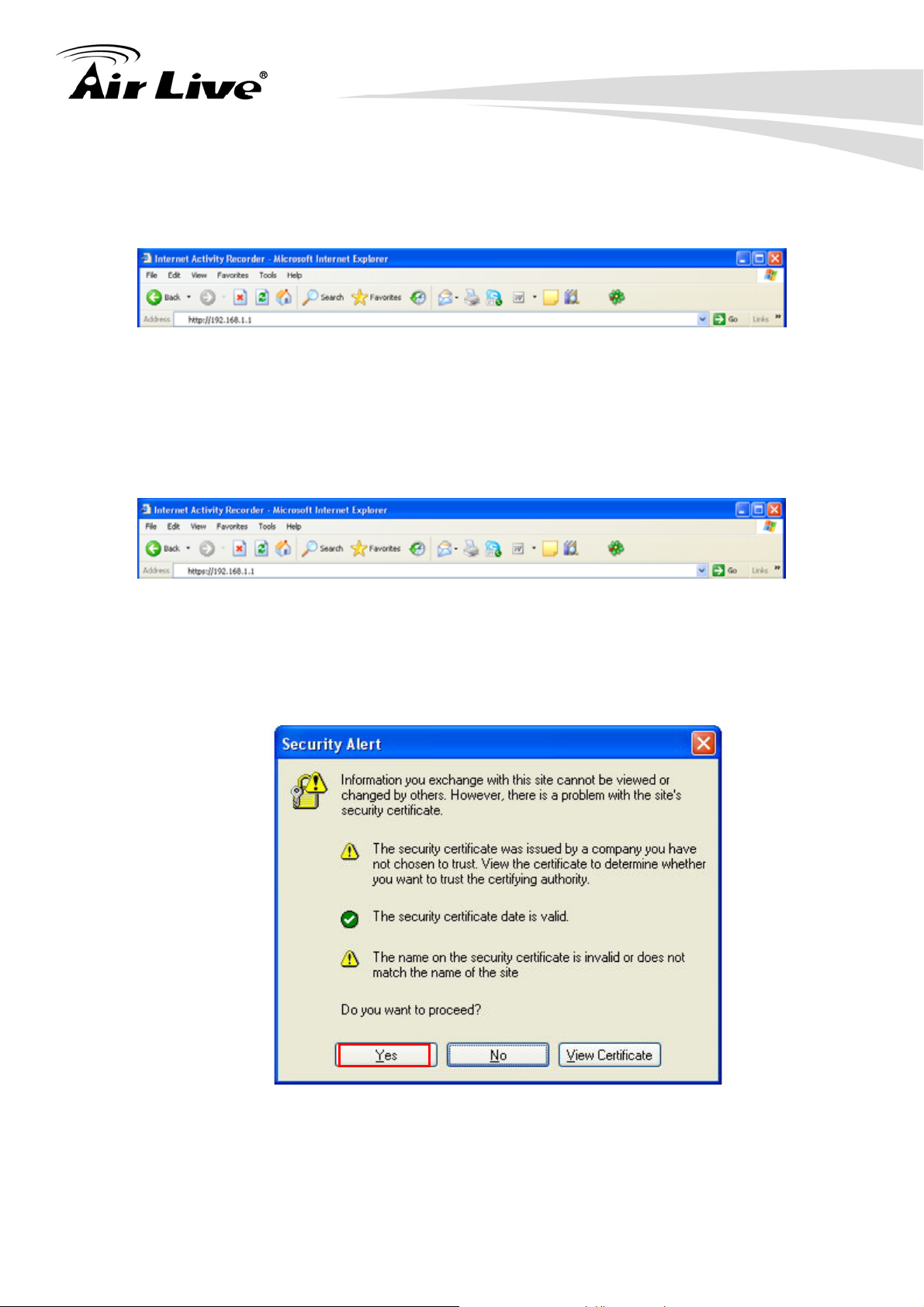
Secured Web Management (HTTPS): HTTPS is also using web browser for
configuration. But all the data transactions are securely encrypted using SSL
encryption. Therefore, it is a safe and easy way to manage your IAR-5000. We
highly recommend the Internet service provider to use HTTPS for management.
To begin, simply enter https://192.168.1.1 on your web browser. A security alert
screen from your browser will pop up. Please grant all permission and get certificate
to IAR-5000. After you pass the security warning screen, you will enter the
IAR-5000’s secured web management interface. The default password is “airlive”.
3.4 Introduction to Web Management
The IAR-5000 offers both normal (http) and secured (https) Web Management interfaces.
Their share the same interface and functions, and they can both be accessed through web
browsers. The only difference is HTTPS are encrypted for extra security. Therefore, we
will discuss them together as “Web Management” on this guide.
If you are placing the IAR-5000 behind router or firewall, you might need to open virtual
server ports to IAR-5000 on your firewall/router
HTTP: TCP Port 80
HTTPS: TCP/UDP Port 443
This procedure is not necessary in most cases unless there is a router/firewall between
your PC and IAR-5000.
13 AirLive IAR-5000 User’s Manual
Page 19
3. Configuring the IAR-5000
Normal Web Management (HTTP)
To get into the Normal Web Management, simply type in the IAR-5000’s IP address (default
IP is 192.168.1.1) into the web browser’s address field.
Secured Web Management (HTTPS)
To get into the Secured Web Management, just type “https://192.168.1.1” into the web
browser’s address field. The “192.168.1.1” is IAR-5000’s default IP address. If the IP
address is changed, the address entered in the browser should change also.
A security warning screen from your browser will then pop-up depending on the browser
you use. Please follow step below to clear the security screen.
Internet Explorer: Select “Yes” to proceed
AirLive IAR-5000 User’s Manual
14
Page 20
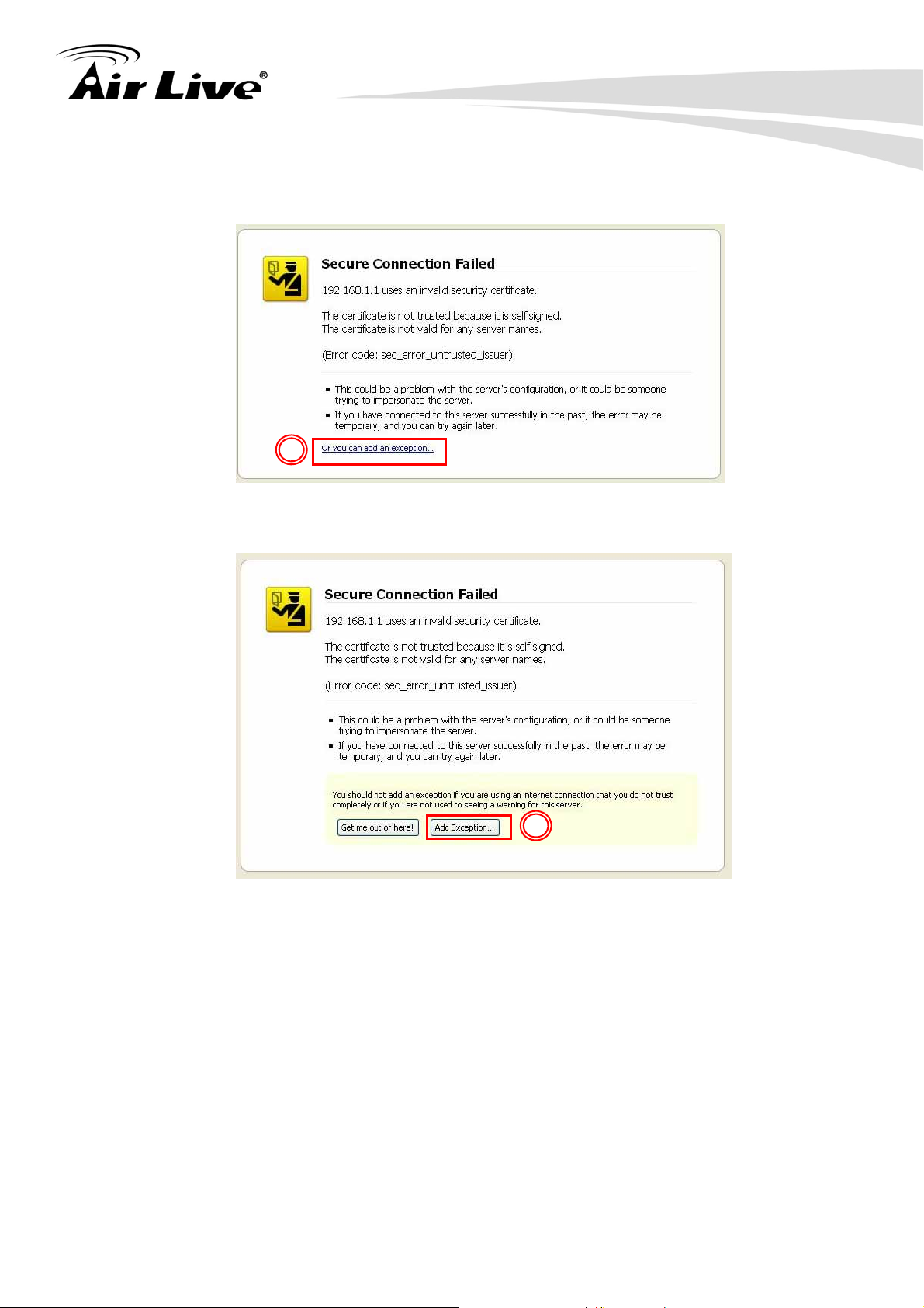
Firefox:
1. Select “or you can add an exception”
3. Configuring the IAR-5000
1
2. Click on “Add Exception”
2
3. Click on “Get Certificate”. Then, please enter IAR-5000’s IP address. Finally,
please click on “Confirm Security Exception.”
15 AirLive IAR-5000 User’s Manual
Page 21

3. Configuring the IAR-5000
3
4
3.5 Initial Configurations
We recommend users to browse through IAR-5000’s web management interface to get an
overall picture of the functions and interface. Below are the recommended initial
configurations for first time login:
Step1. Connecting the administrator’s PC and IAR-5000 (port1 or port2) to the same hub
or switch, and then use the web browser ” IE or Netscape” to connect IAR-5000.
The default IP port address in IAR-5000’s management interface is
http://192.168.1.1.
Step2. The browser prompts you for the user name and password.
User Name: admin
Password: airlive
Click on OK
AirLive IAR-5000 User’s Manual
16
Page 22
3. Configuring the IAR-5000
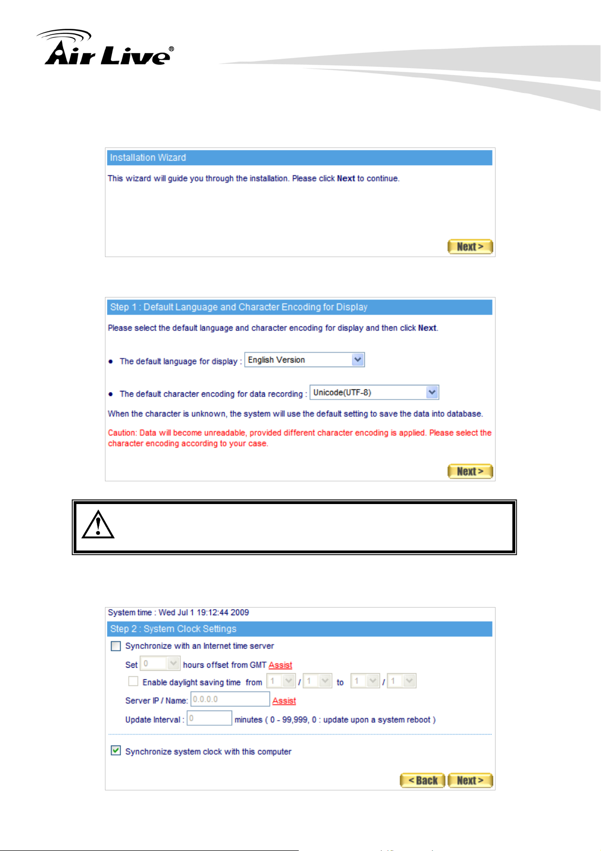
Step3. You will be brought to the Installation Wizard screen during your first login. It will
guide you through the settings.
Step4. Select the language and character encoding for your management interface.
Default character encoding will be used on emails with unspecified
character encoding
Step5. Tick Synchronize with an Internet time server as well as configure the offset
hours from GMT to ensure the time correctness.
17 AirLive IAR-5000 User’s Manual
Page 23
3. Configuring the IAR-5000
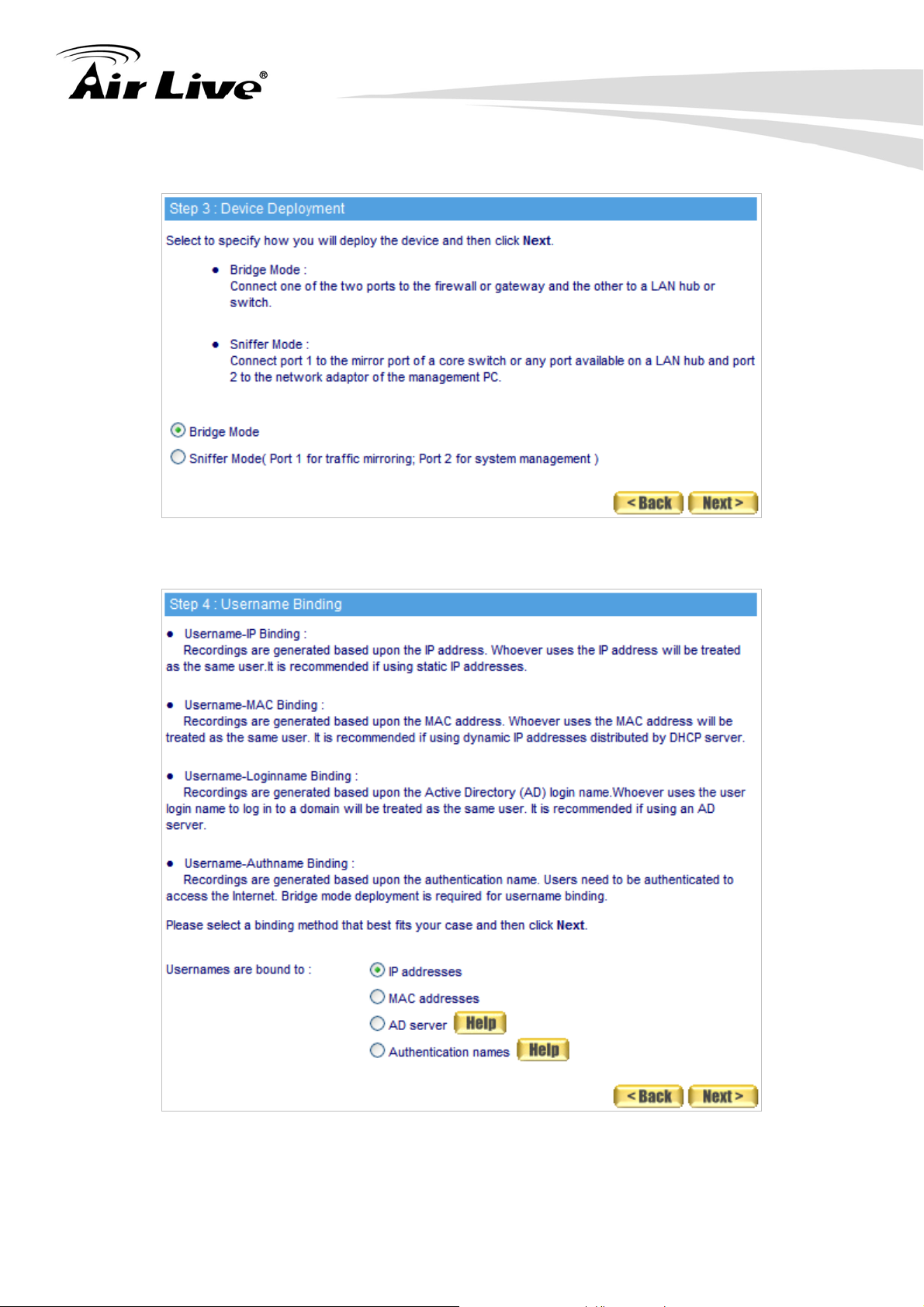
Step6. Select an operating mode based on how the device is deployed.
Step7. Choose the basis for recording users’ online activities.
AirLive IAR-5000 User’s Manual
18
Page 24
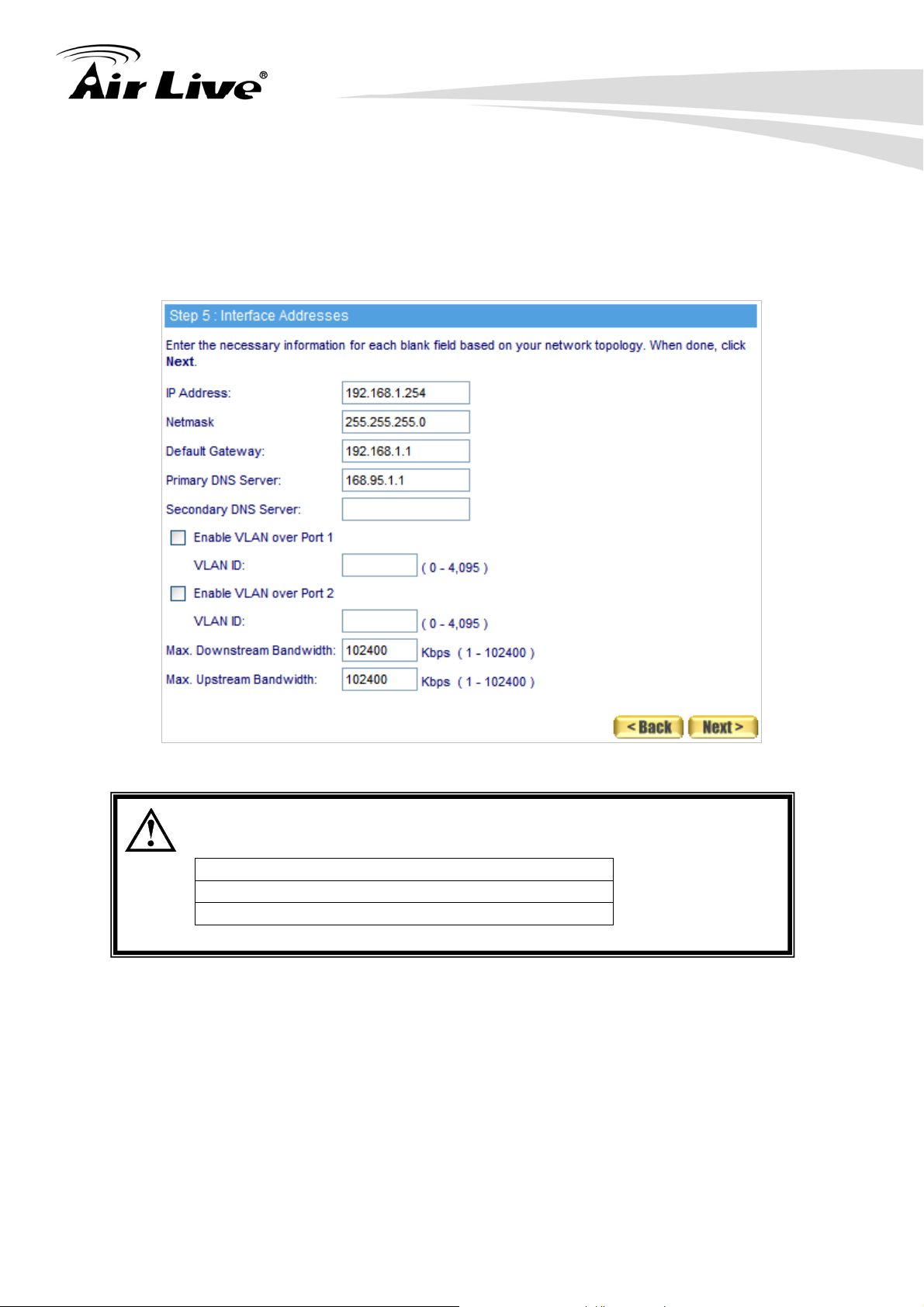
Step8. Configure the related interface addresses.
Type a valid IP address from the LAN subnet in the IP Address field and
configure its netmask, default gateway and DNS address accordingly.
To use VLAN, tick Enable VLAN over Port 1 or 2 based on your case and
also assign a VLAN ID to the port.
Specify the maximum downstream and upstream bandwidth respectively.
3. Configuring the IAR-5000
For your reference, you may configure your management address
based on the subnet ranges below:
10.0.0.0 - 10.255.255.255
172.16.0.0 - 172.31.255.255
192.168.0.0 - 192.168.255.255
19 AirLive IAR-5000 User’s Manual
Page 25
3. Configuring the IAR-5000
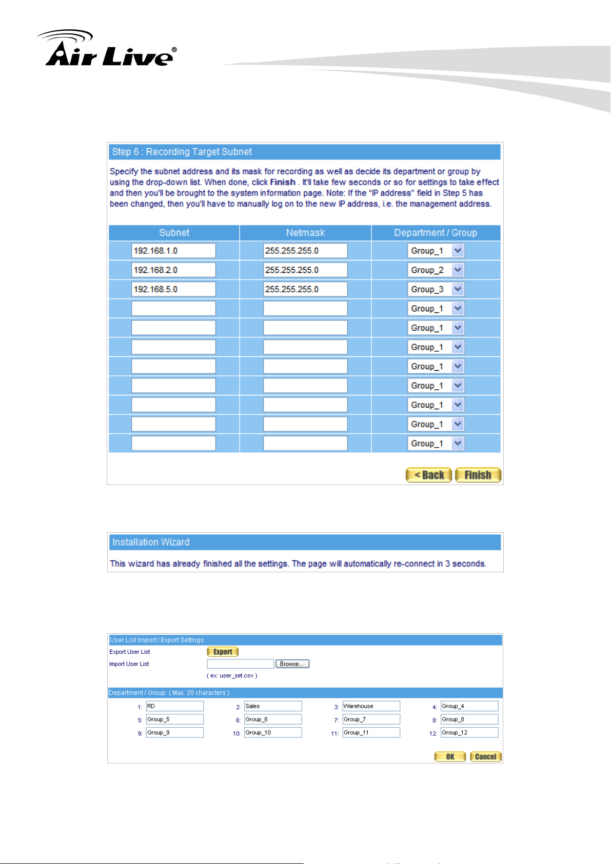
Step9. Configure the device to record the online activities of specific departments or
groups by specifying its subnet and mask address.
Step10. Click on Finish.
Step11. Navigate to User List Æ Settings, and then give each department or group a
friendly name.
AirLive IAR-5000 User’s Manual
20
Page 26

3. Configuring the IAR-5000
Step12. Under User List Æ Logged, users within the same subnet as the management
address will be included in the same subnet category. In another word, IAR-5000
classifies users by the identity of subnet. Also, the device allows system
administrator to customize user lists for users resided in other subnets.
3.6 About IAR-5000’s Menu Structure
The device’s user interface consists of the following two areas:
The left panel contains all the selectable menu items.
The configuration panel on the right provides all the available settings for
any selected menu item.
Click on OK
Main Menu Configuration
21 AirLive IAR-5000 User’s Manual
Page 27
4. System
4. System
4
The so-called system administration refers the competency to manage the IAR-5000. In
this Chapter it will be defined to the Admin, Interface IP, Setting, Date/Time, Permitted IPs,
Language, Logout and Software Update.
The IAR-5000 is managed by the main system administrator. The main system
administrator can add or delete any system settings and monitor the system status. The
other group administrator have no competency to modify the system settings (the
administrator’s name is set by the system main administrator), only can monitor the system
status.
4.1 Admin
Administrator/ Group administrator:
The name of system administrator and group administrator . Administrator is the default
name of system administrator in IAR-5000, and it can not be canceled; otherwise the
group administrator can change or cancel it.
The default system administrator can add or modify the other administrator, and also
can decide if the group administrator has the competency to write into main system.
On the other hand, the group administrator who has the write privilege can modify the
competency of default system administrator, or only has the competency to read.
There must be at least one administrator who has the competency to read and write in
IAR-5000.
The default of system administrator in IAR-5000: Account /
password: admin / airlive.
Privilege:
The administrator, who has the competency to read/write, can change the system
settings, monitor the system status, to add and cancel other administrators.
The administrator, who has the competency to read, only can monitor the system
status, but has no competency to change any settings.
Password/New Password/Confirm Password:
To add or modify the main group administrator password.
AirLive IAR-5000 User’s Manual
22
Page 28
4. System
Group Monitoring:
The group administrator can divide the internal network into several groups. And he
can appoint the specific administrator to view the group but can not view across
groups.
Add New Group-Admin:
Step1. In admin setting window, click the New-Group Admin.
Step2. In add new group-admin window, enter the following information. (Figure 4-1)
Group-Admin set group_admin.
Password enters 12345.
Confirm Password enters 12345.
In View Groups column, select the permitted group record to see.
Step3. Click OK to login the user or click cancel, to delete the new group administrator .
Figure 4-1 Add new group-admin
Change Admin password:
Step1. Find the administrator’s name that correspond to the right column, then click
modify.
Step2. Modify admin password or modify group admin password window. And then
enter the following information:
Password enters airlive.
New Password enters 52364.
Confirm Password enters 52364. (Figure 4-2)
Step3. Click OK to modify the password or click cancel to cancel the setting.
23 AirLive IAR-5000 User’s Manual
Page 29
4. System
Figure 4-2 To change the admin password
4.2 Interface
Interface Address:
The administrator can set the IP login information in IAR-5000.
Ping:
Enable the function, the user can send Ping (ICMP) packets to Interface.
HTTP:
Enable this function, the user can login IAR-5000 Web UI through HTTP protocol.
HTTPS:
Enable this function, the user can login IAR-5000 Web UI through HTTPS protocol.
Download Bandwidth and Upstream Bandwidth:
The system administrator should set the accurate bandwidth of WAN, in order to be the
basic operation of IAR-5000.
Step1. In System Æ Interface, enter the following setting:
Enter the available IP of the LAN subnet in IP Address, Netmask and
Default Gateway column.
Enter DNS server 1 or DNS server 2.
If necessary, select to enable VLAN feature and provide the VLAN ID
based on the setting.
Enter Max Downstream Bandwidth and Max Upstream Bandwidth.
(It depends on the applied flow statistics of the user.)
Enable the setting of Ping, HTTP and HTTPS function.
Click OK. (Figure 4-3)
AirLive IAR-5000 User’s Manual
24
Page 30
4. System
Figure 4-3 The interface IP setting
Please do not cancel HTTP and HTTPS before setting the Interface,
because it will let the system administrator could not enter the WebUI
of IAR-5000.
4.3 Settings
System Settings:
The system administrator can import or export the system settings, or they can also
reset the factory setting and format the disk.
Database Check / Repair:
The records can be inspected and / or fixed if damaged or displayed improperly. To
obtain the best performance, please execute it when the network traffic is low in order
to avoid system overload.
System E-mail Notification:
To activate this option, the system administrator will receive the caution message
automatically when IAR-5000 is in the unpredictable trouble.
Device Deployment:
Bridge mode operates as: Port 1 and port 2 function individually.
25 AirLive IAR-5000 User’s Manual
Page 31

4. System
Sniffer mode operates as: Port 1 serves as a packet receiver connected to the mirror
port of a core switch whereas port 2 connected to any other port available on that core
switch acting as a management use for system administrator.
Management over Web Browser:
Management port enables the device to be remotely accessed from anywhere via a
Web browser. The port number for whether HTTP or HTTPS protocol is alterable.
If a wrong password has been entered and it exceeds the maximum allowed attempts,
the users IP address can be blocked to prevent unauthorized modification.
Log Storage Time
System administrator can set the log storage time.
When the port number of HTTP and HTTPS had been changed, if the
system administrator wants to log in to WebUI, he must change the
WebUI port number. (For example:
http://172.16.3.254:8080 and
https:// 172.16.3.254:1025)
Export the configured file:
Step1. In System Æ Setting Æ System Settings, select Export System settings,
and click the Export button at the right place.
Step2. When it appeared File Download window, click Save button, and it will show
where the file will be saved, then click Save button again. The settings of
IAR-5000 will be copied to the appointed directory. (Figure 4-4)
Figure 4-4 Choose where the export file will be saved
AirLive IAR-5000 User’s Manual
26
Page 32

4. System
Import the configured file
Step1. In System Æ Setting Æ System Settings, select Import System Settings,
then click Browse button at right place.
Step2. In Choose File window, choose the directory of former saved file in IAR-5000,
and choose the correct setting, then click Open. (Figure 4-5)
Step3. Click the lower right OK, the window will closed.
Step4. Click the OK inside the confirm dialogue box, the setting will import to IAR-5000.
(Figure 4-6)
Figure 4-5 Import the file name to the directory to saved
Figure 4-6 Confirm the import setting
27 AirLive IAR-5000 User’s Manual
Page 33

4. System
Reset Factory Default
Step1. In System Æ Settings Æ System Settings, select Reset Factory Setting and
Format Hard Disk.
Step2. Click the OK in the lower right, it will restore to the factory setting of IAR-5000
and format the disk at the same time. (Figure 4-7)
Figure 4-7 Select Reset Factory Setting
Configure System Email Notification
Step1. Select Enable email notification under System Email Notification section.
Step2. Company Name, enter the name of the company which belong the IAR-5000.
Step3. Device Name, enter the name of IAR-5000.
Step4. Sender Address, sending the e-mail address of the sender.(Some of the ISP
have request to enter in the sender address column)
Step5. SMTP Server, enter the IP address of the delivered e-mail in SMTP server.
Step6. Notification Address 1, enter the e-mail address in the first one position to
receive the alarm message.
Step7. Notification Address 2, enter the e-mail address in the second position to
receive the alarm message.
Step8. Click the lower right OK to set the function of message alarm. (Figure 4-8)
AirLive IAR-5000 User’s Manual
28
Page 34

4. System
Figure 4-8 Enable the instant mail message alarm of IAR-5000
Select Enable SMTP authentication and enter the username and
password, then click Mail Test button to test Notification Address 1
and Notification Address 2, to see if the e-mail sending address can
receive the current caution message.
Device Reboot
Step1. Click on the Reboot button next to Reboot System.
Step2. A confirmation conversation box appears saying, ”Are you sure to reboot ?“
Step3. Click OK to reboot IAR-5000, or click Cancel to cancel reboot IAR-5000.
(Figure 4-9)
Figure 4-9 Reboot the internet recorder appliance
29 AirLive IAR-5000 User’s Manual
Page 35

4. System
4.4 Date/Time
System Clock Settings
The date and time settings can be configured by either syncing to an Internet time
server or syncing to the computer’s clock.
GMT
The short form for Greenwich Mean Time. It is the international standard time.
Daylight Saving Time
Daylight saving time (DST; also summer time) is the portion of a year in which a
region's local time is advanced by an hour from its standard official time.
Step1. Select Enable Synchronize with an Internet Time Server. (Figure 4-10)
Step2. Click Set Offset Hours from GMT pull down menu, and choose the correct
time.
Step3. Enter the Server IP address into Server IP / Name.
Step4. Enter the frequency of the updating time in Update interval minute.
Figure 4-10 System time setting
Select Synchronize Æ Sync button, the system time in IAR-5000, will
synchronize to the administrator’s computer.
The settings of Set offset hours from GMT and Server IP can be
entered with using Assist.
AirLive IAR-5000 User’s Manual
30
Page 36

4. System
If the local area executes the daylight saving time, then enable the
daylight saving time setting.
4.5 Permitted IPs
Creating a Permitted IP Address
Step1. In System Æ Permitted IPS Æ New Entry, add the new setting: (Figure 4-11)
Name enters master.
IP Address enters 172.16.0.2.
Netmask enters 255.255.255.255.
Service selects Ping, HTTP and HTTPS.
Click OK.
Complete Permitted IPs settings. (Figure 4-12)
Figure 4-11 The Permitted IPs setting
Figure 4-12 Complete the Permitted IPs setting
If you want the Permitted IPs to be real working, when it must be
connected from the administrator to the interface of IAR-5000 WebUI,
but the settings of Ping, HTTP and HTTPS all must be canceled.
Before you cancel the interface address of HTTP and HTTPS, you
have to set the Permitted IPs first or it will not connect to WebUI
through the internet.
31 AirLive IAR-5000 User’s Manual
Page 37

4. System
4.6 Logout
Logging out the Management Interface
Step1. Click the Logout icon in the up right of Web UI, it can let the system
administrator to log out from the system admin anytime, and also prevent other
person change the settings of IAR-5000. (Figure 4-13)
Figure 4-13 Confirm to logout
Step2. Click OK, it shows the logout information. (Figure 4-14)
Figure 4-14 The logout WebUI
4.7 Software Update
Updating Firmware
Step1. In System Æ Software Update, the user can update the firmware step by step:
In Version Number, we can know the current version of the software. Go on
the internet to gain the newest version of the firmware and download into
the storage disk in IAR-5000.
Click Browse Æ Choose file, select the newest version of the software.
Click the lower right OK, it will process the update. (Figure 4-15)
AirLive IAR-5000 User’s Manual
32
Page 38

4. System
Figure 4-15 Software update
It needs 3 minutes to update the software, and will reboot after
updated the system. Please do not turn it off, off line and exit the web
page during the update, or it will cause the error in IAR-5000. (It is
recommended using the LAN to update.)
33 AirLive IAR-5000 User’s Manual
Page 39

5. User List
5. User List
5
This chapter is about the users can be monitored by the IAR-5000. It can automatic search
and add the new users, and the system administrator can add the lists by himself.
User List Configuration:
Administrator can export the monitor user list and some related settings to the PC or
import these settings into IAR-500.
Department / Group :
The administrator can group the users according to the network structure, so that he
can manage the system more easily.
The company can be divided into several departments, and part of the user
(department) settled in different subnet.
Step1. In User List Æ Setting, set the following settings:
To set the Department / Group depends on the real network deployment.
Click OK (Figure 5-1)
Figure 5-1 Set the user list
Step2. In User List Æ Logged, add the new user.
Click of 172.16.0.0 subnet and the IAR-5000 will search the new user in
the subnet. (Figure 5-2)
Wait 1~2 minutes until search complete. (Figure 5-3)
If system administrator wants to search users in specific subnet, set the
search IP range and click search.
Select the new user to add, click New User. (Figure 5-4, 5-5)
AirLive IAR-5000 User’s Manual
34
Page 40

5. User List
Figure 5-2 Click search new user button
Figure 5-3 Starting to search new user
Figure 5-4 Select the new user to add
35 AirLive IAR-5000 User’s Manual
Page 41

5. User List
Figure 5-5 Complete to add the new user
The subnet in which management address resided is set to be the first
subnet on user list. Users from that subnet will be shown under User
List Æ Logged.
A user will be automatically added on Logged list once the device
detects his / her accessing the Internet.
Given that the Primary DNS Server (or secondary) is using an
internal DNS server, then the device would request that DNS server
for users’ DNS names while performing user searching.
User names may be displayed in various forms. The display name of
a user / client will be chosen from its computer name, its entry from
the DNS server, then its IP / MAC address. (If computer name and
DNS name are not available, then IP or MAC address will be used.
Whether IP or MAC address will be used is determined by the User
names are bound to IP / MAC addresses setting under Record Æ
Settings Æ Settings.)
AirLive IAR-5000 User’s Manual
36
Page 42

Step3. Modify the user in user list:
Click User Name of JACKY
User Name, enter Jacky_PC.
Department / Group, select Laboratory.
Click OK. (Figure 5-6, 5-7, 5-8)
Click User Name of OCT1005.
User Name, enter Gateway.
Department / Group, select Device_Room.
Select move this user to ignored user list.
Click OK, then the user will be removed to ignore user list. (Figure 5-9, 5-10,
5-11)
Repeat the steps to complete modifying the user list. (Figure 5-12)
5. User List
Figure 5-6 Select the user to modify
Figure 5-7 Enter the user information to modify
Figure 5-8 Complete to modify the user information
37 AirLive IAR-5000 User’s Manual
Page 43

5. User List
Figure 5-9 Select the user to modify
Figure 5-10 Enter the user information to modify
Figure 5 -11 Move the user to ignored user list
AirLive IAR-5000 User’s Manual
38
Page 44

Figure 5-12 Complete to modify the user list
In Ignored user list, the system administrator can also select the
user to move to logged user list.
Step4. In User List Æ Logged, add the new subnet:
Click Add.
Subnet, enter 192.168.139.1.
Netmask, enter 255.255.255.0.
Add a New user to this Department / Group, select RD.
Click OK. (Figure 5-13)
5. User List
Figure 5-13 Add a new subnet
The Department / Group that selected by system administrator,
which will become the default Department / Group in this subnet.
Step5. Repeat Step 2 to Step 4 until finish to set the user list.
39 AirLive IAR-5000 User’s Manual
Page 45

5. User List
Change the user list by import the user list configuration (excel list)
Step1. In User List Æ Setting Æ User List Configuration Æ Export User List to
Client PC Æ click .
Step2. When it appears File Download, click Save, choose the position to save the
download file, then click Save again. The user list settings will be saved in
IAR-5000. (Figure 5-14)
Figure 5-14 Select the position to save the download file
Step3. Under User List Æ Settings, import the edited user list onto IAR-5000.
Run Excel to edit the previously downloaded user list. (default file name:
user_set.csv) (Figure 5-15)
AirLive IAR-5000 User’s Manual
40
Page 46

5. User List
Figure 5-15 Editing the User List in Excel
Step4. Change the information of Department / Group.
Change the 8th Department / Group information, and the original
Customer_Service will change into Support.
Add the 12th Department /Group information, and change Group_12 into
R.D._2. (Figure 5-16)
41 AirLive IAR-5000 User’s Manual
Page 47

5. User List
Figure5 -16 Change the Department / Group information from excel
Step5. To add and modify the user information in the first subnet. (Figure 5-17)
Change 192.168.1.2(Jacky)Department / Group information, and change
the 1th Department / Group into 9th Department / Group.
Insert a row under the user list in the first subnet, and enter the new user
information in the row.(User IP , User Name, PC Name, Logged / Ignored
User List, User MAC, User Department / Group)
Figure 5-17 To add or modify the user’s first subnet information from the excel
In the Logged / Ignored user information, the ” 0” number represents
Ignored, the “ 3 “ number represents Logged.
The “ * “ symbol represents no information in the excel tablet.
AirLive IAR-5000 User’s Manual
42
Page 48

5. User List
Step6. Add the third subnet and user’s information. (Figure 5-18)
Please enter the third subnet basic information under the second subnet
user list .(the range of IP, Netmask, and Default Group).
Please enter the basic user information under the third subnet.(User IP, User
Name, PC Name, Logged / Ignored List, User MAC, User Department /
Group).
Figure 5-18 Add the user’s information in the third subnet by excel\
Leaving a blank row as a separator in between any two subnet
information is essential while editing user list in Excel.
Step7. Save File(user_set.csv)
Step8. In User List Æ Setting, Click User List Configuration Æ Import User List
from Client PC Æ Browse.
Step9. In the Choose File window , select the modified user list setting, then Click Open.
(Figure 5-19)
43 AirLive IAR-5000 User’s Manual
Page 49

5. User List
!
Figure 5-19 Selecting the Edited User List to Import
Step10. Click the lower right OK, the user list setting files will import into IAR-5000.
Modify the Information of the desirable user:
Step1. Click on the desirable user to change its user information. (Figure 5-20)
Step2. Type a proper user name.
Step3. Select the proper dept. / group. (Figure 5-21)
Step4. Modification is completed.
Figure 5-20 Selecting the Desirable User to Change User Information
AirLive IAR-5000 User’s Manual
44
Page 50

Figure 5-21 Modifying the User Information
System administrator can record or ignore the online activities of a
specific internal user simply by selecting the user on the user list and
then click on Logged or Ignored button on the top of the first list.
Add a new subnet:
Step1. Navigate to User List Æ Logged, and then add a new subnet.
Click on Add next to Subnet.
Subnet Address: T ype 192.168.139.0
Netmask: Type 255.255.255.0
Classify new users into: Select R.D. (customize accordingly)
(Figure 5-22)
Refer to Step 2 in page 34 to add users resided in the subnet. (Figure 5-23)
5. User List
Figure 5-22 Adding a Subnet to be Recorded
Figure 5-23 New User List Added
45 AirLive IAR-5000 User’s Manual
Page 51

6. Authentication
6. Authentication
6
The device supports four types of authentication: RADIUS, POP3, LDAP and the device’s
inbuilt user authentication. The IT administrator may regulate users’ Internet access using
these authentication mechanisms.
6.1 Settings
Authentication Settings:
Authentication Port: The port number used for authentication mechanism. It is “82”
by default.
Log users off if idle for: You can specify a period of time to log off idle users. If the
idle time of a user has exceeded the value specified, the authentication of the user will
automatically expire. Default value is “30”.
Disable multiple logins using the same authentication name: Users will fail to be
authenticated if using the same name.
Automatically direct the authentication user to the web page: Users will be taken
to the web page specified right after authentication. If leaving the field blank, users will
have direct access to their desirable web page.
The message to display on the authentication window: The informative or greeting
message (support HTML language) for authenticated users. To discard the setting and
leave the field blank.
Authentication-Free List: Users can be exempted from the authentication
mechanism by specifying their IP addresses on the list.
Procedure to pass Authentication:
Define the Authentication settings. (Figure 6-1)
AirLive IAR-5000 User’s Manual
Figure 6-1 General Authentication Settings
46
Page 52

6. Authentication
Surf any webpage, user will see: (Figure 6-2)
Figure 6-2 The Login Screen for Authentication Mechanism
The designated web site will show up after passing authentication. (Figure 6-3)
Figure 6-3 The Designated Web Site for Authentication Login
The device’s authentication mechanism requires Bridge mode
deployment.
The login screen for authentication is available by a manual input of
the device’s management address appended with the authentication
port number in the Address field of a web browser.
47 AirLive IAR-5000 User’s Manual
Page 53

6. Authentication
6.2 Auth User
Auth Name:
The authentication name for a user.
Password:
The password for the authentication.
Confirm New Password:
The confirmation of the password.
Regulate Users’ Internet Access:
Step1. Under Authentication Æ Auth User, create as many authenticated users as
needed. (Figure 6-4)
Figure 6-4 Creating Authenticated Users
Step2. The login screen for authentication will show upon users’s web browsing
attempt. If the login information is correctly applied, the authentication will be
successful. (Figure 6-5)
Figure 6-5 The Login Screen for Authentication Mechanism
AirLive IAR-5000 User’s Manual
48
Page 54

6. Authentication
Step3. To log out of the authenticated session, click on Logout in the Authentication
Logout window. If the window has been closed, please enter http://device’s
management address:authentication port/logout.html (ex. http://192.168.1.1:82)
in the Address field of a web browser to re-open the window.. (Figure 6-6)
Figure 6-6 The Window for Logging Out the Authenticated Session
6.3 RADIUS
RADIUS Server Secret
The password for the RADIUS authentication.
802.1x RADIUS Server Authentication
Provides your RADIUS authentication with Port-based Network Access Control
How to setup a Windows-based RADIUS server
Step1. Navigate to Start Æ Settings Æ Control Panel Æ Add/Remove Programs
and then click on Add/Remove Windows Components from the left panel.
Step2. Networking Services from the components and then click on Details.
(Figure 6-7)
Figure 6-7 Windows Components Wizard
49 AirLive IAR-5000 User’s Manual
Page 55

Step3. Select Internet Authentication Services. (Figure 6-8)
6. Authentication
Figure 6-8 Adding Internet Authentication Services from the Subcomponents
Step4. Navigate to Start Æ Control Panel Æ Administrative Tools and then select
Internet Authentication Service. (Figure 6-9)
Figure 6-9 Selecting the Internet Authentication Service
AirLive IAR-5000 User’s Manual
50
Page 56

Step5. Right-click on RADIUS Clients and then select New RADIUS Client.
(Figure 6-10)
6. Authentication
Figure 6-10 Adding a New RADIUS Client
Step6. Type a name and the client address (the device’s management address)
respectively in the corresponding fields. (Figure 6-11)
51 AirLive IAR-5000 User’s Manual
Page 57

6. Authentication
Figure 6-11 Configuring the New RADIUS Client
Step7. Select RADIUS Standard for the Client-Vendor, enter the shared secret and
then confirm it. (Note: The shared secret must be identical with the one
specified for IAR-5000.) (Figure 6-12)
Figure 6-12 Selecting the Client-Vendor and Entering the Shared Secret
AirLive IAR-5000 User’s Manual
52
Page 58

6. Authentication
Step8. Right-click on Remote Access Polices and then select New Remote Access
Policy. (Figure 6-13)
Figure 6-13 Creating a New Remote Access Policy
Step9. Select a policy configuration method and then type a policy name. (Figure 6-14)
Figure 6-14 Selecting a Policy Configuration Method and Typing a Policy Name
53 AirLive IAR-5000 User’s Manual
Page 59

Step10. Select Ethernet for the access method. (Figure 6-15)
6. Authentication
Figure 6-15 Selecting Ethernet for the Access Method
Step11. Grant access based on User. (Figure 6-16)
AirLive IAR-5000 User’s Manual
Figure 6-16 Granting Access Based on User
54
Page 60

Step12. Select MD5-Challenge for EAP type. (Figure 6-17)
6. Authentication
Figure 6-17 Selecting MD5-Challenge for EAP Type
Step13. Right-click on the newly added policy and then select Properties. (Figure 6-18)
Figure 6-18 Configuring the Properties of the Newly Added Policy
55 AirLive IAR-5000 User’s Manual
Page 61

6. Authentication
Step14. Choose Grant remote access permission, remove the existing policy
conditions and then click on Add. (Figure 6-19)
Figure 6-19 Configuring the Properties of the Policy
Step15. Select Service-Type from the attribute types. (Figure 6-20)
AirLive IAR-5000 User’s Manual
Figure 6-20 Adding a New Attribute Type
56
Page 62

6. Authentication
Step16. Select Authenticate Only from available types and then click on Add.
(Figure 6-21)
Figure 6-21 Adding a Service Type
Step17. Click on Edit Profile button and then Authentication tab. Next, select
Unencrypted authentication (PAP, SPAP) as the method. (Figure 6-22)
Figure 6-22 Selecting the Authentication Method
57 AirLive IAR-5000 User’s Manual
Page 63

6. Authentication
Step18. Navigate to Start Æ Control Panel Æ Administrative Tools and then select
Computer Management. (Figure 6-23)
Figure 6-23 The Location of Computer Management on the Start Menu
Step19. On Local User and Groups, right-click on Users and then select New User.
(Figure 6-24)
AirLive IAR-5000 User’s Manual
Figure 6-24 Creating a New User
58
Page 64

6. Authentication
Step20. The RADIUS server setup is completed.
Step21. Under Authentication Æ RADIUS, type the IP address, port number and
shared secret respectively in the corresponding fields. (Figure 6-25)
Figure 6-25 Configuring the RADIUS Server Settings
Click on Test connection to test the connection to the RADIUS
server.
Step22. The login screen for authentication will show upon users’s web browsing
attempt. If the login information is correctly applied, authentication will be
successful. (Figure 6-26)
Figure 6-26 The Login Screen for Authentication
59 AirLive IAR-5000 User’s Manual
Page 65

6. Authentication
6.4 POP3
Using a POP3 Server to Regulate Users’ Internet Access:
Step1. Under Authentication Æ POP3, type the IP address (or domain name) and port
number respectively in the corresponding fields. (Figure 6-27)
Figure 6-27 Configuring the POP3 Server Settings
Click on Test connection to test the connection to the POP3 server.
Step2. The login screen for authentication will show upon users’s web browsing
attempt. If the login information is correctly applied, the authentication will be
successful. (Figure 6-28)
Figure 6-28 The Login Screen for Authentication
AirLive IAR-5000 User’s Manual
60
Page 66

6.5 LDAP
LDAP Search Distinguished Name:
The distinguished name for the LDAP authentication.
LDAP Filter:
The criteria to use in selecting elements within scope.
User’s Distinguished Name:
The distinguished name for the LDAP authentication.
Configuring LDAP Server on Windows Server 2003:
Step1. Go to Start Æ Administration T ools Æ Manage Your Server.
Step2. Click Add or remove a role. (Figure 6-29)
6. Authentication
Figure 6-29 The Login Screen for Authentication
61 AirLive IAR-5000 User’s Manual
Page 67

Step3. Click Next. (Figure 6-30)
6. Authentication
Figure 6-30 Server Configuration Wizard
Step4. Select Active Directory then click Next. (Figure 6-31)
AirLive IAR-5000 User’s Manual
Figure 6-31 Server Role
62
Page 68

Step5. Click Next. (Figure 6-32)
6. Authentication
Step6. Click Next. (Figure 6-33)
Figure 6-32 Summary of Selections
Figure 6-33 Installation Wizard
63 AirLive IAR-5000 User’s Manual
Page 69

Step7. Click Next. (Figure 6-34)
6. Authentication
Figure 6-34 Installation Wizard
Step8. Select Domain Controller for a new Domain then click Next. (Figure 6-35)
AirLive IAR-5000 User’s Manual
Figure 6-35 Domain Controller Type
64
Page 70

Step9. Select Domain in a new forest then click Next. (Figure 6-36)
6. Authentication
Figure 6-36 Create New Domain
Step10. Type the DNS name for the domain then click Next. (Figure 6-37)
Figure 6-37 New Domain Name
65 AirLive IAR-5000 User’s Manual
Page 71

Step11. Enter the NetBIOS domain name then click Next. (Figure 6-38)
6. Authentication
Figure 6-38 NetBIOS Domain Name
Step12. Enter the Domain NetBIOS name then click Next. (Figure 6-39)
AirLive IAR-5000 User’s Manual
Figure 6-39 Database and Log Folders
66
Page 72

Step13. Enter the folder location then click Next. (Figure 6-40)
6. Authentication
Figure 6-40 Shared System Volume
Step14. Select I will correct the problem later by configuring DNS manually.
(Figure 6-41)
Figure 6-41 DNS Registration Diagnostics
67 AirLive IAR-5000 User’s Manual
Page 73

6. Authentication
Step15. Select Permissions compatible only with Windows 2000 or Windows
Server 2003 operating systems. (Figure 6-42)
Figure 6-42 Permissions
Step16. Enter a restore mode password and retype it in the Confirm password field.
(Figure 6-43)
Figure 6-43 Directory Services Restore Mode Administrator Password
AirLive IAR-5000 User’s Manual
68
Page 74

Step17. Click Next. (Figure 6-44)
6. Authentication
Figure 6-44 Summary
Step18. Settings complete (Figure 6-45).
Figure 6-45 Active Directory Settings Complete
69 AirLive IAR-5000 User’s Manual
Page 75

6. Authentication
Step19. Go to Start Æ Administrative Tools Æ Active Directory Users and
Computers. (Figure 6-46)
Figure 6-46 Active Directory Settings Complete
Step20. In the Active Directory Users and Computers window, right click on Users
and create a new user. (Figure 6-47)
AirLive IAR-5000 User’s Manual
70
Page 76

6. Authentication
Figure 6-47 Creating a New User
Step21. Enter in the user’s data, then click Next. (Figure 6-48)
Figure 6-48 Creating a New User
71 AirLive IAR-5000 User’s Manual
Page 77

Step22. Enter in a password and click Next. (Figure 6-49)
6. Authentication
Figure 6-49 Creating a New User
Step23. Settings Complete. (Figure 6-50)
AirLive IAR-5000 User’s Manual
Figure 6-50 Settings Complete
72
Page 78

6. Authentication
Step24. Go to Authentication Æ LDAP and enter the settings. (Figure 6-51)
Figure 6-51 LDAP Server Settings
Clicking on Test connection provides a connectivity test to the LDAP
server.
Step25. When the user attempts to access the Internet though a browser, the following
screen will appear requesting authentication via the IAR-5000. (Figure 6-52)
Figure 6-52 The Login Screen for Authentication
73 AirLive IAR-5000 User’s Manual
Page 79

7. IM Management
7. IM Management
7
IM management provides system administrator with the flexibility and the facility to manage
IM access. IAR-5000 can be configured to grant or deny IM access based on account or IM
application.
IM Management comprises three major settings:
1. Login Notice: System administrator may compose a message to advise users not to
abuse the IM access for private use or to announce company policy. The message is
issued automatically to users who logs on to his / her IM account.
2. Default Rule: IM access can be regulated according to what specific IM application or
Web-based messenger is used. For newly detected IM users, IAR-5000 will use the
default rule on them.
3. Account Rule: Accounts are classified into four categories, namely default account,
accept account, accept account (no file transfer) and drop account. System
administrator may regulate the IM access by arranging users in different categories.
IM Management “ONLY” functions when IAR-5000 is deployed as
Bridge mode.
AirLive IAR-5000 User’s Manual
74
Page 80

7. IM Management
7.1 Login Notice
When a user successfully logs on to his / her IM account, he /she shall receive the login
notice via a NetBIOS broadcast, or receive the alert notification from IAR-5000 presented in
a conversation window of the IM application.
Following are the configuration example:
Step1. Select IM Management Æ Configure Æ Login Notice
Step2. Tick Enable NetBIOS Login Notice
Step3. Tick Enable MSN Login Notice (Bridge Mode Only)
Step4. Tick Enable ICQ / AIM Login Notice (Bridge Mode Only)
Step5. Tick Enable Yahoo Login Notice (Bridge Mode Only)
Step6. Type a name as the Notice Sender name
Step7. Compose the content of the login notice
Step8. Click on OK (Figure 7-1)
Step9. Users receive alert notification right after login (Figure 7-2, 7-3, 7-4, 7-5)
Figure 7-1 IM Login Notice Settings
Figure 7-2 Login Notice Sent through a NetBIOS Broadcast
75 AirLive IAR-5000 User’s Manual
Page 81

7. IM Management
Figure 7-3 Login Notice Shown in a MSN Conversation Window
Figure 7-4 Login Notice Shown in an ICQ Conversation Window
AirLive IAR-5000 User’s Manual
76
Page 82

7. IM Management
Figure 7-5 Login Notice Shown in a Yahoo Conversation Window
77 AirLive IAR-5000 User’s Manual
Page 83

7. IM Management
7.2 Default Rule
MIS engineer can make the default IM rule for MSN, Yahoo, ICQ, QQ and else IM software.
IAR-5000 will follow the Default Rule setting to assign the access right for new account.
Import / Export Settings of IM Account Rule
The account rule can be exported as a file for archive purposes and later imported onto
IAR-5000 device to restore the settings.
Default Login Rule Settings (Bridge Mode Only)
You may customize the default access rule for MSN, Yahoo, QQ, ICQ, AIM, Skype,
Gadu-Gadu, Google Talk and other Web-based messengers.
[Accept: Everyone / Drop: None]: Everyone is granted with IM access.
[Accept: None / Drop: Everyone]: IM access is denied to everyone.
[Accept: Unencrypted message / Drop: Encrypted message]: Only users sending
unencrypted messages are granted with IM access.
[Accept: Valid password / Drop: Invalid password]: To have QQ messenger access,
users must verify their account by logging on to the management address appended
with “/qq” (use lower case only), such as http://192.168.1.1/qq.
[Accept: User running IR_Plugin.exe / Drop: Others]: To have Skype messenger
access, users must have the “IR_Plugin.exe” running in the background.
[Accept: Official MSN Web Messenger / Drop: Others]: Only Web-based MSN
messenger users are granted with IM access.
QQ uses encryption to transmit its messages, therefore the IAR-5000
must obtain the associated account name and password to decrypt
and record the messages. If the Default Rule for QQ is set to Accept:
Everyone; Drop: None or Accept: Authenticated User; Drop:
Unauthenticated User, the IAR-5000 will not only be able to record
messages.
The encrypted messages over MSN or Gadu-Gadu messenger are
not recordable.
So far, MSN Web Messenger is the only recordable Web-based
messenger.
Default File Transfer Settings (Bridge Mode Only)
Decides whether to permit or block file transfer over MSN, Yahoo, QQ, ICQ, AIM,
Gadu-Gadu, and Google Talk.
AirLive IAR-5000 User’s Manual
78
Page 84

7. IM Management
7.3 Account Rule
Default … Accounts (Rule Status)
Accounts resided in this category are subject to default rule.
Accepted … Accounts
Accounts resided in this category are granted with IM access.
Accepted … Accounts (No File Transfer)
Accounts resided in this category are granted with IM access, yet without the support
of file transfer.
Dropped … Accounts
Accounts resided in this category are denied with IM access.
The symbols used in Account Rule:
Symbol Meaning Description
The tick mark signifies the input QQ account and
Password Valid
password are valid. This means the device can
decrypt the encrypted messages over QQ
messenger.
The exclamation mark indicates QQ account and
password have not been given to IAR-5000, or the
Unauthenticated
authentication has failed. This means the
encrypted messages over QQ messenger will not
be recordable.
The cross mark denotes the input QQ account and
Password Invalid
password are invalid. This means the encrypted
messages over QQ messenger will not be
recordable.
IAR-5000 can verify the correctness of QQ login information once a
QQ user has logged in.
79 AirLive IAR-5000 User’s Manual
Page 85

7. IM Management
7.4 Configuration Example
Configuring the Default Rule for IM Access
Navigate to IM Management Æ Rule Æ Default Rule, and then set as below: (Figure 7-6)
Select Accept: Everyone for MSN, Yahoo, ICQ / AIM, Skype, Gadu-Gadu and Google
Talk as the default rule.
Select Accept: Authenticated user with valid password Drop / Unauthenticated
user or invalid password for QQ as the default rule.
Select Accept: User running IR_Plugin.exe / Drop: Others for Skype as the default
rule.
Select Accept: Official MSN Web Messenger for Web IM as the default rule.
Select Accept to permit file transfer over MSN, Yahoo, ICQ / AIM, Gadu-Gadu and
Google Talk.
AirLive IAR-5000 User’s Manual
80
Page 86

7. IM Management
Figure 7-6 Configuring the Default Rule for IM Access
81 AirLive IAR-5000 User’s Manual
Page 87

7. IM Management
Step1. To record Skype conversations, it requires installing the plug-in (IR_Plugin.exe)
onto clients’ PCs. (Please refer to chapter 9 for advanced configuration)
Step2. To access QQ messenger, users must verify their account by logging on to the
management address appended with “/qq”, such as http://192.168.1.1/qq.
(Figure 7-7, 7-8)
Figure 7-7 Creating an Account on the Device for Account Verification
Figure 7-8 New QQ Account Added
Step3. Under IM Management Æ Rule Æ Account Rule, there it shows:
The newly added QQ account without being authenticated. (Figure 7-9)
The new QQ account user will be authent icated once he / she logs on to QQ
messenger.
Figure 7-9 Unauthenticated QQ Account
AirLive IAR-5000 User’s Manual
82
Page 88

7. IM Management
When the QQ password has been changed, please go to the
management address appended with “/qq”, such as
http://192.168.1.1/qq, to modify the original password.
Step4. Users merely have the access to MSN Web Messenger. Access to other
Web-based messengers will be denied.
The IAR-5000 is capable of denying access to Web-based
messengers. The system will automatically update itself with new
Web-based messenger signatures when they become available.
Step5. To export the account rule for archive and editing, navigate to IM Management
Æ Rule Æ Default Rule and then follow the steps below:
Click on Export button on the right of Export IM Account Rule Settings.
In the File Download conversation box, select Save this file to disk and
then click on OK. Next, specify the storage location and then click on Save.
(Figure 7-10)
Figure 7-10 Export the Account Rule as a “.csv” File onto Your Local PC
Step6. To import the edited account rule onto the IAR-5000 device, navigate to IM
Management Æ Rule Æ Default Rule and then follow the steps below:
Run Excel to edit the previously downloaded account rule. (default file name:
IM_Rule_List.csv) (Figure 7-11)
Modify specific MSN account information. (customize accordingly)
Change the rule from Default into Accept. (Figure 7-12)
83 AirLive IAR-5000 User’s Manual
Page 89

7. IM Management
Modify the IP and MAC addresses. (Figure 7-13)
Create a new Yahoo account: Insert a blank row right beneath the last row of
MSN accounts and type all necessary information. (Figure 7-14)
After edited, click on File Æ Save on the menu bar and save the file as
“IM_Rule_List.csv”.
Click on Browse button on the right of Import IM Account Rule Settings to
locate the edited account rule and then click on OK. (Figure 7-15)
In the confirmation conversation box, click on OK to confirm the import
process. (Figure 7-16)
AirLive IAR-5000 User’s Manual
Figure 7-11 Rules Shown on the Account List
Figure 7-12 Rule Changed
84
Page 90

7. IM Management
Figure 7-13 IP and MAC Addresses Changed
Figure 7-14 New Yahoo Account
Whether an account is purposely or accidentally deleted during
editing, it does not affect the existing account rule on IAR-5000 after
imported the edited file. Only newly added account(s) or account(s)
had been modified makes changes in the account rule.
The authentication method should not be modified. When
authentication is used, the user must set the appropriate
authentication data in the authentication interface.
Figure 7-15 Choosing the Edited Account Rule
85 AirLive IAR-5000 User’s Manual
Page 91

7. IM Management
Figure 7-16 Confirming to Import the Account Rule
Step7. Navigate to IM Management Æ Rule Æ Account Rule, and then follow the
steps below:
On the Default … Accounts (Rule Status) list, grant IM access to the
specific accounts by ticking them.
Click on To the accepted and then click on OK on the confirmation
conversation. (Figure 7-17)
On the Default … Accounts (Rule Status) list, block file transfer of specific
accounts by ticking them.
Click on To the accepted (no file transfer) and then click on OK on the
confirmation conversation. (Figure 7-18)
On the Default … Accounts (Rule Status) list, deny IM access to the
specific accounts by ticking them.
Click on To the dropped and then click on OK on the confirmation
conversation. (Figure 7-19)
On the Default … Accounts (Rule Status) list, click on Add to add a new
account.
In the Add Account Policy screen, type the new account to be added and
then tick the desirable rule for it. (Figure 7-20, 21)
Click on OK to complete adding a new account.
To delete unwanted accounts, tick the specific accounts and then click on
Remove. (Figure 7-22)
Modification is completed. (Figure 7-23)
Figure 7-17 Granting IM Access to Specific Accounts
AirLive IAR-5000 User’s Manual
86
Page 92

7. IM Management
Figure 7-18 Blocking File Transfer of Specific Accounts
Figure 7-19 Denying IM Access to Specific Accounts
Figure 7-20 Denying IM Access to Specific Accounts
Figure 7-21 Denying IM Access to Specific Accounts
87 AirLive IAR-5000 User’s Manual
Page 93

7. IM Management
Figure 7-22 Confirming to Remove an Account
Figure 7-23 Modification Completed
IAR-5000 will use default rule (see Rule Status) on newly added IM
accounts.
AirLive IAR-5000 User’s Manual
88
Page 94

8. Application Management
A
. Application Management
8
Application Management determines the users’ right to access applications (peer-to-peer
sharing, multimedia streaming, online gaming, VPN tunneling and remote controlling).
System administrator may grant or deny access to applications based on which application
is used or who the user is.
Application Management comprises two major settings:
1. Default Rule: IAR-5000 is now capable of controlling the access to five kinds of
applications, namely peer-to-peer sharing, multimedia streaming, online gaming, VPN
tunneling and remote controlling. Newly detected application users will be subject to
default rule.
2. Custom Rule: Accounts are classified into three categories, namely default account,
accept account and drop account. System administrator may regulate application
access by arranging users into different accounts.
1. Application Management “ONLY” functions when IAR-5000 is
deployed as Bridge mode.
2. Peer-to-Peer Sharing: eMule/eDonkey, BitTorrent, WinMX, Foxy,
KuGoo, AppleJuice, AudioGalaxy, DirectConnect, iMesh, MUTE,
Thunder 5, GoGoBox, QQDownload,
Morpheus, LimeWire, KaZaa.
3. Multimedia Streaming: PPLive, PPStream, UUSee, QQLive,
ezPeer, QvodPlayer.
4. Online Gaming: GL World, QQGame.
5. VPN Tunneling: VNN Client, Ultra-Surf, Tor, Hamachi.
6. Remote Controlling: TeamViewer, VNC, Remote Desktop.
res, Shareaza, BearShare,
8.1 Default Rule
Default Rule for Applications (Bridge Mode Only)
Permits or blocks the access to peer-to-peer sharing, multimedia streaming, online
gaming, VPN tunneling and remote controlling.
89 AirLive IAR-5000 User’s Manual
Page 95

8. Application Management
Configuring the Default Rule for Application Access
Step1. Navigate to Application Management Æ Default Rule, and then set as below:
(Figure 8-1)
Select Drop for all Peer-to-Peer sharing applications.
Figure 8-1 Configuring the Default Rule for Application Access
Step2. After configured the default rule, eMule will not be accessible. (Figure 8-2)
IAR-5000 cannot block Thunder 5 from downloading if it is just simply
using HTTP or FTP protocols.
AirLive IAR-5000 User’s Manual
Figure 8-2 eMule Failed in Connecting to the Server
90
Page 96

8. Application Management
8.2 Custom Rule
… Users under Default Rule (Rule Status)
Users resided in this category are subject to default rule.
Accepted … Account
Accounts resided in this category are granted with application access.
Dropped … Account
Accounts resided in this category are denied with application access.
Configuring the Custom Rule for Application Access
Step1. Navigate to Application Management Æ Custom Rule, and then set as below:
From the Select an Application drop-down list, select Peer-to-Peer
Sharing.
In the Default eMule/eDonkey Accounts list, grant P2P access to the
specific accounts by ticking them.
Click on To the accepted and then click on OK on the confirmation
conversation. (Figure 8-3)
On the ... Users under Default Rule (Rule Status) list, deny P2P access to
the specific accounts by ticking them.
Click on To the dropped and then click on OK on the confirmation
conversation. (Figure 8-4)
Modification is completed. (Figure 8-5)
Figure 8-3 Granting P2P Access to Specific Accounts
91 AirLive IAR-5000 User’s Manual
Page 97

8. Application Management
Figure 8-4 Denying P2P Access to Specific Accounts
IAR-5000 will use default rule (see Rule Status) on newly added P2P
accounts.
AirLive IAR-5000 User’s Manual
Figure 8-5 Modification Completed
92
Page 98

9. Record: Settings
9. Record: Settings
9
IAR-5000 can record the user’s internet activities, and administrator easy to manage all of
the information by clearly group / department division. And assure the data transmission
security and monitor the employee‘s internet activities. In other words, IAR-5000 can
prevent the employee to use the network resources to access private activity via internet.
9.1 Settings
Signature Definition Status (Web Mail / IM / Application):
Signature definitions will be updated to reflect any changes to the packet transfer
mechanisms of web mail, IM and application to ensure the devices functionality
remains up-to-date.
IAR-5000 automatically checks for the availability of newer signature patterns every
hour. It features two ways to update your device, automatic update and manual
update.
Username Binding:
For companies using fixed IP addresses, select IP Addresses (Username-IP
Binding). Network packets from the same IP address will be treated as one user.
For companies using dynamic addressing, such as DHCP addressing, select MAC
addresses (Username-MAC Binding). Binding user names to MAC addresses
effectively prevents users with malicious intentions and untraceable IP addresses from
tampering with the system.
For companies using Active Directory (AD) server, select AD Server (Username –
Loginname Binding). The user name, i.e. the AD account name, is not only used for
logging on to Windows, but also for the basis of recording IP services.
Authentication names (Username-Authname Binding) can be used as the basis of
recording. Any recordings from the authenticated account will be associated with the
same user. It can be used for users who also require authentication to access the
Interent. (Note: Requires Bridge mode deployment)
When the router is connected between the LAN user and the
IAR-5000 device, the MAC IP address of the packets will be replaced
with the MAC address of the router before being sent to the IAR-5000
device. Therefore, if this is the case, please select Username-IP
Binding.
93 AirLive IAR-5000 User’s Manual
Page 99

9. Record: Settings
Plug-In for Binding Username to AD Server and Recording Skype Conversations
(Text & Voice)
Plug-In installation location:
AD Server:
z The user’s computer will automatically install and run the plug-in when the
user logs on to the AD server. Skype text and conversation will be recorded.
On the user’s computer:
z When AD server (Username-Loginname Binding) is chosen as the
recording basis, but the network is not operating with an AD server, the local
PC’s login will be used as the basis to record Skype text and conversation.
z When using MAC addresses (Username-MAC Binding), AD server
(Username-Loginname Binding) or Authentication names
(Username-Authname Binding) as the recording basis, the device will
record Skype text and conversation.
Choosing the recording basis, in combination with the plug-in’s installation location will
produce the following scenarios:
When IP addresses (Username-IP Binding) is chosen as the recording basis the
installation of the plug-in becomes irrelevant. The user’s IP address forms the basis
of recording.
When MAC addresses (Username-MAC Binding) is chosen as the recording basis
the installation of the plug-in becomes irrelevant. The user’s MAC address forms the
basis of recording.
When AD server (Username-Loginname Binding) is chosen as the recording
basis the installation of the plug-in becomes irrelevant. The user’s AD server login
name forms the basis of recording.
Installation Location
of the Plug-In
Installed on the AD
server
Computers
Not Installed
Login used
AD login
Local computer’s
login
AD login
Local computer’s
login
AD login
Local computer’s
login
Recording Basis when an AD
Server is Used
AD login is used as the
recoridng basis
User’s IP address is used as
the recording basis
User’s AD login is used as the
recording basis Installed on User’s
User’s local computer’s login is
used as the recording basis
User’s IP address is used as
the recording basis
User’s IP address is used as
the recording basis
When Authentication names (Username-Authname Binding) is chosen as the
recording basis the installation of the plug-in becomes irrelevant.
AirLive IAR-5000 User’s Manual
94
Page 100

9. Record: Settings
The IAR-5000 automatically modifies the plug-in file to suite the
currently attached network. Thus, it is important to download the
plug-in only once the network has been deployed.
LAN to LAN Activity Recording:
IAR-5000 is capable of recording the data transmission among LANs. Supposing users
must access the Internet through an on-site proxy server, then that is the case it is used.
Service Content / Log Recording Settings:
Enables you to decide whether to record a service completely. You may record an I P
service completely, or simply the log, or nothing at all.
If set to “Content”, then both the contents and logs of the service will be
available for viewing. Accordingly, it takes up more hard disk space.
If set to “Log”, then merely the logs of the service will be available for viewing. It
takes only a few bytes (a couple of hundred bytes at most) in size per each
service log.
If set to “Not Recording”, then the 8 major services will not be recorded.
Service Log Display Setting:
Determines the maximum entries displayed per page.
Report Browsing Settings (Search Results / Audit Report):
Provides users with access to service contents by hyperlinks. Service contents are
accessible through the designated IP address and port number within a specific
period of time.
Default Character Encoding for Recording:
The default setting will be applied to data of an unidentified character encoding.
95 AirLive IAR-5000 User’s Manual
 Loading...