

Page 1
Operation/Repair/Parts
3A1183D
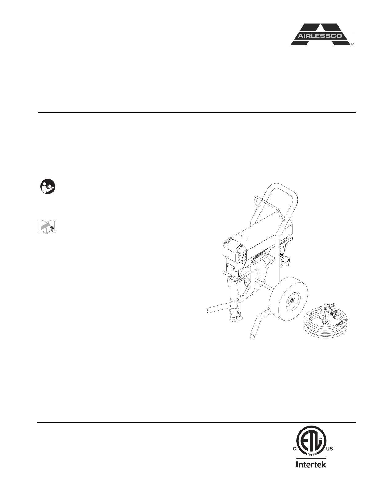
Airless Paint Sprayer
For application of architectural paints and coatings. For professional use only.
Airlessco - TS1500 (24F573) Series B
3300 psi (22.8 MPa, 228 bar) Maximum Working Pressure
Important Safety Instructions
Read all warnings and instructions in this
manual. Save these instructions.
Related Manuals
Gun Manual 3A0413
EN
ti17342a
Page 2
Warnings
Warnings
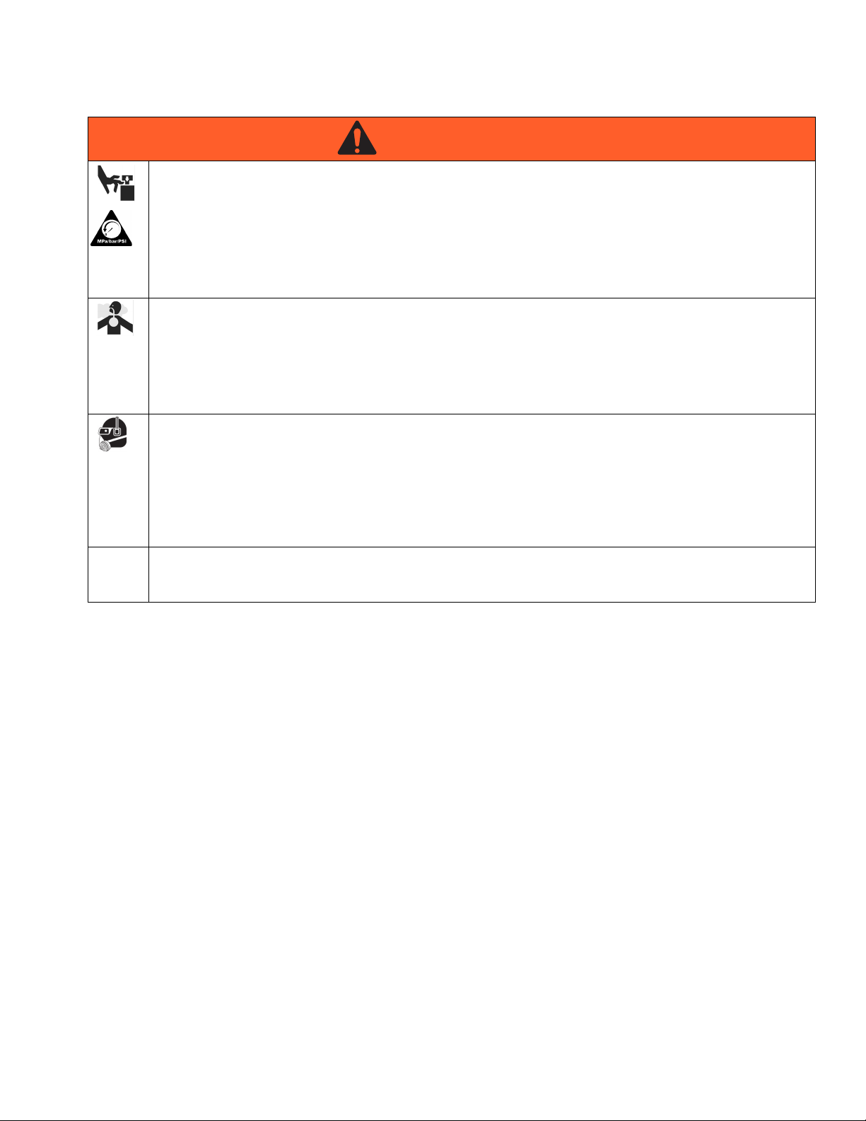
The following warnings are for the setup, use, grounding, maintenance, and repair of this equipment. The exclamation point symbol alerts you to a general warning and the hazard symbols refer to procedure-specific risks. When
these symbols appear in the body of this manual, refer back to these Warnings. Product-specific hazard symbols and
warnings not covered in this section may appear throughout the body of this manual where applicable.
WARNING
WARNINGWARNINGWARNING
GROUNDING
This product must be grounded. In the event of an electrical short circuit, grounding reduces the risk of
electric shock by providing an escape wire for the electric current. This product is equipped with a cord
having a grounding wire with an appropriate grounding plug. The plug must be plugged into an outlet that
is properly installed and grounded in accordance with all local codes and ordinances.
• Improper installation of the grounding plug is able to result in a risk of electric shock.
• When repair or replacement of the cord or plug is required, do not connect the grounding wire to either
flat blade terminal.
• The wire with insulation having an outer surface that is green with or without yellow stripes is the
grounding wire.
• Check with a qualified electrician or serviceman when the grounding instructions are not completely
understood, or when in doubt as to whether the product is properly grounded.
• Do not modify the plug provided; if it does not fit the outlet, have the proper outlet installed by a
qualified electrician.
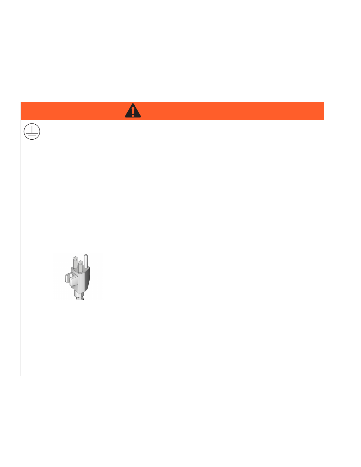
• This product is for use on a nominal 120V circuit and has a grounding plug similar to the plug
illustrated in the figure below.
• Only connect the product to an outlet having the same configuration as the plug.
• Do not use an adapter with this product.
Extension Cords:
• Use only a 3-wire extension cord that has a 3-blade grounding plug and a 3-slot receptacle that
accepts the plug on the product.
• Make sure your extension cord is not damaged. If an extension cord is necessary, use 12 AWG
(2.5 mm
• An undersized cord results in a drop in line voltage and loss of power and overheating.
2 3A1183D
2
) minimum to carry the current that the product draws.
Page 3
Warnings
WARNING
WARNINGWARNINGWARNING
FIRE AND EXPLOSION HAZARD
Flammable fumes, such as solvent and paint fumes, in work area can ignite or explode. To help prevent
fire and explosion:
• Do not spray flammable or combustible materials near an open flame or sources of ignition such as
cigarettes, motors, and electrical equipment.
• Paint or solvent flowing through the equipment is able to result in static electricity. Static electricity
creates a risk of fire or explosion in the presence of paint or solvent fumes. All parts of the spray
system, including the pump, hose assembly, spray gun, and objects in and around the spray area shall
be properly grounded to protect against static discharge and sparks. Use Graco conductive or
grounded high-pressure airless paint sprayer hoses.
• Verify that all containers and collection systems are grounded to prevent static discharge.
• Connect to a grounded outlet and use grounded extensions cords. Do not use a 3-to-2 adapter.
• Do not use a paint or a solvent containing halogenated hydrocarbons.
• Keep spray area well-ventilated. Keep a good supply of fresh air moving through the area. Keep pump
assembly in a well ventilated area. Do not spray pump assembly.
• Do not smoke in the spray area.
• Do not operate light switches, engines, or similar spark producing products in the spray area.
• Keep area clean and free of paint or solvent containers, rags, and other flammable materials.
• Know the contents of the paints and solvents being sprayed. Read all Material Safety Data Sheets
(MSDS) and container labels provided with the paints and solvents. Follow the paint and solvents
manufacturer’s safety instructions.
• Fire extinguisher equipment shall be present and working.
• Sprayer generates sparks. When flammable liquid is used in or near the sprayer or for flushing or
cleaning, keep sprayer at least 20 feet (6 m) away from explosive vapors.
ELECTRIC SHOCK HAZARD
This equipment must be grounded. Improper grounding, setup, or usage of the system can cause electric
shock.
• Turn off and disconnect power cord before servicing equipment.
• Use only grounded electrical outlets.
• Use only 3-wire extension cords.
• Ensure ground prongs are intact on power and extension cords.
• Do not expose to rain. Store indoors.
3A1183D 3
Page 4
Warnings
WARNING
WARNINGWARNINGWARNING
SKIN INJECTION HAZARD
High-pressure spray is able to inject toxins into the body and cause serious bodily injury. In the event that
injection occurs, get immediate surgical treatment.
• Do not aim the gun at, or spray any person or animal.
• Keep hands and other body parts away from the discharge. For example, do not try to stop leaks with
any part of the body.
• Always use the nozzle tip guard. Do not spray without nozzle tip guard in place.
• Use Airlessco nozzle tips.
• Use caution when cleaning and changing nozzle tips. In the case where the nozzle tip clogs while
spraying, follow the Pressure Relief Procedure for turning off the unit and relieving the pressure
before removing the nozzle tip to clean.
• Do not leave the unit energized or under pressure while unattended. When the unit is not in use, turn
off the unit and follow the Pressure Relief Procedure for turning off the unit.
• Check hoses and parts for signs of damage. Replace any damaged hoses or parts.
• This system is capable of producing 3300 psi. Use Airlessco replacement parts or accessories that are
rated a minimum of 3300 psi.
• Always engage the trigger lock when not spraying. Verify the trigger lock is functioning properly.
• Verify that all connections are secure before operating the unit.
• Know how to stop the unit and bleed pressure quickly. Be thoroughly familiar with the controls.
EQUIPMENT MISUSE HAZARD
Misuse can cause death or serious injury.
• Always wear appropriate gloves, eye protection, and a respirator or mask when painting.
• Do not operate or spray near children. Keep children away from equipment at all times.
• Do not overreach or stand on an unstable support. Keep effective footing and balance at all times.
• Stay alert and watch what you are doing.
• Do not leave the unit energized or under pressure while unattended. When the unit is not in use, turn
off the unit and follow the Pressure Relief Procedure for turning off the unit.
• Do not operate the unit when fatigued or under the influence of drugs or alcohol.
• Do not kink or over-bend the hose.
• Do not expose the hose to temperatures or to pressures in excess of those specified by Airlessco.
• Do not use the hose as a strength member to pull or lift the equipment.
PRESSURIZED ALUMINUM PARTS HAZARD
Use of fluids that are incompatible with aluminum in pressurized equipment can cause serious chemical
reaction and equipment rupture. Failure to follow this warning can result in death, serious injury, or
property damage.
• Do not use 1,1,1-trichloroethane, methylene chloride, other halogenated hydrocarbon solvents or
fluids containing such solvents.
• Many other fluids may contain chemicals that can react with aluminum. Contact your material supplier
for compatibility.
4 3A1183D
Page 5
Warnings
WARNING
WARNINGWARNINGWARNING
MOVING PARTS HAZARD
Moving parts can pinch, cut or amputate fingers and other body parts.
• Keep clear of moving parts.
• Do not operate equipment with protective guards or covers removed.
• Pressurized equipment can start without warning. Before checking, moving, or servicing equipment,
follow the Pressure Relief Procedure and disconnect all power sources.
TOXIC FLUID OR FUMES HAZARD
Toxic fluids or fumes can cause serious injury or death if splashed in the eyes or on skin, inhaled, or
swallowed.
• Read MSDSs to know the specific hazards of the fluids you are using.
• Store hazardous fluid in approved containers, and dispose of it according to applicable guidelines.
PERSONAL PROTECTIVE EQUIPMENT
You must wear appropriate protective equipment when operating, servicing, or when in the operating area
of the equipment to help protect you from serious injury, including eye injury, hearing loss, inhalation of
toxic fumes, and burns. This equipment includes but is not limited to:
• Protective eyewear, and hearing protection.
• Respirators, protective clothing, and gloves as recommended by the fluid and solvent manufacturer.
CALIFORNIA PROPOSITION 65
The engine exhaust from this product contains a chemical known to the State of California to cause
cancer, birth defects or other reproductive harm.
3A1183D 5
Page 6
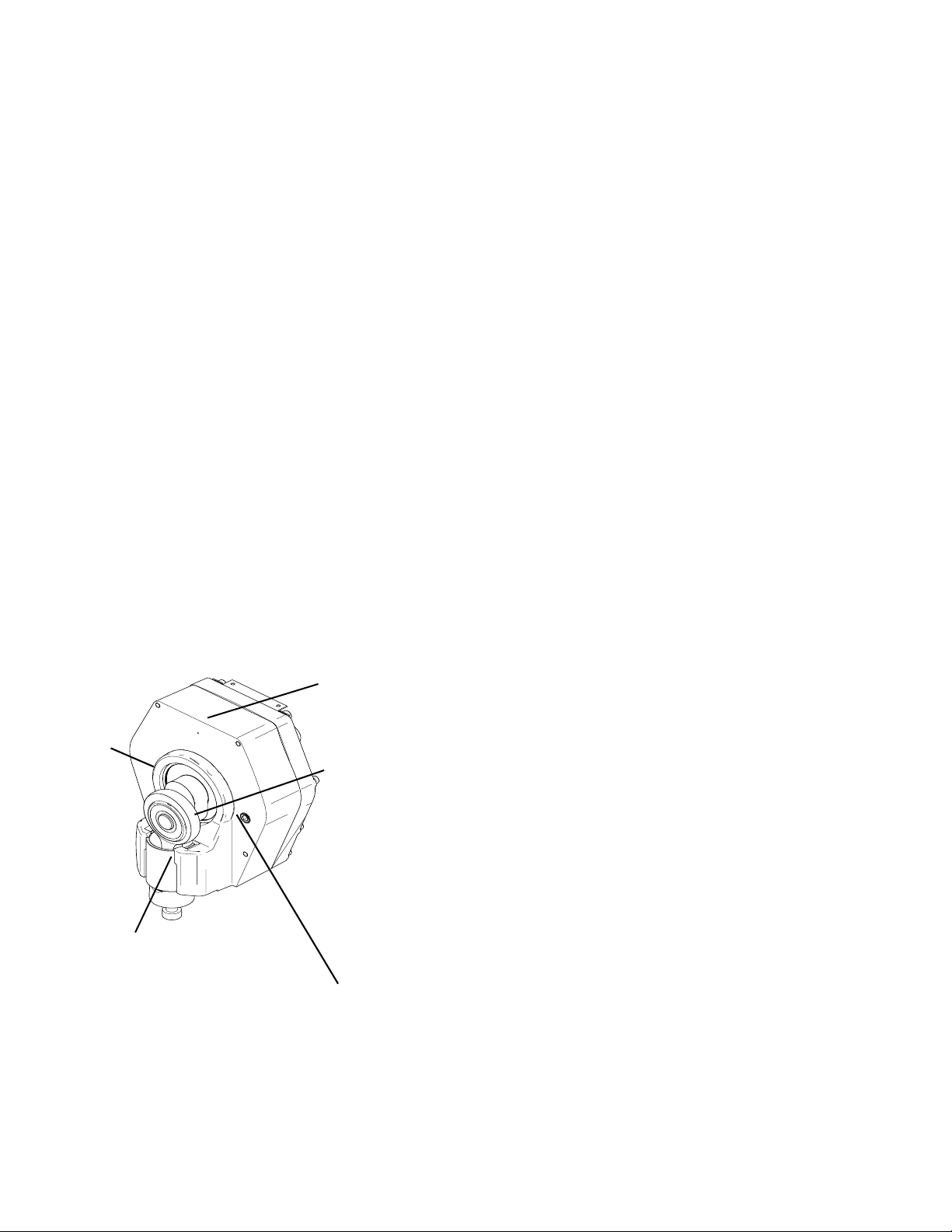
Component Identification
Component Identification
A
PRIME
D
B
PRESSURE
ti17939a
F
E
C
ti17343a
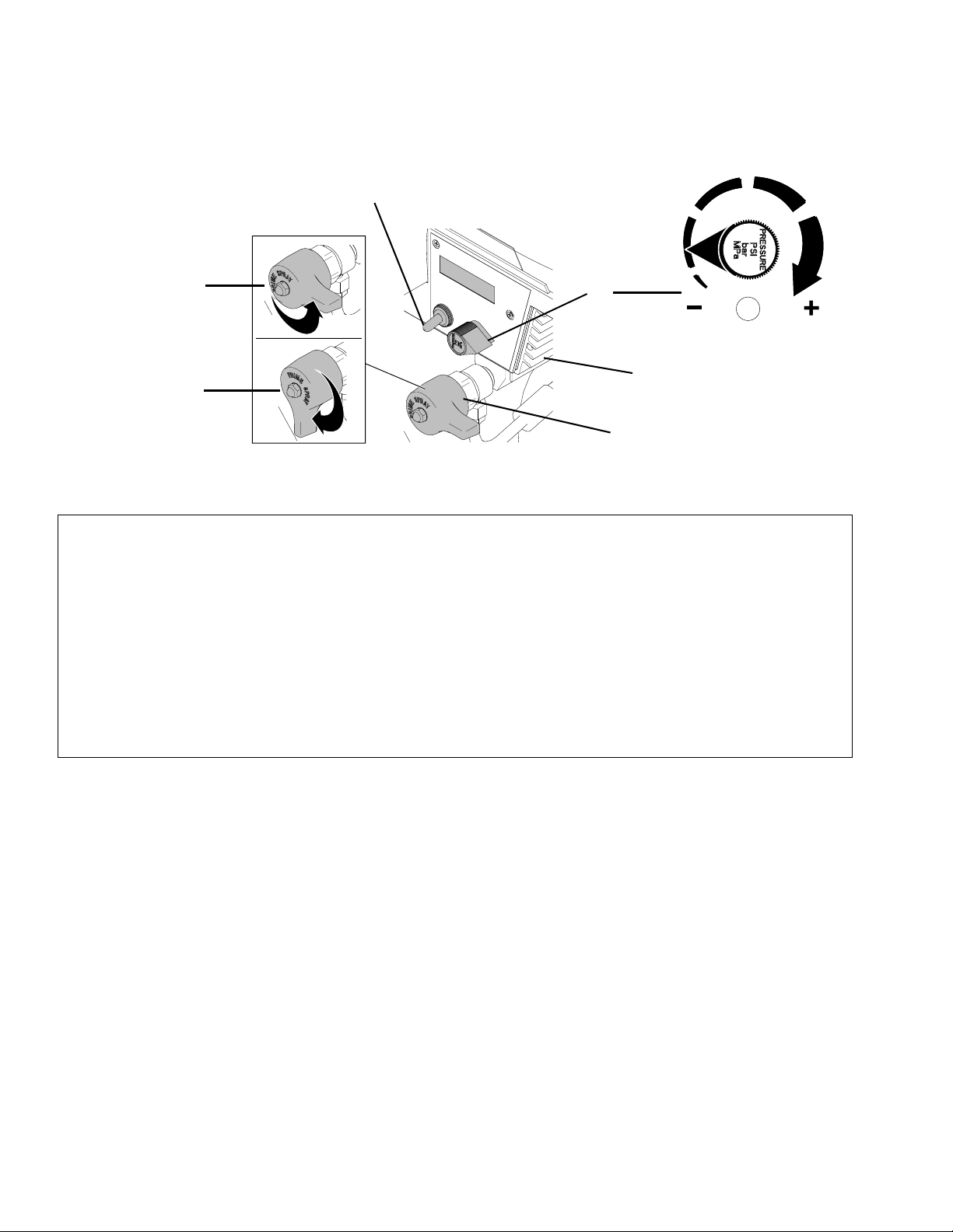
A Power switch Turns sprayer ON and OFF
B Pressure Control Knob Adjusts pressure. Turn clockwise to increase pressure and
counterclockwise to decrease pressure.
C Prime/Pressure Relief Valve Primes pump and relieves pressure from gun, hose and tip.
D Prime/Pressure Relief Valve Closed
Position
E Prime/Pressure Relief Valve Open
Position
Pressurizes system when closed.
Relieves pressure from gun, hose and tip and primes the unit
when in the open position. Refer to Pressure Relief Procedure
page 13
F Heatsink
6 3A1183D
Page 7
Operation
Operation
Setup
• To reduce the risk of static sparking, fire or
explosion which can result in serious bodily injury
and property damage, always ground the sprayer
and system components and the object being
sprayed, as instructed in the safety warning section
of this manual.
• Ensure electrical service is 120 VAC, 20 amp
minimum and the outlet is properly grounded.
• For generator power, a minimum 7000 watt
generator with a voltage regulation must be used.
Connect the hose and gun
1. Remove the plastic cap plug from the outlet and
screw a conductive or grounded 3000 psi spray
hose onto fluid outlet.
2. Connect an airless spray gun to the other end of the
hose. Do not install spray tip.
NOTE: Do not use thread sealer on swivel unions as
they are made to self seal.
Fill the Packing Nut/Wet Cup
Prime and Flush Storage Fluid
NOTICE
The equipment was tested with lightweight oil,
which is left in the fluid passages to protect parts.
To avoid contaminating your fluid with oil, flush the
equipment with a compatible solvent before using
the equipment for the first time.
Before beginning a new spraying project you need to
prime the sprayer and flush the storage fluid out of the
sprayer.
Oil- or Water-based Materials
• When changing from water-based material to oil
based material, flush with soapy water and then
mineral spirits.
• When changing from oil based material to water
base material, flush with mineral spirits, followed by
soapy water, then a clean water flush.
• When flushing with solvents, ground pail and gun.
• Flush before changing colors, before fluid can dry in
the equipment, at the end of the day, before storing,
and before repairing equipment.
Flushing
1. Fill the Packing Nut with 5 drops of ASM Packing
Seal Fluid.
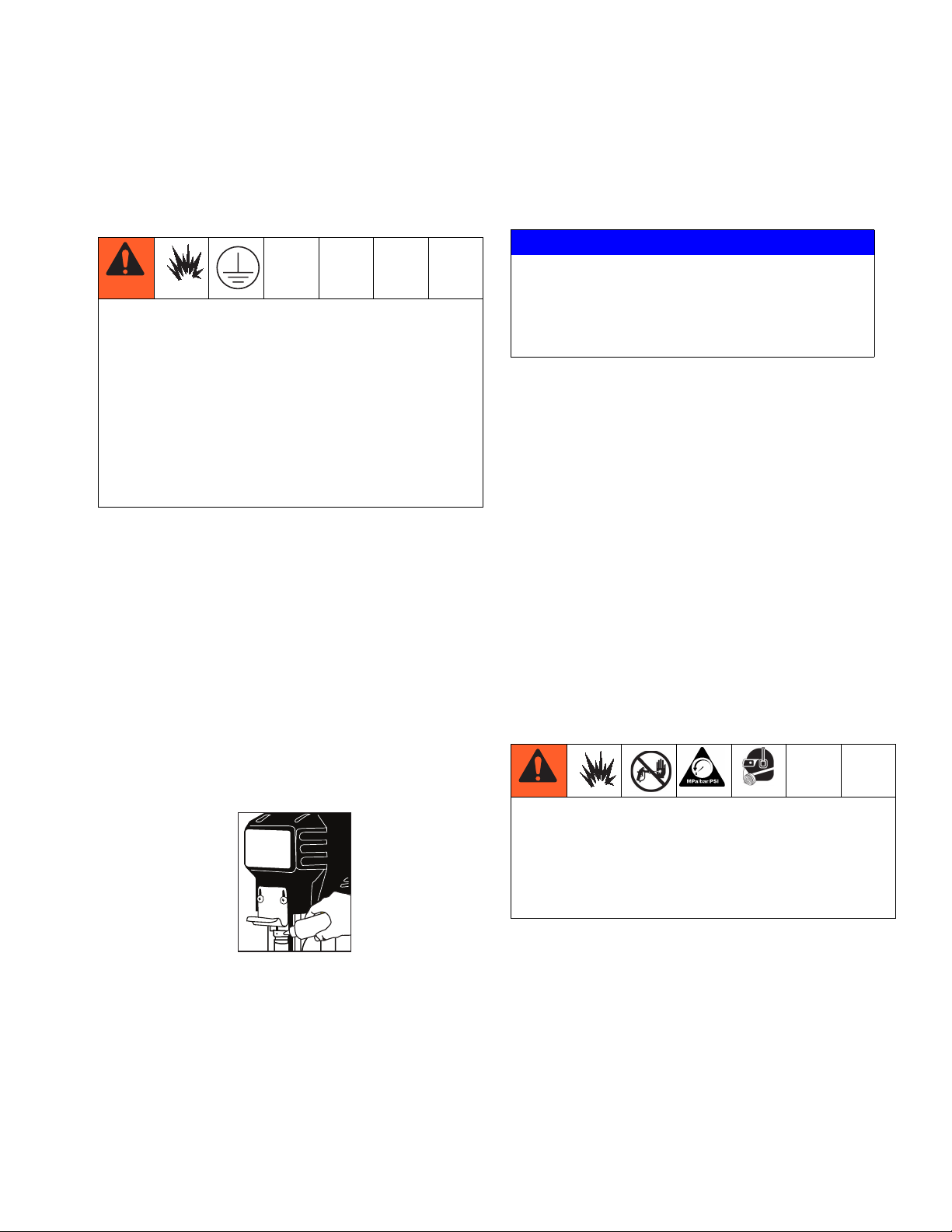
• To reduce the risk of static sparking, which can
cause fire or explosion, always hold a metal part of
the gun firmly against the metal pail when flushing.
This also reduces splashing.
• Always remove the spray tip before flushing.
ti15987a
1. Make sure the gun trigger lock in engaged and there
is no spray tip in the gun. Refer to the separate
Flush the Sprayer
1. Flush the sprayer. See Flushing Procedure on
page 7.
3A1183D 7
Page 8
Operation
instruction manual provided with gun for safety features and how to engage the trigger lock.
ti16028a
2. Pour enough clean, compatible solvent into a large,
empty metal pail to fill the pump and hoses.
3. Place the suction tube into the pail or place the pail
under the pump.
4. Turn Pressure Control Knob to low.
PRIME
HIGH PRESSURE
8. Allow the pump to operate until clean solvent comes
from the gun.
9. Release the trigger and engage the gun trigger lock.
10. If you are going to start spraying, place the pump or
suction tube into the supply container. Release the
gun trigger lock and trigger the gun into another
empty, metal container, holding a metal part of the
gun firmly against the metal pail, forcing the solvent
from the pump and hose. When paint starts coming
from gun, turn pressure control knob to minimum
pressure, place prime/pressure relief valve in prime
(open) position and engage the gun trigger lock.
11. If you are going to store the sprayer, remove the
suction tube or pump from the solvent pail, force the
solvent from the pump and hose. Engage the gun
trigger lock. See Storage, 9.
12. Whenever shutting down the sprayer, follow Pres-
sure Relief Procedure, page 13.
NOTICE
To prevent damage and freezing during storage,
never leave water in the fluid pump
ti17939a
PRESSURE
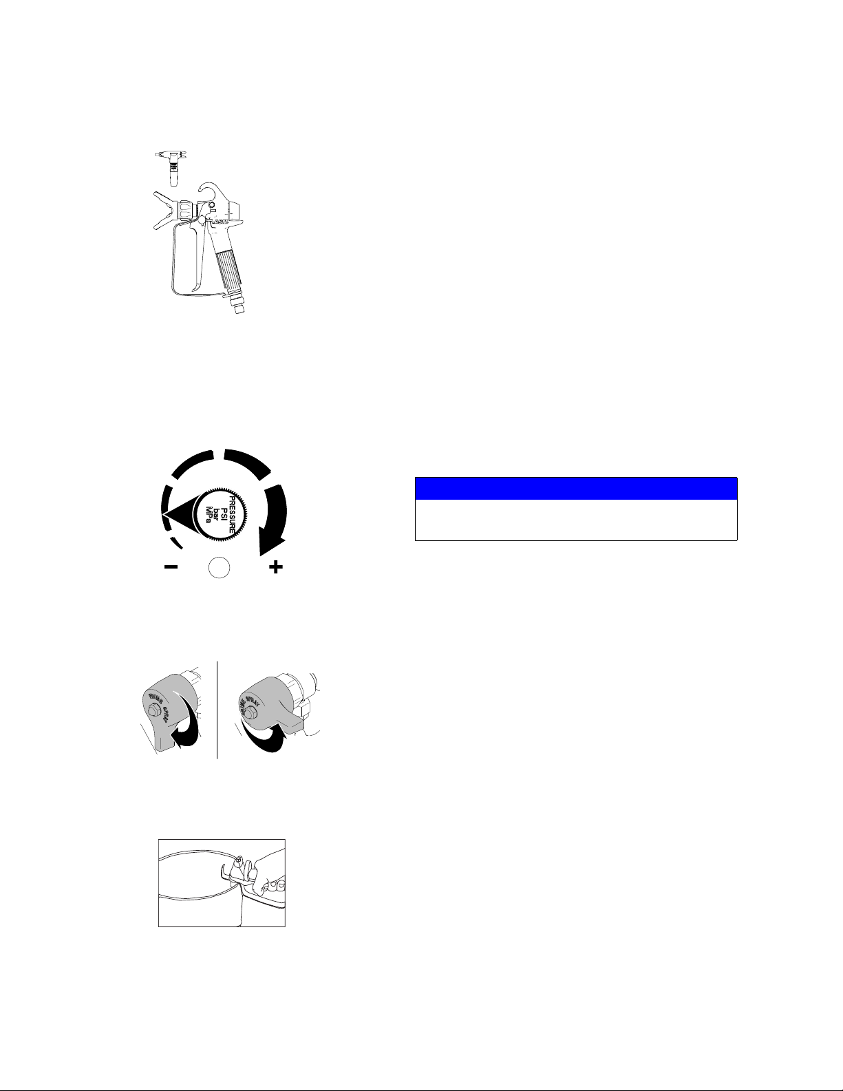
5. Open the Prime/Pressure Relief Valve to the open “Priming Position”. This will allow an easy start.
Open
(Priming and
Pressure Relief)
ti17402a
Closed
(Pressure)
6. Point the gun into the metal pail and hold a metal
part of the gun firmly against the pail. Maintain firm
metal to metal contact between gun and container.
ti15989a
7. Disengage the gun trigger lock and squeeze the
trigger. At the same time, slowly turn the pressure
control knob clockwise, just enough to move liquid
at low pressure.
Startup
1. Prepare the material according to the material manufacturer’s recommendations.
2. Place the suction tube into the material container.
3. Start the sprayer.
a. Prime/Pressure Relief Valve must be “OPEN”
in the priming position.
b. After ensuring the gun trigger lock is engaged,
attach tip and safety guard.
c. Turn the engine ON/OFF switch to the “ON”
position.
d. Turn the Pressure Control Knob clockwise to
prime the pump.
e. After the pump is primed, turn the Prime/Pres-
sure Relief Valve to the “CLOSED” position.
f. Turn Pressure Control Knob to the desired
spray pressure.
g. Disengage the gun trigger lock to begin spray-
ing.
8 3A1183D
Page 9

Operation
Adjusting the Pressure
• To reduce the risk of injection, never hold your
hand, body, fingers or hand in a rag in front of the
spray tip when cleaning or checking for a cleared
tip. Always point the gun toward the ground or into
a waste container when checking to see if the tip is
cleared or when using a self cleaning tip.
• When you spray into the paint bucket, always use
the lowest spray pressure and maintain firm metal
to metal contact between the gun and container.
• To stop the unit in an emergency, turn the engine
off. Then relieve the fluid pressure in the pump and
hose. See Pressure Relief Procedure, page 13
When adjusting the pressure, turn the Pressure Control
Knob clockwise to increase pressure and counterclockwise to decrease pressure. Always use the lowest pressure necessary to completely atomize the material. If
more coverage is needed, use a larger tip rather than
increasing the pressure.
NOTE: Operating the sprayer at higher pressure than
needed wastes material, causes early tip wear, and
shortens sprayer life.
Storage
Short Term
1. Flush sprayer with compatible solvent before storing, then fill the pump and hoses with an oil based
solvent such as mineral spirits or Graco or Airlessco
Pump Armor.
• For oil base paint: flush with mineral spirits
• For water-base paint: flush with water, then min-
eral spirits and leave the pump, hose and gun
filled with mineral spirits.
Long Term
For longer storage, use Graco or Airlessco Pump
Armor. Shut off sprayer, Relieve Pressure, page 13,
and make sure prime/pressure relief valve is left open.
Start Up After Storage
Before using water-base paint, flush sprayer with soapy
water and then a clean water flush. When using oil-base
paint, flush out the mineral spirits with the material to be
sprayed.
NOTE: Always store unit indoors.
NOTE: Check the spray pattern. The tip size and angle
determines the pattern width and flow rate.
Shutdown
1. Relieve Pressure, page 13.
2. Clean the tip and gun as recommended in the separate Gun Manual supplied with the gun.
3. If spraying water-based material or a material that
could harden in the sprayer overnight, flush the
sprayer after use. See Flushing, page 7.
Optional Air Atomizer
NOTICE
Atomizer must be cleaned after each use, any
debris will cause poor spray performance.
To eliminate the back flow of material into the air
system, always turn the air on first.
• For best performance use at least a minimum of 1
gallon per minute paint sprayer.
• For fog finish and fine orange peel use tip #13 or 16
and apply maximum air flow.
• For medium orange peel and splatter coat, use tip
#14 or 17 and apply medium air flow.
• For heavy splatter coat and knockdown finish use
tip #15 or 17 and apply less air flow.
3A1183D 9
Page 10
Maintenance
-
Maintenance
Regular Maintenance
1. Always stop the pump at the bottom of its stroke
when you take a break or at the end of the day. This
helps keep material from drying on the rod, damaging the packings.
2. Keep displacement pump packing nut/wet cup 1/3
full of Airlessco Throat Seal Oil at all times. The
TSO helps protect the packings and rod.
3. Lubricate Connecting Rod Pin every 3 months.
Daily Maintenance
Inspect the packing nut daily. If seepage of paint into the
packing nut and/or movement of the piston upward is
found (while not spraying), the packing nut should be
tightened just enough to stop leakage. Overtightening
will damage the packings and reduce the packing life.
Oil and Lubrication Instructions
Electric Motor Maintenance
Lubrication
The motor is supplied with pre-lubricated ball bearings,
lubricated for the life of the bearing.
Motor Brushes
Motor brushes need periodic inspection and replacement as wear indicates. Brushes have an initial length of
1 and 1/4” and should be replaced when they are worn
to a length of 5/8”. Brush wear is greatly influenced by
individual application and it is recommended that brush
wear be checked at early intervals of operation in order
to determine future required inspection.
To change the brushes:
1. Unplug the machine.
2. Remove the cover over the motor.
3. Open the two covers at the rear of the motor.
Sealed
Bearing
Oil impregnated sleeve - dip in
hot 10W oil when removed
Fill plug- unit has grease in gearbox from factory
and will not require changing. (Grease - PN
301178)
Bleed (Weep Hole)
1 oz. SAE 30W Oil
semi-annually
ti15992a
4. Loosen the screw under the brush.
5. Pull out the wire.
6. Push the brush retainer clip in and withdraw.
7. Remove the worn brushes.
8. Install new brushes in the reverse order.
To increase brush life, new brushes (Part #301146 for
110 volt) need to have a run in period. After changing
brushes, set the machine for spraying. With a bucket of
Pump Conditioner and water, a 50’ 1/4” airless hose, airless gun and tip on unit, open the prime/pressure relief
valve and switch on. The pump will now prime. With
pump running in the prime mode, turn the pressure control knob to high pressure. (The pump has to cycle fast
with no pressure in the pump). Run the pump for 20 minutes and the brushes will be run in.
10 3A1183D
Page 11
Maintenance
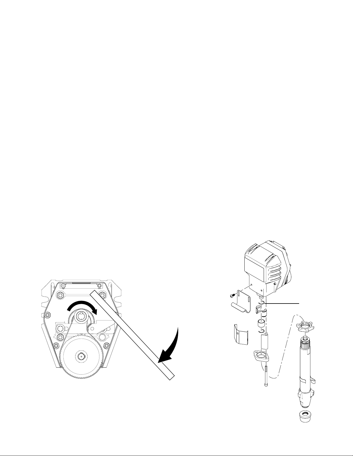
Replacement of Belt/Belt Adjustment
NOTE: The Cog Belt System does not require align-
ment. When upper sheave is placed on motor shaft it is
pushed on until a positive stop is reached. The set
screws are then loctited. The lower pulley is placed on
gearbox and held in place with keyway and snap ring.
The flange on upper sheave holds the belt in alignment
and the belt self aligns on lower pulley eliminating having to align.
1. Remove cover from unit.
2. Remove tensioner Assembly. Loosen screws. Move
gearbox forward to allow removal and replacement
of belt.
3. Retighten screws into gearbox until they bottom out.
This will align gearbox correctly.
4. Replace tensioner with bolts and leave loose to
allow adjusting belt tension.
5. Tighten belt. When properly tightened the deflection
play should be 1/4 inch when pushing hard with
thumb. (20 ft/lbs)
NOTE: When placing belt on pulleys and inserting the
tensioner against belt, ensure cogs on belt are engaged
into cogs on pulleys before tightening belts. Rotating
upper pulley while holding the tensioner against the belt
will allow proper engagement of cogs prior to tightening.
Servicing the Fluid Pump
NOTE: Before disassembling the sprayer refer to Trou-
bleshooting to try and resolve the problem.
Fluid Pump Disconnect
1. Flush out the material you are spraying, if possible.
2. Relieve Pressure, page 13. Stop the pump in the
middle of down stroke.
3. Remove the suction tube and fluid hose (if so
equipped) from the fluid pump.
4. Remove the connecting rod shield from the pump.
5. Remove two retaining rings (6), slip the sleeve of
the coupling down, and remove both coupling
halves. This will disconnect fluid pump from the connecting rod.
6. Using a 7/8” box wrench, disconnect the high pressure fluid line from the pump.
7. Using a 9/16” wrench, unscrew the two tie rod locknuts.
8. Pull the pump off the tie rods.
6
ti16032a
ti16033a
3A1183D 11
Page 12

Maintenance
Fluid Pump Reinstall
1. Loosen the packing nut and extend piston rod to
fully up position. Slip sleeve over the piston rod.
ti15994a
2. Insert one of the retaining rings through the packing
nut and rest the sleeve on top of it.
ti15995a
ti15996a
3. Connect the connecting rod with the fluid pump by
installing the coupling halves. Slide sleeve over the
coupling halves and secure with retaining rings.
4. Remove the retaining ring from the packing nut and
insert into coupling halves.
ti15998a
5. Secure the fluid pump housing to the tie rods and
screw locknuts with washers on loosely.
6. Tighten the tie rod locknuts evenly to 30 ft. lb.
NOTE: After all the rod locknuts are tight, the alignment
of both rods should allow easy assembly and disassembly of the coupling. If any binding, loosen and retighten
all the rod locknuts to improve the alignment. Misalignment causes premature wear of seal and packings.
7. Tighten packing nut clockwise until resistance
against the packings can be felt. Turn it one full turn
more.
8. Start the pump and operate it slowly (at low engine
speed) to check the piston rod for binding. Adjust tie
rod lock nuts if necessary to eliminate binding.
9. Prime the unit and run at maximum pressure for
several minutes, then release the pressure and
repeat step 6.
10. Fill the wet cup (packing nut) with five drops of TSO
(Throat Seal Oil).
ti15997a
12 3A1183D
Page 13

Service
Maintenance
Pressure Relief Procedure
Follow the Pressure Relief Procedure whenever
you see this symbol.
This equipment stays pressurized until pressure is
manually relieved. To help prevent serious injury from
pressurized fluid, such as skin injection, splashing
fluid and moving parts, follow the Pressure Relief
Procedure when you stop spraying and before
cleaning, checking, or servicing the equipment.
1. Engage gun trigger lock.
2. Turn ON/OFF switch to OFF.
3. Unplug power cord.
4. Disengage gun trigger lock. Hold metal part of gun
against grounded metal pail and trigger gun into pail
to relieve pressure.
5. Engage gun trigger lock.
6. Open any fluid prime/pressure relief valves in system. Leave prime/pressure relief valve open until
ready to dispense again.
Cleaning and Inspecting Parts
• Never use sharp or pointed tools to remove sleeve
or other components which could result in pump
rupture and cause serious bodily injury. If the
sleeve cannot be removed easily, return the sleeve
and cylinder to your Graco/Airlessco distributor for
removal.
1. Clean and inspect parts. Pay particular attention to
the ball seats in the intake valve and piston, which
must have no nicks or wear, and the inside of the
sleeve and the outside of the piston rod, which must
not be worn or scratched. Replace worn or damage
parts.
2. Remove and clean the sleeve when you are repacking the pump.
Repair When Pump is Off the Sprayer
Disassembling the pump
1. Remove packing nut (202) and throat adjustment
spacer (228).
202
Tools Needed
•Vise
• 12” adjustable open end wrench (2)
• Hammer, 20 oz maximum
• Small screwdriver
• Throat Seal Liquid
• Pick or long small screwdriver
3A1183D 13
228
7568a
Page 14

Maintenance
2. Unscrew intake valve from cylinder.
7569a
3. Disassemble intake valve. Clean and inspect.
O-ring (227) may require a pick for removal.
227
5. Remove piston rod from sleeve, or remove sleeve
from cylinder.
7572a
6. Unscrew piston valve from piston rod. Clean and
inspect parts. The piston has a special thread locking/sealing patch. Do not remove the patch. The
patch allows for disassembly/assembly procedures
before it is necessary to apply Loctite
®
to the
threads.
7570f
4. Tap piston rod out of cylinder with a hammer or flip
over and tap piston rod against a bench.
NOTE: Sleeve may come out of cylinder with piston rod.
7571a
7576a
7. Remove packings and glands from piston rod.
ti3940b
14 3A1183D
Page 15

Maintenance
8. Remove throat packings and glands from cylinder.
Discard throat packings and glands.
75736b
Assembling the pump
1. Soak all leather packings in SAE 30W oil for 1 hour
minimum prior to assembly. Stack male gland (204)
on piston rod. Alternately stack UHMWPE (208) and
leather (218) packings (note orientation) and
backup washer (229) on piston valve (210). The
special sealing patch on piston valve threads is
good for four repackings. Use Loctite
®
on piston
valve threads after four repackings.
2. Install ball (206) in piston rod. If Loctite is applied to
piston valve threads, ensure that none gets on ball.
206
7575a
3. Tighten piston valve to piston rod as specified.
210
229
216
7576a
217
204218
208
7574d
3A1183D 15
Page 16

Maintenance
4. Soak all leather packings in SAE 30W oil for 1 hour
minimum prior to assembly. Place male gland (204)
in cylinder. Alternately stack (UHMWPE (203) and
leather packings (223) (note orientation). Place
female gland (224) in top of cylinder. Seat packings.
224
203
223
204
7573f
5. Install seal (201) into packing nut (202), Install
throat adjustment spacer (228) onto packing nut.
Loosely install packing nut into cylinder.
6. Grease piston packings.
7578c
NOTICE
Do not slide piston assembly into top of sleeve as
this may damage piston packing.
7. Slide piston assembly into bottom of sleeve.
202
201
228
7577a
8. Grease top inch or two of piston rod that will go
through the cylinder throat packings.
7581a
7579a
9. Grease O-rings (221) and place on sleeve. Slide
sleeve/piston rod assembly into bottom of cylinder.
Replace O-ring (207) if desired.
16 3A1183D
Page 17

Maintenance
NOTE: O-ring (207) is not required for safe pump operation.
207
221
7582a
10. Reassemble intake valve with new O-ring (227),
seat (212) and ball (214), Seat may be flipped over
and used on other side. Clean seat thoroughly.
214
212
Remove throat adjustment spacer (228) when pump
packings begin to leak after much use. Then tighten
packing nut down until leakage stops or lessens. This
allows approximately 100 gallons of additional operation
before a repacking is required.
202
228
7568a
Replacement of Electrical Components
227
7570f
11. Install intake valve on cylinder. If a wrench is used
torque as follows:
• 80 +/-5-ft-lb
If a wrench is not used, be sure intake valve is bottomed
out against cylinder.
7569a
12. Torque packing nut (202) down onto adjustment
spacer (228) 100 +/-10 in-lb.
Always unplug the electrical cord before servicing the
machine.
Pressure Control Assembly (Electrical
Control Board)
1. Unplug machine’s power cord.
2. Remove screws and lower the pressure control
assembly.
3. Disconnect all leads from pressure control assembly.
4. Reassemble in reverse order.
Sensor
1. Remove the screws and lower the pressure control
assembly.
2. Disconnect sensor lead from the board.
3. Unscrew sensor from pressure control assembly
using a 3/4” wrench.
4. Reassemble in reverse order. Use PTFE tape on
the sensor threads prior to reinstalling it into the
pressure control assembly.
3A1183D 17
Page 18

Maintenance
Potentiometer
1. Lower pressure control assembly as described
above.
2. Disconnect potentiometer lead from pressure control assembly.
3. Use a 1/16” allen wrench, loosen set screw in the
poteniometer knob and remove knob and spacer.
4. Using a 1/2” wrench or deep socket, remove the nut
from the potentiometer shaft assembly.
5. Pull entire potentiometer assembly out of the frame.
6. Replace in reverse order.
On-Off Toggle Switch
1. Lower the pressure control assembly as described
above.
2. Disconnect the two wires on the toggle switch.
3. Use a 9/16” wrench to loosen the nut on the toggle
switch shaft.
Liquid Crystal Display (LCD)
1. Ensure the power switch is OFF and the machine is
unplugged.
2. Detach the pressure control assembly from the
frame by unscrewing the two screws.
3. Disconnect the LCD lead from the pressure control
assembly.
4. Separate the LCD assembly from the frame by
undoing the eight screws.
5. Disassemble LCD from the control by removing the
retaining screws.
6. Remove and replace LCD Display.
7. Reassemble in reverse order.
NOTE: Do not over tighten the screw and nuts. This can
warp the LCD and damage it.
4. Reassemble in reverse order.
ti17332a
18 3A1183D
Page 19

Troubleshooting
General
Problem Cause Solution
Unit doesn’t prime Airleak due to loose suction nut Tighten suction nut.
Airleak due to worn o-rings Replace o-ring on suction seat and o-ring
below suction seat.
Stuck or fouled balls Service inlet and outlet valves.
Troubleshooting
Prime/Pressure Relief valve not
opening
Unit primes but has poor or no
pressure
Unit does not maintain good
spraying pressure
Unit does not run See Machine Does Not Start
Machine does not start Control Settings Make sure machine is plugged into the wall.
Pressure set too low Turn up pressure.
Filter(s) are clogged Clean or replace gun filter, inlet filter, and/or
Outlet valve fouled/worn. Service outlet valve.
Prime/pressure relief valve
bypassing
Packings and/or piston worn Tighten packing nut, repack unit.
Blown spray tip Replace spray tip.
Packings and/or pistons worn Repack unit.
Upper seat worn Replace upper seat.
Pressure Control Assembly
(Board)
Clean or replace Prime/Pressure Relief Valve
manifold filter.
Clean or replace Prime/Pressure Relief Valve
Verify the on-off switch is in the ON position
and the pressure control knob is turned all the
way to the right (clockwise for maximum pressure).
If the power indicating light is still out after
checking the control settings and power
source, replace the pressure control assembly.
3A1183D 19
Page 20

Troubleshooting
Problem Cause Solution
Motor Remove the motor brush covers and turn the
machine ON. Set the potentiometer (POT) at
maximum pressure and check for DC voltage
across both brush terminals. It should read
greater than 80 volts DC.
If you have DC voltage, turn the machine off
and unplug it from the wall. Check to make
sure the brushes are making good contact
with the armature. Replace the brushes if they
are less than 5/8” long. If the brushes are
good, replace the motor.
If you do not have DC voltage, see Sensor.
Sensor Plug another sensor board into the board and
perform the zero calibration procedure. If the
machine starts to run, the sensor is bad. If
there is no replacement sensor available, use
a multi-meter to test the resistance across the
red and black wires of the sensor (be sure to
test the plug). You should read 1.5 - 3.5k
ohms. A faulty sensor usually reads no continuity (open).
Pressure Control Knob (Potentiometer)
If the sensor passes all the tests, see Pres-
sure Control Knob (Potentiometer).
Plug another potentiometer (POT) into the
control board. If the machine starts, the old
POT is bad.
When a replacement POT is not available,
remove the POT lead (with the machine
turned off) from the control board and test the
resistance between the red and black wires
(be sure to test at the plug). The resistance
should read between 8-12k ohms. If it is outside of this range replace the POT.
If there is DC voltage at the motor brushes
and the sensor and pressure control knob are
functioning, replace the pressure control
assembly.
20 3A1183D
Page 21

Pressure Control Repair
Motor Control Board Diagnostics
Troubleshooting
1. For sprayers with digital display, seeDigital Display
Messages, page 22
Relieve pressure and unplug sprayer before servicing
control board. See Pressure Relief Procedure,
page 13.
NOTE: Keep a new transducer on hand to use for test.
NOTICE
Do not allow sprayer to develop fluid pressure without transducer installed. Leave prime/pressure relief
valve open if test transducer is used.
LED
BLINKS
Once Sprayer runs Normal operation Do nothing
Two times
repeatedly
Three times
repeatedly
SPRAYER OPERATION INDICATES WHAT TO DO
Sprayer shuts down and
LED continues to blink two
times repeatedly
Sprayer shuts down and
LED continues to blink four
times repeatedly.
Run away pressure. Pressure
greater than 4500 psi (310 bar,
31 MPa) or damaged pressure
transducer.
Pressure transducer is faulty or
missing
2. Remove screws and cover.
3. Turn ON/OFF switch ON.
4. Observe LED operation and reference following
table:
Replace motor control board or
pressure transducer.
Check transducer connection.
Open prime/pressure relief valve.
Substitute new transducer for
transducer in sprayer. If sprayer
runs, replace transducer.
Four times
repeatedly
Five times
repeatedly
Six times
repeatedly
Eight times
repeatedly
3A1183D 21
Sprayer shuts down and
LED continues to blink four
times repeatedly.
Sprayer does not start or
shuts down and LED continues to blink five times
repeatedly
Sprayer shuts down and
LED blinks six times
repeatedly
Sprayer stops or does not
run
Line voltage is too high Check for voltage supply prob-
lems
Motor fault Check for locked rotor, shorted
wiring or disconnected motor.
Repair or replace failed parts.
Motor is too hot or there is a
fault in the motor thermal
device
High input voltage Check power source for correct
Allow sprayer to cool. If sprayer
funs correctly when cool, check
motor fan function and air flow.
Keep sprayer in cool location. If
sprayer does not run when cool
and continues to blink 6 times,
replace motor.
voltage
Page 22

Troubleshooting
Digital Display Messages
No display does not mean that spayer is not
pressurized. Relieve pressure before repair. See
Pressure Relief Procedure, page 13
DISPLAY SPRAYER OPERATION INDICATION ACTION
No Display Sprayer stops. Power is
not applied. Sprayer may
be pressurized.
Sprayer is pressurized.
Power is applied. (Pressure varies with tip size
and pressure control setting.)
Sprayer may continue to
run. Power is applied.
Sprayer stops. Power is
applied.
Sprayer stops. Power is
applied.
Sprayer does not start or
stops. Power is applied.
Loss of power. Check power source. Relieve
pressure before repair or disassembly.
Normal operation Spray
Pressure greater than 4500 psi
(310 bar, 31 MPa) or pressure
transducer faulty
Pressure transducer faulty, bad
connection or broken wire.
Line voltage too high. Check for voltage supply problem
Motor fault Check for locked rotor, shorted
Replace pressure control board or
pressure transducer
Check transducer connection.
Open prime/pressure relief valve.
Substitute new transducer for
transducer in sprayer. If sprayer
runs, replace transducer.
wiring or disconnected motor.
Repair or replace failed parts.
Sprayer stops. Power is
applied.
Power is applied. Pressure less than 200 psi (14
Sprayer stops or does not
run.
22 3A1183D
Motor is too hot. Allow sprayer to cool. If sprayer
runs correctly when cool, check
motor fan function and air flow.
Keep sprayer in cool location. If
sprayer does not run when cool
and continues to blink 6 times,
replace motor.
Increase pressure if desired.
bar, 1.4 MPa)
High input voltage Check power source for correct
Prime/pressure relief valve may
be open.
voltage.
Page 23

Troubleshooting
Airless Spray Gun
Problem Cause Solution
Coarse spray Low pressure Increase the pressure
Excessive fogging (overspray) High pressure Reduce the pressure to satisfactory pattern
distribution.
Material too thin Use less thinner
Pattern too wide Spray angle too large Use smaller spray angle tip
Pattern too narrow Spray angle too small Use larger spray angle tip (if coverage is OK,
try tip in same tip group)
Too much material Nozzle too large Use smaller tip
Material too thin Use smaller tip
Pressure too high Reduce pressure
Too little material Nozzle too small Use next larger tip
Material too thick
Thin distribution in center of
pattern “horns”
Thick skin on work Material too viscous Thin cautiously
Coating fails to close and
smooth over
Spray pattern irregular,
deflected
Craters or pock marks, bubbles on work
Clogged screens Extraneous material in paint Clean screen
Worn tip Change to new tip
Wrong tip Use nozzle with narrow spray angle
Application too heavy Reduce pressure and/or use tip in next
smaller tip size
Material too viscous Thin cautiously
Orifice clogged Clean carefully
Tip damaged Replace with new tip
Solvent balance Use 1 to 3% “short solvents remainder “long”
solvents (this is most likely to happen with
material of low viscosity, lacquers, etc.)
Course pigments Use coarse screen if orifice size allows.
Poorly milled pigments (paint
pigments glocculate)
Use courser screen, larger orifice tips. Obtain
ball milled paint. If thinner had been added,
test to see if a cover screen. Incompatible
drop placed on top of paint mixes or flattens
out on the paint mixture and thinners on the
surface. If not, try different thinner in fresh
batch of paint.
Excess paint builds on tip
guard
Drips, spits from tip Valve seat and/or ball in gun
3A1183D 23
Spray gun too close to surface Hold gun further from surface sprayed
Pressure setting too high Reduce pressure setting
Service spray gun, replace valve assembly
head damaged or worn
Page 24

Troubleshooting
Problem Cause Solution
Tip clogs continually Debris in paint Thoroughly strain the paint before use
Gun filter missing Do not operate without inlet strainer
Coarse filter mesh Do not operate without inlet strainer
Test the Pattern
Spotty Pattern,
Good, Full
Increase Pressure
ti15991a
24 3A1183D
Page 25

Parts
Optional Manifold Kit (301440)
Parts
1
10
11
3
4
5
8
9
6
Optional Filter Kit (866123)
12
ti16036a
Ref. Part Description Qty.
1 866123 FILTER, ASSY 1
3 867188 FITTING, ELBOW STREET 90 3/8
2
NPT
4 867309 FITTING, NIPPLE, 3/8 NPT to 1/4
2
NPT
5 866445 SPACER, .377 ID x .40 LG AL 2
6 305140 BRACKET - FILTER 1
7 867534 SCREW 5/16-18 x 1.00 PH HD
2
(not shown)
8 331103 WASHER .562 .250 .060 .ST 2
9 121112 SCREW, CAP, SOCKET HEAD 2
10 867400 HOSE PAINT, 3/8”x21” LG 1
11 557391 PLUG, 1/4 NPT 1
12 866052 CAP PLUG SET, .25 1
1
2
3
Ref. Part Description Qty.
1 867145 BASE 1
2 301356 SPRING 1
4
3 867377 O-RING 1
4 867214 FILTER 60 MESH 1
5 867647 SUPPORT 1
6 867077 BASE 1
7 867420 PLUG (3/8”) NPT PLATED 1
5
6
ti16037a
7
3A1183D 25
Page 26

Parts
Frame Parts Diagram
64
59
38
28
23
24
34
32
20
56
8
4
62
132
25
114
27
22
31
14
96
16
Ref Part Description Qty.
4 342425 LABEL - HIGH VOLTAGE 1
8 LABEL,DESIGNATION 1
14 867791 FRAME,CART 1
16 301134 PLUG,NEOPRENE 2
17 143029 COLLAR,SCREW,SET (SPECIAL ID) 2
18 301165 WHEEL,PNEUMATIC 2
19 866025 AXLE 1
20 116167 KNOB,POTENTIMETER 1
22 DISPLAY,LCD 1
23 867798 DISPLAY,WINDOW 1
24 867816 SCREW,MACH,PHILLIPS FLAT HD 2
25 117281 SPACER,#6 X .312 2
27 867817 NUT,HEX 2
28 867803 LABEL,CONTROLS,SL 1
31 301083 SWITCH,TOGGLE 1
32 301150 BOOT,RUBBER,BLACK 1
19
18
82
ti 17876a
17
ti17476a
Ref Part Description Qty.
34 256219 POTENTIOMETR,ASSEMBLY 1
38 866049 CABLE,ASSY 9” LG 1
59 110637 SCREW,MACH,PANHEAD 13
62 867252 GROMMET 1
82 HSE3850 HOSE, 3/8” x 50
255439 HOSE, CPLD, 1/4” x 3’
96 24F690 GUN MASTIC, MASTIC
114 867731 WASHER,PLAIN-1/8IN.IDX5/16IN. 2
867821 DISPLAY KIT (includes 22, 23, 24,
25, 27, 114)
Additional warning labels are available at no cost.
26 3A1183D
Page 27

Motor and Drive
Parts
10
93
94
54
53
4949
52
66
65
5050
51
46
64
13
61
70
79
115
60
71
7777
63
76
72
43
73
69
80
75
74
58
12
5
60
59
55
6
57
67
65
68
78
81
84
48
3A1183D 27
44
47
45
41
42
83
85
ti17477a
Page 28

Parts
Motor and Drive Parts List
Ref. Part Description Qty
5 342473 LABEL GENERAL WARNING 1
6 342506 LABEL NEVER/ALWAYS LP&SL 1
10 16F596 LABEL,AIRLESSCO, TS1500,
FRONT
12 16F597 LABEL,AIRLESSCO, TS1500,
RIGHT
13 16F598 LABEL,AIRLESSCO, TS1500, LEFT 1
41 189920 STRAINER,(1-11 1/2 NPSM) 1
42 198542 CLIP,SPRING 1
43 193031 NUT,RETAINING 1
44 16C304 PLATE,PUMP 1
45 24E349 PUMP,DISPLACEMENT 1
46 16C792 SPACER,SL SERIES 2
47 124125 SCREW,CAP,SOC,3/8X4.25 2
48 301467 SHIELD FRONT SL SERIES 1
49 867140 COUPLER, 2
50 867468 RETAINER,RING,EXTERNAL,1.00 2
51 866069 COVER,COUPLING 1
52 301204 BOX,GEAR (Includes 52a, 52b, 52c) 1
52a 301046 ROD END (not shown) 1
52b 301333 CONNECTING ROD ASSEMBLY
(not shown)
52c 301047 SLEEVE BEARING (not shown) 1
53 301320 COVER 1
54 121112 SCREW,CAP, SOCKET HEAD 4
55 331163 CORD,POWER, USA ASSY 1
57 301106 MOTOR 1
58 301321 COVER 1
59 110637 SCREW,MACH,PANHEAD 13
60 301135 GROMMET 6
61 865180 TRIM,EDGE, RUBBER 2
Ref. Part Description Qty
63 301193 BRACKET,TENSIONER 1
64 100057 SCREW,CAP,HEX HD 2
65 100214 WASHER,LOCK 6
1
66 867704 WASHER,PLAIN, 5/16 NOMINAL 2
67 111303 NUT,HEX 4
1
68 140029 WASHER,PLAIN 4
69 100307 NUT,HEX 3
70 301044 SCREW,MODIFIED 3
71 301099 RETAINER,5/8-18 3
72 866455 PULLEY,69 TEETH, MACHINING 1
73 301231 BELT,TIMING,5MM PITCH 1
74 301139 KEY,WOODRUFF, 3/16 X 5/8 1
75 867461 RETAINER,RING, EXTERNAL,.625 1
76 866212 KEY,SQUARE,3/16 X 1.35 1
77 101118 SCREW 2
78 866452 GEAR,SHEAVE 1
79 557391 PLUG,DRYSEAL 1/4 NPTF 1
80 867311 FITTING,NIPPLE HX 3/8 TO 3/8
NPT
81 301308 HOSE,3/8 X 16 LONG 1
83 867758 HOSE,DRAIN 1
1
84 867759 CONNECTOR,MALE,3/8 TUBE X
1/8 PIPE
85 241920 DEFLECTOR,THREADED 1
93 867529 SCREW 5/16-18 X .75 PH HD 2
94 301105 HOOK 1
115 110037 SCREW,MACH,PNH 2
867206 FAN - NWU (Not Shown)
867208 FAN COVER - NWU (Not Shown)
Additional warning labels are available at no cost.
1
2
28 3A1183D
Page 29

TS1500 Pump Parts Diagram
Parts
24
25
23
Ref. Part Description Qty.
1 196753 HOUSING, VALVE, INTAKE 1
5
3
2
10101010
2 CYLINDER, PUMP 1
3 193032 NUT. PACKING 1
4 248210 SLEEVE, CYLINDER 1
5 24E353 ROD, PISTON 1
12
6 240150 VALVE, PISTON 1
7 15C998 WASHER, BACKUP 1
9 183185 GLAND, PACKING, FEMALE 1
10 193125 PACKING, VEE 4
11 15E329 PACKING, VEE 3
11
1111
12 183178 PACKING, GLAND, MALE 1
13 BALL, BEARING 1
14 107098 PACKING, O-RING 2
9
15 PACKING, O-RING 1
16 196866 SEAT, CARBIDE 1
18
17 108526 PACKING, O-RING 1
18 196967 GUIDE, BALL 1
7
19 102972 BALL, METALLIC 1
13
20 15C989 GLAND, PACKING 1
21 193124 PACKING, VEE 4
6
22 183175 PACKING, VEE, LEATHER 3
23 15C990 GLAND, PACKING 1
24 183171 PLUG 1
18
25 C20987 PACKING, O-RING 1
28 WIPER, PISTON 1
19
21212121
20
1414
Repair Kits
2222
22
16
17
15
1
24E349 KIT, REPAIR, PUMP, SL
INCLUDES Ref. 1-28
244199 KIT, REPAIR, CARBIDE
INCLUDES Ref. 16, 17, 19
248213 KIT, REPAIR, PUMP PACKING
INCLUDES Ref. 7-15, 17, 19-28.
4
ti16034a
3A1183D 29
Page 30

Parts
Prime/Pressure Relief Valve (865719)
8
2
4
3
ti16004a
Suction Assembly - 55 Gallon (119087)
Ref. Part Description Qty.
2 865013 ADAPTER,VALVE 1
3 15G563 HANDLE, VALVE 1
4 867759 CONNECTOR, MALE, 3/8
TUBE x 1/8 PIPE
8 116424 NUT, CAP 1
1
1
2
3
ti16039a
Ref. Part Description Qty. Ref. Part Description Qty.
1 866203 SWIVEL FITTING ASSY 1 4 301545 55 GAL SUCTION TUBE 1
2 866388 1” ID SUCTION HOSE 1 5 867446 CLAMP 1
3 187190 FILTER BASKET 1
5
4
30 3A1183D
Page 31

Control Parts Diagram
Parts
59
126
129
125
33
79
126
Ref. Part Description Qty.
4 342425 LABEL - HIGH VOLTAGE 1
33 24B599 TRANSDUCER,PRESSURE
38 866049 CABLE,ASSY 9” LG 1
59 110637 SCREW,MACH,PANHEAD 13
79 557391 PLUG,DRYSEAL 1/4 NPTF 1
80 867311 FITTING,NIPPLE HX 3/8 TO 3/8
81 301308 HOSE,3/8 X 16 LONG 1
83 867758 HOSE,DRAIN 1
84 867759 CONNECTOR,MALE,3/8 TUBE X
86 865013 ADAPTER,VALVE 1
87 865719 VALVE,DRAIN,ASSY 1
88 15G563 HANDLE,VALVE 1
89 116424 NUT,CAP 1
129
38
120
CONTROL
NPT
1/8 PIPE
59
80
82
4
81
121
122
92
91
86
90
88
84
87
83
ti17478a
Ref. Part Description Qty.
90 114708 SPRING,COMPRESSION 1
91 193709 SEAT,VALVE 1
1
92 193710 SEAL,SEAT,VALVE 1
120 867965 CONTROL,BOARD,120V 1
121 867796 GASKET,COVER SL 1
122 HEAT SINK,MACHINED SL 1
125 SPACER,CONTROL BOARD 6
1
126 SCREW,MACH,PHILLIPS PAN HD 6
129 100272 WASHER,LOCK 6
2
867824 CONTROL BOARD KIT (includes
38, 120, 121, 122, 125, 126, 129)
867831 KIT, upgrade from old control
board to new control board
Additional warning labels are available at no cost.
89
3A1183D 31
Page 32

Parts
Electrical System
8
4
Black
ON/OFF
Switch
Power Plug
1
from Motor
Black
Black
Green
Red (+)
Black (-)
7
White
6
2 x White
ti12471a
Ref. Part Description Qty. Ref. Part Description Qty.
1 331168 ELECTRICAL CORD110V 1 7 24B599 SENSOR 1
4 301083 TOGGLE SWITCH 1 8 256219 POTENTIOMETER 1
6 PRESSURE CONTROL ASSY 110V 1
32 3A1183D
Page 33

Technical Data
Technical Data
Airless Paint Sprayer
US Metric
Power requirements 100 AC, 50 hz, 11A, 1 phase
Generator required 3000 w minimum
Maximum working pressure 3000 psi 20.7 MPa, 207 bar
Maximum delivery 1.1 gpm
Maximum tip size 0.033
Fluid outlet npsm 3/8 in.
Weight 145 lbs 65.7 kg
Wetted parts zinc and nickel-plated carbon steel, nylon, stainless
steel, PTFE, acetal, leather, UHMWPE, aluminum, tung-
sten carbide
3A1183D 33
Page 34

Airlessco Standard Warranty
Airlessco warrants all equipment referenced in this document which is manufactured by Airlessco and bearing its name to be free from defects in
material and workmanship on the date of sale to the original purchaser for use. With the exception of any special, extended, or limited warranty
published by Airlessco, Airlessco will, for a period of twelve months from the date of sale, repair or replace any part of the equipment determined
by Airlessco to be defective. This warranty applies only when the equipment is installed, operated and maintained in accordance with Airlessco’s
written recommendations.
This warranty does not cover, and Airlessco shall not be liable for general wear and tear, or any malfunction, damage or wear caused by faulty
installation, misapplication, abrasion, corrosion, inadequate or improper maintenance, negligence, accident, tampering, or substitution of
non-Airlessco component parts. Nor shall Airlessco be liable for malfunction, damage or wear caused by the incompatibility of Airlessco
equipment with structures, accessories, equipment or materials not supplied by Airlessco, or the improper design, manufacture, installation,
operation or maintenance of structures, accessories, equipment or materials not supplied by Airlessco.
This warranty is conditioned upon the prepaid return of the equipment claimed to be defective to an authorized Airlessco distributor for verification
of the claimed defect. If the claimed defect is verified, Airlessco will repair or replace free of charge any defective parts. The equipment will be
returned to the original purchaser transportation prepaid. If inspection of the equipment does not disclose any defect in material or workmanship,
repairs will be made at a reasonable charge, which charges may include the costs of parts, labor, and transportation.
THIS WARRANTY IS EXCLUSIVE, AND IS IN LIEU OF ANY OTHER WARRANTIES, EXPRESS OR IMPLIED, INCLUDING BUT NOT
LIMITED TO WARRANTY OF MERCHANTABILITY OR WARRANTY OF FITNESS FOR A PARTICULAR PURPOSE.
Airlessco’s sole obligation and buyer’s sole remedy for any breach of warranty shall be as set forth above. The buyer agrees that no other remedy
(including, but not limited to, incidental or consequential damages for lost profits, lost sales, injury to person or property, or any other incidental or
consequential loss) shall be available. Any action for breach of warranty must be brought within two (2) years of the date of sale.
AIRLESSCO MAKES NO WARRANTY, AND DISCLAIMS ALL IMPLIED WARRANTIES OF MERCHANTABILITY AND FITNESS FOR A
PARTICULAR PURPOSE, IN CONNECTION WITH ACCESSORIES, EQUIPMENT, MATERIALS OR COMPONENTS SOLD BUT NOT
MANUFACTURED BY Airlessco. These items sold, but not manufactured by Airlessco (such as electric motors, switches, hose, etc.), are subject
to the warranty, if any, of their manufacturer. Airlessco will provide purchaser with reasonable assistance in making any claim for breach of these
warranties.
In no event will Airlessco be liable for indirect, incidental, special or consequential damages resulting from Airlessco supplying equipment
hereunder, or the furnishing, performance, or use of any products or other goods sold hereto, whether due to a breach of contract, breach of
warranty, the negligence of Airlessco, or otherwise.
FOR AIRLESSCO CANADA CUSTOMERS
The Parties acknowledge that they have required that the present document, as well as all documents, notices and legal proceedings entered into,
given or instituted pursuant hereto or relating directly or indirectly hereto, be drawn up in English. Les parties reconnaissent avoir convenu que la
rédaction du présente document sera en Anglais, ainsi que tous documents, avis et procédures judiciaires exécutés, donnés ou intentés, à la suite
de ou en rapport, directement ou indirectement, avec les procédures concernées.
TO PLACE AN ORDER OR FOR SERVICE, contact your Airlessco distributor,
or call 1–800–223-8213 to identify the nearest distributor.
All written and visual data contained in this document reflects the latest product information available at the time of publication.
Airlessco reserves the right to make changes at any time without notice.
Original Instructions. This manual contains English. MM 3A1183
AIRLESSCO • 3501 N. 4th AVENUE • SIOUX FALLS, SD 57104 • USA
Copyright 2010, Airlessco. All Airlessco manufacturing locations are registered to ISO 9001.
Revised January 2014
 Loading...