


 Loading...
Operation/Repair/Parts
MP 400/300 |
|
Mustang 4800 |
332882A |
Airless Paint Sprayer |
EN |
For portable application of architectural paints and coatings. For professional use only. Not approved for use in European explosive atmosphere locations.
3000 psi (20.7 MPa, 207 bar) Maximum Working Pressure
Important Safety Instructions
 Read all warnings and instructions in this manual and in gun manual. Save all instructions.
See page 3 for model information.
Related Manuals
Gun Manual
312363 - English
312364 - Spanish
312365 - French
ti22320a
|
ti22317a |
Stand Model |
Hi-Boy Model |
|
|
|
|
Contents
Contents
Models . . . . . . . . . . . . . . . . . . . . . . . . . . . . . . . . . . . 3
Warnings . . . . . . . . . . . . . . . . . . . . . . . . . . . . . . . . . 4
Component Identification . . . . . . . . . . . . . . . . . . . . 8
Operation . . . . . . . . . . . . . . . . . . . . . . . . . . . . . . . . . 9
Grounding . . . . . . . . . . . . . . . . . . . . . . . . . . . . . . 9
Pails . . . . . . . . . . . . . . . . . . . . . . . . . . . . . . . . . 10
Pressure Relief Procedure . . . . . . . . . . . . . . . . 10
Setup . . . . . . . . . . . . . . . . . . . . . . . . . . . . . . . . . 11
Prime and Flush Storage Fluid . . . . . . . . . . . . . 11
Flushing . . . . . . . . . . . . . . . . . . . . . . . . . . . . . . 11
Startup . . . . . . . . . . . . . . . . . . . . . . . . . . . . . . . 12
Clearing Clogs . . . . . . . . . . . . . . . . . . . . . . . . . 13
Adjusting the Pressure . . . . . . . . . . . . . . . . . . . 13
Shutdown . . . . . . . . . . . . . . . . . . . . . . . . . . . . . 13
Storage . . . . . . . . . . . . . . . . . . . . . . . . . . . . . . . 13
Maintenance . . . . . . . . . . . . . . . . . . . . . . . . . . . . . . 14
Daily Maintenance . . . . . . . . . . . . . . . . . . . . . . 14
Electric Motor Maintenance . . . . . . . . . . . . . . . 14
Servicing the Fluid Pump . . . . . . . . . . . . . . . . . 14
Fluid Pump Disconnect . . . . . . . . . . . . . . . . . . . 14
Servicing the Inlet Valve - Hi-Boy . . . . . . . . . . . 16
Servicing the Inlet Valve - Stand . . . . . . . . . . . . 16
Packing Replacement Procedures . . . . . . . . . . 16
Gear and Pump Assembly . . . . . . . . . . . . . . . . 18
Replacement of Electrical Components . . . . . . 19
Troubleshooting . . . . . . . . . . . . . . . . . . . . . . . . . . 20
Parts . . . . . . . . . . . . . . . . . . . . . . . . . . . . . . . . . . . . 22
Manifold Filter (868014) . . . . . . . . . . . . . . . . . . |
22 |
Inlet Valve . . . . . . . . . . . . . . . . . . . . . . . . . . . . . |
22 |
Stand Frame Parts Diagram . . . . . . . . . . . . . . . |
23 |
Hi-Boy Parts Diagram . . . . . . . . . . . . . . . . . . . . |
24 |
Control Parts Diagram . . . . . . . . . . . . . . . . . . . |
25 |
Motor and Drive Parts Diagram . . . . . . . . . . . . |
26 |
Drive Parts . . . . . . . . . . . . . . . . . . . . . . . . . . . . |
27 |
Packing Replacement . . . . . . . . . . . . . . . . . . . . |
28 |
Suction Assemblies . . . . . . . . . . . . . . . . . . . . . . |
29 |
Electrical System . . . . . . . . . . . . . . . . . . . . . . . |
30 |
Technical Data . . . . . . . . . . . . . . . . . . . . . . . . . . . . |
31 |
Airlessco Standard Warranty . . . . . . . . . . . . . . . . |
32 |
2 |
332882A |

Models
Models
|
|
|
|
|
|
|
|
|
|
|
|
|
|
|
|
|
|
|
|
|
|
|
|
|
|
|
|
|
|
|
|
|
|
|
|
|
|
|
|
|
|
|
|
|
|
|
|
|
|
|
|
Model |
Model No. |
Series |
Hi-Boy |
Stand |
|
120V |
240V Euro |
220V CN |
220V LA |
220V AP |
230V ANZ |
|
|
|
|
|
|
|
|
|
|
|
|
|
|
MP300 |
868058 |
A |
|
x |
|
|
|
x |
|
|
|
|
|
|
|
|
|
|
|
|
|
|
|
|
|
|
868050 |
A |
|
x |
|
x |
|
|
|
|
|
|
|
|
|
|
|
|
|
|
|
|
|
|
|
|
868051 |
A |
x |
|
|
x |
|
|
|
|
|
|
|
|
|
|
|
|
|
|
|
|
|
|
|
|
868054 |
A |
|
x |
|
|
|
|
|
x |
|
|
MP400 |
|
|
|
|
|
|
|
|
|
|
|
|
868055 |
A |
|
x |
|
|
|
|
|
|
x |
|
|
|
|
|
|
|
|
|
|
|
|
|
|
|
|
868056 |
A |
|
x |
|
|
|
|
|
|
|
x |
|
|
|
|
|
|
|
|
|
|
|
|
|
|
868057 |
A |
|
x |
|
|
|
x |
|
|
|
|
|
|
|
|
|
|
|
|
|
|
|
|
|
|
868060 |
A |
|
x |
|
|
|
|
x |
|
|
|
|
|
|
|
|
|
|
|
|
|
|
|
|
Mustang |
868052 |
A |
|
x |
|
x |
|
|
|
|
|
|
4800 |
|
|
|
|
|
|
|
|
|
|
|
|
868053 |
A |
x |
|
|
x |
|
|
|
|
|
||
|
|
|
|
|
|
|
|
|
|
|
|
|
332882A |
3 |
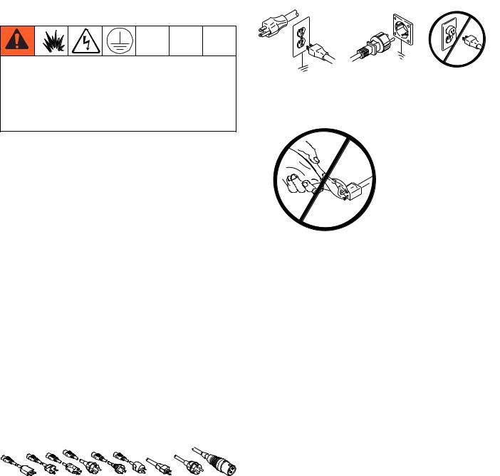
Warnings
Warnings
The following warnings are for the setup, use, grounding, maintenance, and repair of this equipment. The exclamation point symbol alerts you to a general warning and the hazard symbols refer to procedure-specific risks. When these symbols appear in the body of this manual or warning labels, refer back to these Warnings. Product-specific hazard symbols and warnings not covered in this section may appear throughout the body of this manual where applicable.
 WARNING
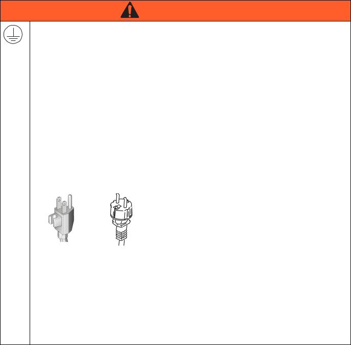
GROUNDING
This product must be grounded. In the event of an electrical short circuit, grounding reduces the risk of electric shock by providing an escape wire for the electric current. This product is equipped with a cord having a grounding wire with an appropriate grounding plug. The plug must be plugged into an outlet that is properly installed and grounded in accordance with all local codes and ordinances.
•Improper installation of the grounding plug is able to result in a risk of electric shock.
•When repair or replacement of the cord or plug is required, do not connect the grounding wire to either flat blade terminal.
•The wire with insulation having an outer surface that is green with or without yellow stripes is the grounding wire.
•Check with a qualified electrician or serviceman when the grounding instructions are not completely understood, or when in doubt as to whether the product is properly grounded.
•Do not modify the plug provided; if it does not fit the outlet, have the proper outlet installed by a qualified electrician.
•This product is for use on a nominal 120V or 230V circuit and has a grounding plug similar to the plugs illustrated in the figure below.
120V US |
230V |
•Only connect the product to an outlet having the same configuration as the plug.
•Do not use an adapter with this product. Extension Cords:
•Use only a 3-wire extension cord that has a grounding plug and a grounding receptacle that accepts the plug on the product.
•Make sure your extension cord is not damaged. If an extension cord is necessary, use 12 AWG
•(2.5 mm2) minimum to carry the current that the product draws.
•An undersized cord results in a drop in line voltage and loss of power and overheating.
4 |
332882A |
Warnings
 WARNING
FIRE AND EXPLOSION HAZARD
Flammable fumes, such as solvent and paint fumes, in work area can ignite or explode. To help prevent fire and explosion:
•Do not spray flammable or combustible materials near an open flame or sources of ignition such as cigarettes, motors, and electrical equipment.
•Paint or solvent flowing through the equipment is able to result in static electricity. Static electricity creates a risk of fire or explosion in the presence of paint or solvent fumes. All parts of the spray system, including the pump, hose assembly, spray gun, and objects in and around the spray area shall be properly grounded to protect against static discharge and sparks. Use Graco conductive or grounded high-pressure airless paint sprayer hoses.
•Verify that all containers and collection systems are grounded to prevent static discharge. Do not use pail liners unless they are antistatic or conductive.
•Connect to a grounded outlet and use grounded extensions cords. Do not use a 3-to-2 adapter.
•Do not use a paint or a solvent containing halogenated hydrocarbons.
•Keep spray area well-ventilated. Keep a good supply of fresh air moving through the area. Keep pump assembly in a well ventilated area. Do not spray pump assembly.
•Do not smoke in the spray area.
•Do not operate light switches, engines, or similar spark producing products in the spray area.
•Keep area clean and free of paint or solvent containers, rags, and other flammable materials.
•Know the contents of the paints and solvents being sprayed. Read all Material Safety Data Sheets (MSDS) and container labels provided with the paints and solvents. Follow the paint and solvents manufacturer’s safety instructions.
•Fire extinguisher equipment shall be present and working.
•Sprayer generates sparks. When flammable liquid is used in or near the sprayer or for flushing or cleaning, keep sprayer at least 20 feet (6 m) away from explosive vapors.
ELECTRIC SHOCK HAZARD
This equipment must be grounded. Improper grounding, setup, or usage of the system can cause electric shock.
•Turn off and disconnect power cord before servicing equipment.
•Use only grounded electrical outlets.
•Use only 3-wire extension cords.
•Ensure ground prongs are intact on power and extension cords.
•Do not expose to rain. Store indoors.
332882A |
5 |
Warnings
WARNING
SKIN INJECTION HAZARD
High-pressure spray is able to inject toxins into the body and cause serious bodily injury. In the event that injection occurs, get immediate surgical treatment.
• Do not aim the gun at, or spray any person or animal.
•Keep hands and other body parts away from the discharge. For example, do not try to stop leaks with any part of the body.
•Always use the nozzle tip guard. Do not spray without nozzle tip guard in place.
•Use Airlessco nozzle tips.
•Use caution when cleaning and changing nozzle tips. In the case where the nozzle tip clogs while spraying, follow the Pressure Relief Procedure, page 10 for turning off the unit and relieving the pressure before removing the nozzle tip to clean.
•Do not leave the unit energized or under pressure while unattended. When the unit is not in use, turn off the unit and follow the Pressure Relief Procedure, page 10 for turning off the unit.
•Check hoses and parts for signs of damage. Replace any damaged hoses or parts.
•This system is capable of producing 3000 psi. Use Airlessco replacement parts or accessories that are rated a minimum of 3000 psi.
•Always engage the trigger lock when not spraying. Verify the trigger lock is functioning properly.
•Verify that all connections are secure before operating the unit.
•Know how to stop the unit and bleed pressure quickly. Be thoroughly familiar with the controls.
EQUIPMENT MISUSE HAZARD
Misuse can cause death or serious injury.
•Always wear appropriate gloves, eye protection, and a respirator or mask when painting.
•Do not operate or spray near children. Keep children away from equipment at all times.
•Do not overreach or stand on an unstable support. Keep effective footing and balance at all times.
•Stay alert and watch what you are doing.
•Do not leave the unit energized or under pressure while unattended. When the unit is not in use, turn off the unit and follow the Pressure Relief Procedure, page 10 for turning off the unit.
•Do not operate the unit when fatigued or under the influence of drugs or alcohol.
•Do not kink or over-bend the hose.
•Do not expose the hose to temperatures or to pressures in excess of those specified by Graco.
•Do not use the hose as a strength member to pull or lift the equipment.
•Do not spray with a hose shorter than 25 feet.
•Do not alter or modify equipment. Alterations or modifications may void agency approvals and create safety hazards.
•Make sure all equipment is rated and approved for the environment in which you are using it.
PRESSURIZED ALUMINUM PARTS HAZARD
Use of fluids that are incompatible with aluminum in pressurized equipment can cause serious chemical reaction and equipment rupture. Failure to follow this warning can result in death, serious injury, or property damage.
•Do not use 1,1,1-trichloroethane, methylene chloride, other halogenated hydrocarbon solvents or fluids containing such solvents.
•Many other fluids may contain chemicals that can react with aluminum. Contact your material supplier for compatibility.
6 |
332882A |
Warnings
WARNING
MOVING PARTS HAZARD
Moving parts can pinch, cut or amputate fingers and other body parts.
•Keep clear of moving parts.
•Do not operate equipment with protective guards or covers removed.
•Pressurized equipment can start without warning. Before checking, moving, or servicing equipment, follow the Pressure Relief Procedure, page 10 and disconnect all power sources.
TOXIC FLUID OR FUMES HAZARD
Toxic fluids or fumes can cause serious injury or death if splashed in the eyes or on skin, inhaled, or swallowed.
•Read MSDSs to know the specific hazards of the fluids you are using.
•Store hazardous fluid in approved containers, and dispose of it according to applicable guidelines.
PERSONAL PROTECTIVE EQUIPMENT
You must wear appropriate protective equipment when operating, servicing, or when in the operating area of the equipment to help protect you from serious injury, including eye injury, hearing loss, inhalation of toxic fumes, and burns. This equipment includes but is not limited to:
•Protective eyewear, and hearing protection.
•Respirators, protective clothing, and gloves as recommended by the fluid and solvent manufacturer.
CALIFORNIA PROPOSITION 65
This product contains a chemical known to the State of California to cause cancer, birth defects or other reproductive harm. Wash hands after handling.
332882A |
7 |
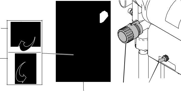
Component Identification
Component Identification
E
D
B |
A |
C |
ti22321a |
|
A |
Power switch |
Turns sprayer ON and OFF |
B |
Pressure Control Knob |
Adjusts pressure. Turn clockwise to increase pressure and |
|
|
counterclockwise to decrease pressure. |
C |
Prime Valve |
Primes pump. |
D |
Prime Valve Open Position |
Valve is in open position when handle is in the vertical position. |
E |
Prime Valve Closed Position |
Valve is in closed position when handle is in the horizontal posi- |
|
|
tion. |
|
|
|
8 |
332882A |
Operation
Grounding
The equipment must be grounded to reduce the risk of static sparking and electric shock. Electric or static sparking can cause fumes to ignite or explode.
Improper grounding can cause electric shock. Grounding provides an escape wire for the electric current.
Air and fluid hoses: use only electrically conductive hoses with a maximum of 500 ft. (150 m) combined hose length to ensure grounding continuity. Check electrical resistance of hoses. If total resistance to ground exceeds 29 megohms, replace hose immediately.
Spray gun: ground through connection to a properly grounded fluid hose and pump.
Fluid supply container: follow local code.
Object being sprayed: follow local code.
Solvent pails used when flushing: follow local code. Use only conductive metal pails, placed on a grounded surface. Do not place the pail on a nonconductive surface, such as paper or cardboard, which interrupts grounding continuity.
To maintain grounding continuity when flushing or relieving pressure: hold metal part of the spray gun/dispense valve firmly to the side of a grounded metal pail, then trigger the gun/valve.
The sprayer cord includes a grounding wire with an appropriate grounding contact.
The plug must be plugged into an outlet that is properly installed and grounded in accordance with all local codes and ordinances.
Operation
TI C
Do not modify the plug provided; if it does not fit the outlet, have the proper outlet installed by a qualified electrician.
Extension Cords: Use an extension cord with an undamaged ground contact. If an extension cord is nec-
essary, use a 3-wire, 12 AWG (2.5 mm2) minimum.
NOTE: Smaller gauge or longer extension cords may reduce sprayer performance.
332882A |
9 |
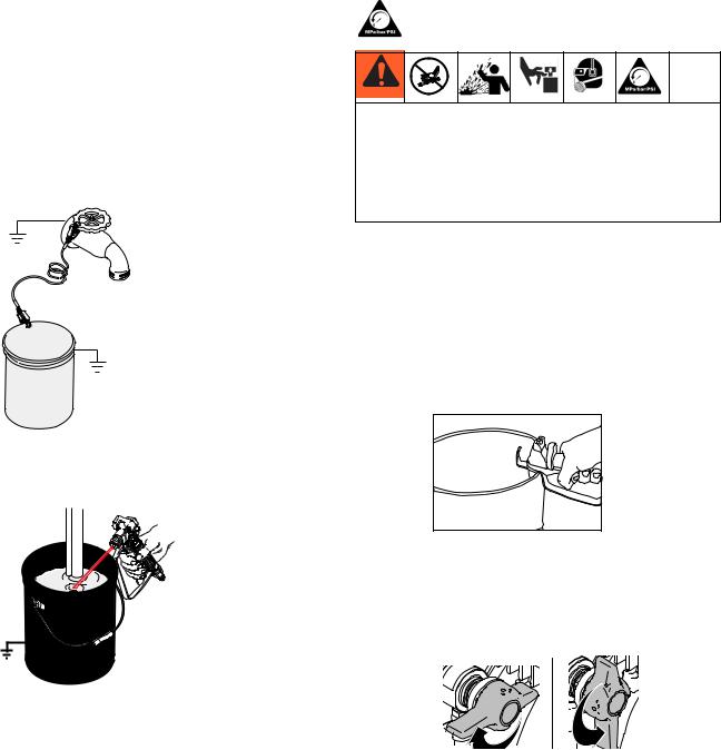
Operation
Pails
Solvent and oil/based fluids: follow local code. Use only conductive metal pails, placed on a grounded surface such as concrete.
Do not place pail on a nonconductive surface such as paper or cardboard which interrupts grounding continuity.
Grounding a metal pail: connect a ground wire to the pail by clamping one end to pail and other end to a true earth ground such as a water pipe.
ti5851a
To maintain grounding continuity when flushing or relieving pressure: hold metal part of spray gun firmly to side of a grounded metal pail. Then trigger gun.
ti5310b
Pressure Relief Procedure
Follow the Pressure Relief Procedure whenever you see this symbol.
This equipment stays pressurized until pressure is manually relieved. To help prevent serious injury from pressurized fluid, such as skin injection, splashing fluid and moving parts, follow the Pressure Relief Procedure when you stop spraying and before cleaning, checking, or servicing the equipment.
1.Engage the gun trigger lock. Refer to the separate instruction manual provided with gun for safety features and how to engage the trigger lock.
2.Turn the unit off.
3.Disengage the gun trigger lock and trigger the gun to relieve residual fluid pressure.
Hold metal part of the gun in contact with grounded metal pail. Use minimum pressure.
ti15989a
4.Re-engage gun trigger lock and turn Prime Valve to the open (priming) position.
Open Closed (Priming)
(Pressure)
ti17403a
NOTE: The valve handle can move both clockwise and counter clockwise and can face different directions.
NOTE: If you suspect the spray tip or hose is clogged or that pressure has not been fully relieved after following the steps above, VERY SLOWLY loosen tip guard retaining nut or hose end coupling to relieve pressure gradually, then loosen completely. Clear hose or tip obstruction.
10 |
332882A |
Loading...